02/28/05© 2005 university of wisconsin last time scattering theory integrating tranfer equations
TRANSCRIPT

02/28/05 © 2005 University of Wisconsin
Last Time
• Scattering theory
• Integrating tranfer equations
02/28/05 © 2005 University of Wisconsin
Today
• Sub-surface scattering
• Sky models

02/28/05 © 2005 University of Wisconsin
Subsurface Scattering
• Kubelka-Munk is a gross approximation to real scattering
• Subsurface scattering is very important to capturing the appearance of organic materials

02/28/05 © 2005 University of Wisconsin
BSSRDF
• Bidirectional surface scattering reflectance distribution function, S
• Relates the outgoing radiance at one point to the incident flux at another
• BRDF makes the assumption that xi = xo
• To get the total radiance leaving a point, integrate over the surface and the incoming directions
• S depends on the sub-surface scattering of the material
iiooiiooo xdxxSxdL ,,;,,

02/28/05 © 2005 University of Wisconsin
Practical Model
• Wann Jensen, Marschner, Levoy and Hanrahan, 2001
• Handles non-isotropic media
• Does not require extensive Monte-Carlo raytracing– Just a modified version of distribution ray-tracing
• Approximation based on:– Multiple bounce scattering – diffuse component
– Single bounce scattering – directional component
ooiiooiidooii xxSxxSxxS ,;,,;,,;, )1(

02/28/05 © 2005 University of Wisconsin
Single Scattering Term
• Assume one scattering event on the path from incoming to outgoing ray
• To get outgoing radiance, integrate along refracted ray
i oxi xo
s
A iiiiiiooii
iiiis
oiosooo
xdAdnxLxxS
dsdxLeFpxxL tc
2
)1(
02
)1(
,,;,
,,,

02/28/05 © 2005 University of Wisconsin
Single Scattering Term
• S(1) is defined by this formula
surfaceflat afor
factorgeometry a is where
ion terms transmissFresnel two,,
,,;,
,,,
tc
2
)1(
02
)1(
i
o
itot
itot
A iiiiiiooii
iiiis
oiosooo
n
nG
GxGx
FFF
xdAdnxLxxS
dsdxLeFpxxL tc

02/28/05 © 2005 University of Wisconsin
Multiple Scattering
• Observation: multiple scattering tends to look diffuse– Each scattering event tends to blur the distribution of radiance, until
it looks uniform
• For flat, semi-infinite surfaces, the effect of multiple scattering can be approximated with two virtual light sources– One inside the medium
– One “negative” light outside the medium
– The diffusion approximation

02/28/05 © 2005 University of Wisconsin
Diffuse Scattering Term (the flavor)
• This equation uses the Fresnel, coefficients to scale the incoming radiance, coefficients for transmission and adsorption, and variables for the location of the virtual light sources
otoiditooiid
vt
d
vtrvrt
d
rtrd
FxxRFxxS
d
edz
d
edrR
vtrrtr
,,
1,;,
114 33

02/28/05 © 2005 University of Wisconsin
Fitting Parameters
• There are 4 material dependent parameters: ’s, a, , – Each parameter, except , depends on
wavelength
• Measure by taking a high dynamic range image of a sample piece illuminated by a focused light– High dynamic range imagery will be
covered later
ooiiooiidooii xxSxxSxxS ,;,,;,,;, )1(

02/28/05 © 2005 University of Wisconsin
Rendering with the BSSRDF
• Rendering has to take into account:– Efficient integration of the BSSRDF
including importance sampling
– Single scattering for arbitrary geometry
– Diffuse scattering for arbitrary geometry
– Texture on the surface
• Use a distribution ray-tracer
• Each time you hit a surface point, xo, have to sample incoming points, xi to estimate integral
02/28/05 © 2005 University of Wisconsin
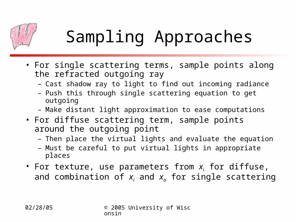
Sampling Approaches
• For single scattering terms, sample points along the refracted outgoing ray– Cast shadow ray to light to find out incoming radiance– Push this through single scattering equation to get outgoing– Make distant light approximation to ease computations
• For diffuse scattering term, sample points around the outgoing point– Then place the virtual lights and evaluate the equation– Must be careful to put virtual lights in appropriate places
• For texture, use parameters from xi for diffuse, and combination of xi and xo for single scattering
02/28/05 © 2005 University of Wisconsin
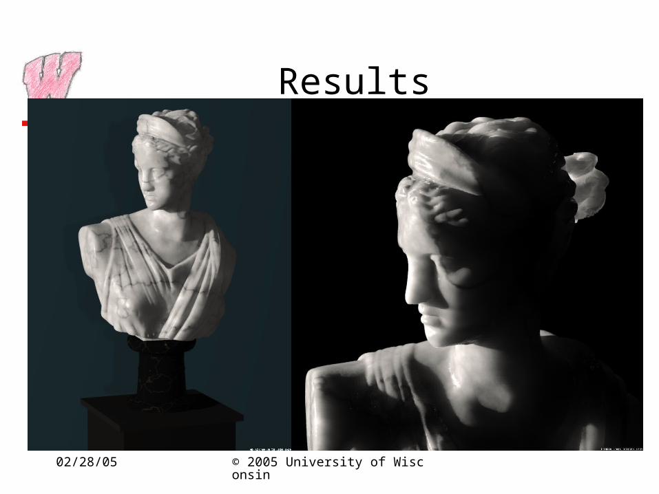
Results
02/28/05 © 2005 University of Wisconsin
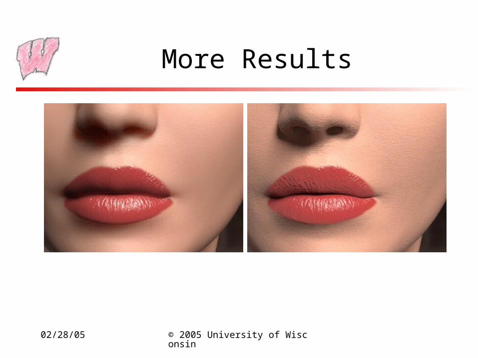
More Results

02/28/05 © 2005 University of Wisconsin
Can’t Escape the Bunny
02/28/05 © 2005 University of Wisconsin
Sky Illumination
• The sky is obviously an important source of illumination
• The atmosphere is an important participating medium over large distances (hundreds of meters)– People use atmospheric effects to judge distances (stereo and
disparity effects are useless at large distances)
• Three models:– CIE model
– Perez model
– Preetham, Shirley and Smits model

02/28/05 © 2005 University of Wisconsin
Atmospheric Phenomena
• Due to solar illumination and scattering in the atmosphere
• Air molecules are modeled by Rayleigh scattering– Optical extinction coefficient varies with -4
– What phenomena does this explain?
• Scattering due to larger particles is modeled with Mie scattering– Scattering depends less on wavelength, so what color is haze?
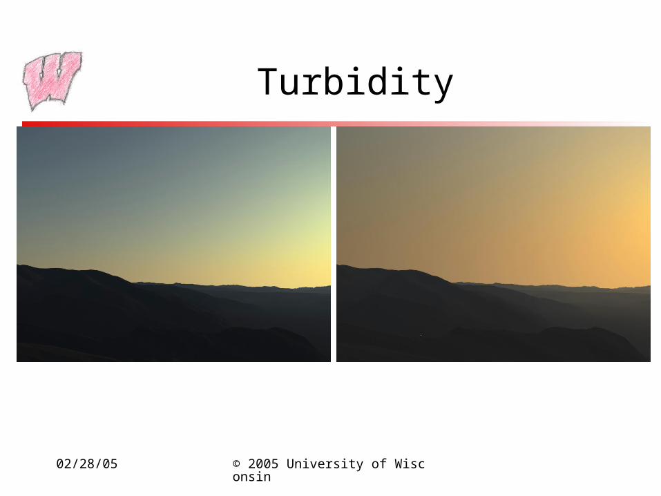
• Turbidity is a useful measurement: T=(tm+th)/tm
– tm is vertical optical thickness of molecular atmosphere
– th is vertical optical thickness of haze atmosphere
02/28/05 © 2005 University of Wisconsin
Simulation Models
• These attempt to simulate the scattering in the atmosphere to produce images– Very expensive for practical use
– But work with any atmospheric conditions
02/28/05 © 2005 University of Wisconsin
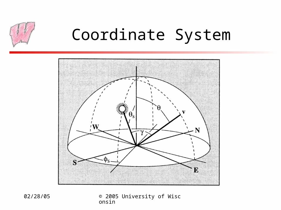
Coordinate System
02/28/05 © 2005 University of Wisconsin
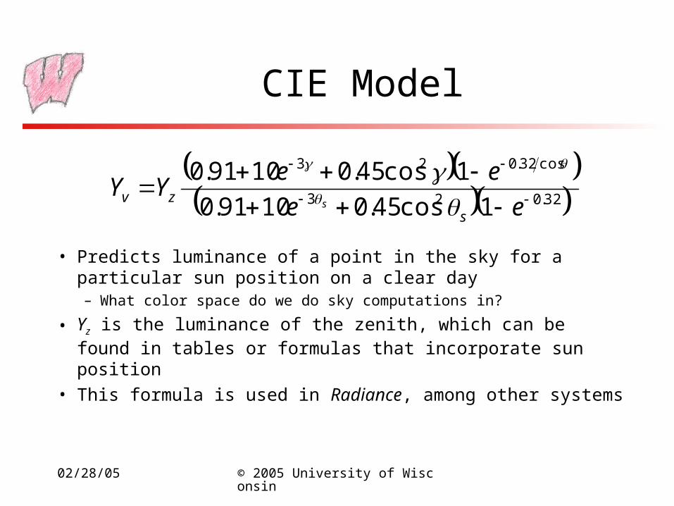
CIE Model
• Predicts luminance of a point in the sky for a particular sun position on a clear day– What color space do we do sky computations in?
• Yz is the luminance of the zenith, which can be found in tables or formulas that incorporate sun position
• This formula is used in Radiance, among other systems
32.023
cos32.023
1cos45.01091.0
1cos45.01091.0
ee
eeYY
szv s
02/28/05 © 2005 University of Wisconsin
CIE Cloud Model
• For completely overcast skies (thick clouds)
3
cos21 zv YY

02/28/05 © 2005 University of Wisconsin
Perez Model
• Five parameters:– A: darkening or brightening of the horizon
– B: luminance gradient near the horizon
– C: relative intensity of the circum-solar region
– D: width of the circum-solar region
– E: relative backscattered light
szv
DB
FFYY
ECeAeF
,0,
cos11, 2cos
02/28/05 © 2005 University of Wisconsin
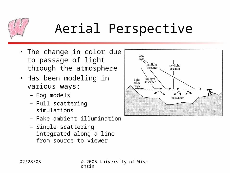
Aerial Perspective
• The change in color due to passage of light through the atmosphere
• Has been modeling in various ways:– Fog models
– Full scattering simulations
– Fake ambient illumination
– Single scattering integrated along a line from source to viewer

02/28/05 © 2005 University of Wisconsin
Preetham, Shirley and Smits
• Practical model (or so they claim)
• Model sun with NASA data and attenuation along path to viewer
• Model skylight with Perez model– Run lots of simulation of particle scattering
– Fit parameters for Perez model
– Also fit chromaticity values
• Model aerial perspective with simplifications to scattering integrals

02/28/05 © 2005 University of Wisconsin
Results
02/28/05 © 2005 University of Wisconsin
Turbidity

02/28/05 © 2005 University of Wisconsin
Ward’s Model vs Preetham
02/28/05 © 2005 University of Wisconsin
Next Time
• High Dynamic Range