024, 026 contentslancfuresz.gportal.hu/portal/lancfuresz/upload/717021...carburetor parts kit...
TRANSCRIPT
1. Safety Precautions 1
2. Introduction 2
3. Specifications 3
3.1 Engine 33.2 Fuel System 33.3 Ignition System 43.4 Cutting Attachment 43.5 Special Accessories 43.5.1 For User 43.5.2 For Service 53.6 Tightening Torques 5
4. Clutch, Chain Drive,Chain Brake andChain Tensioner 7
4.1 Clutch Drum andChain Sprocket 7
4.2 Clutch 84.3 Chain Brake 94.3.1 Checking Function 94.3.2 Disassembling 94.3.3 Assembling 114.3.4 Anchor Pin for
Brake Spring 134.3.5 Pin for Hand Guard 134.4 Front Chain
Tensioner (024) 144.5 Side Chain Tensioner 14
5. Engine 15
5.1 Muffler/SparkArresting Screen 15
5.2 Catalytic Converter 165.2.1 Construction and
Function 165.3 Leakage Test 175.3.1 Preparations 175.3.2 Pressure Test 185.3.3 Vacuum Test 185.4 Oil Seals 195.5 Exposing the Cylinder 215.6 Cylinder and Piston 215.6.1 Removing 215.6.2 Installing 225.7 Piston Rings 255.8 Crankcase 255.8.1 Removing the
Crankshaft 255.8.2 Installing the
Crankshaft 285.9 Decompression Valve 33
6. Ignition System 33
6.1 Spark Plug Boot/Ignition Lead 33
6.2 Ignition Module 346.2.1 Ignition Timing 356.2.2 Removing and Installing 356.3 Short Circuit Wire/
Ground Wire 366.4 Wiring Harness 376.5 Contact Spring 386.6 Flywheel 38
7. Rewind Starter 39
7.1 General 397.2 Rewind Spring 397.2.1 Replacing 397.2.2 Tensioning 407.3 Starter Rope/Starter
Grip (ElastoStart) 41
8. AV Handle System 42
9. Master Control/Handle System 43
9.1 Switch Shaft 439.2 Interlock Lever/
Throttle Trigger 43
10. Electric HandleHeating System 45
10.1 Troubleshooting 4510.1.1 Troubleshooting
Chart 4610.1.2 Test Connections and
Test Values 4710.2 Heater Switch 4810.3 Heating Element in
Rear Handle 4810.4 Heating Element in
Front Handle 4910.5 Generator 50
11. Chain Lubrication 52
11.1 Pickup Body/Suction Hose 52
11.2 Valve 5311.3 Oil Pump 5311.3.1 Servicing 55
12. Fuel System 55
12.1 Air Filter/Choke Shutter 5512.2 Carburetor Preheating 5612.3 Carburetor Heater 5612.3.1 Construction and
Function 5612.3.2 Testing 5712.3.3 Troubleshooting
Chart 5912.4 Printed Circuit Board 60
12.5 Carburetor 6012.5.1 Leakage Testing 6012.5.2 Removing and
Installing 6112.5.3 Adjusting 6312.6 Tank Vent 6412.7 Fuel Hose 6512.8 Tank Housing 65
13. Special ServicingTools and Aids 68
13.1 Special ServicingTools 68
13.2 Servicing Aids 70
1. SAFETYPRECAUTIONS
If the engine is started up in thecourse of repairs or maintenancework, observe all local and country-specific safety regulations as wellas the safety precautions and war-nings in the owner’s manual.
Gasoline is an extremely flamm-able fuel and can be explosive incertain conditions.
Improper handling may result inburns or other serious injuries.
Warning! Do not smoke or bringany fire or flame near the fuel. Allwork with fuel must be performedoutdoors only. Spilled fuel must bewiped up immediately.
Wash hands thoroughly afterevery contact with waste oil.
Do not pour waste oil down thedrain or allow it to soak into theground.
Collect waste oil and take it to anofficial disposal site for environ-ment-friendly disposal.
© 1999 Andreas Stihl AG & Co., Waiblingen
024, 026CONTENTS
024, 026 1
This service manual containsdetailed descriptions of all therepair and servicing proceduresspecific to this power tool series.There are separate handbooksfor servicing procedures forstandardized parts and assem-blies that are installed in severalSTIHL power tool models.Reference is made to thesehandbooks in the appropriatechapters of this manual.
As the design concept of model024 and 026 chainsaws is almostidentical, the descriptions andservicing procedures generallyapply to both. Differences aredescribed in detail.
Servicing procedures on thecarburetor are described in the"Carburetors" handbook.
You should make use of theillustrated parts lists while carryingout repair work. They show theinstalled positions of the individualcomponents and assemblies.
Refer to the latest edition of therelevant parts list to check the partnumbers of any replacement partsneeded.Parts lists on microfiche and CD-ROM are always more up to datethan printed lists.
A fault on the machine may haveseveral causes. To help locate thefault, consult the troubleshootingcharts for all assemblies in the"Standard Repairs, Troubleshoot-ing" handbook.
Refer to the "Technical Informa-tion" bulletins for engineeringchanges which have been intro-duced since publication of thisservice manual. Technical informa-tion bulletins also supplement theparts list until a revised edition isissued.
The special servicing toolsmentioned in the descriptions arelisted in the last chapter of this ma-nual.Use the part numbers to identifythe tools in the "STIHL SpecialTools" manual.The manual lists all specialservicing tools currently availablefrom STIHL.
Symbols are included in the textand pictures for greater clarity.The meanings are as follows:
In the descriptions:
• = Action to be taken asshown in the illustration(above the text)
- = Action to be taken thatis not shown in theillustration(above the text)
In the illustrations:
= Pointer
= Direction of movement
Service manuals and all technicalinformation bulletins describingengineering changes are intendedexclusively for the use of STIHLservicing dealers. They must notbe passed to third parties.
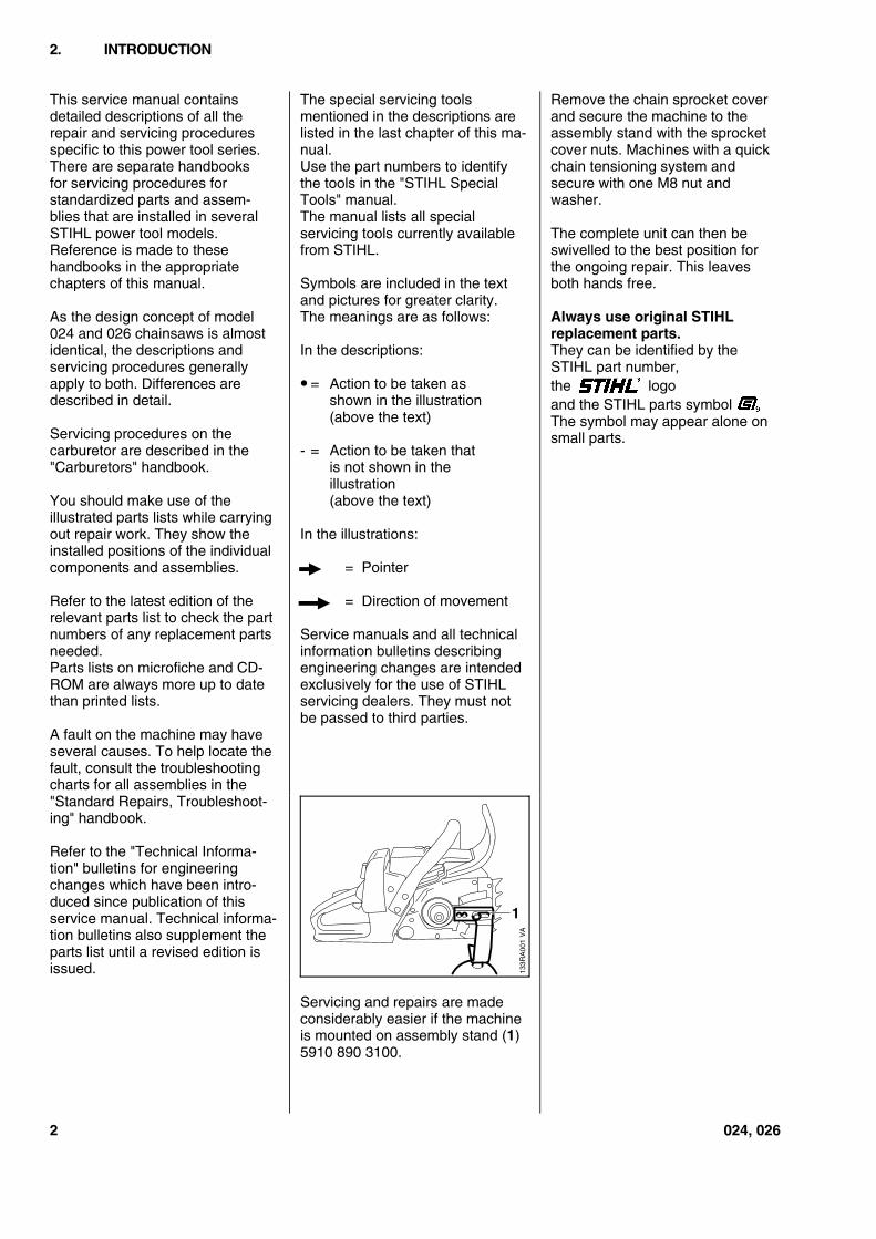
Servicing and repairs are madeconsiderably easier if the machineis mounted on assembly stand (1)5910 890 3100.
Remove the chain sprocket coverand secure the machine to theassembly stand with the sprocketcover nuts. Machines with a quickchain tensioning system andsecure with one M8 nut andwasher.
The complete unit can then beswivelled to the best position forthe ongoing repair. This leavesboth hands free.
Always use original STIHLreplacement parts.They can be identified by theSTIHL part number,the logoand the STIHL parts symbol(The symbol may appear alone onsmall parts.
2. INTRODUCTION
VA
133R
A00
1
1
2 024, 026
3.1 Engine
STIHL single-cylinder two-stroke engine with special impregnated cylinder bore
024 024 S 026
Displacement: 42 cm3 (2.56 cu.in) 44.3 cm3 (2.70 cu.in) 48.7 cm3 (2.97 cu.in)Bore: 42 mm (1.65 in) 42 mm (1.65 in) 44 mm (1.73 in)Stroke: 30 mm (1.18 in) 32 mm (1.26 in) 32 mm (1.26 in)Engine power to ISO 7293: 2.1 kW (2.85 bhp) 2.3 kW (3.1 bhp) 2.6 kW (3.5 bhp)
at 7,000 rpm at 7,000 rpm at 7,000 rpmMax. permissible enginespeed with bar and chain: 13,000 rpm 13,000 rpm 14,000 rpmIdle speed: 2,500 rpmBearings: Crankshaft supported in heavy-duty deep-groove ball bearings,
needle cages on small and big endsPiston pin diameter: 10 mm (0.39 in)Rewind starter: Single pawl systemReserve pull on rope rotor: min. 1/2 turnStarter rope: 3.5 mm (0.14 in) dia.Clutch: Centrifugal clutch without liningsClutch engages at: 3,600 rpmCrankcase leakagetestat gauge pressure: 0.5 bar (7.25 psi)under vacuum: 0.5 bar (7.25 psi)
3.2 Fuel System
Carburetor: Diaphragm carburetorSettingHigh speed screw H: approx. 1 turn openLow speed screw L: approx. 1 turn open
(standard setting)Carburetor leakage testat gauge pressure: 0.8 bar (11.6 psi)Function of tank ventat gauge pressure: ≤ 0.3 bar (4.35 psi)under vacuum: * ≤ 0.05 bar (0.725 psi)Fuel tank capacity: 0.47 L (16 fl.oz)Octane number: min. 90 RONFuel mixture: Regular brand-name gasoline
and two-stroke engine oilMix ratio: 50:1 with STIHL 50:1 two-stroke engine oil
25:1 with other brand-name two-stroke, air-cooled engine oilsAir filter: Large area, bisectional flat filter,
additional prefilter in carburetor box cover
* Original tank vent
3. SPECIFICATIONS
024, 026 3
3.3 Ignition System Type: Electronic magneto ignition(breakerless) with integraltrigger unit
Air gap: 0.2-0.3 mm (0.008-0.012 in)Spark plug (suppressed): Bosch WSR 6F,
NGK BPMR 7 A orChampion RCJ 6Y
Electrode gap: 0.5 mm (0.020 in)
3.4 Cutting Attachment Guide bars: STIHL Rollomaticwith nose sprocket,corrosion-resistant finish andinduction hardened rails
Bar lengths: 32, 37 and 40 cm (13, 15, 18 in)Oilomatic chain: 0.325" (8.25 mm) Rapid chainChain sprocket: 7-tooth 0.325"Chain speed: 18.3 m/s (60 ft/s) at 9,500 rpmChain lubrication: Speed-controlled or adjustable
reciprocating pumpOil feed rateon non-adjustable pump: 6 cm3/min (0.2 fl.oz/min)
at 6,000 rpm9.5 cm3/min (0.3 fl.oz/min)at 10,000 rpm
on adjustable pump: 4.5-11.5 cm3/min(0.15-0.4 fl.oz/min)at 10,000 rpm
Oil tank capacity: 0.32 L (11 fl.oz)
3.5 Special Accessories
3.5.1 For User ElastoStart 0000 190 3401Air filter, "fleece" 024 1121 120 16250.325", 8-tooth chain sprocket 1121 640 2001 1)
1121 640 2005 2)Intake air preheating kit 024 1121 007 1030Intake air preheating kit 026 1121 007 1027
(up to serial number X 30 976 774)Intake air preheating kit 026 1121 007 1044
(from serial number X 30 976 775)0.325", 7-tooth rim sprocket kit 1121 007 1001 1)
1121 007 1037 2)0.325", 8-tooth rim sprocket kit 1121 007 1002 1)
1121 007 1038 2)3/8" Picco, 7-tooth rim sprocket kit 1121 007 1004 1)
1121 007 1039 2)3/8" Picco, 8-tooth rim sprocket kit 1121 007 1005 1)
1121 007 1040 2)3/8", 7-tooth rim sprocket kit 1121 007 1035 1)
1121 007 1041 2)Chain scabbard extension(from 45 cm/18 in) 0000 792 9131CAT mounting kit 1121 007 1042
1) 0242) 026
4 024, 026
3.5.2 For Service Carburetor parts kit 024, small 1118 007 1060 (Tillotson)Carburetor parts kit 024, large 1118 007 1065 (Tillotson)Carburetor parts kit 024/026, large 1121 007 1062 (Walbro)Carburetor parts kit 024/026, large 1118 007 1066 (Walbro WT 22)Gasket set 024/026 1121 007 1050
3.6 Tightening Torques
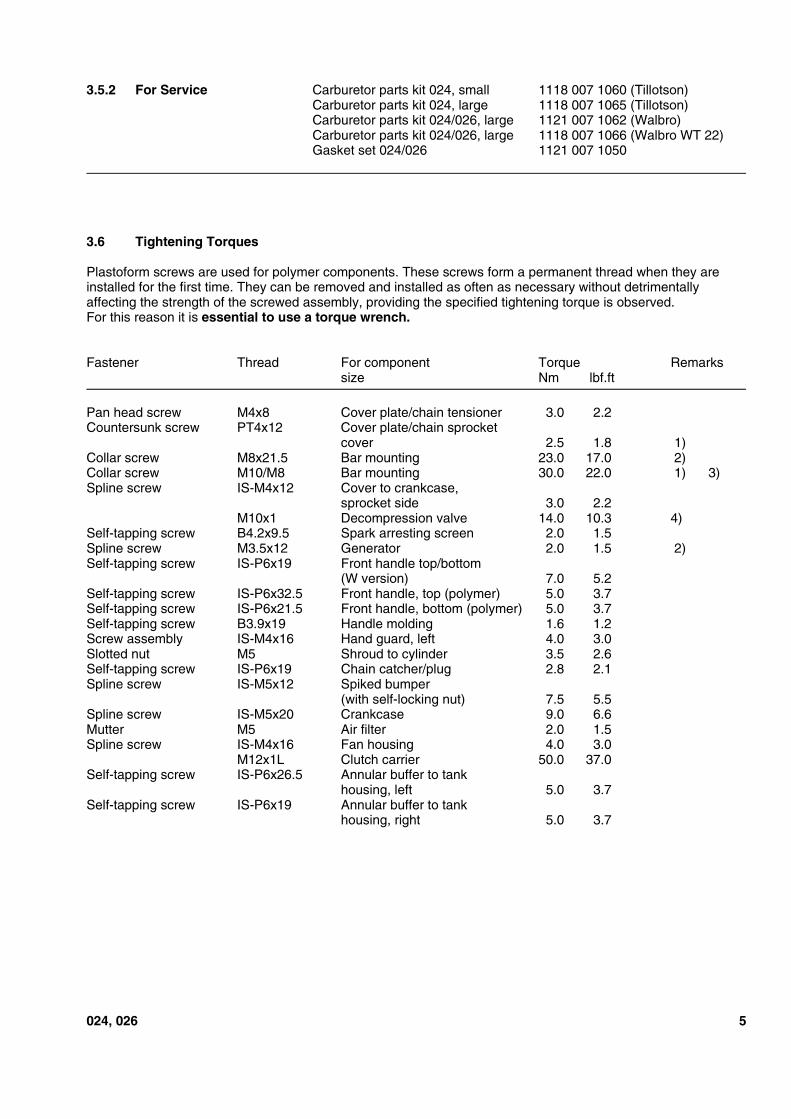
Plastoform screws are used for polymer components. These screws form a permanent thread when they areinstalled for the first time. They can be removed and installed as often as necessary without detrimentallyaffecting the strength of the screwed assembly, providing the specified tightening torque is observed.For this reason it is essential to use a torque wrench.
Fastener Thread For component Torque Remarkssize Nm lbf.ft
Pan head screw M4x8 Cover plate/chain tensioner 3.0 2.2Countersunk screw PT4x12 Cover plate/chain sprocket
cover 2.5 1.8 1)Collar screw M8x21.5 Bar mounting 23.0 17.0 2)Collar screw M10/M8 Bar mounting 30.0 22.0 1) 3)Spline screw IS-M4x12 Cover to crankcase,
sprocket side 3.0 2.2M10x1 Decompression valve 14.0 10.3 4)
Self-tapping screw B4.2x9.5 Spark arresting screen 2.0 1.5Spline screw M3.5x12 Generator 2.0 1.5 2)Self-tapping screw IS-P6x19 Front handle top/bottom
(W version) 7.0 5.2Self-tapping screw IS-P6x32.5 Front handle, top (polymer) 5.0 3.7Self-tapping screw IS-P6x21.5 Front handle, bottom (polymer) 5.0 3.7Self-tapping screw B3.9x19 Handle molding 1.6 1.2Screw assembly IS-M4x16 Hand guard, left 4.0 3.0Slotted nut M5 Shroud to cylinder 3.5 2.6Self-tapping screw IS-P6x19 Chain catcher/plug 2.8 2.1Spline screw IS-M5x12 Spiked bumper
(with self-locking nut) 7.5 5.5Spline screw IS-M5x20 Crankcase 9.0 6.6Mutter M5 Air filter 2.0 1.5Spline screw IS-M4x16 Fan housing 4.0 3.0
M12x1L Clutch carrier 50.0 37.0Self-tapping screw IS-P6x26.5 Annular buffer to tank
housing, left 5.0 3.7Self-tapping screw IS-P6x19 Annular buffer to tank
housing, right 5.0 3.7
024, 026 5
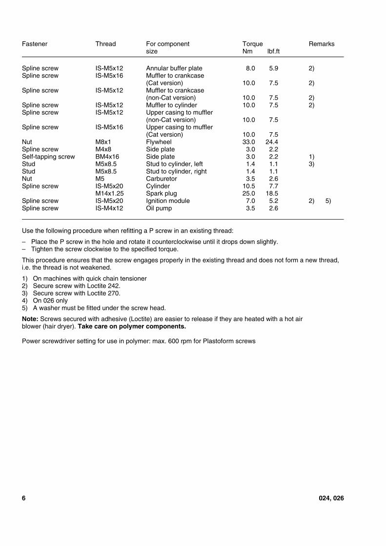
Fastener Thread For component Torque Remarkssize Nm lbf.ft
Spline screw IS-M5x12 Annular buffer plate 8.0 5.9 2)Spline screw IS-M5x16 Muffler to crankcase
(Cat version) 10.0 7.5 2)Spline screw IS-M5x12 Muffler to crankcase
(non-Cat version) 10.0 7.5 2)Spline screw IS-M5x12 Muffler to cylinder 10.0 7.5 2)Spline screw IS-M5x12 Upper casing to muffler
(non-Cat version) 10.0 7.5Spline screw IS-M5x16 Upper casing to muffler
(Cat version) 10.0 7.5Nut M8x1 Flywheel 33.0 24.4Spline screw M4x8 Side plate 3.0 2.2Self-tapping screw BM4x16 Side plate 3.0 2.2 1)Stud M5x8.5 Stud to cylinder, left 1.4 1.1 3)Stud M5x8.5 Stud to cylinder, right 1.4 1.1Nut M5 Carburetor 3.5 2.6Spline screw IS-M5x20 Cylinder 10.5 7.7
M14x1.25 Spark plug 25.0 18.5Spline screw IS-M5x20 Ignition module 7.0 5.2 2) 5)Spline screw IS-M4x12 Oil pump 3.5 2.6
Use the following procedure when refitting a P screw in an existing thread:
– Place the P screw in the hole and rotate it counterclockwise until it drops down slightly.– Tighten the screw clockwise to the specified torque.
This procedure ensures that the screw engages properly in the existing thread and does not form a new thread,i.e. the thread is not weakened.
1) On machines with quick chain tensioner2) Secure screw with Loctite 242.3) Secure screw with Loctite 270.4) On 026 only5) A washer must be fitted under the screw head.
Note: Screws secured with adhesive (Loctite) are easier to release if they are heated with a hot airblower (hair dryer). Take care on polymer components.
Power screwdriver setting for use in polymer: max. 600 rpm for Plastoform screws
6 024, 026
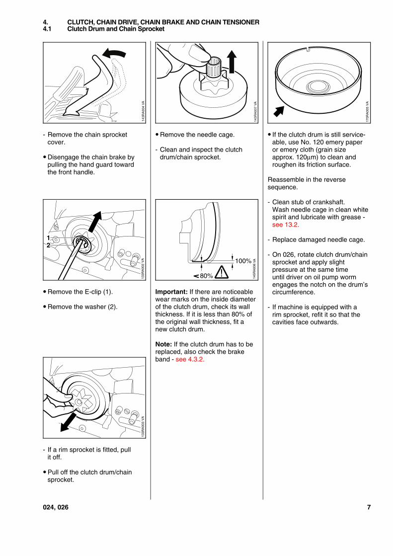
- Remove the chain sprocketcover.
• Disengage the chain brake bypulling the hand guard towardthe front handle.
• Remove the E-clip (1).
• Remove the washer (2).
- If a rim sprocket is fitted, pullit off.
• Pull off the clutch drum/chainsprocket.
• Remove the needle cage.
- Clean and inspect the clutchdrum/chain sprocket.
Important: If there are noticeablewear marks on the inside diameterof the clutch drum, check its wallthickness. If it is less than 80% ofthe original wall thickness, fit anew clutch drum.
Note: If the clutch drum has to bereplaced, also check the brakeband - see 4.3.2.
• If the clutch drum is still service-able, use No. 120 emery paperor emery cloth (grain sizeapprox. 120µm) to clean androughen its friction surface.
Reassemble in the reversesequence.
- Clean stub of crankshaft.Wash needle cage in clean whitespirit and lubricate with grease -see 13.2.
- Replace damaged needle cage.
- On 026, rotate clutch drum/chainsprocket and apply slightpressure at the same timeuntil driver on oil pump wormengages the notch on the drum’scircumference.
- If machine is equipped with arim sprocket, refit it so that thecavities face outwards.
4. CLUTCH, CHAIN DRIVE, CHAIN BRAKE AND CHAIN TENSIONER4.1 Clutch Drum and Chain Sprocket
VA
143R
A00
7
VA
170R
A00
5
VA
133R
A00
2
12
80%
100%14
5RA
006
!
VA
VA
133R
A00
3
024, 026 7
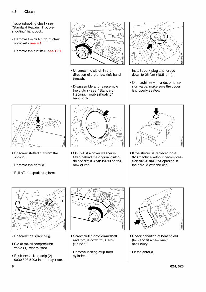
Troubleshooting chart - see"Standard Repairs, Trouble-shooting" handbook.
- Remove the clutch drum/chainsprocket - see 4.1.
- Remove the air filter - see 12.1.
• Unscrew slotted nut from theshroud.
- Remove the shroud.
- Pull off the spark plug boot.
- Unscrew the spark plug.
• Close the decompressionvalve (1), where fitted.
• Push the locking strip (2)0000 893 5903 into the cylinder.
• Unscrew the clutch in thedirection of the arrow (left-handthread).
- Disassemble and reassemblethe clutch - see "StandardRepairs, Troubleshooting"handbook.
• On 024, if a cover washer isfitted behind the original clutch,do not refit it when installing thenew clutch.
• Screw clutch onto crankshaftand torque down to 50 Nm(37 lbf.ft).
- Remove locking strip fromcylinder.
- Install spark plug and torquedown to 25 Nm (18.5 lbf.ft).
• On machines with a decompres-sion valve, make sure the coveris properly seated.
• If the shroud is replaced on a026 machine without decompres-sion valve, seal the opening inthe shroud with the cap.
• Check condition of heat shield(foil) and fit a new one ifnecessary.
- Fit the shroud.
4.2 Clutch
VA
133R
A00
7
VA
133R
A01
0
VA
133R
A00
4
VA
133R
A00
8
VA
133R
A03
5
VA
133R
A00
6
2
1
VA
133R
A00
9
VA
133R
A00
5
8 024, 026
The chain brake is one of the mostimportant safety devices on thechain saw. Its efficiency is measu-red in terms of braking time, i.e.the time that elapses betweenactivating the brake and the sawchain coming to a standstill. Theshorter the braking time, the betterthe efficiency and protectionoffered.
Contamination (with chain oil,chips, fine particles of abrasion,etc.) and smoothing of the frictionsurfaces of the brake band andclutch drum impair the coefficientof friction. This, in turn, reducesthe frictional forces and thus pro-longs the braking time. A fatiguedor stretched brake spring has thesame negative effect.
- Start the engine.
- With the chain brake activated(locked), open throttle wide forbrief period (max. 3 seconds) -the chain must not rotate.
- With the chain brake released,open throttle wide and activatethe brake manually - the chainmust come to an abruptstop.
Note: The braking time is inorder if deceleration of thesaw chain is imperceptible tothe eye.
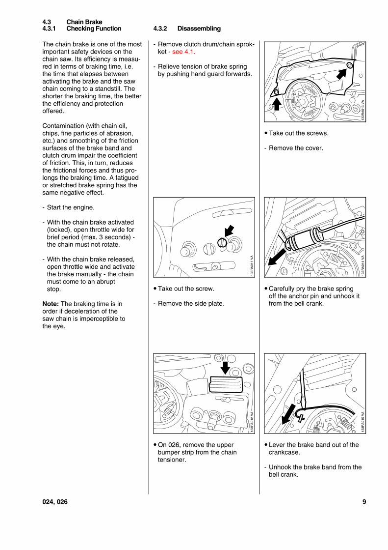
- Remove clutch drum/chain sprok-ket - see 4.1.
- Relieve tension of brake springby pushing hand guard forwards.
• Take out the screw.
- Remove the side plate.
• On 026, remove the upperbumper strip from the chaintensioner.
• Take out the screws.
- Remove the cover.
• Carefully pry the brake springoff the anchor pin and unhook itfrom the bell crank.
• Lever the brake band out of thecrankcase.
- Unhook the brake band from thebell crank.
4.3 Chain Brake4.3.1 Checking Function 4.3.2 Disassembling
VA
133R
A01
3V
A13
3RA
014
VA
133R
A01
1V
A13
3RA
012
133R
A01
5V
A
024, 026 9
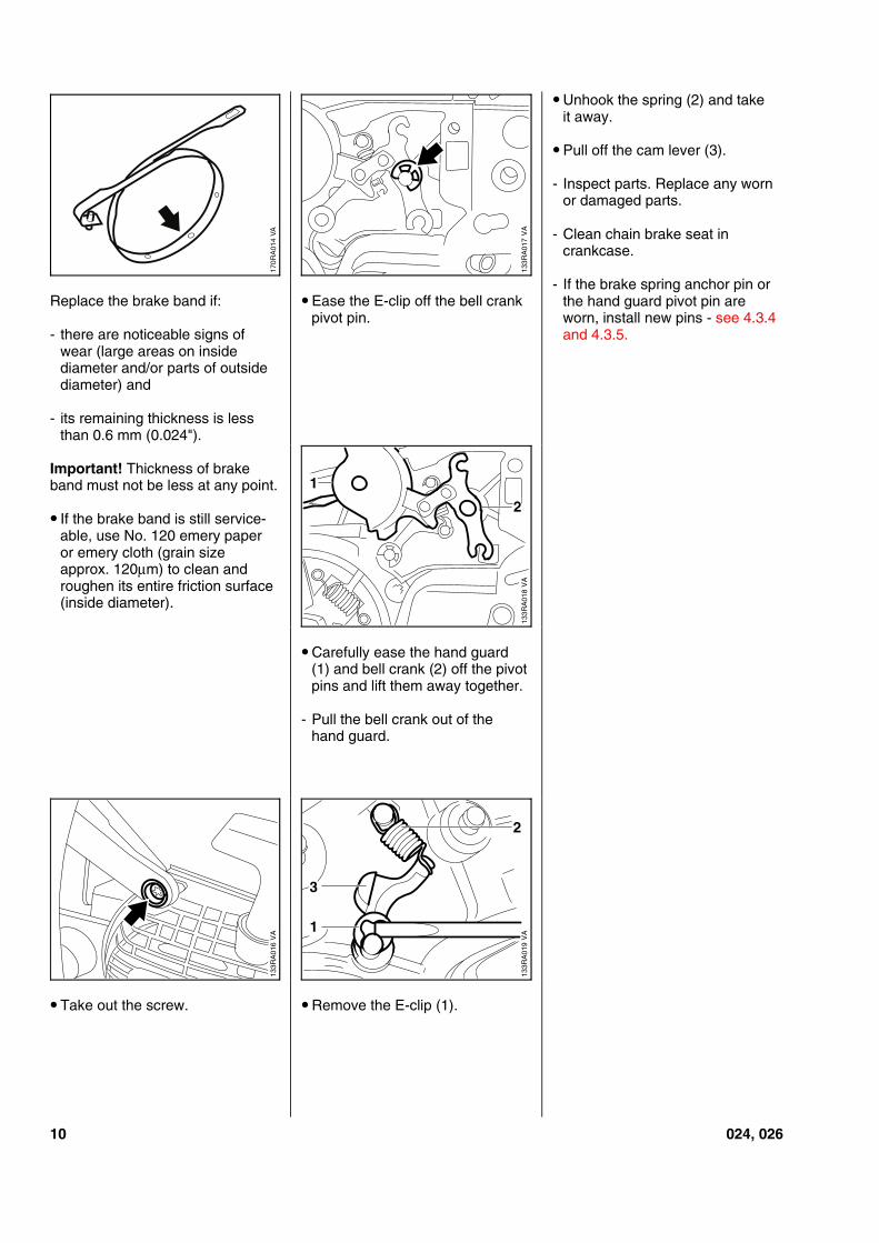
Replace the brake band if:
- there are noticeable signs ofwear (large areas on insidediameter and/or parts of outsidediameter) and
- its remaining thickness is lessthan 0.6 mm (0.024").
Important! Thickness of brakeband must not be less at any point.
• If the brake band is still service-able, use No. 120 emery paperor emery cloth (grain sizeapprox. 120µm) to clean androughen its entire friction surface(inside diameter).
• Take out the screw.
• Ease the E-clip off the bell crankpivot pin.
• Carefully ease the hand guard(1) and bell crank (2) off the pivotpins and lift them away together.
- Pull the bell crank out of thehand guard.
• Remove the E-clip (1).
• Unhook the spring (2) and takeit away.
• Pull off the cam lever (3).
- Inspect parts. Replace any wornor damaged parts.
- Clean chain brake seat incrankcase.
- If the brake spring anchor pin orthe hand guard pivot pin areworn, install new pins - see 4.3.4and 4.3.5.
VA
170R
A01
4
133R
A01
7V
A13
3RA
018
VA
1
2V
A13
3RA
019
3
1
2
VA
133R
A01
6
10 024, 026
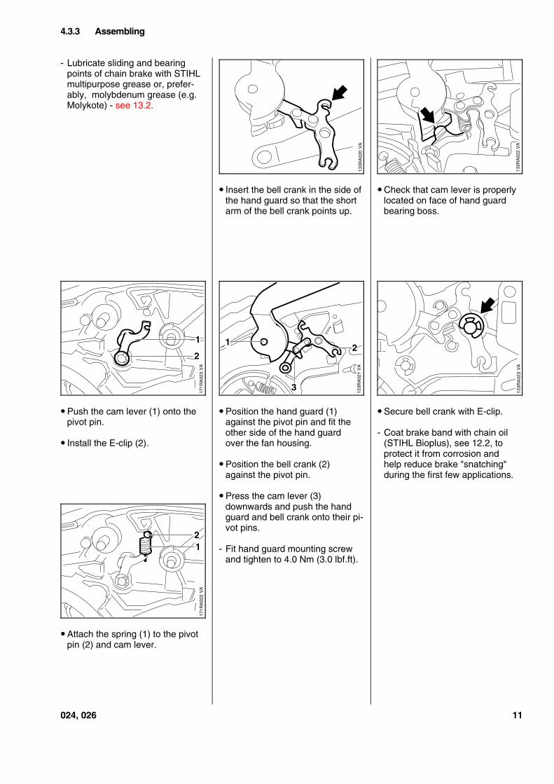
- Lubricate sliding and bearingpoints of chain brake with STIHLmultipurpose grease or, prefer-ably, molybdenum grease (e.g.Molykote) - see 13.2.
• Push the cam lever (1) onto thepivot pin.
• Install the E-clip (2).
• Attach the spring (1) to the pivotpin (2) and cam lever.
• Insert the bell crank in the side ofthe hand guard so that the shortarm of the bell crank points up.
• Position the hand guard (1)against the pivot pin and fit theother side of the hand guardover the fan housing.
• Position the bell crank (2)against the pivot pin.
• Press the cam lever (3)downwards and push the handguard and bell crank onto their pi-vot pins.
- Fit hand guard mounting screwand tighten to 4.0 Nm (3.0 lbf.ft).
• Check that cam lever is properlylocated on face of hand guardbearing boss.
• Secure bell crank with E-clip.
- Coat brake band with chain oil(STIHL Bioplus), see 12.2, toprotect it from corrosion andhelp reduce brake "snatching"during the first few applications.
4.3.3 Assembling
133R
A02
0V
A
133R
A02
2V
A
VA
171R
A02
3
2
1
VA
133R
A02
1
12
3
133R
A02
3V
A
VA
171R
A02
2
21
024, 026 11
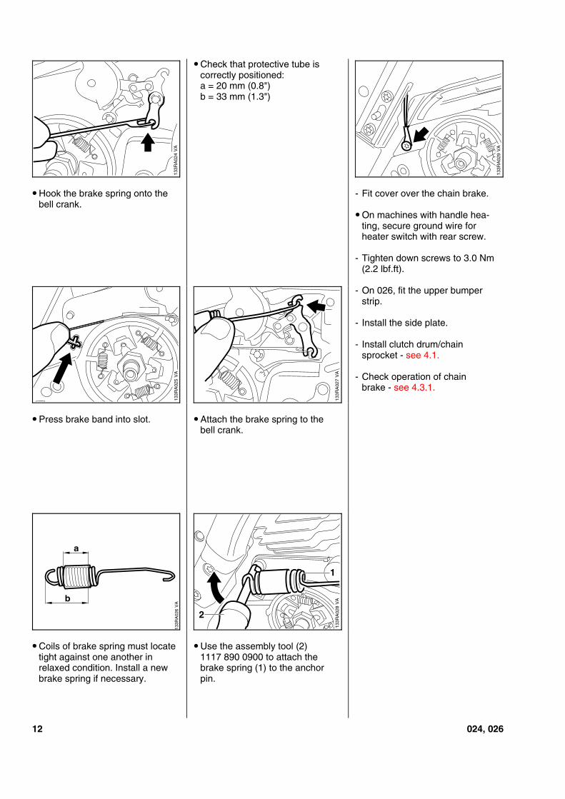
• Hook the brake spring onto thebell crank.
• Press brake band into slot.
• Coils of brake spring must locatetight against one another inrelaxed condition. Install a newbrake spring if necessary.
• Check that protective tube iscorrectly positioned:a = 20 mm (0.8")b = 33 mm (1.3")
• Attach the brake spring to thebell crank.
• Use the assembly tool (2)1117 890 0900 to attach thebrake spring (1) to the anchorpin.
- Fit cover over the chain brake.
• On machines with handle hea-ting, secure ground wire forheater switch with rear screw.
- Tighten down screws to 3.0 Nm(2.2 lbf.ft).
- On 026, fit the upper bumperstrip.
- Install the side plate.
- Install clutch drum/chainsprocket - see 4.1.
- Check operation of chainbrake - see 4.3.1.
133R
A02
4V
A
VA
133R
A02
9
133R
A02
5V
A
133R
A02
7V
A
VA
133R
A02
6
b
a
VA
133R
A02
8
2
1
12 024, 026
- Remove the cylinder - see 5.6.1.
- Remove the chain brake - see4.3.2.
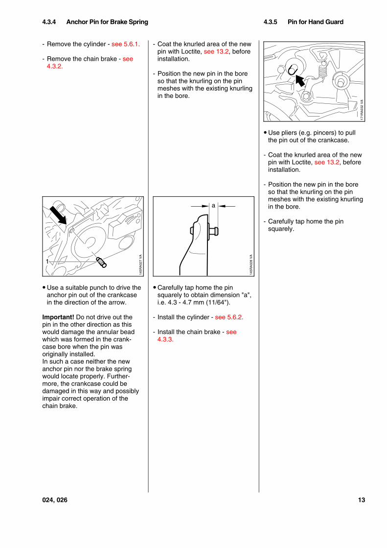
• Use a suitable punch to drive theanchor pin out of the crankcasein the direction of the arrow.
Important! Do not drive out thepin in the other direction as thiswould damage the annular beadwhich was formed in the crank-case bore when the pin wasoriginally installed.In such a case neither the newanchor pin nor the brake springwould locate properly. Further-more, the crankcase could bedamaged in this way and possiblyimpair correct operation of thechain brake.
- Coat the knurled area of the newpin with Loctite, see 13.2, beforeinstallation.
- Position the new pin in the boreso that the knurling on the pinmeshes with the existing knurlingin the bore.
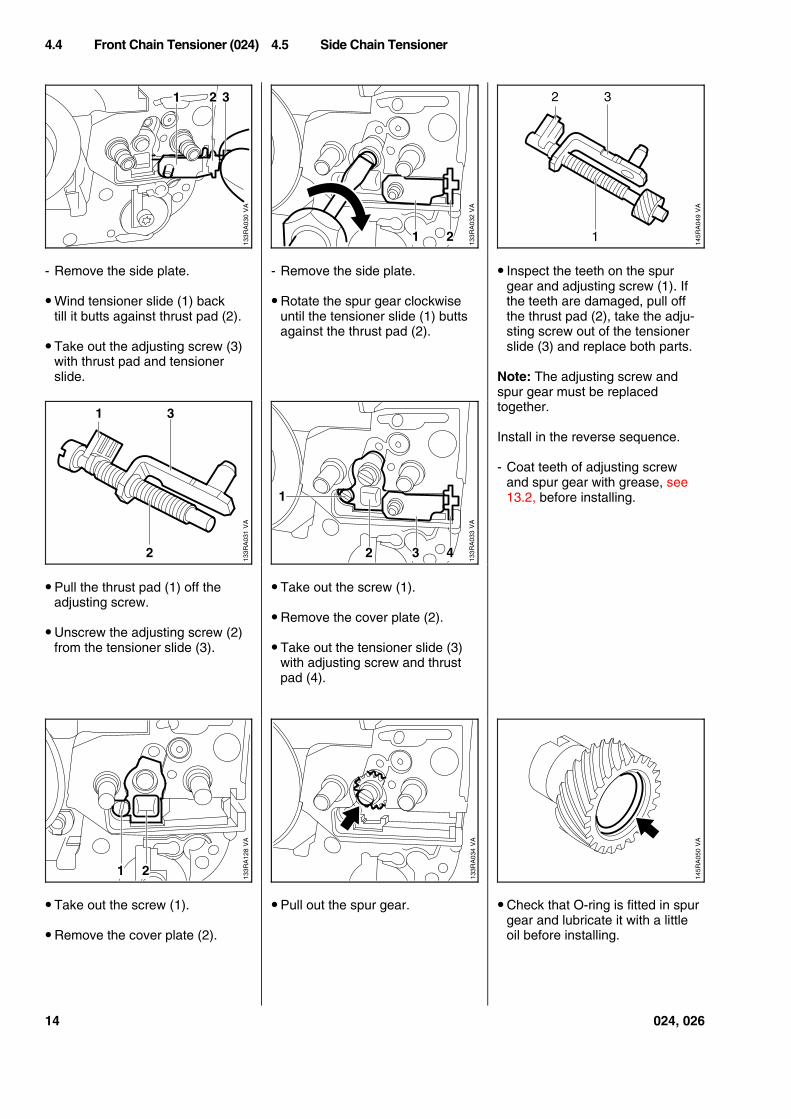
• Carefully tap home the pinsquarely to obtain dimension "a",i.e. 4.3 - 4.7 mm (11/64").
- Install the cylinder - see 5.6.2.
- Install the chain brake - see4.3.3.
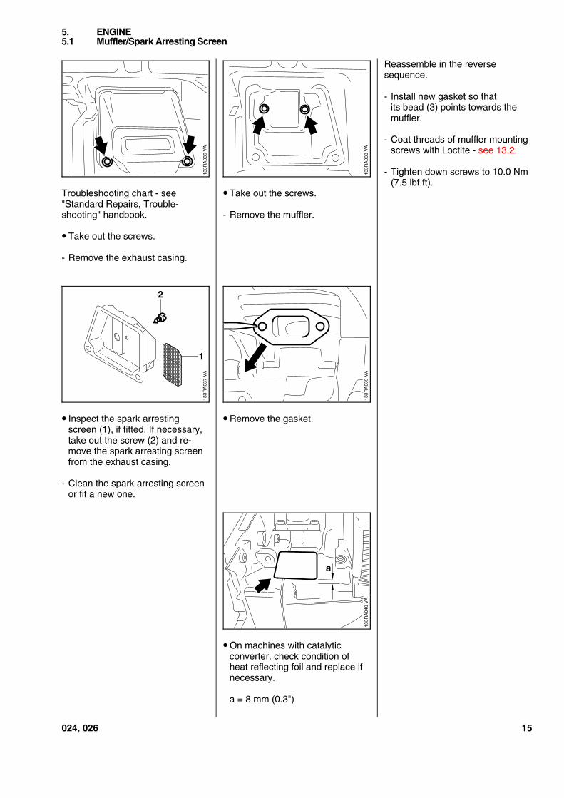
• Use pliers (e.g. pincers) to pullthe pin out of the crankcase.
- Coat the knurled area of the newpin with Loctite, see 13.2, beforeinstallation.
- Position the new pin in the boreso that the knurling on the pinmeshes with the existing knurlingin the bore.
- Carefully tap home the pinsquarely.
4.3.4 Anchor Pin for Brake Spring 4.3.5 Pin for Hand Guard
VA
171R
A03
2
VA
145R
A02
8
a
VA
145R
A02
71
024, 026 13
- Remove the side plate.
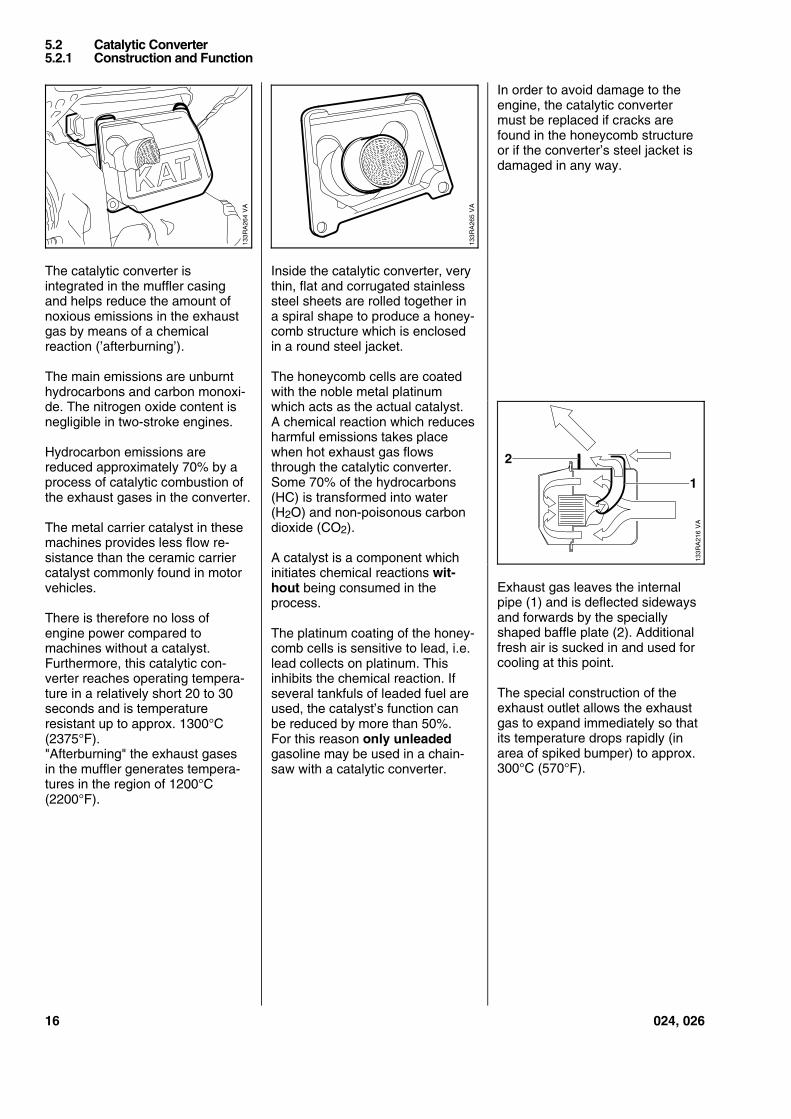
• Wind tensioner slide (1) backtill it butts against thrust pad (2).
• Take out the adjusting screw (3)with thrust pad and tensionerslide.
• Pull the thrust pad (1) off theadjusting screw.
• Unscrew the adjusting screw (2)from the tensioner slide (3).
• Take out the screw (1).
• Remove the cover plate (2).
- Remove the side plate.
• Rotate the spur gear clockwiseuntil the tensioner slide (1) buttsagainst the thrust pad (2).
• Take out the screw (1).
• Remove the cover plate (2).
• Take out the tensioner slide (3)with adjusting screw and thrustpad (4).
• Pull out the spur gear.
• Inspect the teeth on the spurgear and adjusting screw (1). Ifthe teeth are damaged, pull offthe thrust pad (2), take the adju-sting screw out of the tensionerslide (3) and replace both parts.
Note: The adjusting screw andspur gear must be replacedtogether.
Install in the reverse sequence.
- Coat teeth of adjusting screwand spur gear with grease, see13.2, before installing.
• Check that O-ring is fitted in spurgear and lubricate it with a littleoil before installing.
4.4 Front Chain Tensioner (024) 4.5 Side Chain Tensioner
VA
133R
A03
0
1 2 3
VA
133R
A03
2
1 2
VA
145R
A04
9
1
2 3
VA
133R
A03
1
1 3
2
VA
133R
A03
3
1
2 3 4
VA
133R
A12
8
21
VA
133R
A03
4
VA
145R
A05
0
14 024, 026
Troubleshooting chart - see"Standard Repairs, Trouble-shooting" handbook.
• Take out the screws.
- Remove the exhaust casing.
• Inspect the spark arrestingscreen (1), if fitted. If necessary,take out the screw (2) and re-move the spark arresting screenfrom the exhaust casing.
- Clean the spark arresting screenor fit a new one.
• Take out the screws.
- Remove the muffler.
• Remove the gasket.
• On machines with catalyticconverter, check condition ofheat reflecting foil and replace ifnecessary.
a = 8 mm (0.3")
Reassemble in the reversesequence.
- Install new gasket so thatits bead (3) points towards themuffler.
- Coat threads of muffler mountingscrews with Loctite - see 13.2.
- Tighten down screws to 10.0 Nm(7.5 lbf.ft).
5. ENGINE5.1 Muffler/Spark Arresting Screen
133R
A03
8V
A
133R
A03
6V
AV
A13
3RA
037
1
2
VA
133R
A03
9
a
VA
133R
A04
0
024, 026 15
The catalytic converter isintegrated in the muffler casingand helps reduce the amount ofnoxious emissions in the exhaustgas by means of a chemicalreaction (’afterburning’).
The main emissions are unburnthydrocarbons and carbon monoxi-de. The nitrogen oxide content isnegligible in two-stroke engines.
Hydrocarbon emissions arereduced approximately 70% by aprocess of catalytic combustion ofthe exhaust gases in the converter.
The metal carrier catalyst in thesemachines provides less flow re-sistance than the ceramic carriercatalyst commonly found in motorvehicles.
There is therefore no loss ofengine power compared tomachines without a catalyst.Furthermore, this catalytic con-verter reaches operating tempera-ture in a relatively short 20 to 30seconds and is temperatureresistant up to approx. 1300°C(2375°F)."Afterburning" the exhaust gasesin the muffler generates tempera-tures in the region of 1200°C(2200°F).
Inside the catalytic converter, verythin, flat and corrugated stainlesssteel sheets are rolled together ina spiral shape to produce a honey-comb structure which is enclosedin a round steel jacket.
The honeycomb cells are coatedwith the noble metal platinumwhich acts as the actual catalyst.A chemical reaction which reducesharmful emissions takes placewhen hot exhaust gas flowsthrough the catalytic converter.Some 70% of the hydrocarbons(HC) is transformed into water(H2O) and non-poisonous carbondioxide (CO2).
A catalyst is a component whichinitiates chemical reactions wit-hout being consumed in theprocess.
The platinum coating of the honey-comb cells is sensitive to lead, i.e.lead collects on platinum. Thisinhibits the chemical reaction. Ifseveral tankfuls of leaded fuel areused, the catalyst’s function canbe reduced by more than 50%.For this reason only unleadedgasoline may be used in a chain-saw with a catalytic converter.
In order to avoid damage to theengine, the catalytic convertermust be replaced if cracks arefound in the honeycomb structureor if the converter’s steel jacket isdamaged in any way.
Exhaust gas leaves the internalpipe (1) and is deflected sidewaysand forwards by the speciallyshaped baffle plate (2). Additionalfresh air is sucked in and used forcooling at this point.
The special construction of theexhaust outlet allows the exhaustgas to expand immediately so thatits temperature drops rapidly (inarea of spiked bumper) to approx.300°C (570°F).
5.2 Catalytic Converter5.2.1 Construction and Function
VA
133R
A26
4
VA
133R
A26
5
VA
133R
A21
6
2
1
16 024, 026
Defective oil seals and gaskets orcracks in castings are the usualcauses of leaks. Such faults allowsupplementary air to enter theengine and thus upset the fuel-airmixture.
This makes adjustment of theprescribed idle speed difficult, ifnot impossible.
Moreover, the transition from idlespeed to part or full throttle is notsmooth.
The engine can be checkedthoroughly for leaks with thecarburetor and crankcase testerand the vacuum pump.
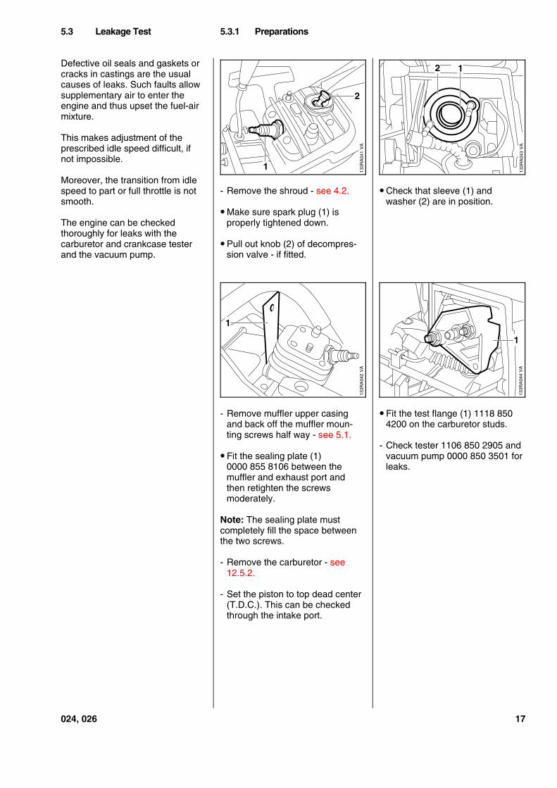
- Remove the shroud - see 4.2.
• Make sure spark plug (1) isproperly tightened down.
• Pull out knob (2) of decompres-sion valve - if fitted.
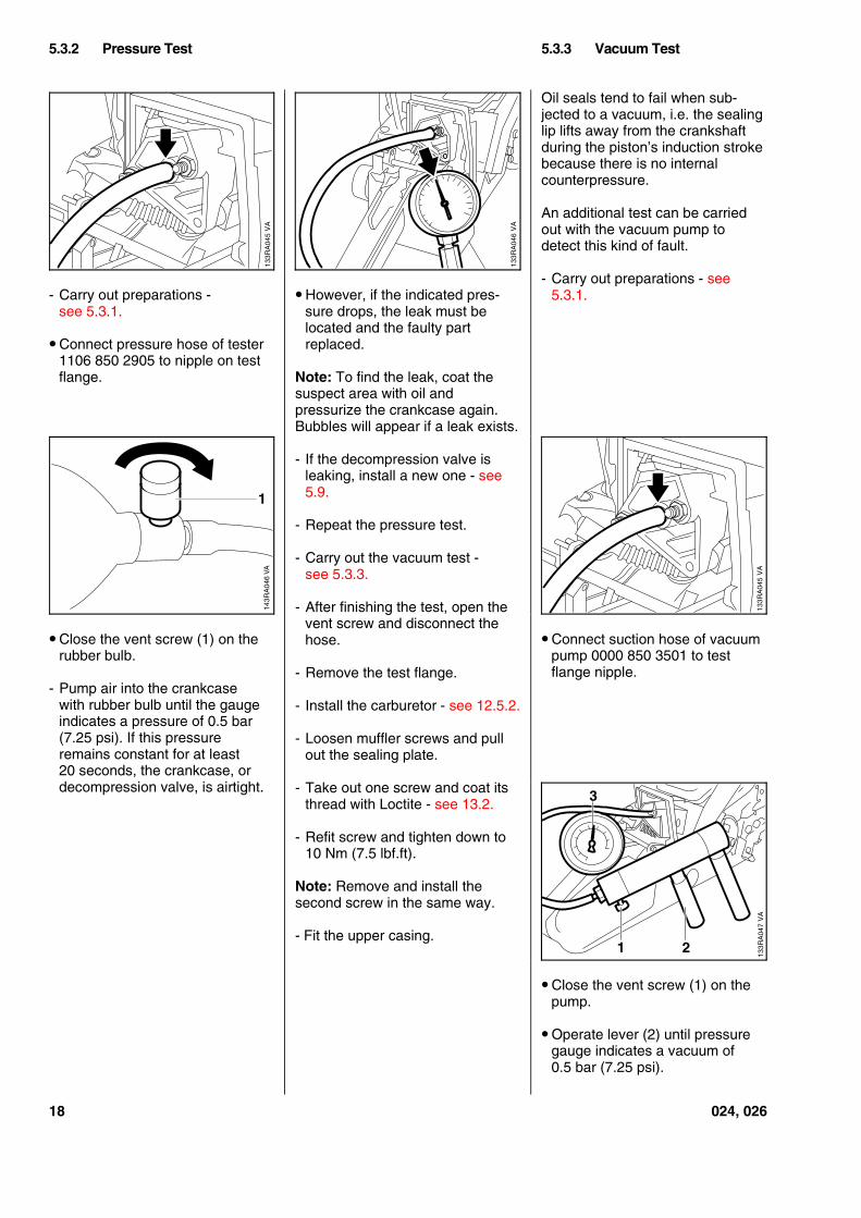
- Remove muffler upper casingand back off the muffler moun-ting screws half way - see 5.1.
• Fit the sealing plate (1)0000 855 8106 between themuffler and exhaust port andthen retighten the screwsmoderately.
Note: The sealing plate mustcompletely fill the space betweenthe two screws.
- Remove the carburetor - see12.5.2.
- Set the piston to top dead center(T.D.C.). This can be checkedthrough the intake port.
• Check that sleeve (1) andwasher (2) are in position.
• Fit the test flange (1) 1118 8504200 on the carburetor studs.
- Check tester 1106 850 2905 andvacuum pump 0000 850 3501 forleaks.
5.3 Leakage Test 5.3.1 Preparations
VA
133R
A04
1
1
2
VA
133R
A04
2
1
VA
133R
A04
3
2 1
VA
133R
A04
4
1
024, 026 17
- Carry out preparations -see 5.3.1.
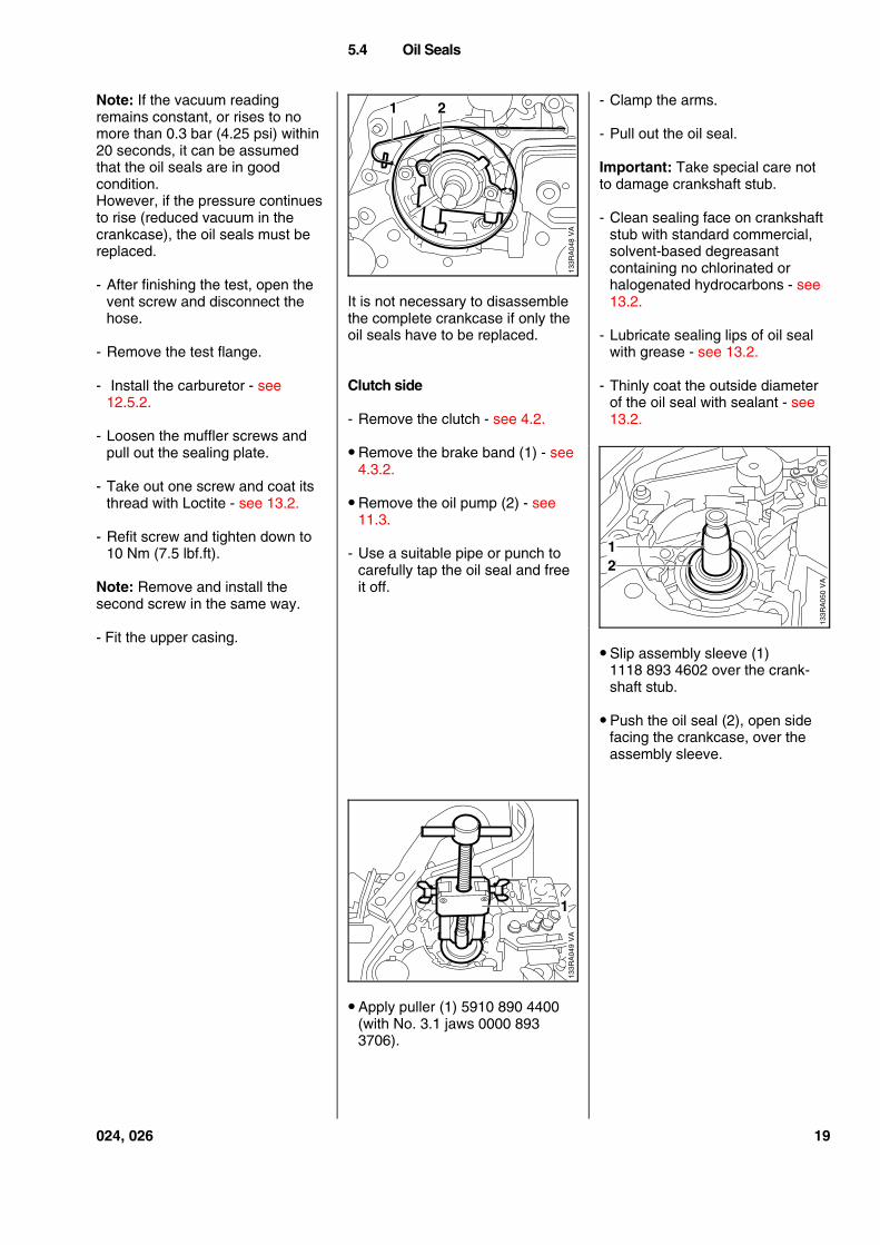
• Connect pressure hose of tester1106 850 2905 to nipple on testflange.
• Close the vent screw (1) on therubber bulb.
- Pump air into the crankcasewith rubber bulb until the gaugeindicates a pressure of 0.5 bar(7.25 psi). If this pressureremains constant for at least20 seconds, the crankcase, ordecompression valve, is airtight.
• However, if the indicated pres-sure drops, the leak must belocated and the faulty partreplaced.
Note: To find the leak, coat thesuspect area with oil andpressurize the crankcase again.Bubbles will appear if a leak exists.
- If the decompression valve isleaking, install a new one - see5.9.
- Repeat the pressure test.
- Carry out the vacuum test -see 5.3.3.
- After finishing the test, open thevent screw and disconnect thehose.
- Remove the test flange.
- Install the carburetor - see 12.5.2.
- Loosen muffler screws and pullout the sealing plate.
- Take out one screw and coat itsthread with Loctite - see 13.2.
- Refit screw and tighten down to10 Nm (7.5 lbf.ft).
Note: Remove and install thesecond screw in the same way.
- Fit the upper casing.
Oil seals tend to fail when sub-jected to a vacuum, i.e. the sealinglip lifts away from the crankshaftduring the piston’s induction strokebecause there is no internalcounterpressure.
An additional test can be carriedout with the vacuum pump todetect this kind of fault.
- Carry out preparations - see5.3.1.
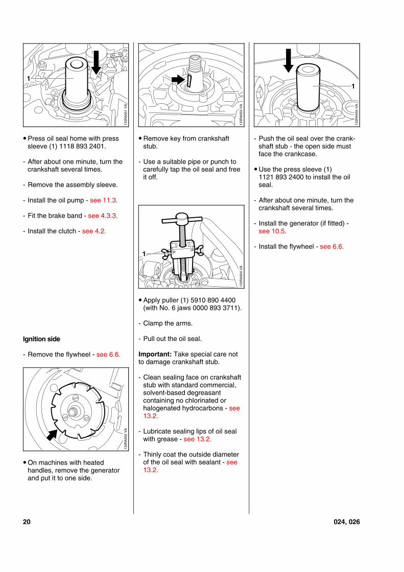
• Connect suction hose of vacuumpump 0000 850 3501 to testflange nipple.
• Close the vent screw (1) on thepump.
• Operate lever (2) until pressuregauge indicates a vacuum of0.5 bar (7.25 psi).
5.3.2 Pressure Test 5.3.3 Vacuum Test
VA
133R
A04
5
VA
133R
A04
6
143R
A04
6 V
A
1
VA
133R
A04
5V
A13
3RA
047
3
1 2
18 024, 026
Note: If the vacuum readingremains constant, or rises to nomore than 0.3 bar (4.25 psi) within20 seconds, it can be assumedthat the oil seals are in goodcondition.However, if the pressure continuesto rise (reduced vacuum in thecrankcase), the oil seals must bereplaced.
- After finishing the test, open thevent screw and disconnect thehose.
- Remove the test flange.
- Install the carburetor - see12.5.2.
- Loosen the muffler screws andpull out the sealing plate.
- Take out one screw and coat itsthread with Loctite - see 13.2.
- Refit screw and tighten down to10 Nm (7.5 lbf.ft).
Note: Remove and install thesecond screw in the same way.
- Fit the upper casing.
It is not necessary to disassemblethe complete crankcase if only theoil seals have to be replaced.
Clutch side
- Remove the clutch - see 4.2.
• Remove the brake band (1) - see4.3.2.
• Remove the oil pump (2) - see11.3.
- Use a suitable pipe or punch tocarefully tap the oil seal and freeit off.
• Apply puller (1) 5910 890 4400(with No. 3.1 jaws 0000 8933706).
- Clamp the arms.
- Pull out the oil seal.
Important: Take special care notto damage crankshaft stub.
- Clean sealing face on crankshaftstub with standard commercial,solvent-based degreasantcontaining no chlorinated orhalogenated hydrocarbons - see13.2.
- Lubricate sealing lips of oil sealwith grease - see 13.2.
- Thinly coat the outside diameterof the oil seal with sealant - see13.2.
• Slip assembly sleeve (1)1118 893 4602 over the crank-shaft stub.
• Push the oil seal (2), open sidefacing the crankcase, over theassembly sleeve.
5.4 Oil Seals
21
VA
133R
A04
8
VA
133R
A05
0
21
133R
A04
9V
A
1
024, 026 19
• Press oil seal home with presssleeve (1) 1118 893 2401.
- After about one minute, turn thecrankshaft several times.
- Remove the assembly sleeve.
- Install the oil pump - see 11.3.
- Fit the brake band - see 4.3.3.
- Install the clutch - see 4.2.
Ignition side
- Remove the flywheel - see 6.6.
• On machines with heatedhandles, remove the generatorand put it to one side.
• Remove key from crankshaftstub.
- Use a suitable pipe or punch tocarefully tap the oil seal and freeit off.
• Apply puller (1) 5910 890 4400(with No. 6 jaws 0000 893 3711).
- Clamp the arms.
- Pull out the oil seal.
Important: Take special care notto damage crankshaft stub.
- Clean sealing face on crankshaftstub with standard commercial,solvent-based degreasantcontaining no chlorinated orhalogenated hydrocarbons - see13.2.
- Lubricate sealing lips of oil sealwith grease - see 13.2.
- Thinly coat the outside diameterof the oil seal with sealant - see13.2.
- Push the oil seal over the crank-shaft stub - the open side mustface the crankcase.
• Use the press sleeve (1)1121 893 2400 to install the oilseal.
- After about one minute, turn thecrankshaft several times.
- Install the generator (if fitted) -see 10.5.
- Install the flywheel - see 6.6.
VA
133R
A05
1
1
VA
133R
A05
3
1
133R
A05
5V
A
1
VA
133R
A05
4
133R
A05
2V
A
20 024, 026
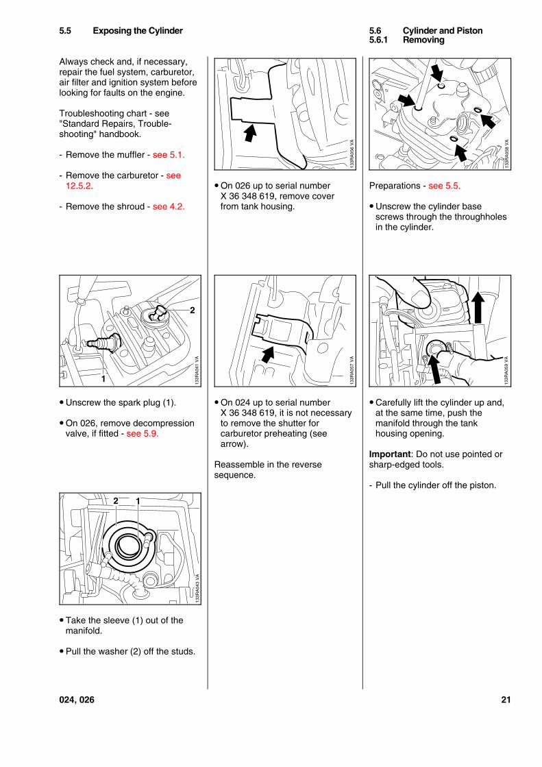
Always check and, if necessary,repair the fuel system, carburetor,air filter and ignition system beforelooking for faults on the engine.
Troubleshooting chart - see"Standard Repairs, Trouble-shooting" handbook.
- Remove the muffler - see 5.1.
- Remove the carburetor - see12.5.2.
- Remove the shroud - see 4.2.
• Unscrew the spark plug (1).
• On 026, remove decompressionvalve, if fitted - see 5.9.
• Take the sleeve (1) out of themanifold.
• Pull the washer (2) off the studs.
• On 026 up to serial numberX 36 348 619, remove coverfrom tank housing.
• On 024 up to serial numberX 36 348 619, it is not necessaryto remove the shutter forcarburetor preheating (seearrow).
Reassemble in the reversesequence.
Preparations - see 5.5.
• Unscrew the cylinder basescrews through the throughholesin the cylinder.
• Carefully lift the cylinder up and,at the same time, push themanifold through the tankhousing opening.
Important: Do not use pointed orsharp-edged tools.
- Pull the cylinder off the piston.
5.5 Exposing the Cylinder 5.6 Cylinder and Piston5.6.1 Removing
VA
133R
A04
1
1
2
VA
133R
A04
3
2 1
133R
A05
6V
A13
3RA
057
VA
VA
133R
A05
8V
A13
3RA
059
024, 026 21
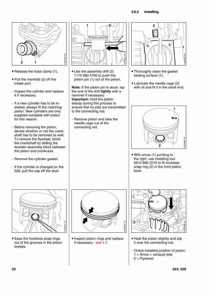
• Release the hose clamp (1).
• Pull the manifold (2) off theintake port.
- Inspect the cylinder and replaceit if necessary.
- If a new cylinder has to be in-stalled, always fit the matchingpiston. New cylinders are onlysupplied complete with pistonfor this reason.
- Before removing the piston,decide whether or not the crank-shaft has to be removed as well.To remove the flywheel, blockthe crankshaft by sliding thewooden assembly block betweenthe piston and crankcase.
- Remove the cylinder gasket.
- If the cylinder is changed on the026, pull the cap off the stud.
• Ease the hookless snap ringsout of the grooves in the pistonbosses.
• Use the assembly drift (2)1110 893 4700 to push thepiston pin (1) out of the piston.
Note: If the piston pin is stuck, tapthe end of the drift lightly with ahammer if necessary.Important: Hold the pistonsteady during this process toensure that no jolts are transmittedto the connecting rod.
- Remove piston and take theneedle cage out of theconnecting rod.
• Inspect piston rings and replaceif necessary - see 5.7.
• Thoroughly clean the gasketseating surface (1).
• Lubricate the needle cage (2)with oil and fit it in the small end.
• With arrow (1) pointing tothe right, use installing tool5910 890 2210 to fit hooklesssnap ring (2) in the front pistonboss.
• Heat the piston slightly and slipit over the connecting rod.
- Check installed position of piston:1 = Arrow = exhaust side2 = Flywheel
5.6.2 Installing
VA
133R
A06
012
VA
133R
A06
2
21
1
VA
133R
A06
4
2
VA
133R
A06
5
1
2
VA
133R
A06
1
VA
133R
A06
3
1
2 VA
133R
A06
6
22 024, 026
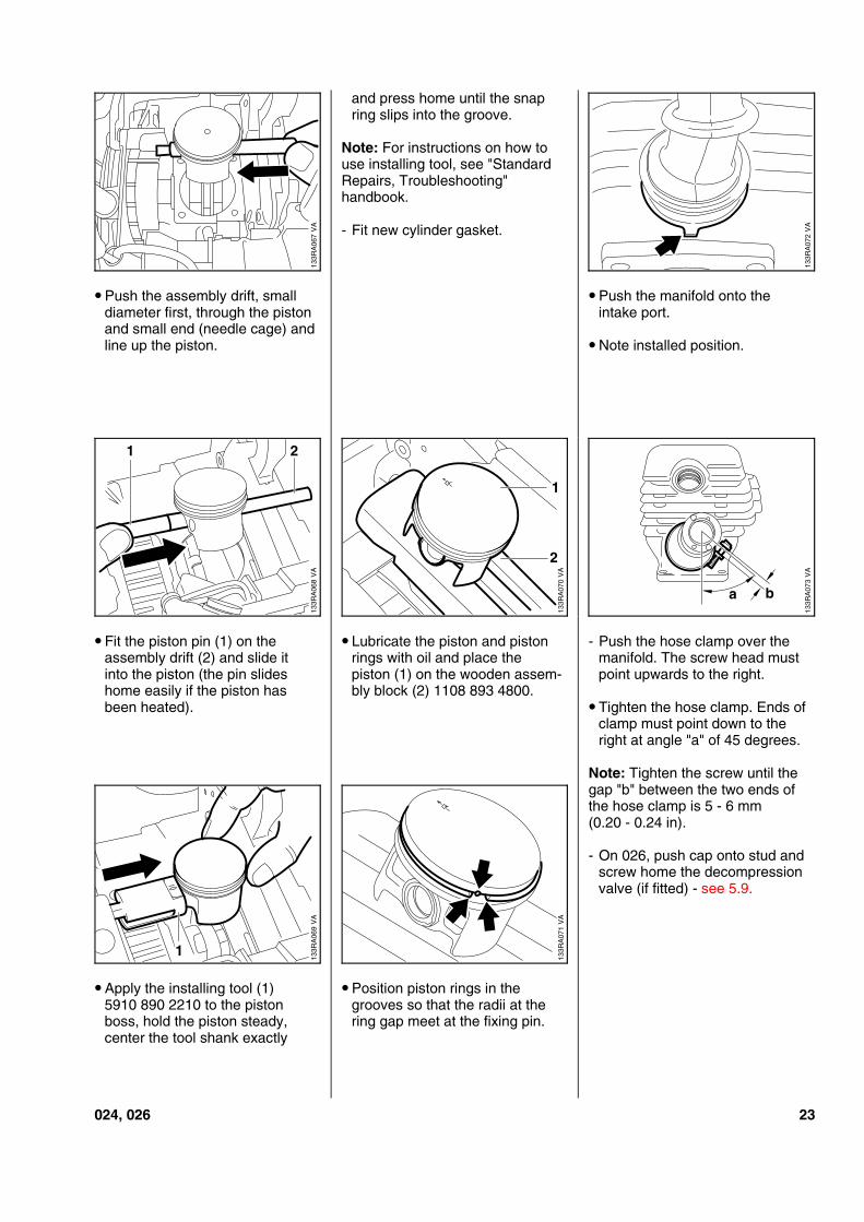
• Push the assembly drift, smalldiameter first, through the pistonand small end (needle cage) andline up the piston.
• Fit the piston pin (1) on theassembly drift (2) and slide itinto the piston (the pin slideshome easily if the piston hasbeen heated).
• Apply the installing tool (1)5910 890 2210 to the pistonboss, hold the piston steady,center the tool shank exactly
and press home until the snapring slips into the groove.
Note: For instructions on how touse installing tool, see "StandardRepairs, Troubleshooting"handbook.
- Fit new cylinder gasket.
• Lubricate the piston and pistonrings with oil and place thepiston (1) on the wooden assem-bly block (2) 1108 893 4800.
• Position piston rings in thegrooves so that the radii at thering gap meet at the fixing pin.
• Push the manifold onto theintake port.
• Note installed position.
- Push the hose clamp over themanifold. The screw head mustpoint upwards to the right.
• Tighten the hose clamp. Ends ofclamp must point down to theright at angle "a" of 45 degrees.
Note: Tighten the screw until thegap "b" between the two ends ofthe hose clamp is 5 - 6 mm(0.20 - 0.24 in).
- On 026, push cap onto stud andscrew home the decompressionvalve (if fitted) - see 5.9.
VA
133R
A06
7V
A13
3RA
068
21
VA
133R
A06
9
1
VA
133R
A07
0
1
2V
A13
3RA
071
VA
133R
A07
2V
A13
3RA
073
a b
024, 026 23
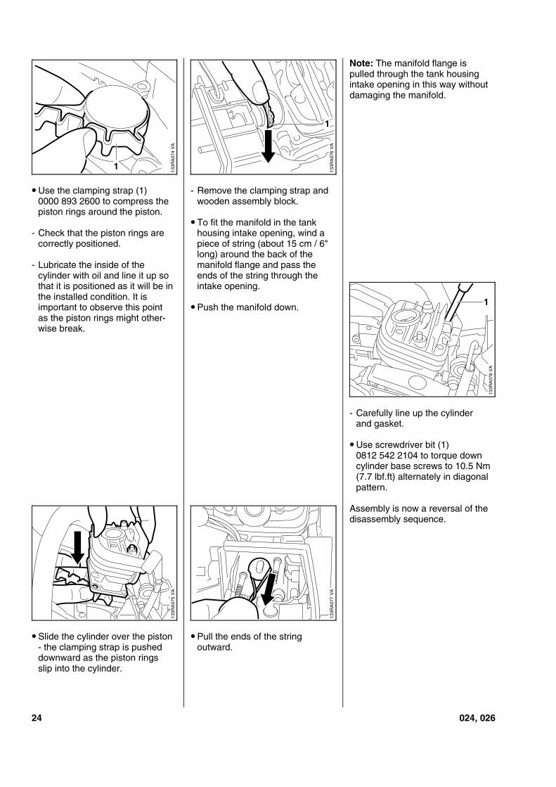
• Use the clamping strap (1)0000 893 2600 to compress thepiston rings around the piston.
- Check that the piston rings arecorrectly positioned.
- Lubricate the inside of thecylinder with oil and line it up sothat it is positioned as it will be inthe installed condition. It isimportant to observe this pointas the piston rings might other-wise break.
• Slide the cylinder over the piston- the clamping strap is pusheddownward as the piston ringsslip into the cylinder.
- Remove the clamping strap andwooden assembly block.
• To fit the manifold in the tankhousing intake opening, wind apiece of string (about 15 cm / 6"long) around the back of themanifold flange and pass theends of the string through theintake opening.
• Push the manifold down.
• Pull the ends of the stringoutward.
Note: The manifold flange ispulled through the tank housingintake opening in this way withoutdamaging the manifold.
- Carefully line up the cylinderand gasket.
• Use screwdriver bit (1)0812 542 2104 to torque downcylinder base screws to 10.5 Nm(7.7 lbf.ft) alternately in diagonalpattern.
Assembly is now a reversal of thedisassembly sequence.
VA
133R
A07
41
VA
133R
A07
6
1
VA
133R
A07
8
1
VA
133R
A07
7
133R
A07
5V
A
24 024, 026
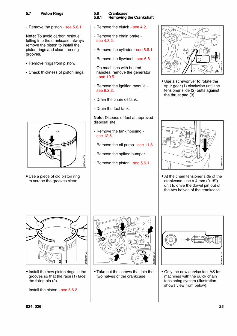
- Remove the piston - see 5.6.1.
Note: To avoid carbon residuefalling into the crankcase, alwaysremove the piston to install thepiston rings and clean the ringgrooves.
- Remove rings from piston.
- Check thickness of piston rings.
• Use a piece of old piston ringto scrape the grooves clean.
• Install the new piston rings in thegrooves so that the radii (1) facethe fixing pin (2).
- Install the piston - see 5.6.2.
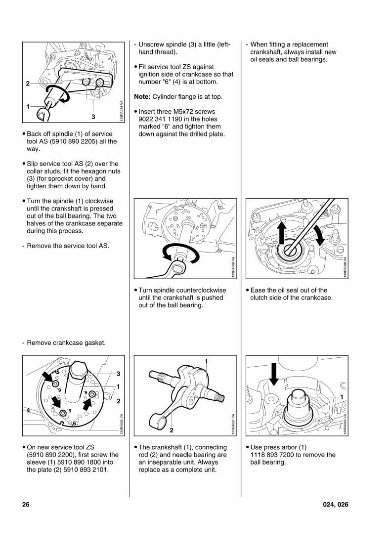
- Remove the clutch - see 4.2.
- Remove the chain brake -see 4.3.2.
- Remove the cylinder - see 5.6.1.
- Remove the flywheel - see 6.6.
- On machines with heatedhandles, remove the generator- see 10.5.
- Remove the ignition module -see 6.2.2.
- Drain the chain oil tank.
- Drain the fuel tank.
Note: Dispose of fuel at approveddisposal site.
- Remove the tank housing -see 12.8.
- Remove the oil pump - see 11.3.
- Remove the spiked bumper.
- Remove the piston - see 5.6.1.
• Take out the screws that join thetwo halves of the crankcase.
• Use a screwdriver to rotate thespur gear (1) clockwise until thetensioner slide (2) butts againstthe thrust pad (3).
• At the chain tensioner side of thecrankcase, use a 4 mm (0.15")drift to drive the dowel pin out ofthe two halves of the crankcase.
• Only the new service tool AS formachines with the quick chaintensioning system (illustrationshows view from below).
5.7 Piston Rings 5.8 Crankcase5.8.1 Removing the Crankshaft
VA
133R
A08
1
2 31
145R
A09
8V
A
VA
133R
A08
2
VA
133R
A07
9
2 11
VA
133R
A08
3
VA
133R
A08
0
024, 026 25
• Back off spindle (1) of servicetool AS (5910 890 2205) all theway.
• Slip service tool AS (2) over thecollar studs, fit the hexagon nuts(3) (for sprocket cover) andtighten them down by hand.
• Turn the spindle (1) clockwiseuntil the crankshaft is pressedout of the ball bearing. The twohalves of the crankcase separateduring this process.
- Remove the service tool AS.
- Remove crankcase gasket.
• On new service tool ZS(5910 890 2200), first screw thesleeve (1) 5910 890 1800 intothe plate (2) 5910 893 2101.
- Unscrew spindle (3) a little (left-hand thread).
• Fit service tool ZS againstignition side of crankcase so thatnumber "6" (4) is at bottom.
Note: Cylinder flange is at top.
• Insert three M5x72 screws9022 341 1190 in the holesmarked "6" and tighten themdown against the drilled plate.
• Turn spindle counterclockwiseuntil the crankshaft is pushedout of the ball bearing.
• The crankshaft (1), connectingrod (2) and needle bearing arean inseparable unit. Alwaysreplace as a complete unit.
- When fitting a replacementcrankshaft, always install newoil seals and ball bearings.
• Ease the oil seal out of theclutch side of the crankcase.
• Use press arbor (1)1118 893 7200 to remove theball bearing.
VA
133R
A08
4
2
3
1
VA
133R
A08
6
VA
133R
A08
8
6.
6.
VA
133R
A08
5
2
1
3
4
6. 6.
133R
A08
7V
A
1
2
VA
133R
A08
9
1
26 024, 026
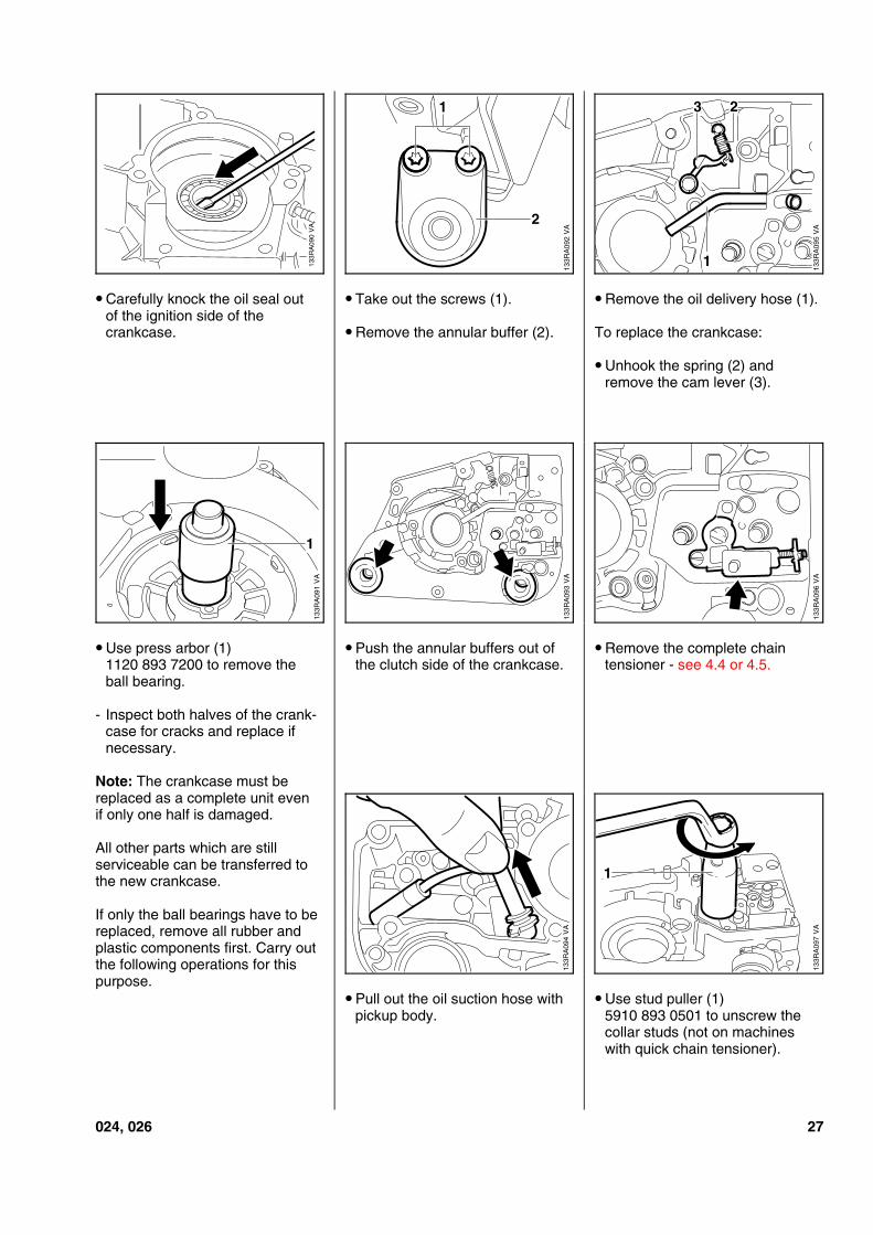
• Carefully knock the oil seal outof the ignition side of thecrankcase.
• Use press arbor (1)1120 893 7200 to remove theball bearing.
- Inspect both halves of the crank-case for cracks and replace ifnecessary.
Note: The crankcase must bereplaced as a complete unit evenif only one half is damaged.
All other parts which are stillserviceable can be transferred tothe new crankcase.
If only the ball bearings have to bereplaced, remove all rubber andplastic components first. Carry outthe following operations for thispurpose.
• Take out the screws (1).
• Remove the annular buffer (2).
• Push the annular buffers out ofthe clutch side of the crankcase.
• Pull out the oil suction hose withpickup body.
• Remove the oil delivery hose (1).
To replace the crankcase:
• Unhook the spring (2) andremove the cam lever (3).
• Remove the complete chaintensioner - see 4.4 or 4.5.
• Use stud puller (1)5910 893 0501 to unscrew thecollar studs (not on machineswith quick chain tensioner).
VA
133R
A09
0 VA
133R
A09
2
2
1
VA
133R
A09
5
23
1
VA
133R
A09
1
1V
A13
3RA
093
VA
133R
A09
6
VA
133R
A09
4
VA
133R
A09
7
1
024, 026 27
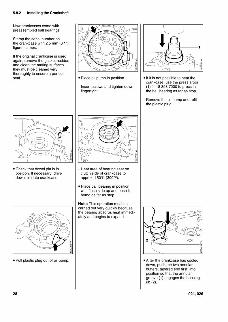
New crankcases come withpreassembled ball bearings.
Stamp the serial number onthe crankcase with 2.5 mm (0.1")figure stamps.
If the original crankcase is usedagain, remove the gasket residueand clean the mating surfaces -they must be cleaned verythoroughly to ensure a perfectseal.
• Check that dowel pin is inposition. If necessary, drivedowel pin into crankcase.
• Pull plastic plug out of oil pump.
• Place oil pump in position.
- Insert screws and tighten downfingertight.
- Heat area of bearing seat onclutch side of crankcase toapprox. 150°C (300°F).
• Place ball bearing in positionwith flush side up and push ithome as far as stop.
Note: This operation must becarried out very quickly becausethe bearing absorbs heat immedi-ately and begins to expand.
• If it is not possible to heat thecrankcase, use the press arbor(1) 1118 893 7200 to press inthe ball bearing as far as stop.
- Remove the oil pump and refitthe plastic plug.
• After the crankcase has cooleddown, push the two annularbuffers, tapered end first, intoposition so that the annulargroove (1) engages the housingrib (2).
5.8.2 Installing the Crankshaft
133R
A10
2V
A
1
VA
133R
A10
1
VA
133R
A09
9
VA
133R
A10
3
1
2
VA
133R
A10
0
28 024, 026
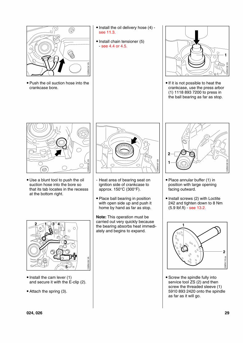
• Push the oil suction hose into thecrankcase bore.
• Use a blunt tool to push the oilsuction hose into the bore sothat its tab locates in the recesssat the bottom right.
• Install the cam lever (1)and secure it with the E-clip (2).
• Attach the spring (3).
• Install the oil delivery hose (4) -see 11.3.
• Install chain tensioner (5)- see 4.4 or 4.5.
- Heat area of bearing seat onignition side of crankcase toapprox. 150°C (300°F).
• Place ball bearing in positionwith open side up and push ithome by hand as far as stop.
Note: This operation must becarried out very quickly becausethe bearing absorbs heat immedi-ately and begins to expand.
• If it is not possible to heat thecrankcase, use the press arbor(1) 1118 893 7200 to press inthe ball bearing as far as stop.
• Place annular buffer (1) inposition with large openingfacing outward.
• Install screws (2) with Loctite242 and tighten down to 8 Nm(5.9 lbf.ft) - see 13.2.
• Screw the spindle fully intoservice tool ZS (2) and thenscrew the threaded sleeve (1)5910 893 2420 onto the spindleas far as it will go.
VA
133R
A10
4
VA
133R
A10
8
1
VA
133R
A10
5
VA
133R
A10
7
VA
133R
A10
9
2
1
VA
133R
A10
6
2 1 43
5 338R
A11
61
VA
2
024, 026 29
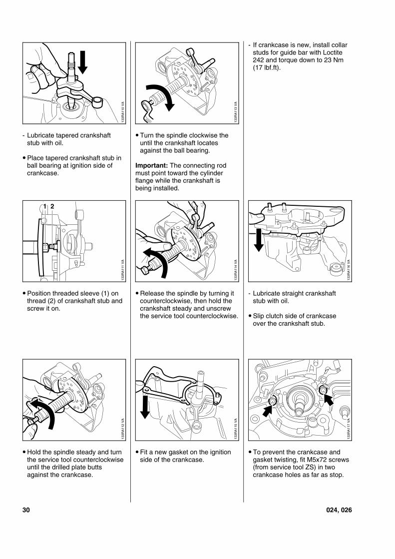
- Lubricate tapered crankshaftstub with oil.
• Place tapered crankshaft stub inball bearing at ignition side ofcrankcase.
• Position threaded sleeve (1) onthread (2) of crankshaft stub andscrew it on.
• Hold the spindle steady and turnthe service tool counterclockwiseuntil the drilled plate buttsagainst the crankcase.
• Turn the spindle clockwise theuntil the crankshaft locatesagainst the ball bearing.
Important: The connecting rodmust point toward the cylinderflange while the crankshaft isbeing installed.
• Release the spindle by turning itcounterclockwise, then hold thecrankshaft steady and unscrewthe service tool counterclockwise.
• Fit a new gasket on the ignitionside of the crankcase.
- If crankcase is new, install collarstuds for guide bar with Loctite242 and torque down to 23 Nm(17 lbf.ft).
- Lubricate straight crankshaftstub with oil.
• Slip clutch side of crankcaseover the crankshaft stub.
• To prevent the crankcase andgasket twisting, fit M5x72 screws(from service tool ZS) in twocrankcase holes as far as stop.
VA
133R
A11
0
VA
133R
A11
3
VA
133R
A11
1
21
VA
133R
A11
4
VA
133R
A11
6
VA
133R
A11
2
VA
133R
A11
5
VA
133R
A11
7
30 024, 026
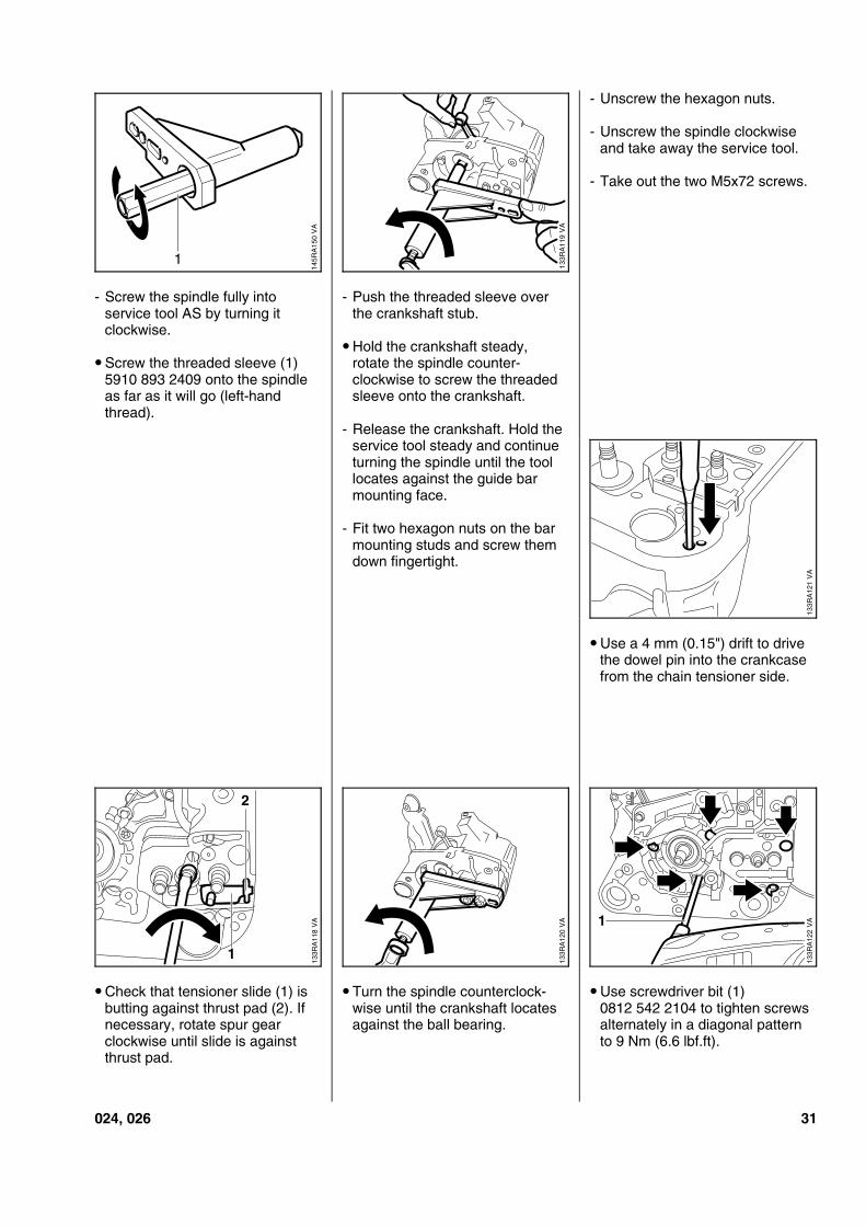
- Screw the spindle fully intoservice tool AS by turning itclockwise.
• Screw the threaded sleeve (1)5910 893 2409 onto the spindleas far as it will go (left-handthread).
• Check that tensioner slide (1) isbutting against thrust pad (2). Ifnecessary, rotate spur gearclockwise until slide is againstthrust pad.
- Push the threaded sleeve overthe crankshaft stub.
• Hold the crankshaft steady,rotate the spindle counter-clockwise to screw the threadedsleeve onto the crankshaft.
- Release the crankshaft. Hold theservice tool steady and continueturning the spindle until the toollocates against the guide barmounting face.
- Fit two hexagon nuts on the barmounting studs and screw themdown fingertight.
• Turn the spindle counterclock-wise until the crankshaft locatesagainst the ball bearing.
- Unscrew the hexagon nuts.
- Unscrew the spindle clockwiseand take away the service tool.
- Take out the two M5x72 screws.
• Use a 4 mm (0.15") drift to drivethe dowel pin into the crankcasefrom the chain tensioner side.
• Use screwdriver bit (1)0812 542 2104 to tighten screwsalternately in a diagonal patternto 9 Nm (6.6 lbf.ft).
1
145R
A15
0 V
A VA
133R
A11
9
VA
133R
A12
1
VA
133R
A11
8
1
2
VA
133R
A12
0
1 VA
133R
A12
2
024, 026 31
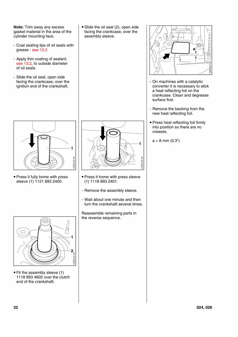
Note: Trim away any excessgasket material in the area of thecylinder mounting face.
- Coat sealing lips of oil seals withgrease - see 13.2.
- Apply thin coating of sealant,see 13.2, to outside diameterof oil seals.
- Slide the oil seal, open sidefacing the crankcase, over theignition end of the crankshaft.
• Press it fully home with presssleeve (1) 1121 893 2400.
• Fit the assembly sleeve (1)1118 893 4602 over the clutchend of the crankshaft.
• Slide the oil seal (2), open sidefacing the crankcase, over theassembly sleeve.
• Press it home with press sleeve(1) 1118 893 2401.
- Remove the assembly sleeve.
- Wait about one minute and thenturn the crankshaft several times.
Reassemble remaining parts inthe reverse sequence.
- On machines with a catalyticconverter it is necessary to sticka heat reflecting foil on thecrankcase. Clean and degreasesurface first.
- Remove the backing from thenew heat reflecting foil.
• Press heat reflecting foil firmlyinto position so there are nocreases.
a = 8 mm (0.3")
a
VA
133R
A04
0
133R
A12
3V
A
1
VA
133R
A12
51
VA
133R
A12
4
1
2
32 024, 026
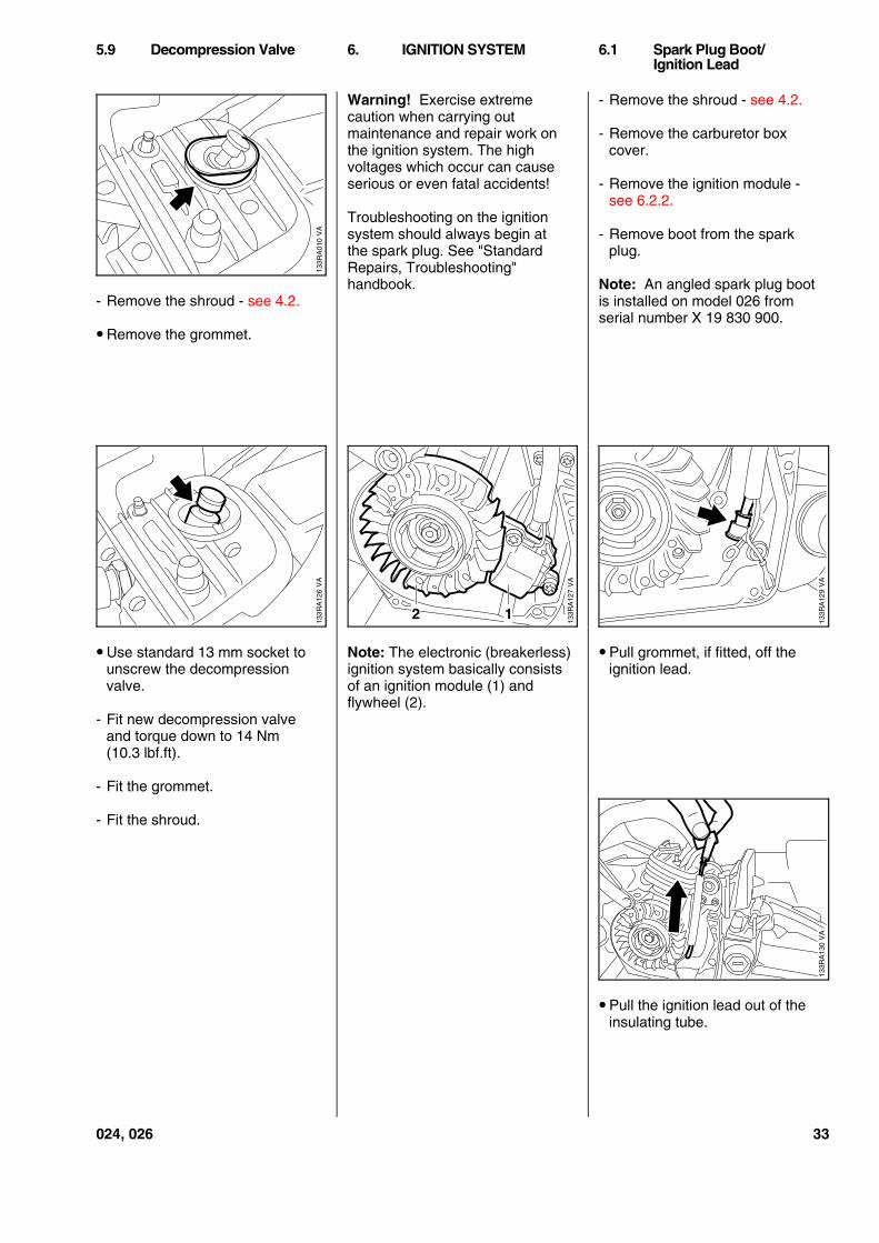
- Remove the shroud - see 4.2.
• Remove the grommet.
• Use standard 13 mm socket tounscrew the decompressionvalve.
- Fit new decompression valveand torque down to 14 Nm(10.3 lbf.ft).
- Fit the grommet.
- Fit the shroud.
Warning! Exercise extremecaution when carrying outmaintenance and repair work onthe ignition system. The highvoltages which occur can causeserious or even fatal accidents!
Troubleshooting on the ignitionsystem should always begin atthe spark plug. See "StandardRepairs, Troubleshooting"handbook.
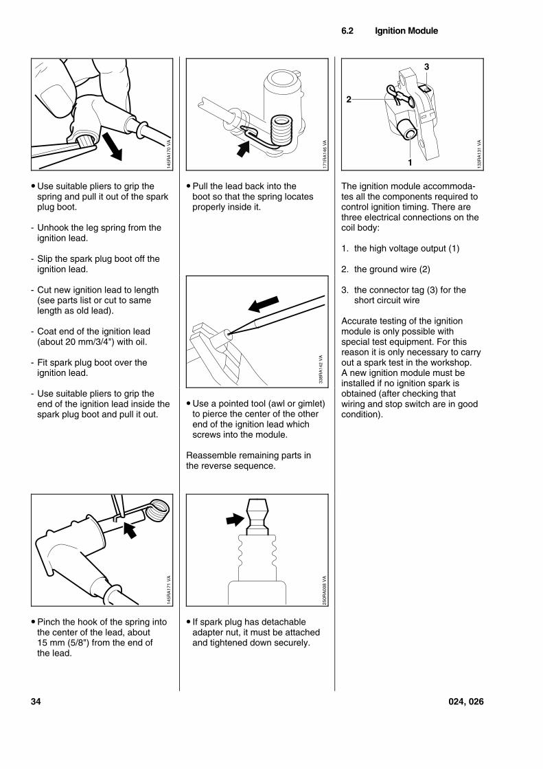
Note: The electronic (breakerless)ignition system basically consistsof an ignition module (1) andflywheel (2).
- Remove the shroud - see 4.2.
- Remove the carburetor boxcover.
- Remove the ignition module -see 6.2.2.
- Remove boot from the sparkplug.
Note: An angled spark plug bootis installed on model 026 fromserial number X 19 830 900.
• Pull grommet, if fitted, off theignition lead.
• Pull the ignition lead out of theinsulating tube.
5.9 Decompression Valve 6. IGNITION SYSTEM 6.1 Spark Plug Boot/Ignition Lead
VA
133R
A01
0V
A13
3RA
126
2 1
VA
133R
A12
7
VA
133R
A12
9V
A13
3RA
130
024, 026 33
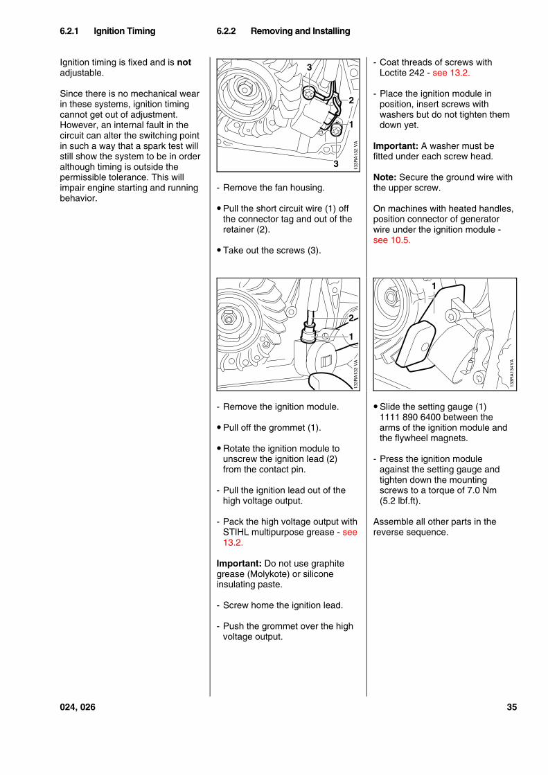
• Use suitable pliers to grip thespring and pull it out of the sparkplug boot.
- Unhook the leg spring from theignition lead.
- Slip the spark plug boot off theignition lead.
- Cut new ignition lead to length(see parts list or cut to samelength as old lead).
- Coat end of the ignition lead(about 20 mm/3/4") with oil.
- Fit spark plug boot over theignition lead.
- Use suitable pliers to grip theend of the ignition lead inside thespark plug boot and pull it out.
• Pinch the hook of the spring intothe center of the lead, about15 mm (5/8") from the end ofthe lead.
• Pull the lead back into theboot so that the spring locatesproperly inside it.
• Use a pointed tool (awl or gimlet)to pierce the center of the otherend of the ignition lead whichscrews into the module.
Reassemble remaining parts inthe reverse sequence.
• If spark plug has detachableadapter nut, it must be attachedand tightened down securely.
The ignition module accommoda-tes all the components required tocontrol ignition timing. There arethree electrical connections on thecoil body:
1. the high voltage output (1)
2. the ground wire (2)
3. the connector tag (3) for theshort circuit wire
Accurate testing of the ignitionmodule is only possible withspecial test equipment. For thisreason it is only necessary to carryout a spark test in the workshop.A new ignition module must beinstalled if no ignition spark isobtained (after checking thatwiring and stop switch are in goodcondition).
6.2 Ignition Module
VA
145R
A17
0
VA
171R
A14
6
VA
133R
A13
1
2
1
3
338R
A14
2 V
A
VA
145R
A17
1
VA
250R
A00
8
34 024, 026
Ignition timing is fixed and is notadjustable.
Since there is no mechanical wearin these systems, ignition timingcannot get out of adjustment.However, an internal fault in thecircuit can alter the switching pointin such a way that a spark test willstill show the system to be in orderalthough timing is outside thepermissible tolerance. This willimpair engine starting and runningbehavior.
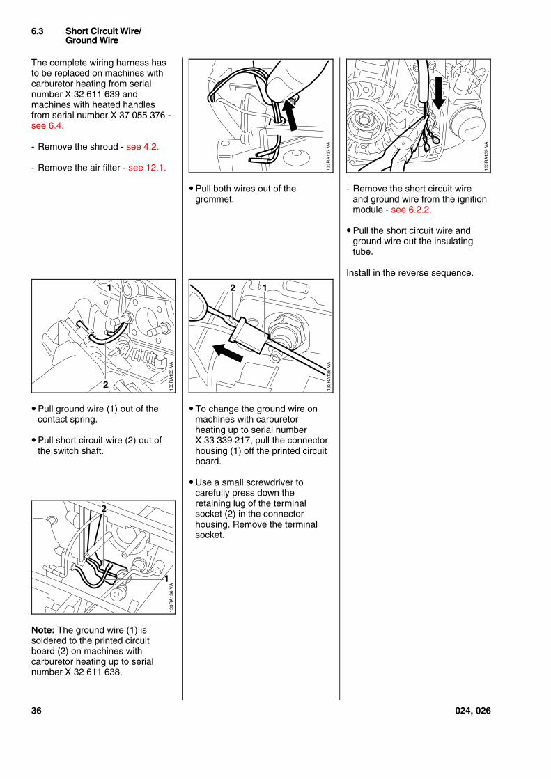
- Remove the fan housing.
• Pull the short circuit wire (1) offthe connector tag and out of theretainer (2).
• Take out the screws (3).
- Remove the ignition module.
• Pull off the grommet (1).
• Rotate the ignition module tounscrew the ignition lead (2)from the contact pin.
- Pull the ignition lead out of thehigh voltage output.
- Pack the high voltage output withSTIHL multipurpose grease - see13.2.
Important: Do not use graphitegrease (Molykote) or siliconeinsulating paste.
- Screw home the ignition lead.
- Push the grommet over the highvoltage output.
- Coat threads of screws withLoctite 242 - see 13.2.
- Place the ignition module inposition, insert screws withwashers but do not tighten themdown yet.
Important: A washer must befitted under each screw head.
Note: Secure the ground wire withthe upper screw.
On machines with heated handles,position connector of generatorwire under the ignition module -see 10.5.
• Slide the setting gauge (1)1111 890 6400 between thearms of the ignition module andthe flywheel magnets.
- Press the ignition moduleagainst the setting gauge andtighten down the mountingscrews to a torque of 7.0 Nm(5.2 lbf.ft).
Assemble all other parts in thereverse sequence.
6.2.1 Ignition Timing 6.2.2 Removing and Installing
VA
133R
A13
2
3
1
2
3
VA
133R
A13
3
2
1
VA
133R
A13
4
1
024, 026 35
The complete wiring harness hasto be replaced on machines withcarburetor heating from serialnumber X 32 611 639 andmachines with heated handlesfrom serial number X 37 055 376 -see 6.4.
- Remove the shroud - see 4.2.
- Remove the air filter - see 12.1.
• Pull ground wire (1) out of thecontact spring.
• Pull short circuit wire (2) out ofthe switch shaft.
Note: The ground wire (1) issoldered to the printed circuitboard (2) on machines withcarburetor heating up to serialnumber X 32 611 638.
• Pull both wires out of thegrommet.
• To change the ground wire onmachines with carburetorheating up to serial numberX 33 339 217, pull the connectorhousing (1) off the printed circuitboard.
• Use a small screwdriver tocarefully press down theretaining lug of the terminalsocket (2) in the connectorhousing. Remove the terminalsocket.
- Remove the short circuit wireand ground wire from the ignitionmodule - see 6.2.2.
• Pull the short circuit wire andground wire out the insulatingtube.
Install in the reverse sequence.
6.3 Short Circuit Wire/Ground Wire
VA
133R
A13
7
VA
133R
A13
9
VA
133R
A13
5
1
2
133R
A13
8
1
VA
2
VA
133R
A13
6
1
2
36 024, 026
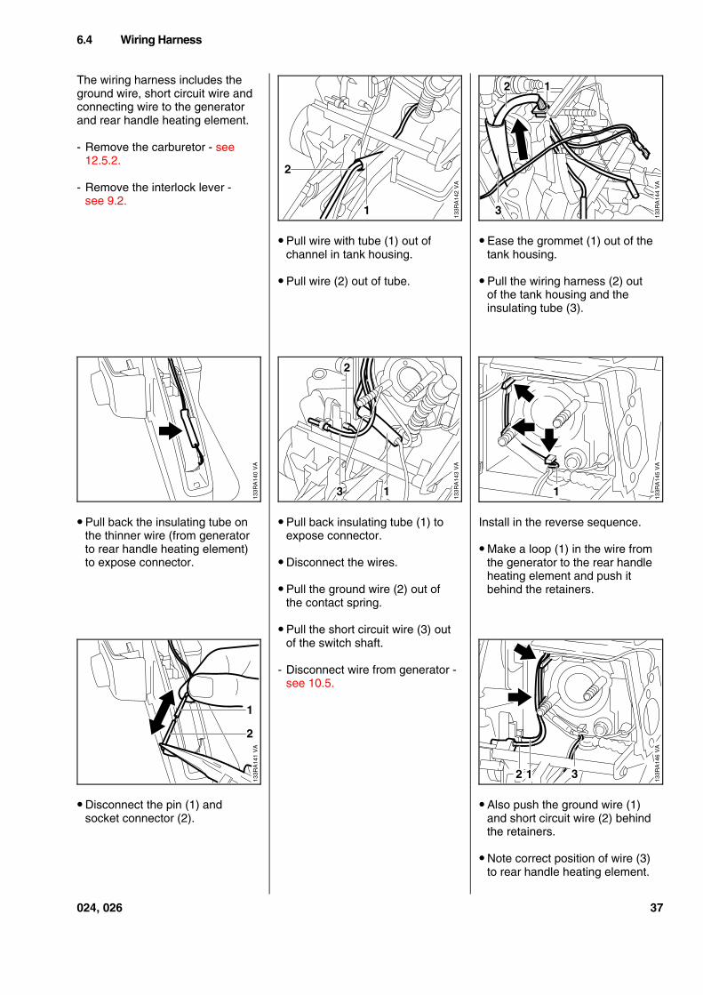
The wiring harness includes theground wire, short circuit wire andconnecting wire to the generatorand rear handle heating element.
- Remove the carburetor - see12.5.2.
- Remove the interlock lever -see 9.2.
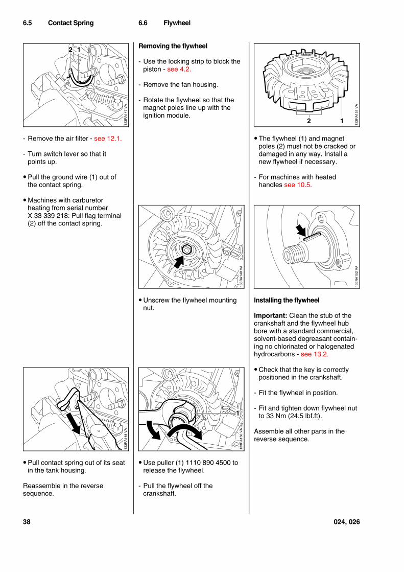
• Pull back the insulating tube onthe thinner wire (from generatorto rear handle heating element)to expose connector.
• Disconnect the pin (1) andsocket connector (2).
• Pull wire with tube (1) out ofchannel in tank housing.
• Pull wire (2) out of tube.
• Pull back insulating tube (1) toexpose connector.
• Disconnect the wires.
• Pull the ground wire (2) out ofthe contact spring.
• Pull the short circuit wire (3) outof the switch shaft.
- Disconnect wire from generator -see 10.5.
• Ease the grommet (1) out of thetank housing.
• Pull the wiring harness (2) outof the tank housing and theinsulating tube (3).
Install in the reverse sequence.
• Make a loop (1) in the wire fromthe generator to the rear handleheating element and push itbehind the retainers.
• Also push the ground wire (1)and short circuit wire (2) behindthe retainers.
• Note correct position of wire (3)to rear handle heating element.
6.4 Wiring Harness
VA
133R
A14
2
2
1
VA
133R
A14
4
12
3
VA
133R
A14
0
VA
133R
A14
3
3
2
1
VA
133R
A14
5
1
VA
133R
A14
1
2
1
VA
133R
A14
6
1 32
024, 026 37
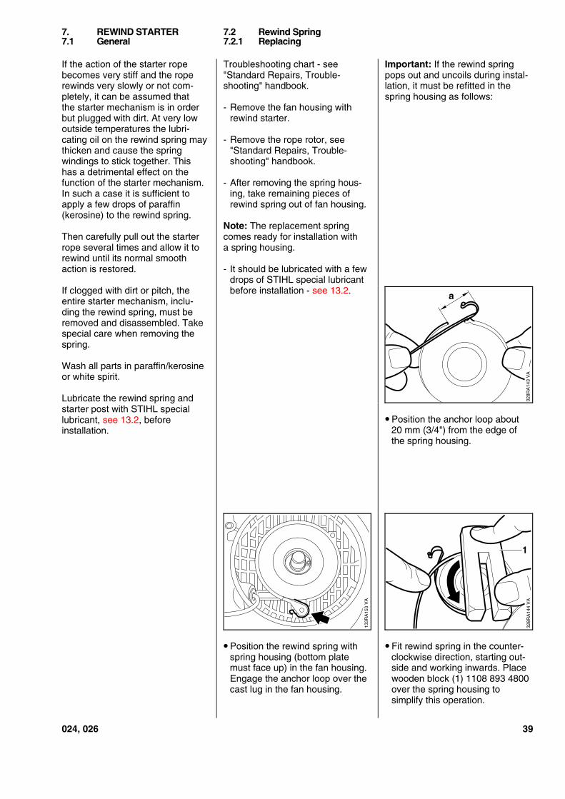
- Remove the air filter - see 12.1.
- Turn switch lever so that itpoints up.
• Pull the ground wire (1) out ofthe contact spring.
• Machines with carburetorheating from serial numberX 33 339 218: Pull flag terminal(2) off the contact spring.
• Pull contact spring out of its seatin the tank housing.
Reassemble in the reversesequence.
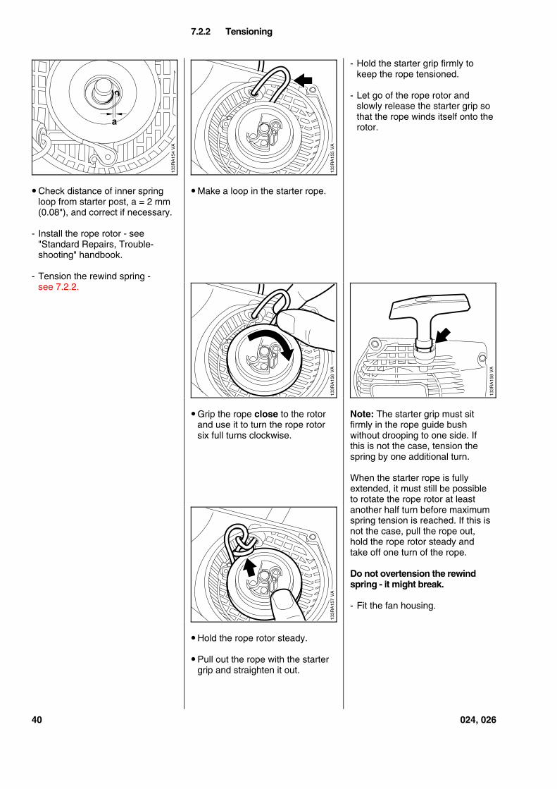
Removing the flywheel
- Use the locking strip to block thepiston - see 4.2.
- Remove the fan housing.
- Rotate the flywheel so that themagnet poles line up with theignition module.
• Unscrew the flywheel mountingnut.
• Use puller (1) 1110 890 4500 torelease the flywheel.
- Pull the flywheel off thecrankshaft.
• The flywheel (1) and magnetpoles (2) must not be cracked ordamaged in any way. Install anew flywheel if necessary.
- For machines with heatedhandles see 10.5.
Installing the flywheel
Important: Clean the stub of thecrankshaft and the flywheel hubbore with a standard commercial,solvent-based degreasant contain-ing no chlorinated or halogenatedhydrocarbons - see 13.2.
• Check that the key is correctlypositioned in the crankshaft.
- Fit the flywheel in position.
- Fit and tighten down flywheel nutto 33 Nm (24.5 lbf.ft).
Assemble all other parts in thereverse sequence.
6.5 Contact Spring 6.6 Flywheel
VA
133R
A14
7
2 1
VA
133R
A15
1
2 1
VA
133R
A14
9
VA
133R
A15
2
VA
133R
A14
8
1
VA
133R
A15
0
38 024, 026
If the action of the starter ropebecomes very stiff and the roperewinds very slowly or not com-pletely, it can be assumed thatthe starter mechanism is in orderbut plugged with dirt. At very lowoutside temperatures the lubri-cating oil on the rewind spring maythicken and cause the springwindings to stick together. Thishas a detrimental effect on thefunction of the starter mechanism.In such a case it is sufficient toapply a few drops of paraffin(kerosine) to the rewind spring.
Then carefully pull out the starterrope several times and allow it torewind until its normal smoothaction is restored.
If clogged with dirt or pitch, theentire starter mechanism, inclu-ding the rewind spring, must beremoved and disassembled. Takespecial care when removing thespring.
Wash all parts in paraffin/kerosineor white spirit.
Lubricate the rewind spring andstarter post with STIHL speciallubricant, see 13.2, beforeinstallation.
Troubleshooting chart - see"Standard Repairs, Trouble-shooting" handbook.
- Remove the fan housing withrewind starter.
- Remove the rope rotor, see"Standard Repairs, Trouble-shooting" handbook.
- After removing the spring hous-ing, take remaining pieces ofrewind spring out of fan housing.
Note: The replacement springcomes ready for installation witha spring housing.
- It should be lubricated with a fewdrops of STIHL special lubricantbefore installation - see 13.2.
• Position the rewind spring withspring housing (bottom platemust face up) in the fan housing.Engage the anchor loop over thecast lug in the fan housing.
Important: If the rewind springpops out and uncoils during instal-lation, it must be refitted in thespring housing as follows:
• Position the anchor loop about20 mm (3/4") from the edge ofthe spring housing.
• Fit rewind spring in the counter-clockwise direction, starting out-side and working inwards. Placewooden block (1) 1108 893 4800over the spring housing tosimplify this operation.
7. REWIND STARTER 7.2 Rewind Spring7.1 General 7.2.1 Replacing
328R
A14
3 V
A
a
VA
133R
A15
3
328R
A14
4 V
A
1
024, 026 39
• Check distance of inner springloop from starter post, a = 2 mm(0.08"), and correct if necessary.
- Install the rope rotor - see"Standard Repairs, Trouble-shooting" handbook.
- Tension the rewind spring -see 7.2.2.
• Make a loop in the starter rope.
• Grip the rope close to the rotorand use it to turn the rope rotorsix full turns clockwise.
• Hold the rope rotor steady.
• Pull out the rope with the startergrip and straighten it out.
- Hold the starter grip firmly tokeep the rope tensioned.
- Let go of the rope rotor andslowly release the starter grip sothat the rope winds itself onto therotor.
Note: The starter grip must sitfirmly in the rope guide bushwithout drooping to one side. Ifthis is not the case, tension thespring by one additional turn.
When the starter rope is fullyextended, it must still be possibleto rotate the rope rotor at leastanother half turn before maximumspring tension is reached. If this isnot the case, pull the rope out,hold the rope rotor steady andtake off one turn of the rope.
Do not overtension the rewindspring - it might break.
- Fit the fan housing.
7.2.2 Tensioning
VA
133R
A15
4
a
VA
133R
A15
5V
A13
3RA
156
VA
133R
A15
8
VA
133R
A15
7
40 024, 026
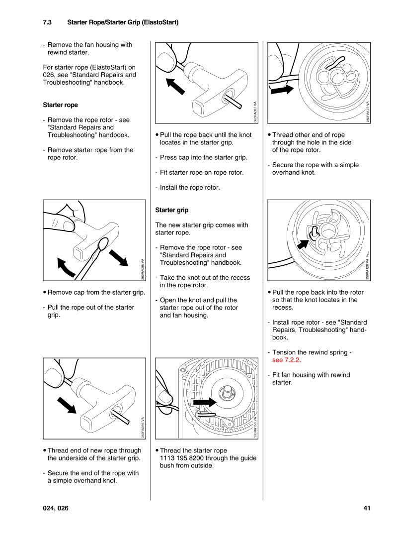
- Remove the fan housing withrewind starter.
For starter rope (ElastoStart) on026, see "Standard Repairs andTroubleshooting" handbook.
Starter rope
- Remove the rope rotor - see"Standard Repairs andTroubleshooting" handbook.
- Remove starter rope from therope rotor.
• Remove cap from the starter grip.
- Pull the rope out of the startergrip.
• Thread end of new rope throughthe underside of the starter grip.
- Secure the end of the rope witha simple overhand knot.
• Pull the rope back until the knotlocates in the starter grip.
- Press cap into the starter grip.
- Fit starter rope on rope rotor.
- Install the rope rotor.
Starter grip
The new starter grip comes withstarter rope.
- Remove the rope rotor - see"Standard Repairs andTroubleshooting" handbook.
- Take the knot out of the recessin the rope rotor.
- Open the knot and pull thestarter rope out of the rotorand fan housing.
• Thread the starter rope1113 195 8200 through the guidebush from outside.
• Thread other end of ropethrough the hole in the sideof the rope rotor.
- Secure the rope with a simpleoverhand knot.
• Pull the rope back into the rotorso that the knot locates in therecess.
- Install rope rotor - see "StandardRepairs, Troubleshooting" hand-book.
- Tension the rewind spring -see 7.2.2.
- Fit fan housing with rewindstarter.
7.3 Starter Rope/Starter Grip (ElastoStart)
VA
362R
A09
7
VA
250R
A12
7
VA
362R
A09
5
VA
250R
A12
8
VA
133R
A15
9
VA
362R
A09
6
024, 026 41
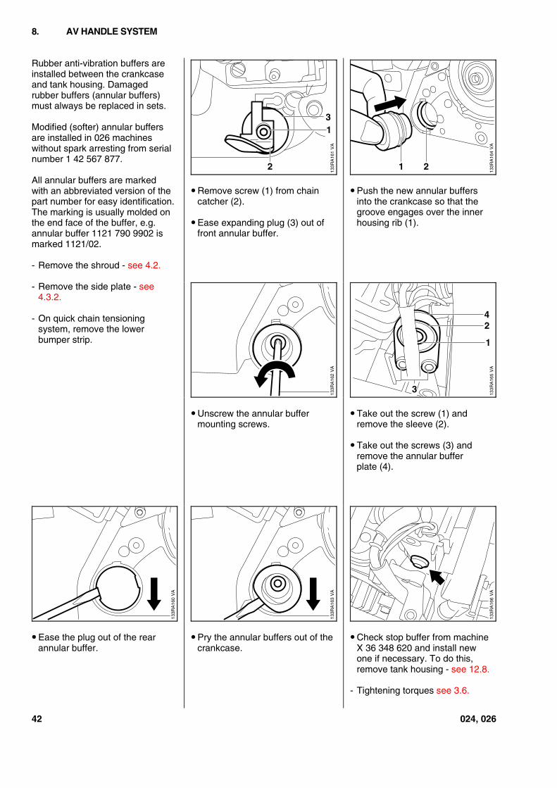
Rubber anti-vibration buffers areinstalled between the crankcaseand tank housing. Damagedrubber buffers (annular buffers)must always be replaced in sets.
Modified (softer) annular buffersare installed in 026 machineswithout spark arresting from serialnumber 1 42 567 877.
All annular buffers are markedwith an abbreviated version of thepart number for easy identification.The marking is usually molded onthe end face of the buffer, e.g.annular buffer 1121 790 9902 ismarked 1121/02.
- Remove the shroud - see 4.2.
- Remove the side plate - see4.3.2.
- On quick chain tensioningsystem, remove the lowerbumper strip.
• Ease the plug out of the rearannular buffer.
• Remove screw (1) from chaincatcher (2).
• Ease expanding plug (3) out offront annular buffer.
• Unscrew the annular buffermounting screws.
• Pry the annular buffers out of thecrankcase.
• Push the new annular buffersinto the crankcase so that thegroove engages over the innerhousing rib (1).
• Take out the screw (1) andremove the sleeve (2).
• Take out the screws (3) andremove the annular bufferplate (4).
• Check stop buffer from machineX 36 348 620 and install newone if necessary. To do this,remove tank housing - see 12.8.
- Tightening torques see 3.6.
8. AV HANDLE SYSTEM
VA
133R
A16
1
2
31
VA
133R
A16
4
21
VA
133R
A16
2
VA
133R
A16
5
42
3
1
VA
133R
A16
0
VA
133R
A16
3
VA
133R
A16
6
42 024, 026
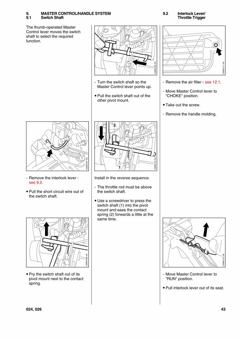
The thumb-operated MasterControl lever moves the switchshaft to select the requiredfunction.
- Remove the interlock lever -see 9.2.
• Pull the short circuit wire out ofthe switch shaft.
• Pry the switch shaft out of itspivot mount next to the contactspring.
- Turn the switch shaft so theMaster Control lever points up.
• Pull the switch shaft out of theother pivot mount.
Install in the reverse sequence.
- The throttle rod must be abovethe switch shaft.
• Use a screwdriver to press theswitch shaft (1) into the pivotmount and ease the contactspring (2) forwards a little at thesame time.
- Remove the air filter - see 12.1.
- Move Master Control lever to"CHOKE" position.
• Take out the screw.
- Remove the handle molding.
- Move Master Control lever to"RUN" position.
• Pull interlock lever out of its seat.
9. MASTER CONTROL/HANDLE SYSTEM 9.2 Interlock Lever/9.1 Switch Shaft Throttle Trigger
VA
133R
A16
9
VA
133R
A17
1
VA
133R
A16
7
VA
133R
A17
0
2
1
VA
133R
A16
8
VA
133R
A17
2
024, 026 43
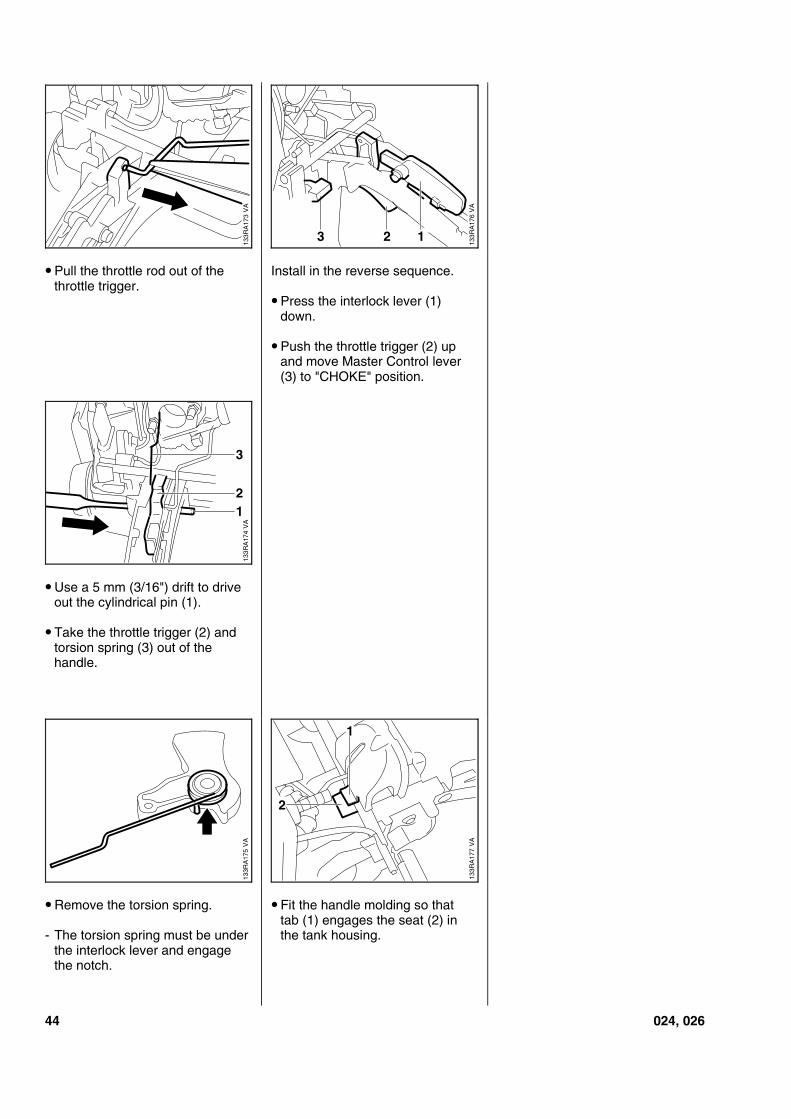
• Pull the throttle rod out of thethrottle trigger.
• Use a 5 mm (3/16") drift to driveout the cylindrical pin (1).
• Take the throttle trigger (2) andtorsion spring (3) out of thehandle.
• Remove the torsion spring.
- The torsion spring must be underthe interlock lever and engagethe notch.
Install in the reverse sequence.
• Press the interlock lever (1)down.
• Push the throttle trigger (2) upand move Master Control lever(3) to "CHOKE" position.
• Fit the handle molding so thattab (1) engages the seat (2) inthe tank housing.
VA
133R
A17
3
VA
133R
A17
6
3 2 1
VA
133R
A17
7
2
1
VA
133R
A17
5V
A13
3RA
174
21
3
44 024, 026
The entire handle heating systemis maintenance-free and subject topractically no wear. Faults in thegenerator, heating elements andwiring are generally caused bymechanical damage.
Heating elements with a higherresistance are installed from serialnumber X 33 339 218 - see 10.3or 10.4.
There are two reasons for failuresin the heating system:
1. A break in the circuit due to afaulty wire or component.
2. A short circuit resulting fromdamaged insulation.
Important: The heating element inthe rear handle may overheat and
fail if it is not bonded firmly inposition, i.e. completely flat (nocreases).
To trace the cause of a fault:
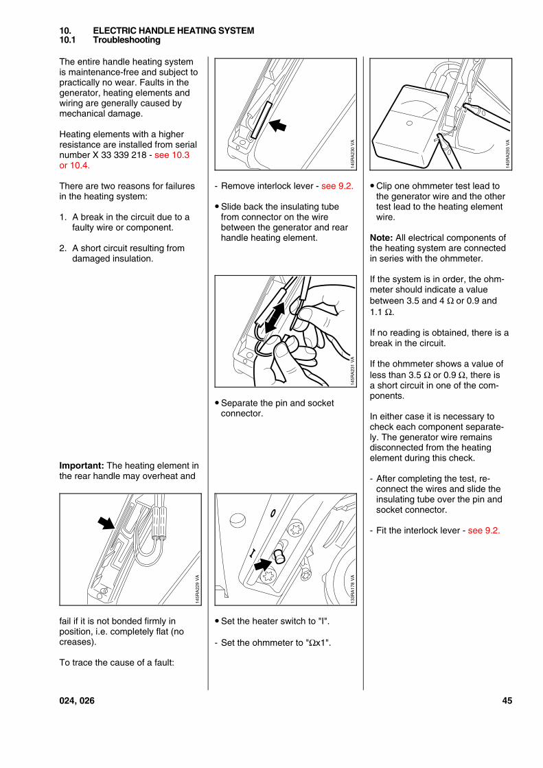
- Remove interlock lever - see 9.2.
• Slide back the insulating tubefrom connector on the wirebetween the generator and rearhandle heating element.
• Separate the pin and socketconnector.
• Set the heater switch to "I".
- Set the ohmmeter to "Ωx1".
• Clip one ohmmeter test lead tothe generator wire and the othertest lead to the heating elementwire.
Note: All electrical components ofthe heating system are connectedin series with the ohmmeter.
If the system is in order, the ohm-meter should indicate a valuebetween 3.5 and 4 Ω=or 0.9 and1.1 Ω.
If no reading is obtained, there is abreak in the circuit.
If the ohmmeter shows a value ofless than 3.5 Ω=or 0.9=Ω, there isa short circuit in one of the com-ponents.
In either case it is necessary tocheck each component separate-ly. The generator wire remainsdisconnected from the heatingelement during this check.
- After completing the test, re-connect the wires and slide theinsulating tube over the pin andsocket connector.
- Fit the interlock lever - see 9.2.
10. ELECTRIC HANDLE HEATING SYSTEM10.1 Troubleshooting
VA
145R
A23
0
VA
145R
A22
9
VA
145R
A29
3
VA
145R
A23
1V
A13
3RA
178
024, 026 45
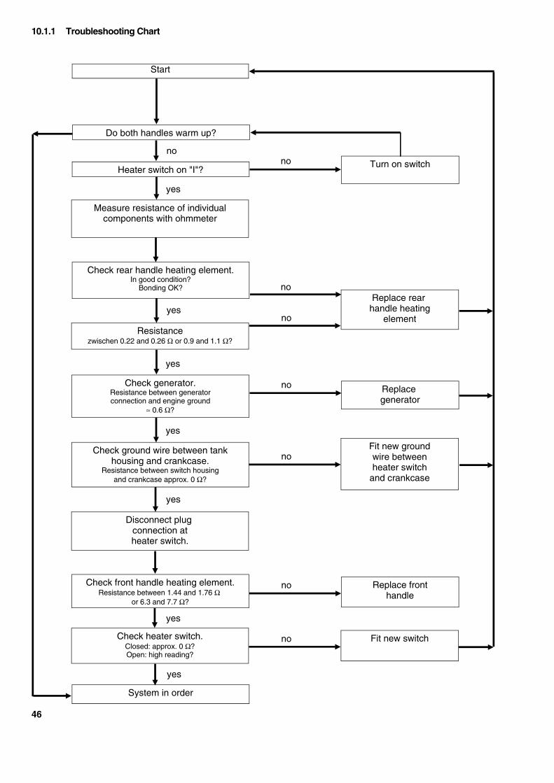
Resistancezwischen 0.22 and 0.26 Ω or 0.9 and 1.1 Ω?
Start
Do both handles warm up?
Replacegenerator
Heater switch on "I"?
Measure resistance of individualcomponents with ohmmeter
Turn on switch
System in order
Check rear handle heating element.In good condition?
Bonding OK?
Check generator.Resistance between generatorconnection and engine ground
≈ 0.6 Ω?
Fit new switch
Replace rearhandle heating
element
Check ground wire between tankhousing and crankcase.
Resistance between switch housingand crankcase approx. 0 Ω?
Check heater switch.Closed: approx. 0 Ω?Open: high reading?
Disconnect plugconnection atheater switch.
Check front handle heating element.Resistance between 1.44 and 1.76 Ω
or 6.3 and 7.7 Ω?
Fit new groundwire betweenheater switch
and crankcase
Replace fronthandle
no
no
no
no
no
no
no
no
yes
yes
yes
yes
yes
yes
yes
10.1.1 Troubleshooting Chart
46
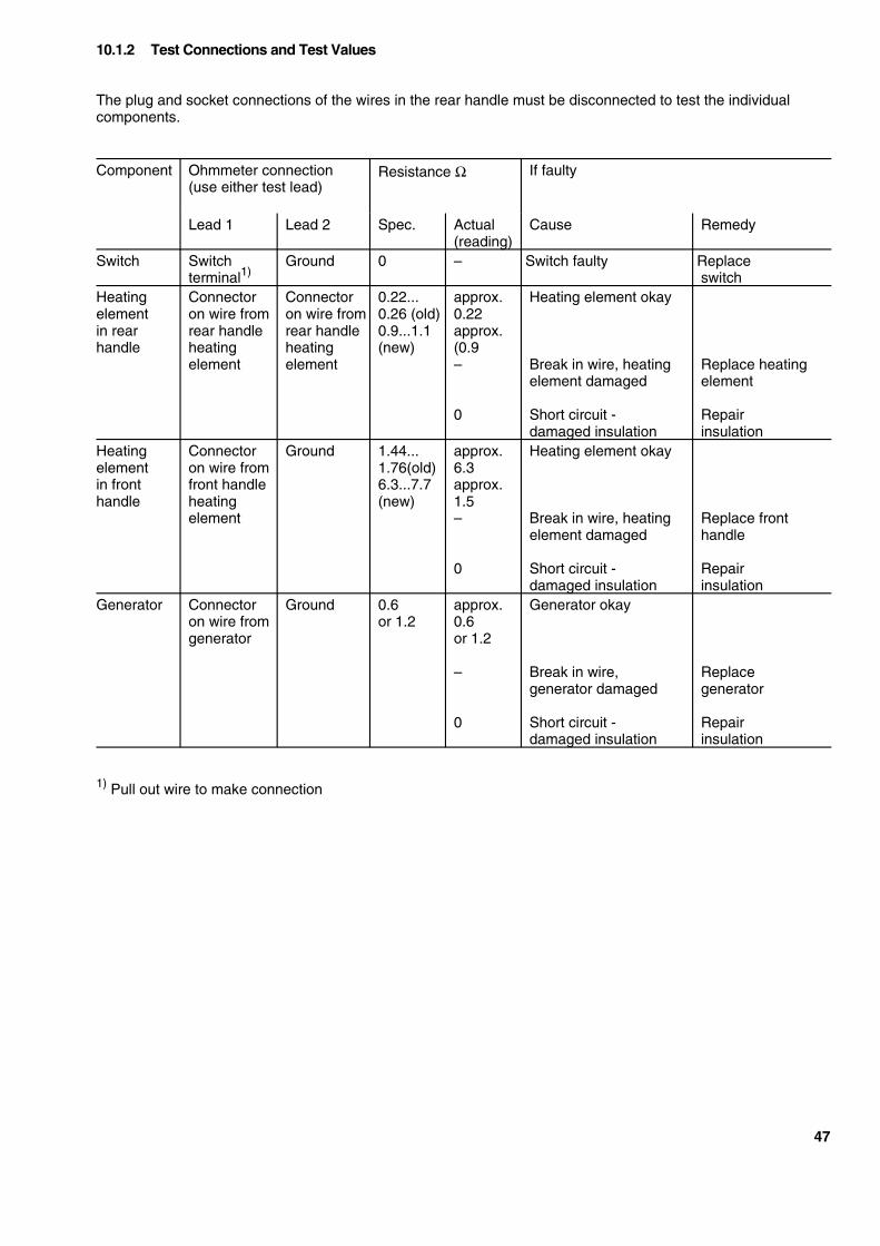
The plug and socket connections of the wires in the rear handle must be disconnected to test the individualcomponents.
Component Ohmmeter connection(use either test lead)
Resistance Ω If faulty
Lead 1 Lead 2 Spec. Actual(reading)
Cause Remedy
Switch Switchterminal1)
Ground 0 – Switch faulty Replaceswitch
Heatingelementin rearhandle
Connectoron wire fromrear handleheatingelement
Connectoron wire fromrear handleheatingelement
0.22...0.26 (old)0.9...1.1(new)
approx.0.22approx.(0.9–
0
Heating element okay
Break in wire, heatingelement damaged
Short circuit -damaged insulation
Replace heatingelement
Repairinsulation
Heatingelementin fronthandle
Connectoron wire fromfront handleheatingelement
Ground 1.44...1.76(old)6.3...7.7(new)
approx.6.3approx.1.5–
0
Heating element okay
Break in wire, heatingelement damaged
Short circuit -damaged insulation
Replace fronthandle
Repairinsulation
Generator Connectoron wire fromgenerator
Ground 0.6or 1.2
approx.0.6or 1.2
–
0
Generator okay
Break in wire,generator damaged
Short circuit -damaged insulation
Replacegenerator
Repairinsulation
1) Pull out wire to make connection
10.1.2 Test Connections and Test Values
47
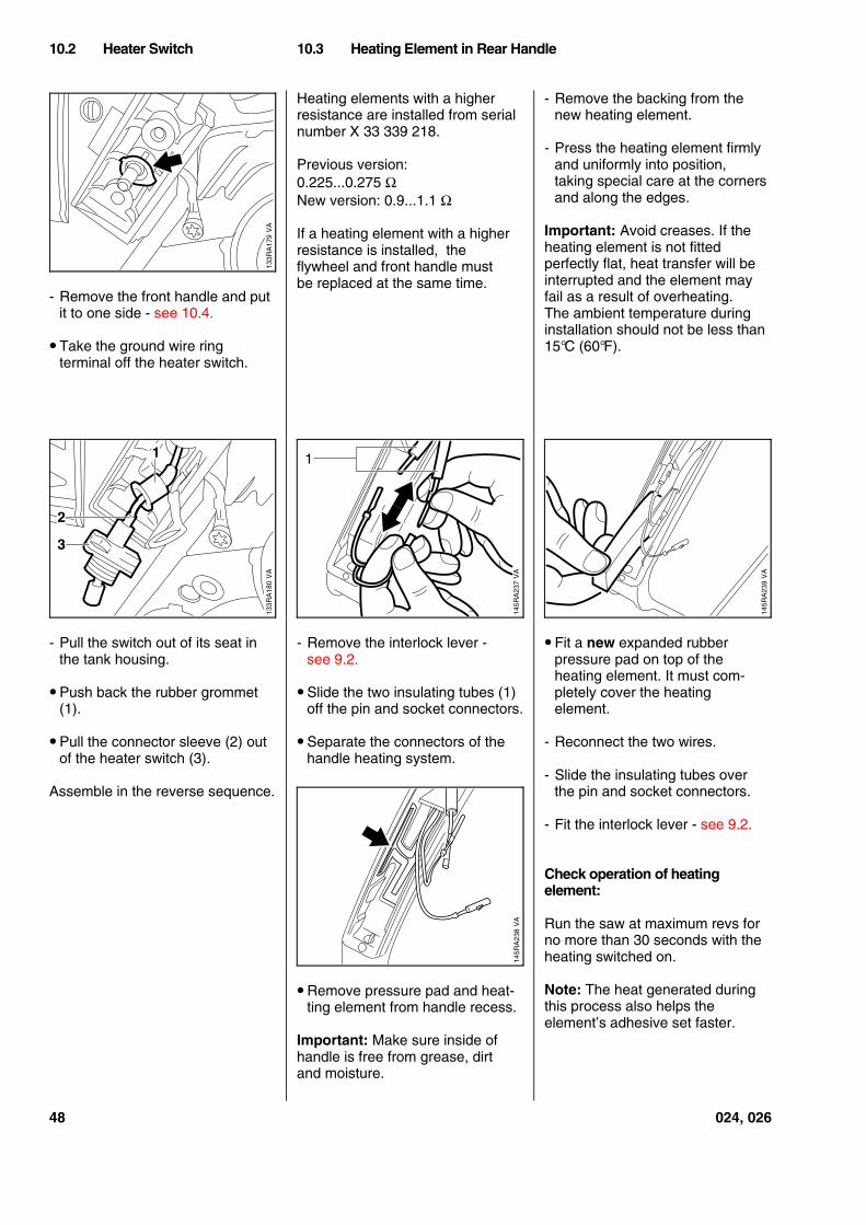
- Remove the front handle and putit to one side - see 10.4.
• Take the ground wire ringterminal off the heater switch.
- Pull the switch out of its seat inthe tank housing.
• Push back the rubber grommet(1).
• Pull the connector sleeve (2) outof the heater switch (3).
Assemble in the reverse sequence.
Heating elements with a higherresistance are installed from serialnumber X 33 339 218.
Previous version:0.225...0.275 ΩNew version: 0.9...1.1 Ω
If a heating element with a higherresistance is installed, theflywheel and front handle mustbe replaced at the same time.
- Remove the interlock lever -see 9.2.
• Slide the two insulating tubes (1)off the pin and socket connectors.
• Separate the connectors of thehandle heating system.
• Remove pressure pad and heat-ting element from handle recess.
Important: Make sure inside ofhandle is free from grease, dirtand moisture.
- Remove the backing from thenew heating element.
- Press the heating element firmlyand uniformly into position,taking special care at the cornersand along the edges.
Important: Avoid creases. If theheating element is not fittedperfectly flat, heat transfer will beinterrupted and the element mayfail as a result of overheating.The ambient temperature duringinstallation should not be less than15°C (60°F).
• Fit a new expanded rubberpressure pad on top of theheating element. It must com-pletely cover the heatingelement.
- Reconnect the two wires.
- Slide the insulating tubes overthe pin and socket connectors.
- Fit the interlock lever - see 9.2.
Check operation of heatingelement:
Run the saw at maximum revs forno more than 30 seconds with theheating switched on.
Note: The heat generated duringthis process also helps theelement’s adhesive set faster.
10.2 Heater Switch 10.3 Heating Element in Rear Handle
VA
133R
A17
9V
A13
3RA
180
2
1
3
VA
145R
A23
9
VA
145R
A23
8V
A14
5RA
237
1
48 024, 026
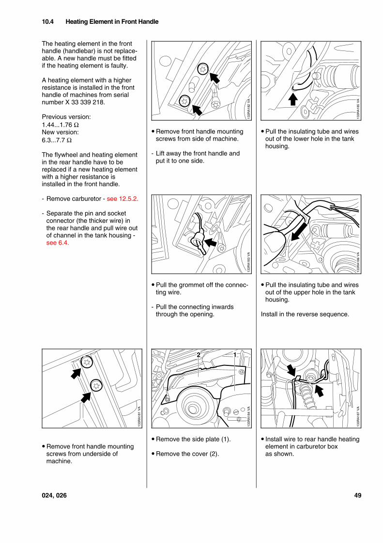
The heating element in the fronthandle (handlebar) is not replace-able. A new handle must be fittedif the heating element is faulty.
A heating element with a higherresistance is installed in the fronthandle of machines from serialnumber X 33 339 218.
Previous version:1.44...1.76 ΩNew version:6.3...7.7 Ω
The flywheel and heating elementin the rear handle have to bereplaced if a new heating elementwith a higher resistance isinstalled in the front handle.
- Remove carburetor - see 12.5.2.
- Separate the pin and socketconnector (the thicker wire) inthe rear handle and pull wire outof channel in the tank housing -see 6.4.
• Remove front handle mountingscrews from underside ofmachine.
• Remove front handle mountingscrews from side of machine.
- Lift away the front handle andput it to one side.
• Pull the grommet off the connec-ting wire.
- Pull the connecting inwardsthrough the opening.
• Remove the side plate (1).
• Remove the cover (2).
• Pull the insulating tube and wiresout of the lower hole in the tankhousing.
• Pull the insulating tube and wiresout of the upper hole in the tankhousing.
Install in the reverse sequence.
• Install wire to rear handle heatingelement in carburetor boxas shown.
10.4 Heating Element in Front Handle
VA
133R
A18
2
VA
133R
A18
5
VA
133R
A18
3
133R
A18
6V
A
VA
133R
A18
1
VA
133R
A18
4
2 1V
A13
3RA
187
024, 026 49
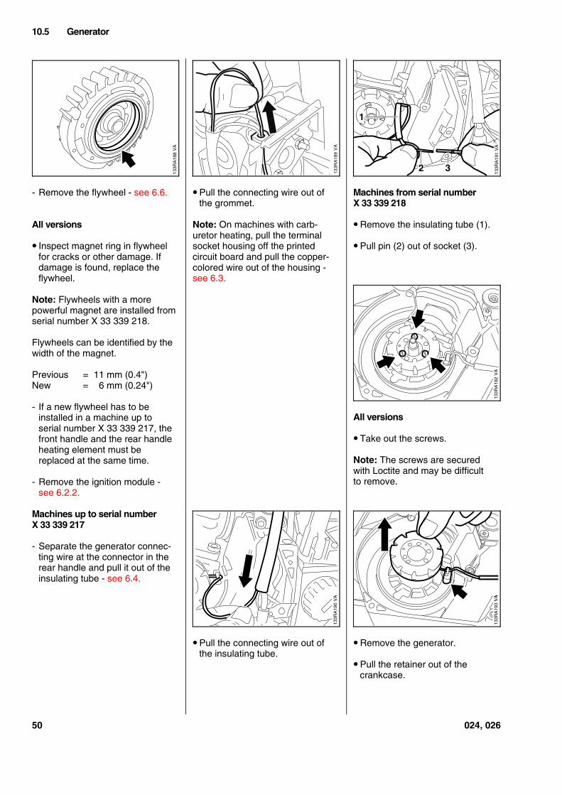
- Remove the flywheel - see 6.6.
All versions
• Inspect magnet ring in flywheelfor cracks or other damage. Ifdamage is found, replace theflywheel.
Note: Flywheels with a morepowerful magnet are installed fromserial number X 33 339 218.
Flywheels can be identified by thewidth of the magnet.
Previous = 11 mm (0.4")New = 6 mm (0.24")
- If a new flywheel has to beinstalled in a machine up toserial number X 33 339 217, thefront handle and the rear handleheating element must bereplaced at the same time.
- Remove the ignition module -see 6.2.2.
Machines up to serial numberX 33 339 217
- Separate the generator connec-ting wire at the connector in therear handle and pull it out of theinsulating tube - see 6.4.
• Pull the connecting wire out ofthe grommet.
Note: On machines with carb-uretor heating, pull the terminalsocket housing off the printedcircuit board and pull the copper-colored wire out of the housing -see 6.3.
• Pull the connecting wire out ofthe insulating tube.
Machines from serial numberX 33 339 218
• Remove the insulating tube (1).
• Pull pin (2) out of socket (3).
All versions
• Take out the screws.
Note: The screws are securedwith Loctite and may be difficultto remove.
• Remove the generator.
• Pull the retainer out of thecrankcase.
10.5 Generator
VA
133R
A18
8
VA
133R
A19
1
1
2 3
VA
133R
A19
2
133R
A19
0V
A
VA
133R
A19
3V
A
50 024, 026
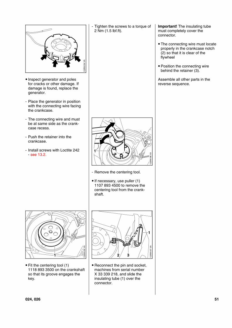
• Inspect generator and polesfor cracks or other damage. Ifdamage is found, replace thegenerator.
- Place the generator in positionwith the connecting wire facingthe crankcase.
- The connecting wire and mustbe at same side as the crank-case recess.
- Push the retainer into thecrankcase.
- Install screws with Loctite 242- see 13.2.
• Fit the centering tool (1)1118 893 3500 on the crankshaftso that its groove engages thekey.
- Tighten the screws to a torque of2 Nm (1.5 lbf.ft).
- Remove the centering tool.
• If necessary, use puller (1)1107 893 4500 to remove thecentering tool from the crank-shaft.
• Reconnect the pin and socket,machines from serial numberX 33 339 218, and slide theinsulating tube (1) over theconnector.
Important! The insulating tubemust completely cover theconnector.
• The connecting wire must locateproperly in the crankcase notch(2) so that it is clear of theflywheel
• Position the connecting wirebehind the retainer (3).
Assemble all other parts in thereverse sequence.
VA
133R
A19
4
VA
133R
A19
61
VA
133R
A19
5
1
VA
133R
A19
7
1
32
024, 026 51
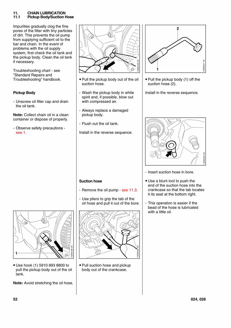
Impurities gradually clog the finepores of the filter with tiny particlesof dirt. This prevents the oil pumpfrom supplying sufficient oil to thebar and chain. In the event ofproblems with the oil supplysystem, first check the oil tank andthe pickup body. Clean the oil tankif necessary.
Troubleshooting chart - see"Standard Repairs andTroubleshooting" handbook.
Pickup Body
- Unscrew oil filler cap and drainthe oil tank.
Note: Collect chain oil in a cleancontainer or dispose of properly.
- Observe safety precautions -see 1.
• Use hook (1) 5910 893 8800 topull the pickup body out of the oiltank.
Note: Avoid stretching the oil hose.
• Pull the pickup body out of the oilsuction hose.
- Wash the pickup body in whitespirit and, if possible, blow outwith compressed air.
- Always replace a damagedpickup body.
- Flush out the oil tank.
Install in the reverse sequence.
Suction hose
- Remove the oil pump - see 11.3.
- Use pliers to grip the tab of theoil hose and pull it out of the bore.
• Pull suction hose and pickupbody out of the crankcase.
• Pull the pickup body (1) off thesuction hose (2).
Install in the reverse sequence.
- Insert suction hose in bore.
• Use a blunt tool to push theend of the suction hose into thecrankcase so that the tab locatesit its seat at the bottom right.
- This operation is easier if thebead of the hose is lubricatedwith a little oil.
11. CHAIN LUBRICATION11.1 Pickup Body/Suction Hose
VA
133R
A19
8
1
VA
133R
A20
0V
A13
3RA
199
VA
133R
A20
1
2
1
52 024, 026
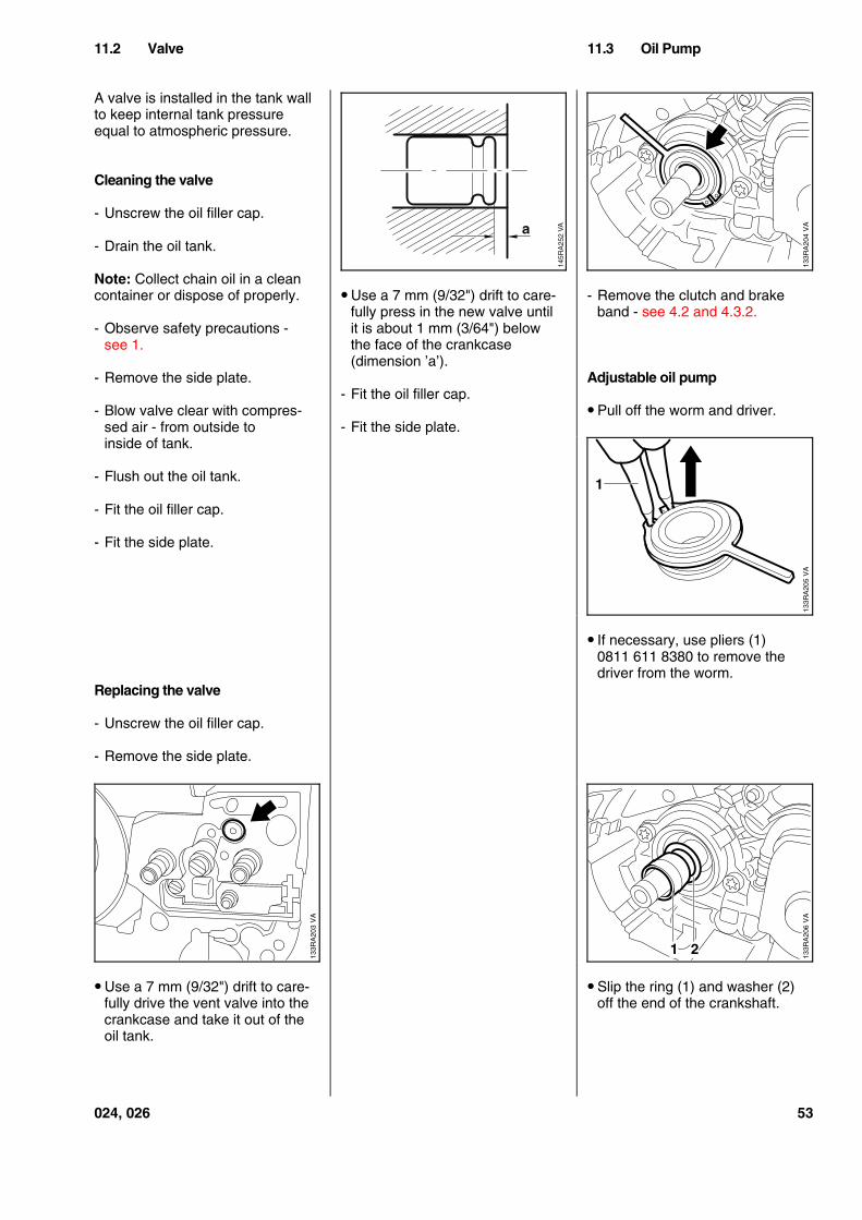
A valve is installed in the tank wallto keep internal tank pressureequal to atmospheric pressure.
Cleaning the valve
- Unscrew the oil filler cap.
- Drain the oil tank.
Note: Collect chain oil in a cleancontainer or dispose of properly.
- Observe safety precautions -see 1.
- Remove the side plate.
- Blow valve clear with compres-sed air - from outside toinside of tank.
- Flush out the oil tank.
- Fit the oil filler cap.
- Fit the side plate.
Replacing the valve
- Unscrew the oil filler cap.
- Remove the side plate.
• Use a 7 mm (9/32") drift to care-fully drive the vent valve into thecrankcase and take it out of theoil tank.
• Use a 7 mm (9/32") drift to care-fully press in the new valve untilit is about 1 mm (3/64") belowthe face of the crankcase(dimension ’a’).
- Fit the oil filler cap.
- Fit the side plate.
- Remove the clutch and brakeband - see 4.2 and 4.3.2.
Adjustable oil pump
• Pull off the worm and driver.
• If necessary, use pliers (1)0811 611 8380 to remove thedriver from the worm.
• Slip the ring (1) and washer (2)off the end of the crankshaft.
11.2 Valve 11.3 Oil Pump
VA
133R
A20
3
VA
145R
A25
2a VA
133R
A20
4V
A13
3RA
205
1
VA
133R
A20
6
1 2
024, 026 53
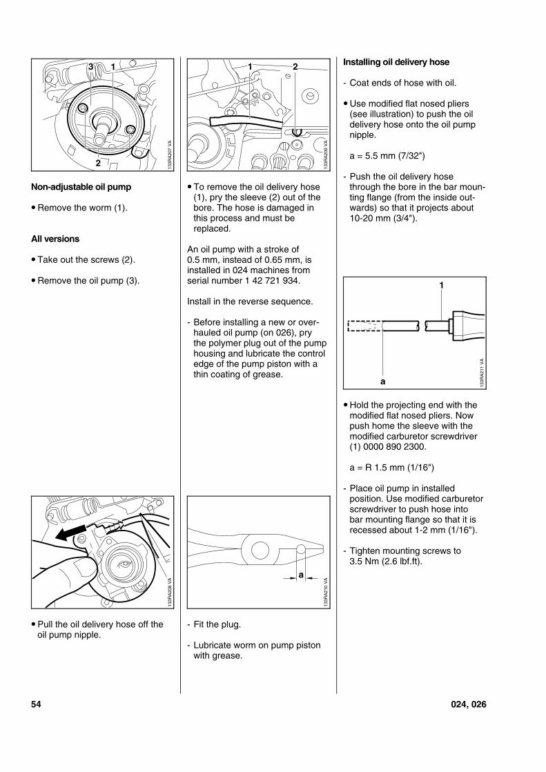
Non-adjustable oil pump
• Remove the worm (1).
All versions
• Take out the screws (2).
• Remove the oil pump (3).
• Pull the oil delivery hose off theoil pump nipple.
• To remove the oil delivery hose(1), pry the sleeve (2) out of thebore. The hose is damaged inthis process and must bereplaced.
An oil pump with a stroke of0.5 mm, instead of 0.65 mm, isinstalled in 024 machines fromserial number 1 42 721 934.
Install in the reverse sequence.
- Before installing a new or over-hauled oil pump (on 026), prythe polymer plug out of the pumphousing and lubricate the controledge of the pump piston with athin coating of grease.
- Fit the plug.
- Lubricate worm on pump pistonwith grease.
Installing oil delivery hose
- Coat ends of hose with oil.
• Use modified flat nosed pliers(see illustration) to push the oildelivery hose onto the oil pumpnipple.
a = 5.5 mm (7/32")
- Push the oil delivery hosethrough the bore in the bar moun-ting flange (from the inside out-wards) so that it projects about10-20 mm (3/4").
• Hold the projecting end with themodified flat nosed pliers. Nowpush home the sleeve with themodified carburetor screwdriver(1) 0000 890 2300.
a = R 1.5 mm (1/16")
- Place oil pump in installedposition. Use modified carburetorscrewdriver to push hose intobar mounting flange so that it isrecessed about 1-2 mm (1/16").
- Tighten mounting screws to3.5 Nm (2.6 lbf.ft).
VA
133R
A20
72
13
VA
133R
A20
9
1 2
VA
133R
A21
1
1
a
VA
133R
A20
8
VA
133R
A21
0
a
54 024, 026
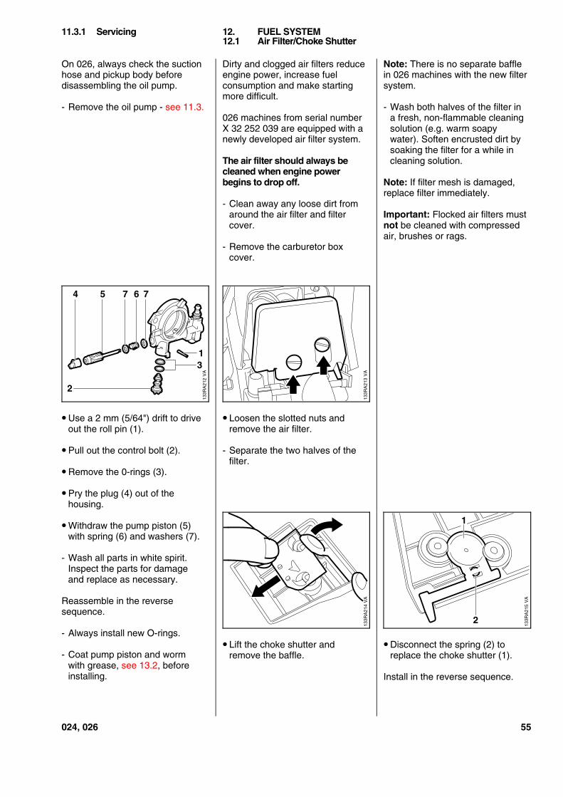
On 026, always check the suctionhose and pickup body beforedisassembling the oil pump.
- Remove the oil pump - see 11.3.
• Use a 2 mm (5/64") drift to driveout the roll pin (1).
• Pull out the control bolt (2).
• Remove the 0-rings (3).
• Pry the plug (4) out of thehousing.
• Withdraw the pump piston (5)with spring (6) and washers (7).
- Wash all parts in white spirit.Inspect the parts for damageand replace as necessary.
Reassemble in the reversesequence.
- Always install new O-rings.
- Coat pump piston and wormwith grease, see 13.2, beforeinstalling.
Dirty and clogged air filters reduceengine power, increase fuelconsumption and make startingmore difficult.
026 machines from serial numberX 32 252 039 are equipped with anewly developed air filter system.
The air filter should always becleaned when engine powerbegins to drop off.
- Clean away any loose dirt fromaround the air filter and filtercover.
- Remove the carburetor boxcover.
• Loosen the slotted nuts andremove the air filter.
- Separate the two halves of thefilter.
• Lift the choke shutter andremove the baffle.
Note: There is no separate bafflein 026 machines with the new filtersystem.
- Wash both halves of the filter ina fresh, non-flammable cleaningsolution (e.g. warm soapywater). Soften encrusted dirt bysoaking the filter for a while incleaning solution.
Note: If filter mesh is damaged,replace filter immediately.
Important: Flocked air filters mustnot be cleaned with compressedair, brushes or rags.
• Disconnect the spring (2) toreplace the choke shutter (1).
Install in the reverse sequence.
11.3.1 Servicing 12. FUEL SYSTEM12.1 Air Filter/Choke Shutter
VA
133R
A21
2
4 5 7 6 7
31
2
VA
133R
A21
3V
A13
3RA
214
2
VA
133R
A21
51
024, 026 55
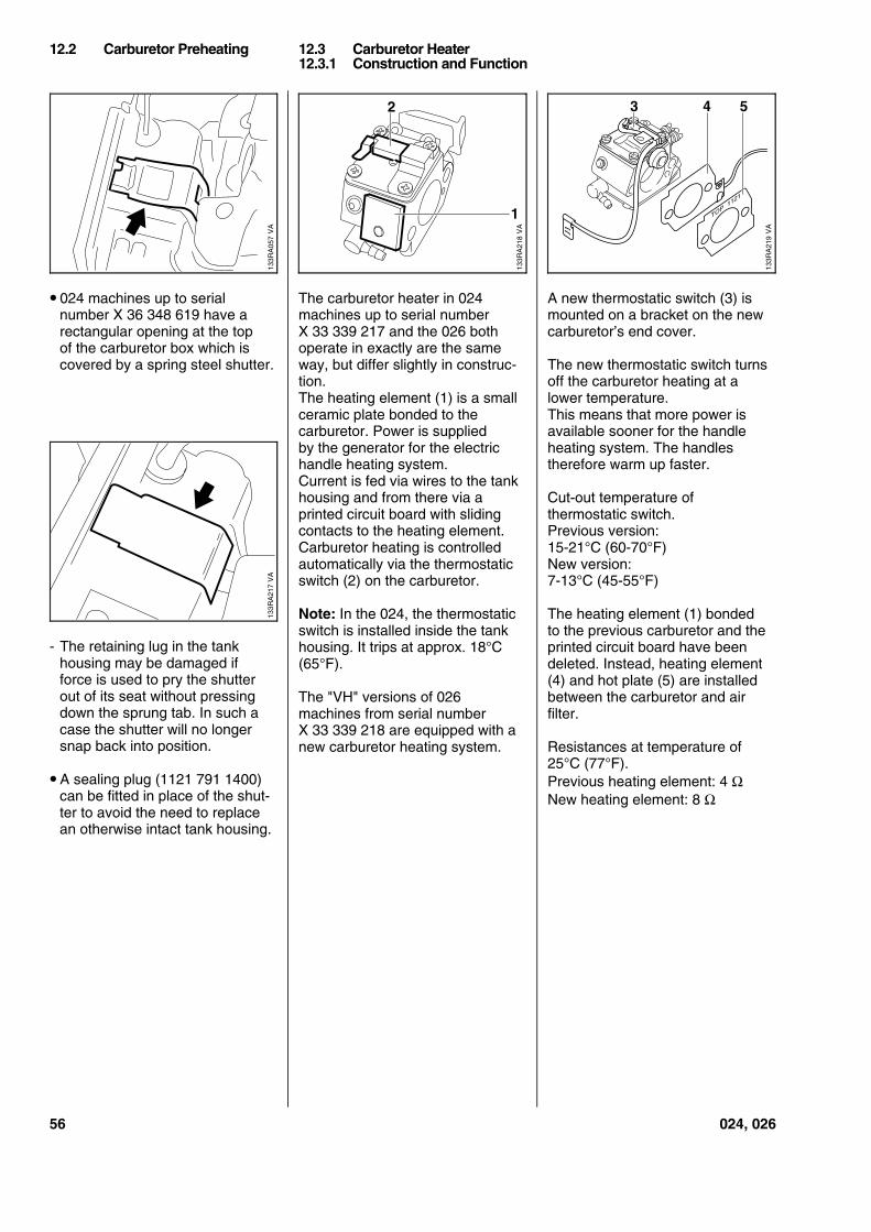
• 024 machines up to serialnumber X 36 348 619 have arectangular opening at the topof the carburetor box which iscovered by a spring steel shutter.
- The retaining lug in the tankhousing may be damaged ifforce is used to pry the shutterout of its seat without pressingdown the sprung tab. In such acase the shutter will no longersnap back into position.
• A sealing plug (1121 791 1400)can be fitted in place of the shut-ter to avoid the need to replacean otherwise intact tank housing.
The carburetor heater in 024machines up to serial numberX 33 339 217 and the 026 bothoperate in exactly are the sameway, but differ slightly in construc-tion.The heating element (1) is a smallceramic plate bonded to thecarburetor. Power is suppliedby the generator for the electrichandle heating system.Current is fed via wires to the tankhousing and from there via aprinted circuit board with slidingcontacts to the heating element.Carburetor heating is controlledautomatically via the thermostaticswitch (2) on the carburetor.
Note: In the 024, the thermostaticswitch is installed inside the tankhousing. It trips at approx. 18°C(65°F).
The "VH" versions of 026machines from serial numberX 33 339 218 are equipped with anew carburetor heating system.
A new thermostatic switch (3) ismounted on a bracket on the newcarburetor’s end cover.
The new thermostatic switch turnsoff the carburetor heating at alower temperature.This means that more power isavailable sooner for the handleheating system. The handlestherefore warm up faster.
Cut-out temperature ofthermostatic switch.Previous version:15-21°C (60-70°F)New version:7-13°C (45-55°F)
The heating element (1) bondedto the previous carburetor and theprinted circuit board have beendeleted. Instead, heating element(4) and hot plate (5) are installedbetween the carburetor and airfilter.
Resistances at temperature of25°C (77°F).Previous heating element: 4 ΩNew heating element: 8 Ω
12.2 Carburetor Preheating 12.3 Carburetor Heater12.3.1 Construction and Function
133R
A05
7V
A
VA
133R
A21
8
2
1
VA
133R
A21
9
3 4 5
TOP 1121
VA
133R
A21
7
56 024, 026
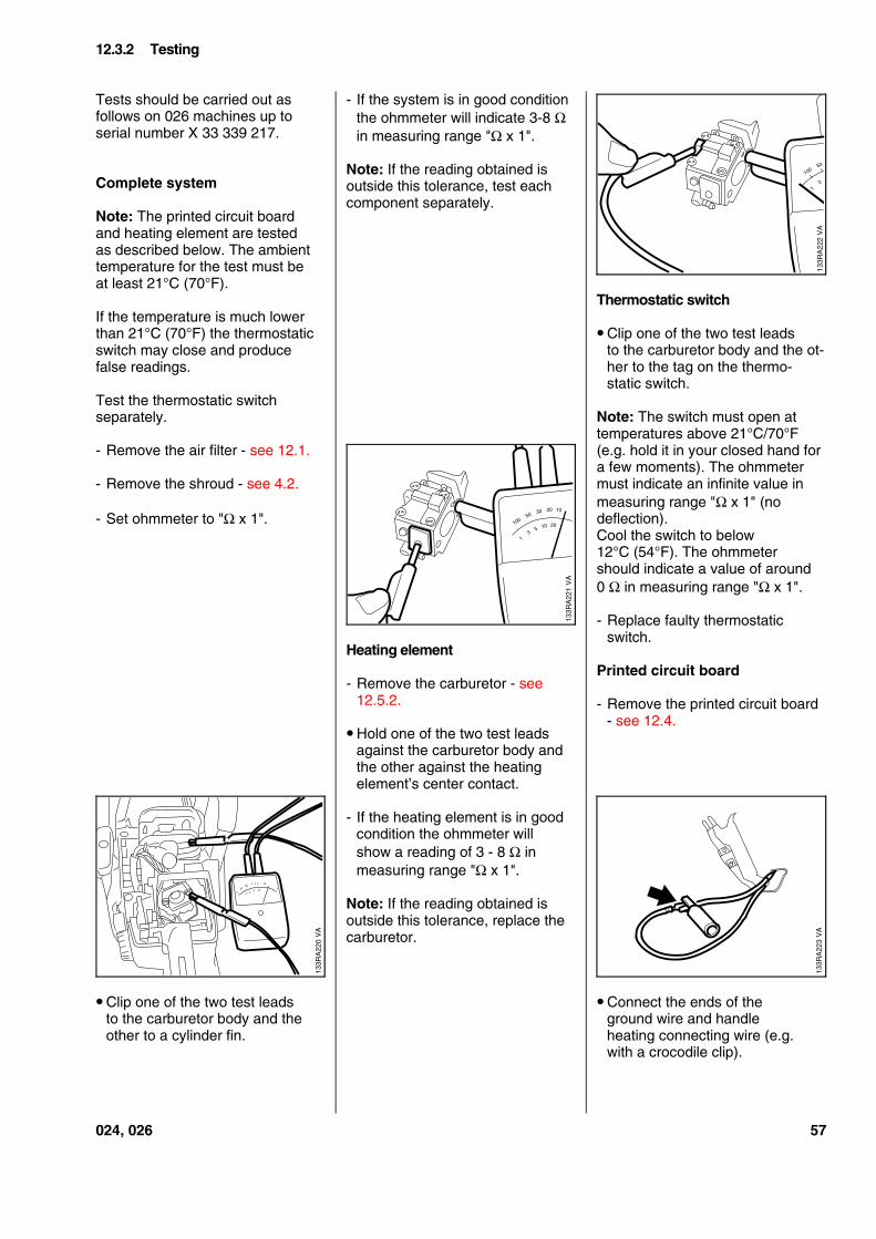
Tests should be carried out asfollows on 026 machines up toserial number X 33 339 217.
Complete system
Note: The printed circuit boardand heating element are testedas described below. The ambienttemperature for the test must beat least 21°C (70°F).
If the temperature is much lowerthan 21°C (70°F) the thermostaticswitch may close and producefalse readings.
Test the thermostatic switchseparately.
- Remove the air filter - see 12.1.
- Remove the shroud - see 4.2.
- Set ohmmeter to "Ω x 1".
• Clip one of the two test leadsto the carburetor body and theother to a cylinder fin.
- If the system is in good conditionthe ohmmeter will indicate 3-8 Ωin measuring range "Ω x 1".
Note: If the reading obtained isoutside this tolerance, test eachcomponent separately.
Heating element
- Remove the carburetor - see12.5.2.
• Hold one of the two test leadsagainst the carburetor body andthe other against the heatingelement’s center contact.
- If the heating element is in goodcondition the ohmmeter willshow a reading of 3 - 8 Ω inmeasuring range "Ω x 1".
Note: If the reading obtained isoutside this tolerance, replace thecarburetor.
Thermostatic switch
• Clip one of the two test leadsto the carburetor body and the ot-her to the tag on the thermo-static switch.
Note: The switch must open attemperatures above 21°C/70°F(e.g. hold it in your closed hand fora few moments). The ohmmetermust indicate an infinite value inmeasuring range "Ω x 1" (nodeflection).Cool the switch to below12°C (54°F). The ohmmetershould indicate a value of around0 Ω in measuring range "Ω x 1".
- Replace faulty thermostaticswitch.
Printed circuit board
- Remove the printed circuit board- see 12.4.
• Connect the ends of theground wire and handleheating connecting wire (e.g.with a crocodile clip).
12.3.2 Testing
VA
133R
A22
2
10050
31
VA
133R
A22
1
10050
31
30 20 10
5 10 20
VA
133R
A22
0
VA
133R
A22
3
024, 026 57
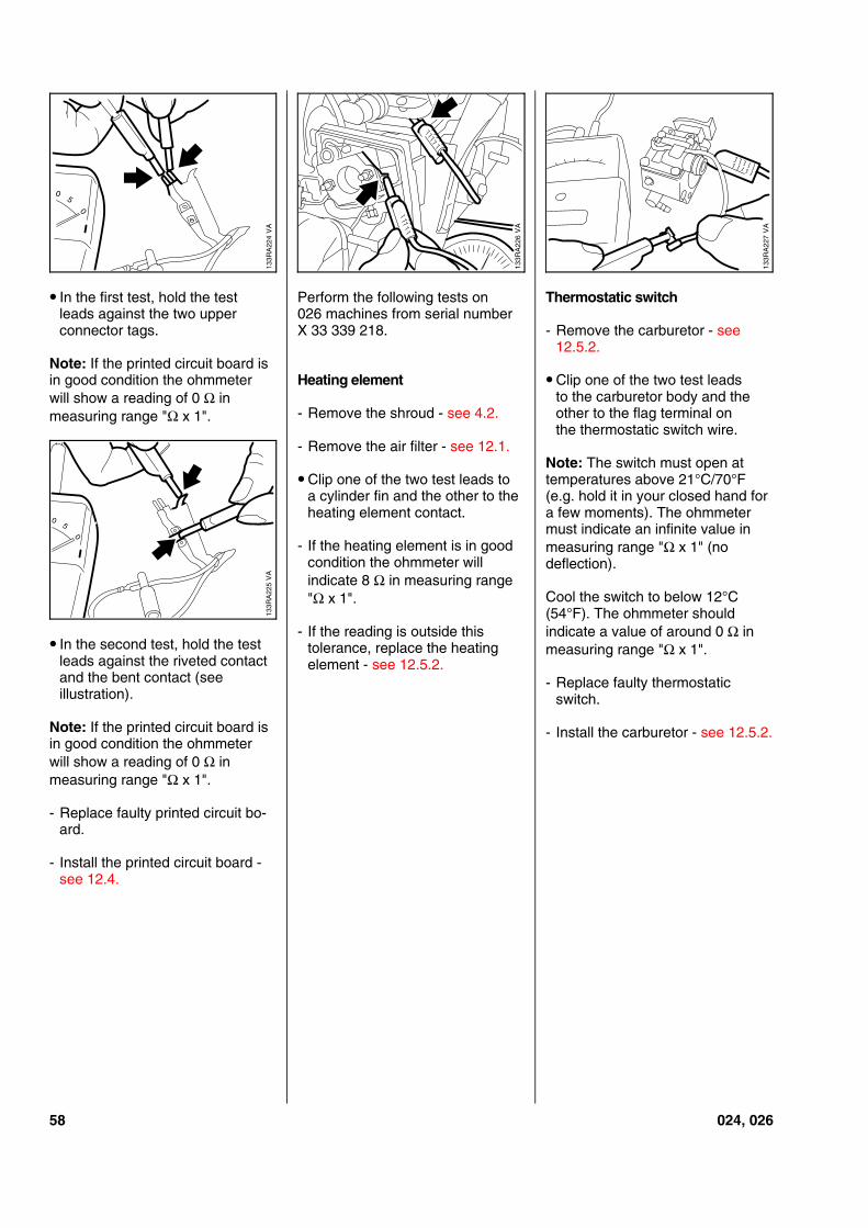
• In the first test, hold the testleads against the two upperconnector tags.
Note: If the printed circuit board isin good condition the ohmmeterwill show a reading of 0 Ω inmeasuring range "Ω x 1".
• In the second test, hold the testleads against the riveted contactand the bent contact (seeillustration).
Note: If the printed circuit board isin good condition the ohmmeterwill show a reading of 0 Ω inmeasuring range "Ω x 1".
- Replace faulty printed circuit bo-ard.
- Install the printed circuit board -see 12.4.
Perform the following tests on026 machines from serial numberX 33 339 218.
Heating element
- Remove the shroud - see 4.2.
- Remove the air filter - see 12.1.
• Clip one of the two test leads toa cylinder fin and the other to theheating element contact.
- If the heating element is in goodcondition the ohmmeter willindicate 8 Ω in measuring range"Ω x 1".
- If the reading is outside thistolerance, replace the heatingelement - see 12.5.2.
Thermostatic switch
- Remove the carburetor - see12.5.2.
• Clip one of the two test leadsto the carburetor body and theother to the flag terminal onthe thermostatic switch wire.
Note: The switch must open attemperatures above 21°C/70°F(e.g. hold it in your closed hand fora few moments). The ohmmetermust indicate an infinite value inmeasuring range "Ω x 1" (nodeflection).
Cool the switch to below 12°C(54°F). The ohmmeter shouldindicate a value of around 0 Ω inmeasuring range "Ω x 1".
- Replace faulty thermostaticswitch.
- Install the carburetor - see 12.5.2.
VA
133R
A22
4
05
133R
A22
6V
A
VA
133R
A22
7
VA
133R
A22
5
05
58 024, 026
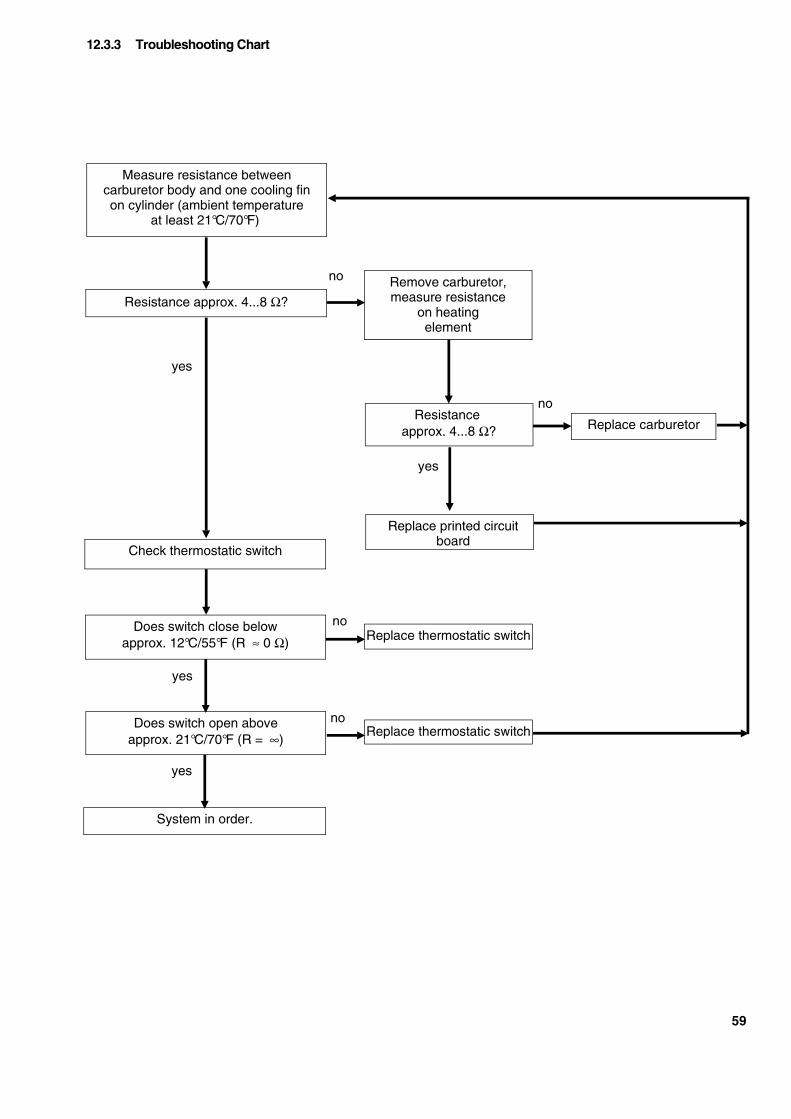
Resistance approx. 4...8 Ω?
Replace printed circuitboard
Measure resistance betweencarburetor body and one cooling finon cylinder (ambient temperature
at least 21°C/70°F)
Remove carburetor,measure resistance
on heatingelement
System in order.
Does switch close belowapprox. 12°C/55°F (R ≈ 0 Ω)
Resistanceapprox. 4...8 Ω?
Does switch open aboveapprox. 21°C/70°F (R = ∞)
Replace carburetor
Replace thermostatic switch
no
no
no
yes
yes
yes
Check thermostatic switch
Replace thermostatic switch
no
yes
12.3.3 Troubleshooting Chart
59
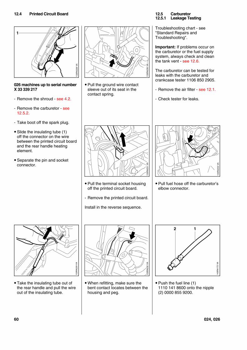
026 machines up to serial numberX 33 339 217
- Remove the shroud - see 4.2.
- Remove the carburetor - see12.5.2.
- Take boot off the spark plug.
• Slide the insulating tube (1)off the connector on the wirebetween the printed circuit boardand the rear handle heatingelement.
• Separate the pin and socketconnector.
• Take the insulating tube out ofthe rear handle and pull the wireout of the insulating tube.
• Pull the ground wire contactsleeve out of its seat in thecontact spring.
• Pull the terminal socket housingoff the printed circuit board.
- Remove the printed circuit board.
Install in the reverse sequence.
• When refitting, make sure thebent contact locates between thehousing and peg.
Troubleshooting chart - see"Standard Repairs andTroubleshooting".
Important: If problems occur onthe carburetor or the fuel supplysystem, always check and cleanthe tank vent - see 12.6.
The carburetor can be tested forleaks with the carburetor andcrankcase tester 1106 850 2905.
- Remove the air filter - see 12.1.
- Check tester for leaks.
• Pull fuel hose off the carburetor’selbow connector.
• Push the fuel line (1)1110 141 8600 onto the nipple(2) 0000 855 9200.
12.4 Printed Circuit Board 12.5 Carburetor12.5.1 Leakage Testing
VA
133R
A22
8
1
VA
133R
A22
9
VA
133R
A23
0V
A13
3RA
231
VA
133R
A23
3
VA
133R
A23
2
143R
A17
2
2 1
VA
60 024, 026
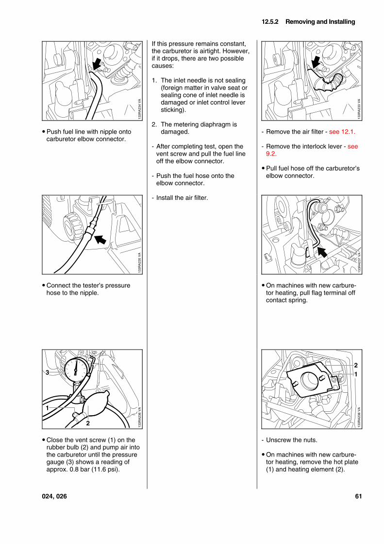
• Push fuel line with nipple ontocarburetor elbow connector.
• Connect the tester’s pressurehose to the nipple.
• Close the vent screw (1) on therubber bulb (2) and pump air intothe carburetor until the pressuregauge (3) shows a reading ofapprox. 0.8 bar (11.6 psi).
If this pressure remains constant,the carburetor is airtight. However,if it drops, there are two possiblecauses:
1. The inlet needle is not sealing(foreign matter in valve seat orsealing cone of inlet needle isdamaged or inlet control leversticking).
2. The metering diaphragm isdamaged.
- After completing test, open thevent screw and pull the fuel lineoff the elbow connector.
- Push the fuel hose onto theelbow connector.
- Install the air filter.
- Remove the air filter - see 12.1.
- Remove the interlock lever - see9.2.
• Pull fuel hose off the carburetor’selbow connector.
• On machines with new carbure-tor heating, pull flag terminal offcontact spring.
- Unscrew the nuts.
• On machines with new carbure-tor heating, remove the hot plate(1) and heating element (2).
12.5.2 Removing and Installing
VA
133R
A23
4
VA
133R
A23
3
VA
133R
A23
5V
A13
3RA
236
3
1
2
VA
133R
A23
8
21
024, 026 61
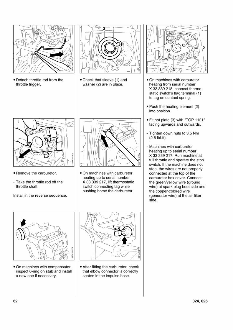
• Detach throttle rod from thethrottle trigger.
• Remove the carburetor.
- Take the throttle rod off thethrottle shaft.
Install in the reverse sequence.
• On machines with compensator,inspect 0-ring on stub and installa new one if necessary.
• Check that sleeve (1) andwasher (2) are in place.
• On machines with carburetorheating up to serial numberX 33 339 217, lift thermostaticswitch connecting tag whilepushing home the carburetor.
• After fitting the carburetor, checkthat elbow connector is correctlyseated in the impulse hose.
• On machines with carburetorheating from serial numberX 33 339 218, connect thermo-static switch’s flag terminal (1)to tag on contact spring.
• Push the heating element (2)into position.
• Fit hot plate (3) with "TOP 1121"facing upwards and outwards.
- Tighten down nuts to 3.5 Nm(2.6 lbf.ft).
- Machines with carburetorheating up to serial numberX 33 339 217: Run machine atfull throttle and operate the stopswitch. If the machine does notstop, the wires are not properlyconnected at the top of thecarburetor box cover. Connectthe green/yellow wire (groundwire) at spark plug boot side andthe copper-colored wire(generator wire) at the air filterside.
VA
133R
A23
9
VA
133R
A04
3
2 1
VA
133R
A24
4
2
1 3
TOP 1121
VA
133R
A24
0
VA
133R
A24
2V
A13
3RA
243
VA
133R
A24
1
62 024, 026
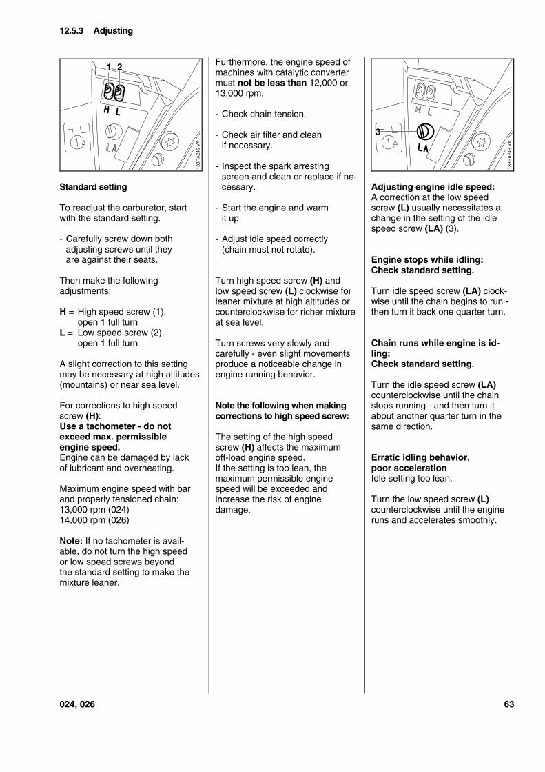
Standard setting
To readjust the carburetor, startwith the standard setting.
- Carefully screw down bothadjusting screws until theyare against their seats.
Then make the followingadjustments:
H = High speed screw (1),open 1 full turn
L = Low speed screw (2),open 1 full turn
A slight correction to this settingmay be necessary at high altitudes(mountains) or near sea level.
For corrections to high speedscrew (H):Use a tachometer - do notexceed max. permissibleengine speed.Engine can be damaged by lackof lubricant and overheating.
Maximum engine speed with barand properly tensioned chain:13,000 rpm (024)14,000 rpm (026)
Note: If no tachometer is avail-able, do not turn the high speedor low speed screws beyondthe standard setting to make themixture leaner.
Furthermore, the engine speed ofmachines with catalytic convertermust not be less than 12,000 or13,000 rpm.
- Check chain tension.
- Check air filter and cleanif necessary.
- Inspect the spark arrestingscreen and clean or replace if ne-cessary.
- Start the engine and warmit up
- Adjust idle speed correctly(chain must not rotate).
Turn high speed screw (H) andlow speed screw (L) clockwise forleaner mixture at high altitudes orcounterclockwise for richer mixtureat sea level.
Turn screws very slowly andcarefully - even slight movementsproduce a noticeable change inengine running behavior.
Note the following when makingcorrections to high speed screw:
The setting of the high speedscrew (H) affects the maximumoff-load engine speed.If the setting is too lean, themaximum permissible enginespeed will be exceeded andincrease the risk of enginedamage.
Adjusting engine idle speed:A correction at the low speedscrew (L) usually necessitates achange in the setting of the idlespeed screw (LA) (3).
Engine stops while idling:Check standard setting.
Turn idle speed screw (LA) clock-wise until the chain begins to run -then turn it back one quarter turn.
Chain runs while engine is id-ling:Check standard setting.
Turn the idle speed screw (LA)counterclockwise until the chainstops running - and then turn itabout another quarter turn in thesame direction.
Erratic idling behavior,poor accelerationIdle setting too lean.
Turn the low speed screw (L)counterclockwise until the engineruns and accelerates smoothly.
12.5.3 Adjusting
VA
133R
A24
5
21
VA
133R
A24
6
3
024, 026 63
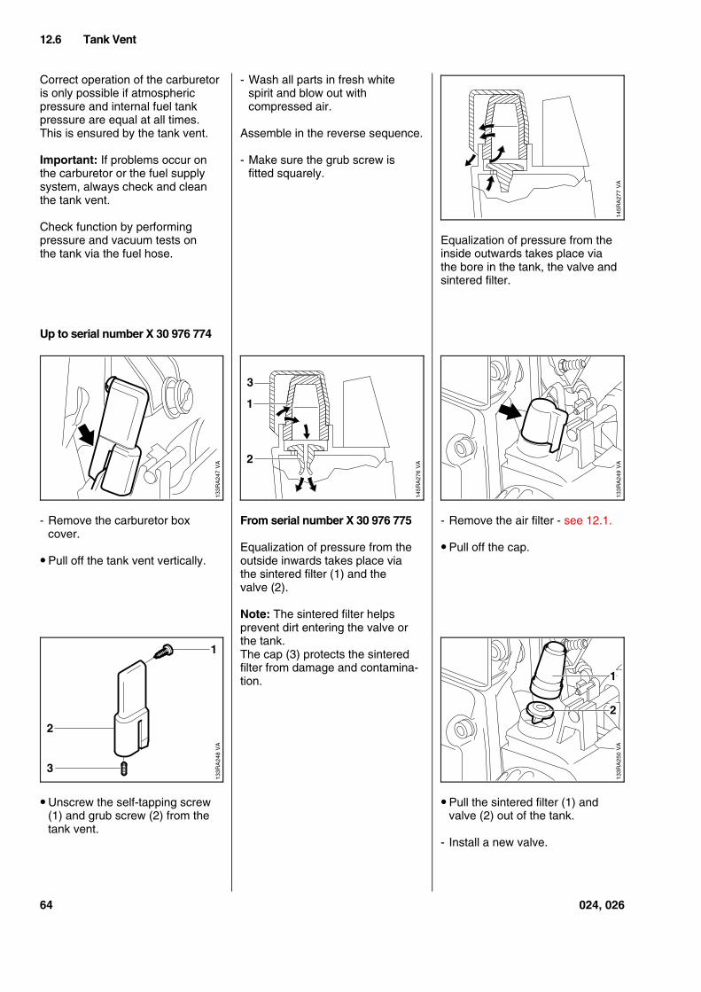
Correct operation of the carburetoris only possible if atmosphericpressure and internal fuel tankpressure are equal at all times.This is ensured by the tank vent.
Important: If problems occur onthe carburetor or the fuel supplysystem, always check and cleanthe tank vent.
Check function by performingpressure and vacuum tests onthe tank via the fuel hose.
Up to serial number X 30 976 774
- Remove the carburetor boxcover.
• Pull off the tank vent vertically.
• Unscrew the self-tapping screw(1) and grub screw (2) from thetank vent.
- Wash all parts in fresh whitespirit and blow out withcompressed air.
Assemble in the reverse sequence.
- Make sure the grub screw isfitted squarely.
From serial number X 30 976 775
Equalization of pressure from theoutside inwards takes place viathe sintered filter (1) and thevalve (2).
Note: The sintered filter helpsprevent dirt entering the valve orthe tank.The cap (3) protects the sinteredfilter from damage and contamina-tion.
Equalization of pressure from theinside outwards takes place viathe bore in the tank, the valve andsintered filter.
- Remove the air filter - see 12.1.
• Pull off the cap.
• Pull the sintered filter (1) andvalve (2) out of the tank.
- Install a new valve.
12.6 Tank Vent
VA
145R
A27
7
VA
133R
A24
7
VA
145R
A27
6
3
1
2
VA
133R
A24
9
VA
133R
A24
8
1
3
2
VA
133R
A25
0
1
2
64 024, 026
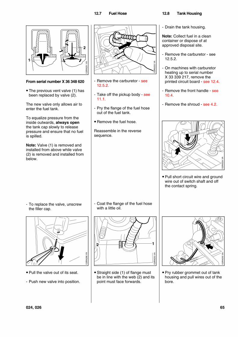
From serial number X 36 348 620
• The previous vent valve (1) hasbeen replaced by valve (2).
The new valve only allows air toenter the fuel tank.
To equalize pressure from theinside outwards, always openthe tank cap slowly to releasepressure and ensure that no fuelis spilled.
Note: Valve (1) is removed andinstalled from above while valve(2) is removed and installed frombelow.
- To replace the valve, unscrewthe filler cap.
• Pull the valve out of its seat.
- Push new valve into position.
- Remove the carburetor - see12.5.2.
- Take off the pickup body - see11.1.
- Pry the flange of the fuel hoseout of the fuel tank.
• Remove the fuel hose.
Reassemble in the reversesequence.
- Coat the flange of the fuel hosewith a little oil.
• Straight side (1) of flange mustbe in line with the web (2) and itspoint must face forwards.
- Drain the tank housing.
Note: Collect fuel in a cleancontainer or dispose of atapproved disposal site.
- Remove the carburetor - see12.5.2.
- On machines with carburetorheating up to serial numberX 33 339 217, remove theprinted circuit board - see 12.4.
- Remove the front handle - see10.4.
- Remove the shroud - see 4.2.
• Pull short circuit wire and groundwire out of switch shaft and offthe contact spring.
• Pry rubber grommet out of tankhousing and pull wires out of thebore.
12.7 Fuel Hose 12.8 Tank Housing
VA
133R
A25
1
1
2
VA
133R
A25
2
VA
133R
A25
4
VA
133R
A26
6
VA
133R
A25
3
2 1
VA
133R
A25
5
024, 026 65
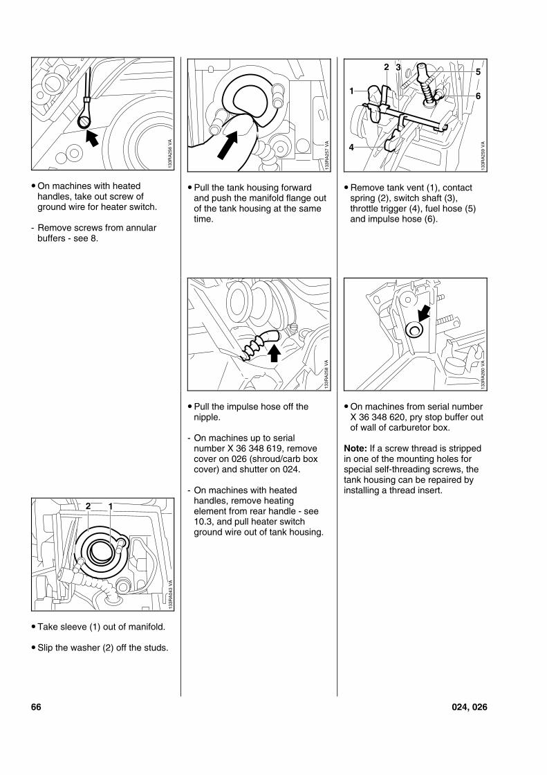
• On machines with heatedhandles, take out screw ofground wire for heater switch.
- Remove screws from annularbuffers - see 8.
• Take sleeve (1) out of manifold.
• Slip the washer (2) off the studs.
• Pull the tank housing forwardand push the manifold flange outof the tank housing at the sametime.
• Pull the impulse hose off thenipple.
- On machines up to serialnumber X 36 348 619, removecover on 026 (shroud/carb boxcover) and shutter on 024.
- On machines with heatedhandles, remove heatingelement from rear handle - see10.3, and pull heater switchground wire out of tank housing.
• Remove tank vent (1), contactspring (2), switch shaft (3),throttle trigger (4), fuel hose (5)and impulse hose (6).
• On machines from serial numberX 36 348 620, pry stop buffer outof wall of carburetor box.
Note: If a screw thread is strippedin one of the mounting holes forspecial self-threading screws, thetank housing can be repaired byinstalling a thread insert.
133R
A25
6V
A
VA
133R
A25
7
VA
133R
A25
94
61
2 3 5
VA
133R
A25
8
VA
133R
A26
0
VA
133R
A04
3
2 1
66 024, 026
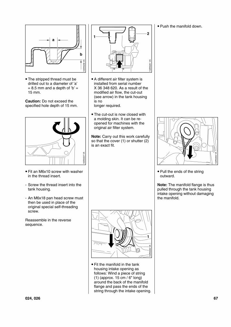
• The stripped thread must bedrilled out to a diameter of ’a’= 8.5 mm and a depth of ’b’ =15 mm.
Caution: Do not exceed thespecified hole depth of 15 mm.
• Fit an M6x10 screw with washerin the thread insert.
- Screw the thread insert into thetank housing.
- An M6x18 pan head screw mustthen be used in place of theoriginal special self-threadingscrew.
Reassemble in the reversesequence.
• A different air filter system isinstalled from serial numberX 36 348 620. As a result of themodified air flow, the cut-out(see arrow) in the tank housingis nolonger required.
• The cut-out is now closed witha molding skin. It can be re-opened for machines with theoriginal air filter system.
Note: Carry out this work carefullyso that the cover (1) or shutter (2)is an exact fit.
• Fit the manifold in the tankhousing intake opening asfollows: Wind a piece of string(1) (approx. 15 cm / 6" long)around the back of the manifoldflange and pass the ends of thestring through the intake opening.
• Push the manifold down.
• Pull the ends of the stringoutward.
Note: The manifold flange is thuspulled through the tank housingintake opening without damagingthe manifold.
VA
145R
A20
6
a
b
VA
133R
A26
1
21
VA
145R
A20
7
133R
A26
3V
A
VA
133R
A26
2
1
024, 026 67
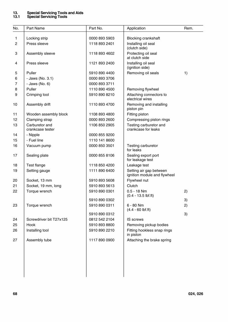
No. Part Name Part No. Application Rem.
1 Locking strip 0000 893 5903 Blocking crankshaft2 Press sleeve 1118 893 2401 Installing oil seal
(clutch side)3 Assembly sleeve 1118 893 4602 Protecting oil seal
at clutch side4 Press sleeve 1121 893 2400 Installing oil seal
(ignition side)5 Puller 5910 890 4400 Removing oil seals 1)6 - Jaws (No. 3.1) 0000 893 37067 - Jaws (No. 6) 0000 893 37118 Puller 1110 890 4500 Removing flywheel9 Crimping tool 5910 890 8210 Attaching connectors to
electrical wires10 Assembly drift 1110 893 4700 Removing and installing
piston pin11 Wooden assembly block 1108 893 4800 Fitting piston12 Clamping strap 0000 893 2600 Compressing piston rings13 Carburetor and 1106 850 2905 Testing carburetor and
crankcase tester crankcase for leaks14 - Nipple 0000 855 920015 - Fuel line 1110 141 860016 Vacuum pump 0000 850 3501 Testing carburetor
for leaks17 Sealing plate 0000 855 8106 Sealing export port
for leakage test18 Test flange 1118 850 4200 Leakage test19 Setting gauge 1111 890 6400 Setting air gap between
ignition module and flywheel20 Socket, 13 mm 5910 893 5608 Flywheel nut21 Socket, 19 mm, long 5910 893 5613 Clutch22 Torque wrench 5910 890 0301 0.5 - 18 Nm 2)
(0.4 - 13.5 lbf.ft)5910 890 0302 3)
23 Torque wrench 5910 890 0311 6 - 80 Nm 2)(4.4 - 60 lbf.ft)
5910 890 0312 3)24 Screwdriver bit T27x125 0812 542 2104 IS screws25 Hook 5910 893 8800 Removing pickup bodies26 Installing tool 5910 890 2210 Fitting hookless snap rings
in piston27 Assembly tube 1117 890 0900 Attaching the brake spring
13. Special Servicing Tools and Aids13.1 Special Servicing Tools
68 024, 026
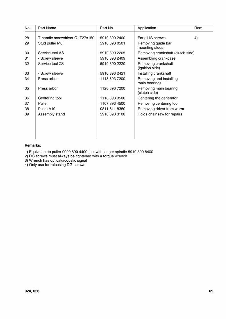
No. Part Name Part No. Application Rem.
28 T-handle screwdriver QI-T27x150 5910 890 2400 For all IS screws 4)29 Stud puller M8 5910 893 0501 Removing guide bar
mounting studs30 Service tool AS 5910 890 2205 Removing crankshaft (clutch side)31 - Screw sleeve 5910 893 2409 Assembling crankcase32 Service tool ZS 5910 890 2220 Removing crankshaft
(ignition side)33 - Screw sleeve 5910 893 2421 Installing crankshaft34 Press arbor 1118 893 7200 Removing and installing
main bearings35 Press arbor 1120 893 7200 Removing main bearing
(clutch side)36 Centering tool 1118 893 3500 Centering the generator37 Puller 1107 893 4500 Removing centering tool38 Pliers A19 0811 611 8380 Removing driver from worm39 Assembly stand 5910 890 3100 Holds chainsaw for repairs
Remarks:
1) Equivalent to puller 0000 890 4400, but with longer spindle 5910 890 84002) DG screws must always be tightened with a torque wrench3) Wrench has optical/acoustic signal4) Only use for releasing DG screws
024, 026 69
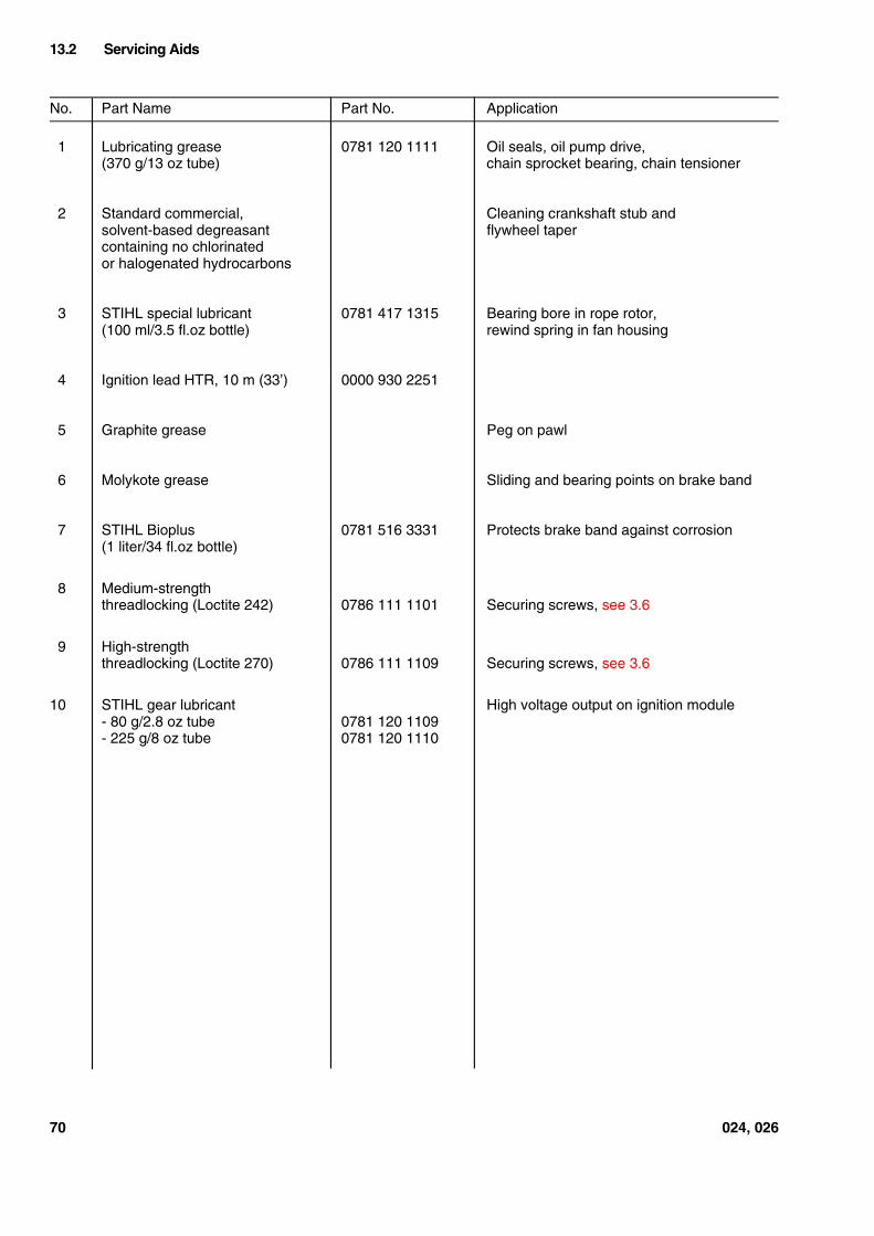
No. Part Name Part No. Application
1 Lubricating grease 0781 120 1111 Oil seals, oil pump drive,(370 g/13 oz tube) chain sprocket bearing, chain tensioner
2 Standard commercial, Cleaning crankshaft stub andsolvent-based degreasant flywheel tapercontaining no chlorinatedor halogenated hydrocarbons
3 STIHL special lubricant 0781 417 1315 Bearing bore in rope rotor,(100 ml/3.5 fl.oz bottle) rewind spring in fan housing
4 Ignition lead HTR, 10 m (33’) 0000 930 2251
5 Graphite grease Peg on pawl
6 Molykote grease Sliding and bearing points on brake band
7 STIHL Bioplus 0781 516 3331 Protects brake band against corrosion(1 liter/34 fl.oz bottle)
8 Medium-strengththreadlocking (Loctite 242) 0786 111 1101 Securing screws, see 3.6
9 High-strengththreadlocking (Loctite 270) 0786 111 1109 Securing screws, see 3.6
10 STIHL gear lubricant High voltage output on ignition module- 80 g/2.8 oz tube 0781 120 1109- 225 g/8 oz tube 0781 120 1110
13.2 Servicing Aids
70 024, 026