03 section 2 - project description - pengrowth energy files... · 2.7.1 water management ... 2.8.6...
TRANSCRIPT

Section 2 Project Description

Pengrowth Lindbergh SAGD Project Section 2 – Project Description
December 2011 Page 2-i
TABLE OF CONTENTS
Page
2 PROJECT DESCRIPTION ................................................................................................. 1
2.1 PROJECT OVERVIEW ...................................................................................................... 1
2.2 SITE SELECTION OF PROJECT FACILITIES .................................................................... 1
2.3 BITUMEN EXTRACTION AND PROCESSING COMPONENTS ............................................ 2
2.3.1 Well Pairs ............................................................................................................... 2
2.3.2 Well Pads ............................................................................................................... 2
2.4 CENTRAL PROCESSING FACILITY .................................................................................. 2
2.4.1 Gas Flaring System ............................................................................................... 5
2.5 MATERIAL AND ENERGY BALANCE ............................................................................... 6
2.5.1 Material Balance ................................................................................................... 6
2.5.2 Energy Balance...................................................................................................... 7
2.6 UTILITY AND TRANSPORTATION COMPONENTS ............................................................ 8
2.7 SITE MANAGEMENT ....................................................................................................... 9
2.7.1 Water Management .............................................................................................. 9
2.7.2 Surface Water Management .............................................................................. 10
2.7.3 Sewage Treatment ............................................................................................... 11
2.7.4 Waste Management Program ............................................................................ 11
2.8 HEALTH, SAFETY AND ENVIRONMENTAL MANAGEMENT .......................................... 15
2.8.1 General ................................................................................................................. 15
2.8.2 Corporate Policies ............................................................................................... 16
2.8.3 Health and Safety Program ................................................................................ 16
2.8.4 Emergency Response Plan ................................................................................. 17
2.8.5 Environmental Protection Program .................................................................. 18
2.8.6 Health, Safety and Environment Integration into Project Management ...... 18
2.8.7 Fire Control Plan ................................................................................................ 19
2.8.8 Worker Competence and Training Program ................................................... 19

Pengrowth Lindbergh SAGD Project Section 2 – Project Description
December 2011 Page 2-ii
List of Tables
Page
Table 2.4-1 External Emission Sources – Central Processing Facility ...................................... 4
Table 2.4-2 Storage Tanks Associated with the Central Processing Facility ............................. 4
Table 2.4-3 Chemical Use .......................................................................................................... 5
Table 2.5-1 Water Balance for the CPF (Steady State Case) ..................................................... 6
Table 2.5-2 Energy Balance ....................................................................................................... 7
Table 2.7-1 Waste Management Plan ....................................................................................... 13
List of Figures
Figure 2.4-1 Central Processing Facility Plot Plan

Pengrowth Lindbergh SAGD Project Section 2 – Project Description
December 2011 Page 2-1
2 PROJECT DESCRIPTION 2.1 PROJECT OVERVIEW
The facilities Pengrowth is proposing for the Lindbergh SAGD Project (the Project) include a number of wells pads and associated infrastructure such as well pairs, roads, above ground gathering and distribution systems, power lines, and a Central Processing Facility (CPF) (Figure 1.3-1). In addition, existing infrastructure such as the North Saskatchewan River intake, pump station, source water pond at the pilot plant, and pipeline will utilized for the Project. A raw water pipeline from the source water pond to the CPF will be installed and buried. Dual buried water disposal pipelines from the CPF to the existing water disposal well infrastructure will also be installed. A gas pipeline will be tied into a nearby third party gas distribution system and an overhead power line will be installed from the nearest sub-station to the CPF. A small islanded cogeneration unit will be constructed as part of the CPF to provide power for local use in the plant and wells.
Raw water and produced water will be treated at the CPF and re-used to generate steam which will be sent to each of the well pads via above ground pipelines for injection into the individual well pairs. Produced fluids (bitumen, water, gas) will be transported from the well pads to the CPF via above ground pipelines. The bitumen, water and gas will be separated at the CPF. The produced gas will be burned in the steam generators, the bitumen will be blended and trucked to a marketing point, and the water will be recycled.
The Lindbergh SAGD Project will produce a maximum annualized average bitumen rate of 1,987 m3/d (12,500 bpd) with an expected Project life of 25 years. Over the life of the Project there will be 60 to 65 well pairs drilled from approximately eight to nine well pads. This Project is expected to produce approximately 17.0 MMm3 (107 MMbbls) of bitumen. The cumulative steam to oil ratio (CSOR) for the Project is expected to be 3.62.
2.2 SITE SELECTION OF PROJECT FACILITIES
The criteria used to select the location of the CPF, pads, and other infrastructure considered were:
the CPF to be centrally located to the exploitable resource;
the CPF to be located in an area in which there is none or only a thin bitumen pay interval;
the well pads to be located to allow maximum contact with the bitumen resource without interfering with other surface rights holders;

Pengrowth Lindbergh SAGD Project Section 2 – Project Description
December 2011 Page 2-2
the location of the facilities and infrastructure to be kept away from sensitive environmental features such as rare plants or rare plant communities and any CNT area (Consultative Notation Area);
the facilities to be located in areas with minimum amount of muskeg or wetlands;
the facilities to be located in an area with minimal slopes; and
the location to be selected to minimize the length of corridors and minimize the ground disturbance.
2.3 BITUMEN EXTRACTION AND PROCESSING COMPONENTS
2.3.1 WELL PAIRS
The SAGD process involves drilling multiple vertically stacked well pairs. The bottom wells are the production wells through which the fluids are removed from the reservoir and lifted to surface. The injectors are spaced 5 m above the producers along the same trajectory. Steam is injected down dual tubing strings within the injectors into the reservoir to provide the heat to mobilize the bitumen.
Initially, the Lindbergh SAGD Project will have 23 new well pairs drilled, completed, and tied into the proposed CPF. These well pairs will have an average 800 m long horizontal section and will be spaced 100 m apart from each other in the reservoir. The two existing Lindbergh SAGD Pilot Project well pairs will also be tied into the proposed CPF.
2.3.2 WELL PADS
Multiple well pairs will be drilled from each well pad to minimize the surface disturbance and infrastructure requirements. It is anticipated that eight to nine well pads will be required over the life of the Project. Each well pad will have six to eight well pairs per pad as determined from geological, environmental, technical, and economic considerations.
Facilities located on the well pads include wellheads, testing equipment, manifold buildings, and miscellaneous other equipment. The pads will be connected to the CPF with above ground pipelines to transport the produced emulsion, casing vent gases, steam, and fuel gas.
2.4 CENTRAL PROCESSING FACILITY
The Central Processing Facility will be located in the SW ¼ of Section 25 in Township 58, Range 5 W4M (Figure 1.3-1).

Pengrowth Lindbergh SAGD Project Section 2 – Project Description
December 2011 Page 2-3
The CPF is comprised of the following components:
Oil production system;
Produced water de-oiling system;
Oil recycle and treatment system;
Produced water treatment system and boiler feed water;
Make-up water;
Steam generation system;
Fuel gas and produced gas recovery system;
Gas flaring system;
Glycol heating and cooling systems; and
Above ground interconnecting pipeline system.
Pengrowth will use well established processes for separating and treating the bitumen, water, and gas produced from the SAGD wells. Diluent will be utilized in the process to enable gravity separation and to enhance the flow characteristics of the bitumen through the process. The facility will be designed to produce 1,987 m3/d of bitumen at a steam-oil ratio of 3.62.
The produced water will be treated using an evaporation-distillation process in which over 90% of the produced water is re-used to generate steam. The facilities will be equipped with truck loading/unloading stations to handle receipt of diluent and shipments of blended diluent and bitumen (dil-bit).
Fuel gas will be supplied to the CPF via connection to a third party gas distribution system. The facility will be equipped with a cogeneration facility capable of supplying the electrical needs of the CPF and well pads. A tie-in to a nearby ATCO power substation will also be completed in order to ensure full backup power is available during periods in which the cogeneration unit is down for maintenance or repairs.
The total disturbance footprint of the CPF is approximately 24 ha with approximate dimensions of 750 m x 325 m. Figure 2.4-1 shows the plot plan for the CPF. Included on this drawing are the locations of buildings, flare stacks and storage tanks. Table 2.4-1 and Table 2.4-2 respectively list the external emission sources and storage tanks associated with the CPF. Dispersion modeling associated with these emission points is discussed in detail in the “Air Quality Report” (CR#1). A summary of this report is provided in Section 4.1.

Pengrowth Lindbergh SAGD Project Section 2 – Project Description
December 2011 Page 2-4
Table 2.4-1 External Emission Sources – Central Processing Facility
Name
Design Predicted Emissions (t/d)
# Stack
Height (m)SO2 NOx CO PM2.5
Cogeneration Unit Exhaust Stack 1 25 0.001 0.97 0.33 0.010
Steam Generator Exhaust Stack 3 30 0.29 0.25 0.22 0.02
Flare Stack – CPF1 1 40
Emergency Generator Stack1 2 4
Glycol Heater Exhaust Stack 1 10 0.0 0.007 0.011 0.001
Utility Steam Generator Stack 1 10 0.0 0.008 0.013 0.001 1 Not continuous emissions. Upset/flare scenarios run in model.
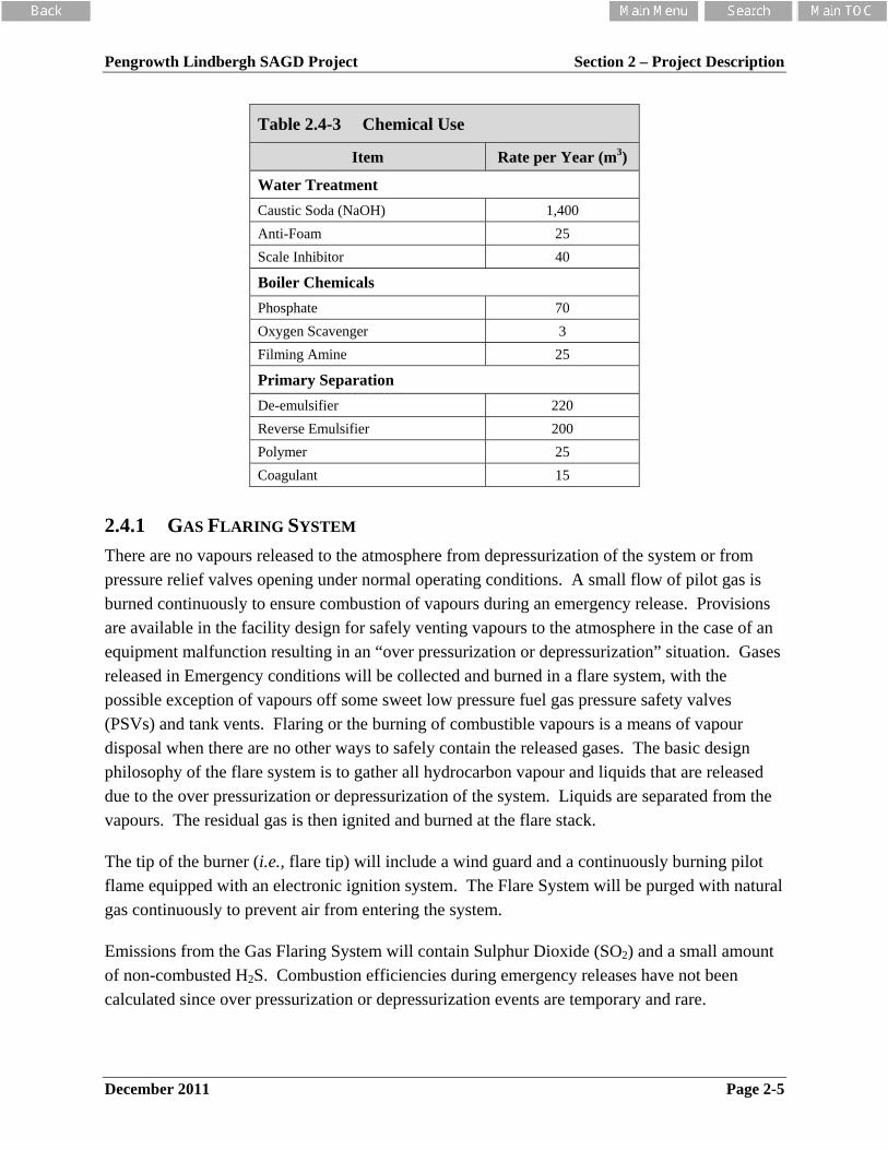
Table 2.4-3 lists the approximate annual quantities of chemicals used for the Project.
Table 2.4-2 Storage Tanks Associated with the Central Processing Facility
Name Product Volume (m3) Number
Diluent Storage Diluent 1,600 1
De-sand Tank Sediment & Water 400 2
Produced Water Surge Tank Water 1,600 1
Sales Oil Storage Tank Dil-Bit 1,600 1
Production Oil Storage Tank Dil-Bit 1,600 1
Off Specification Bitumen Storage Tank Dil-Bit 1,600 1
Produced Water Skim Tank Water & Oil 1,600 1
Waste Oil Storage Tank (Slop Oil Tank) Oily Water 400 1
De-Oiled Water Storage Tank De-oiled Water 1,600 1
Raw Water Storage Tank Water 400 1
Evaporator Feed Tank De-oiled Water 30 1
Caustic Storage Tank Sodium Hydroxide 30 1
Boiler Feed Water Tank Treated Water 1,600 1
Waste Brine Tank Evaporator Waste
Water 400 1
Boiler Blowdown Tank Water 320 1
Glycol Storage Tank Glycol & Water 32 1
Diesel Storage Tank Diesel 16 1
Floor Drain Tank Oil & Water 80 1
* Dil-Bit refers to a Diluent – Bitumen mixture
Pengrowth Lindbergh SAGD Project Section 2 – Project Description
December 2011 Page 2-5
Table 2.4-3 Chemical Use
Item Rate per Year (m3)
Water Treatment
Caustic Soda (NaOH) 1,400
Anti-Foam 25
Scale Inhibitor 40
Boiler Chemicals
Phosphate 70
Oxygen Scavenger 3
Filming Amine 25
Primary Separation
De-emulsifier 220
Reverse Emulsifier 200
Polymer 25
Coagulant 15
2.4.1 GAS FLARING SYSTEM
There are no vapours released to the atmosphere from depressurization of the system or from pressure relief valves opening under normal operating conditions. A small flow of pilot gas is burned continuously to ensure combustion of vapours during an emergency release. Provisions are available in the facility design for safely venting vapours to the atmosphere in the case of an equipment malfunction resulting in an “over pressurization or depressurization” situation. Gases released in Emergency conditions will be collected and burned in a flare system, with the possible exception of vapours off some sweet low pressure fuel gas pressure safety valves (PSVs) and tank vents. Flaring or the burning of combustible vapours is a means of vapour disposal when there are no other ways to safely contain the released gases. The basic design philosophy of the flare system is to gather all hydrocarbon vapour and liquids that are released due to the over pressurization or depressurization of the system. Liquids are separated from the vapours. The residual gas is then ignited and burned at the flare stack.
The tip of the burner (i.e., flare tip) will include a wind guard and a continuously burning pilot flame equipped with an electronic ignition system. The Flare System will be purged with natural gas continuously to prevent air from entering the system.
Emissions from the Gas Flaring System will contain Sulphur Dioxide (SO2) and a small amount of non-combusted H2S. Combustion efficiencies during emergency releases have not been calculated since over pressurization or depressurization events are temporary and rare.

Pengrowth Lindbergh SAGD Project Section 2 – Project Description
December 2011 Page 2-6
2.5 MATERIAL AND ENERGY BALANCE
2.5.1 MATERIAL BALANCE
2.5.1.1 Water
The water material balance (steady state case) for the Lindbergh SAGD Project is listed in Table 2.5-1. A produced water re-cycle rate of approximately 97% is expected. A steady state average of 256 m3/day of make-up feed water will be required for the project to replace water volumes lost to the process, utility services, and concentrated brine. The actual daily volume of make-up water required will vary significantly depending on reservoir performance (circulation phase, early production phase, normal production phase, blowdown phase, etc.).
Table 2.5-1 Water Balance for the CPF (Steady State Case)
Source (m3/d) Destination (m3/d)
Supply Water Balance
Raw Water from Pipeline 256
Average Brine Regeneration Waste from Softeners 8
Utility Water Consumption 10
RO Reject to Evaporator 59
Soft RO Water to BFW Tank 179
Evaporator Balance
Deoiled Water to Evaporators 7,188
Boiler Blowdown to Evaporators 223
RO Reject to Evaporators 59
Distillate from Evaporators 7,244
Waste Brine from Evaporators (to Disposal) 226
Steam Generation Balance
BFW to Steam Generators 7,423
Steam to Reservoir (Cold Water Equivalent [CWE]) 7,200
Boiler Blowdown to Evaporator 223
Reservoir Balance
Steam to Reservoir (CWE) 7,200
Formation Water Production 0
Produced Water from Reservoir 7,200
Water Lost to Reservoir 0

Pengrowth Lindbergh SAGD Project Section 2 – Project Description
December 2011 Page 2-7
Table 2.5-1 Water Balance for the CPF (Steady State Case)
Source (m3/d) Destination (m3/d)
CPF Production Water Balance
Water from Field 7,200
Water Losses to Process (dil-bit, fuel gas, etc) 12
Water to Evaporators 7,188
Produced Water to Disposal 0
Note: Does not include any water losses in trucked-out waste products (slop oil, de-sand waste, etc) as this is not expected to a regular occurrence.
ERCB Draft Directive February 2009 Calculations:
Requirements for Water Measurement, Reporting and Use for Thermal In Situ Oil Sands Schemes
Fresh Water Make Up = 3.4%
Produced Water Re-Use = 96.6%
2.5.1.2 Hydrocarbon Liquids
During peak operation, 8,282 Sm3/day of production fluids will be delivered as emulsion from the well pads to the CPF. Of the total volume, approximately 1,956 Sm3/day is bitumen and 6,326 Sm3/day is water. The bitumen is blended with 400 Sm3/d of diluent in order to treat the bitumen to meet the 0.5% BSW (Basic Sediment and Water) sales specification. A total volume of 2,397 m3/day of dilbit product will be trucked from the CPF gate. All vapours within the process are cooled to condense water and hydrocarbons, which are separated and returned to the bitumen extraction process. The remaining hydrocarbon gas is combined into the fuel gas stream and consumed in the SAGD process.
2.5.2 ENERGY BALANCE
Table 2.5-2 shows an energy balance for the Project.
Table 2.5-2 Energy Balance
Total Energy IN
Bitumen from Wells
Bitumen Production (m3/d) 1,987
Bitumen Density (kg/m3) 1,000.44
Bitumen Production (t/d) 1,988.2
Bitumen LHV (kJ/kg) 43,745
Chemical Energy Flow (GJ/d) 86,975
Reservoir Gas
Reservoir Gas Volume (Sm3/d dry) 39,747
Reservoir Gas LHV (MJ/Sm3) 25.33

Pengrowth Lindbergh SAGD Project Section 2 – Project Description
December 2011 Page 2-8
Table 2.5-2 Energy Balance
Total Energy IN
Chemical Energy Flow (GJ/d) 1,007
Diluent Feed
Diluent Rate (m3/d) 400
Diluent Density (kg/m3) 700
Diluent from Truck (t/d) 280.00
Diluent LHV (kJ/kg) 44,285
Chemical Energy Flow (GJ/d) 12,400
Natural Gas
Fuel Gas for CPF (Sm3/d) 471,341
Fuel Gas LHV (MJ/Sm3) 34.48
Chemical Energy Flow (GJ/d) 16,250
Electricity Import
Electrical Power (MW) 0.00
Electrical Power (GJ/d) 0
Total Energy OUT
Saleable Products (Dil-Bit)
Dil-Bit Product (t/d dry) 2,268
Dil-Bit LHV (kJ/kg) 43,812
Chemical Energy Flow (GJ/d) 99,374
Electrical Export
Electrical Power (MW) 0.00
Electrical Power (GJ/d) 0
Total Energy IN (GJ/d) 116,631
Total Energy OUT (GJ/d) 99,374
Energy Efficiency (%) 85.20
2.6 UTILITY AND TRANSPORTATION COMPONENTS
Figure 1.3-1 illustrates the location of the CPF, the initial well pads, and the corridors connecting the pads to the CPF. These corridors will contain access roads, above-ground pipelines, and overhead power lines. Figures 1.1-1 and 1.3-1 show the location of the North Saskatchewan River intake station and the source water pipeline route to the existing source water pond.

Pengrowth Lindbergh SAGD Project Section 2 – Project Description
December 2011 Page 2-9
This project is associated with the expansion of an existing project. A supply of sanitary and non-potable water is available in the existing office/maintenance building. This water is used for washrooms, showers, and office sanitary purposes.
Currently potable water is provided by a third party supplier for the Pilot Plant. This practice will remain for this expansion. A supply of potable water will be required for the construction camp, operations camp and the administration and control room offices at the new CPF.
The current source for sanitary water at the Pilot Plant is a shallow water well located at the CPF near the office/warehouse complex at SE 6-13-058-05 W4M. The well draws water from a depth of 230 m. A domestic water softener is located in the office building.
The CPF sanitary water will be supplied through an existing water source, the North Saskatchewan River. Water will be diverted from this source for consumption at the new CPF for washrooms, showers, and office utility purposes.
2.7 SITE MANAGEMENT
2.7.1 WATER MANAGEMENT
Regulatory requirements and guidelines for process water recycle are included in four main documents:
EUB Guide IL89-05 “Water Recycle Guidelines and Water Use Information”;
EUB-AENV Guide 89-AA “Water Recycle Guidelines and Reporting of Water Use Information for In-Situ Oil Sands Facilities in Alberta”;
ERCB Bulletin 2006-11 March 28, 2006, “Water Recycle, Reporting and Balancing Information for In-Situ Thermal Schemes”; and
ERCB Directive 17 October 22, 2009, “Measurement Requirements for Oil and Gas Operations”.
The guidelines have a goal of maximizing water recycling to reduce the freshwater requirements and wastewater disposal volumes associated with oil sands developments. All in-situ operators with freshwater requirements exceeding approximately 500,000 m3/year (500 dam3/year) are required to recycle produced water. The water management plan proposed by Pengrowth will include the recycling of produced water at a recycle rate of approximately 97%.
Anticipated water losses are comprised of the following:
losses in the reservoir;
brine off the evaporator;

Pengrowth Lindbergh SAGD Project Section 2 – Project Description
December 2011 Page 2-10
SAC Regen losses;
utility water consumption;
water entrained in the sales oil;
water saturation of the fuel gas; and
water losses to intermittent truck-out of slop oil or desand waste.
As the individual SAGD well pairs progress through their productive life cycle, the balance of water injected to water produced varies. During initial circulation of the well pairs, up to 20% of the water injected is expected to be retained in the reservoir. The amount of retained water will decrease during normal SAGD well pair production operations, and a potential excess of formation water may be produced. As the well pair nears the end of its productive life, the steam injection volume is decreased and eventually stopped. During this period, the well remains in production resulting in a surplus volume in the water-injected to water-produced balance.
It is anticipated that the Project will require 256 m3/day of steady state make-up water to replace the expected CPF operational water losses that cannot be recovered and recycled. For design purposes, reservoir water losses/gains were estimated at 0 m3/d.
2.7.2 SURFACE WATER MANAGEMENT
During site preparation, adequate drainage away from storage tanks, equipment, skids, buildings and pipe racks will be provided to direct the run off towards designated storm water retention ponds. Site preparation includes the following:
clearing the site by removing trees and plant roots;
stripping and stockpiling the topsoil;
removing unsuitable or excess material such as muskeg;
contouring the site to ensure proper site drainage;
constructing storm water retention pond(s);
applying, where necessary, appropriate sub-base material and compact bases for facilities complete with geotextile and asphalt spray; and
ensuring that appropriate, where necessary, secondary containment around facilities complete with geotextile and asphalt spray are in place.
2.7.2.1 Central Processing Facility
All regulated storage tanks will be equipped with secondary containment and leak detection to minimize the occurrence of product leaks and subsequent contamination to the environment.

Pengrowth Lindbergh SAGD Project Section 2 – Project Description
December 2011 Page 2-11
Surface water run-off from the plant site will be directed to a storm water retention pond located to take advantage of the natural elevation gradient. The retention pond will be constructed in accordance with ERCB Directive 55 regulations. All surface runoff will be collected in the settling pond and returned to the CPF for use as plant make-up water. It is anticipated that periodically, depending upon site and operating conditions, excess surface runoff collected in the settling pond will be released into the surrounding watershed. Prior to discharge, the water will be tested and released in accordance with the terms and conditions of the operating approval.
The CPF storm water retention pond design will be based on the “Environmental Protection and Enhancement Act Approvals and Registrations Applications for Sour Gas Processing Plants and Heavy Oil Plants A Guide to Content – Appendix B” (AENV, 1999a). The pond is required to hold the runoff from a 10-year 24-hour rainfall (64.7 mm). The required storage for the 24.1 ha area of the CPF is estimated to be about 9,340 m3 using a runoff coefficient of 0.6 (0.6 x 0.0647 m x 240,600 m2 = 9340 m3). This runoff volume can be stored in a 100 m by 40 m by 2.5 m deep pond. The peak flow rate into the pond for this 10-year 24-hour event is 0.11 m3/s. Peak flow rates into the pond for shorter duration, higher intensity events will be greater but volumes will be less. The peak 10-year flow rate into the pond is estimated to be 1.7 m3/s based on the rainfall intensity of 43 mm/hr for an estimated time of concentration of 30 minutes.
2.7.2.2 Well Pads and Roads
All Well Pads and roads will be constructed in a manner to minimize erosion from surface water runoff. This will be achieved utilizing appropriate collection areas and flow barriers where necessary. Ditches will be designed to avoid ponding of water along road surface. Natural flows will be maintained across drainages and wetlands with the appropriate use of culverts.
2.7.3 SEWAGE TREATMENT
Domestic sewage will be directed through an approved sewer system to a septic field or will be trucked to an approved disposal location. The system will meet all provincial and local codes.
2.7.4 WASTE MANAGEMENT PROGRAM
A waste management plan for the Project will be designed to effectively control waste during the construction and the operational phase of the Project. This waste management plan will minimize waste generation by reducing, reusing or recycling as much of the waste as possible. Disposition methods and location for each type of waste will be outlined. Part of the waste management plan is to implement a feedback system which allows for measurement of the plan’s effectiveness and identification of areas in need of improvement.

Pengrowth Lindbergh SAGD Project Section 2 – Project Description
December 2011 Page 2-12
Waste management at the site will comply with the following waste management processes, procedures and guidelines including the EPEA Waste Control Regulation (AEP 1996). Practices will include:
classifying, measuring and controlling waste generation;
handling, storage, treatment and disposal;
tracking and reporting;
off-site disposal of dangerous oilfield waste (DOW) and non-DOW wastes as appropriate; and
recycling as appropriate.
Waste management practices will meet or exceed the requirements of the ERCB. Specifically, these management requirements are outlined in both Directive 58 (Oilfield Waste Management Requirements for the Upstream Petroleum Industry) (ERCB 1996a) and Directive 50 (Drilling Waste Management) (ERCB 1996b). Directive 58 requires the preparation of an Annual Oilfield Waste Disposition Report, which summarizes the types and quantities of disposed oilfield waste, the points of generation and the disposal methods utilized.
The waste generated by the project is categorized in two stages. The first stage is consisted of waste generated during the construction phase of the project. The second stage is during the on-going operations of the facility throughout the life of the Project. Some of the waste that will be generated during the construction phase will come from the construction and operation of a camp, construction of roads, the plant site and well pads, and steam distribution and liquid transfer lines from the well pads to the CPF. The construction phase of the project will be approximately one year in duration. The life expectancy of Project operation is estimated to be 25 years.
Summaries of the wastes generated for each stage are shown in Table 2.7-1. The summary includes proposed storage locations, disposal sites, disposal method and estimated annual quantities/volumes produced.
Quantities of waste generated during operations have been estimated in the table by using process flow diagrams and material balance calculations. However, the quantities for construction waste and camp waste have not been determined. These will be disposed of in approved disposal facilities on an as-generated basis.

Pengrowth Lindbergh SAGD Project Section 2 – Project Description
December 2011 Page 2-13
Table 2.7-1 Waste Management Plan
Water Description ERCB Waste Code*
Storage Location
Disposal Responsibility
Disposal Method Annual Volume
Construction
Packing Materials DOMWST Bins Contractor Incinerator/Recycle As Generated
Pallets DOMWST Bins Contractor Incinerator/Recycle As Generated
Wood CONMAT Bins Contractor Incinerator/Recycle As Generated
Scrap Metal SMETAL Bins Contractor Landfill/Recycle As Generated
Glass CONMAT Bins Contractor Landfill/Recycle As Generated
Paint WPAINT Bins Contractor Recycle As Generated
Sand blast CONMAT Bins Contractor CL2 LF** As Generated
Insulation CONMAT Bins Contractor CL2 LF** As Generated
Welding Rods CONMAT Bins Contractor CL2 LF** As Generated
Lubricants LUBOIL Drums Contractor Recycle As Generated
Oil Filters FILLUB Drums Contractor Recycle As Generated
Construction – Camp
Kitchen Wastes DOMWST Bins Contractor Landfill As Generated
Cardboard DOMWST Bins Contractor Landfill/Recycle As Generated
Containers EMTCON Bins Contractor Incinerator As Generated
Septic Fluids WSTMIS Septic System
Contractor Digestor/Contractor As Generated
Operations – Drilling
Drilling Mud/Cuttings
Various Tank Contractor Recycle or MBC** As Generated
Lubricants LUBOIL Drums Contractor Recycle As Generated
Mud Additives Various Bins Contractor Return or Recycle As Generated
Scrap Metal SMETAL Bins Contractor Landfill/Recycle As Generated
Pallets DOMWST Bins Contractor Incinerator/Recycle As Generated
Cement CEMENT Bins Contractor CL2 LF** As Generated
Solvents Various Drums Contractor Return or Recycle As Generated
Mud Sacks EMTCON Bins Contractor CL2 LF** As Generated
Operations – CPF
Filter: Glycol FILGY Bins Swan Hills Swan Hills 0.1 m3
Filter: Raw Water FILFWT Bins Owner CL2 LF** 0.5 m3
Filter: Pressure FILOTH Bins Swan Hills Swan Hills 5.0 m3
Filter: Oil Removal FILOTH Bins Swan Hills Swan hills 4.0 m3
Ion Exchange Resins IEXRES Bins Owner CL2 LF** 50.0 m3
Filter Backwash Sludge/Liquid
WESTMIS Tank Owner Recycle

Pengrowth Lindbergh SAGD Project Section 2 – Project Description
December 2011 Page 2-14
Table 2.7-1 Waste Management Plan
Water Description ERCB Waste Code*
Storage Location
Disposal Responsibility
Disposal Method Annual Volume
Boiler Blowdown Water
WSTMIS Vessel Owner Recycle
Process Blowdown Water
WSTMIS Tank Owner Recycle
Septic Fluids WSTMIS Septic System
Owner Site Septic Field 800 m3
Caustic CAUS Tank Owner Recovery 986 m3/yr
Acid ACID Trucked in as needed
Third Party Return or Recycle
Batteries BATT Bins Owner Recycle
Containers: Drums/Barrels
EMTCON Bins Owner Return or Recycle
Containers: Herbicide PSTCON Bins Owner Return or Recycle
Containers: Pesticide PSTCON Bins Owner Return or Recycle
Containers: BIOCIDE
EMTCON Bins Owner Return or Recycle
Filters: Lube Oil LUBOIL Bins Third Party Recycle 0.5 m3/yr
Filters: Produced Oil FILWWT Bins Swan Hills Swan Hills As generated
Garbage: Office Paper
DOMWST Bins Owner Landfill/Recycle As generated
Pallets DOMWST Bins Owner Landfill/Recycle As generated
Packing Materials DOMWST Bins Contractor Recycle
Hydrotest Fluids: Methanol
METHNL Tank Contractor Recycle
Insulation CONMAT Bins Contractor CL2 LF** As generated
Lab. Chemicals – Spent
INOCHM/OR Drums Owner Recycle
Rags: Oily OILRAG Bins Owner CL2 LF** As generated
Sludge: Separators SLGPRO Tank Owner Recycle In produced
sand
Sludge: Oil Slop Tanks
SLYHYD Tank Owner Recover In produced
sand
Well Workover Fluids
WNOFLD Tank Contractor Bioremediation As generated

Pengrowth Lindbergh SAGD Project Section 2 – Project Description
December 2011 Page 2-15
Table 2.7-1 Waste Management Plan
Water Description ERCB Waste Code*
Storage Location
Disposal Responsibility
Disposal Method Annual Volume
Operations – Camp
Kitchen Waste DOMWST Bins Contractor Landfill As generated
Cardboard DOMWST Bins Contractor Landfill/Recycle As generated
Containers EMTCON Bins Contractor Landfill/Recycle As generated
Septic Fluids WSTMIS Septic System
Contractor Digestor As generated
Incinerator Ash INCASH Bin Contractor CL2 LF** As generated * ERCB Waste Codes are provided in Appendix 7 – Waste Listings of ERCB Directive 58 – Oilfield Waste Management
Requirements for the Upstream Petroleum (ERCB, 1996a)
** CL2LF – Class II Landfill
*** MBC – ERCB’s and AENV’s Mix Bury Cover Requirements
2.8 HEALTH, SAFETY AND ENVIRONMENTAL MANAGEMENT
2.8.1 GENERAL
Pengrowth is committed to conducting its business in a way that protects the health and safety of its employees and others involved in, or affected by Pengrowth's operations, including contractors and the general public. Pengrowth is committed to environmental protection and integration of the environment in all aspects of its business. Pengrowth works to ensure continual improvement of its health, safety, and environment (HSE) management systems through regular internal reviews and external audits. Pengrowth participates in the Alberta Partnerships Certificate of Recognition (COR) program and in the Canadian Association of Petroleum Producers (CAPP) Environment, Health, Safety, and Social Stewardship Program. In 2006, Pengrowth obtained re-certification of its COR. In 2007, Pengrowth received CAPP's Platinum Level recognition in support of its HSE program.
Pengrowth will provide responsible management for the Project by ensuring that health, safety, and environmental policies and procedures are established and implemented. The HSE Management Plan will include the development of a Safety Program specific to the Project. It will include the adoption of Pengrowth's HSE Handbook, Emergency Response Plan (ERP), and Training Programs. Pengrowth will integrate environment, health and safety into all Project components to ensure compliance with environmental, health and safety stewardship objectives.

Pengrowth Lindbergh SAGD Project Section 2 – Project Description
December 2011 Page 2-16
The Health and Safety Plan will include, but will not be limited to, the following:
adequate training of all owner, contractor and technical personnel;
initial safety orientation (pre-job safety meeting) prior to commencing any site work;
daily tailgate meetings to re-emphasize and identify potential hazards or health concerns;
selection of appropriate personal protective equipment for each activity; and
recognition of emergency situations and appropriate response.
2.8.2 CORPORATE POLICIES
Pengrowth's activities are guided by a Health and Safety Policy, an Environmental Policy, and the Petroleum Industry Guiding Principles for Worker Safety.
2.8.3 HEALTH AND SAFETY PROGRAM
Pengrowth is committed to conducting its operations in a safe manner. In support of this commitment, Pengrowth has developed a Health and Safety Management system based on the Alberta Partnerships COR program. To help ensure compliance and ongoing improvement of its Safety program, Pengrowth conducts internal and external audits to ensure the efficiency of the Safety Management system.
Pengrowth's Safety Handbook for employees and contractors includes an overview of the management system. The Safety Handbook is intended to provide management, employees and contractors with the tools, information and references they need to carry out safe work practices. All operators, supervisors and contractors are provided with an initial orientation to familiarize with company safe operating practices. Complementary documents, tools and training programs include Pengrowth's:
Hazard Identification and Risk Management program which includes a structured process for controlling work site hazards, including tools, machines and equipment, thus maintaining a safe working environment and minimizing the risk to Pengrowth employees, its contractors and the public;
Near miss and incident reporting program which requires all employees and contractors to participate in proactive reporting of all near misses and incidents. Key learning from these submissions and from audit and inspection reports are tracked by an internal incident tracking system and are shared with team members at scheduled safety communication meetings. These proactive efforts are targeted at raising safety awareness among team members in order to reduce the risk of future incidents or injuries;
Emergency Response Planning and Preparedness program which ensures that employee and public safety is accomplished by developing and maintaining ERPs for all Pengrowth

Pengrowth Lindbergh SAGD Project Section 2 – Project Description
December 2011 Page 2-17
facilities and drilling activities. These plans are updated regularly to ensure preparedness in the event of an emergency situation. Practice exercises and drills are conducted regularly to assure effectiveness of the Emergency Response Program and to comply with regulatory requirements;
Safety Communication - Pengrowth conducts regular safety communication meetings that are intended for group communication and information sharing. Employees and contractors are encouraged to provide input and practical recommendations for the continuous improvement of the safety program;
Safety Training Programs are conducted regularly to ensure that team members have the proper knowledge and skills necessary to work safely. For high risk activities, special training programs are provided. As driving is one of the highest risk activity, Pengrowth introduced a behaviour based driving initiative that focuses on traffic knowledge, driving attitude, and risk perception; and
Contractor Safety meetings are conducted in all operational areas prior to commencement of work. This allows for information sharing and informs the contractors on Pengrowth's work practices, procedures, and standards.
2.8.4 EMERGENCY RESPONSE PLAN
Pengrowth will develop a site-specific Emergency Response Plan (ERP) for the Project construction and operation phases that will set out procedures and will identify responsible personnel and third party support expertise to deal with emergency situations. This site-specific ERP will be referenced in Pengrowth's corporate ERP. The ERPs will address alert levels, evacuation requirements; call down procedures and external emergency agency involvement. The ERP will address incidents such as:
serious on site injury to facility personnel, contractors or members of the public;
CPF shutdown;
major equipment or instrumentation failure;
unplanned releases to the environment including pipeline failure;
fire in or near facilities;
security;
specific procedures for potential H2S releases; and
loss of well control.
The primary objectives of the ERP will be to limit the danger to facility personnel, the public, the environment, and operating equipment.

Pengrowth Lindbergh SAGD Project Section 2 – Project Description
December 2011 Page 2-18
2.8.5 ENVIRONMENTAL PROTECTION PROGRAM
Pengrowth's Environmental Management System is based upon the CAPP Stewardship program with the following components:
management and leadership;
environmental protection;
regulatory compliance;
emergency response;
employee training and awareness; and
stakeholder involvement and reporting.
Comprehensive measures will be developed and implemented for the design and operation of the Project to mitigate the occurrence and impact of environmental issues. Employees and contractors will be trained to operate equipment according to vendor recommendations and procedures. Workers will be trained to manage and respond to operating situations that may impact the environment. Pengrowth's environmental practices will be adopted and improved throughout the life of the Project.
Ongoing monitoring, assessments and audits will be carried out through the life of the Project on a regular basis to ensure Pengrowth's objectives, with respect to environmental stewardship, have been met.
2.8.6 HEALTH, SAFETY AND ENVIRONMENT INTEGRATION INTO PROJECT
MANAGEMENT
Pengrowth is following a comprehensive Project Management approach in which HSE matters are incorporated in all phases of the project. Prior to development, baseline conditions are evaluated and potential environmental and safety issues identified. HSE issues are included in
the early design and siting of facilities. Design work includes formal hazard identification and mitigation, as well as input from operations personnel into the design. Design and control requirements will be modified to minimize any potential negative operating impacts. Following this, a HSE plan will be implemented for construction. The next phase will involve monitoring and mitigating the potential environmental and safety incidents during operations in order to ensure the effects are prevented, minimized or mitigated. The final phase will occur at abandonment to demonstrate that all environmental and safety liabilities have been removed from the site's remaining footprint.

Pengrowth Lindbergh SAGD Project Section 2 – Project Description
December 2011 Page 2-19
2.8.7 FIRE CONTROL PLAN
Pengrowth will develop a wildfire control plan in consultation with the Forest Protection Division of Alberta Sustainable Resource Development (ASRD). The fire plan will address both the Project as a source of fire, and the impact of a wildfire on the Project. It will describe the equipment and emergency preparedness at the Project site to assist in wildfire control. It will also include maps of roads and accesses to Pengrowth's lease area to provide valuable information for the local forest protection division. Forest fire awareness will also be added to the training programs for Pengrowth employees.
Potential sources of fire resulting from the Project include operations within the CPF, the electrical distribution system, flare system and steam piping. "Fire Eye" sensors capable of detecting open flame will be installed in critical areas of the CPF and the well pad. In addition, combustible gas and smoke detectors will be located throughout the facility. All sensors will be tied into the process-control system to allow prompt response in the event of fire. Plans for fire suppression during the operation of the Project will require a combination of wall mounted and wheeled fire extinguishers located around the CPF and the well pad. In addition, operators' trucks will be outfitted with portable fire extinguishers. Other fire reduction measures will include:
use of non-combustible building materials;
where deemed appropriate, absence of combustible ground cover; and
adequate setback of facilities from the surrounding forest.
2.8.8 WORKER COMPETENCE AND TRAINING PROGRAM
Pengrowth has identified core HSE training requirements such as First Aid/ Cardiopulmonary resuscitation (CPR), Transportation of Dangerous Goods (TDG), Workplace Hazardous Materials Information Systems (WHMIS), H2S Alive, and other programs for various positions. These training requirements are tracked by each operational area to ensure all training remains current.
Pengrowth is also currently implementing a Competency Management and Development System (CMDS) developed by Keyera Energy. This is a comprehensive training development system for operations employees, based upon developing occupational profiles for various positions, self assessment, and using subject matter expert validation of work. Training is available using CD-ROM based materials, online training, or other instructor led seminars and training. This system will be adopted for the Project operations and will help ensure efficient, safe and environmentally responsible operations.

Pengrowth Lindbergh SAGD Project Section 2 – Project Description
December 2011
FIGURES

2.5-2DRAWN:
FILE: ...Final Docs\Applic\Fig 2.5-2 Plot Plans.dwg
CHECKED:
DATE:
PROJECT:
JG
KK
Dec 19/11
11-032
Central Processing Facility Plot Plan
TITLE:
PROJECT:
FIGURE:
REF: SCOVAN Engineering Inc., 2011.
Lindbergh SAGD Project
2.4-1