030-xxxa samba e - mr resistor lighting lyneo dual.pdf · uk installation technicalassistance...
TRANSCRIPT
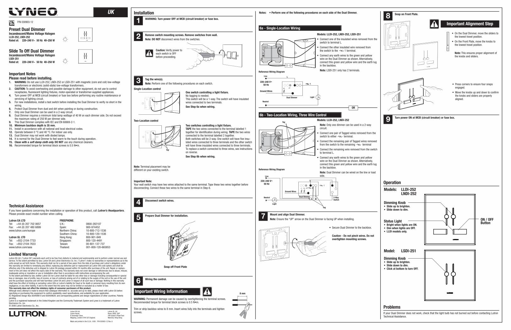
UK Installation
Technical AssistanceIf you have questions concerning the installation or operation of this product, call Lutron's Headquarters.Please provide exact model number when calling.
Lutron EA LTD FREEPHONE:Tel: +44 (0) 207 702 0657 U.K.: 0800-282107Fax: +44 (0) 207 480 6899 Spain: 900-974452www.lutron.com/europe Northern China: 10-800-712-1536
Southern China: 10-800-120-1536Lutron GL LTD Hong Kong: 800-901-849Tel: +852-2104-7733 Singapore: 800-120-4491Fax: +852-2104-7633 Taiwan: 00-801-137-737www.lutron.com/asia Thailand: 001-800-120-665853
Limited WarrantyLutron EA Ltd. (“Lutron EA”) warrants each unit to be free from defects in material and workmanship and to perform under normal use andservice. To the extent permitted by law, Lutron EA and Lutron Electronics Co. Inc. (“Lutron”) make no warranties or representations as to theunits except as set forth herein. This warranty shall run for a period of two years from the date of purchase and Lutron’s obligations underthis warranty are limited to remedying any defect, replacing any defective part or replacement (at Lutron EA’s sole option) and shall beeffective only if the defective unit is shipped to Lutron EA postage prepaid within 24 months after purchase of the unit. Repair or replace-ment of the unit does not affect the expiry date of the warranty. This warranty does not cover damage or deficiencies due to abuse, misuse,inadequate wiring or insulation or use or installation other than in accordance with instructions accompanying the unit.To the extent permitted by law, neither Lutron EA nor Lutron shall be liable for any other loss or damage including consequential or specialloss or damages, loss of profits, loss of income, or loss of contracts arising out of or relating to the supply of the unit or the use of the unitand the purchaser assumes and will hold harmless Lutron EA and Lutron in respect of all such loss or damage. Nothing in this warrantyshall have the effect of limiting or excluding Lutron EA’s or Lutron’s liability for fraud or for death or personal injury resulting from its ownnegligence, or any other liability, if and to the extent that the same may not be limited or excluded as a matter of law.This warranty does not affect the statutory rights of consumer purchasers of this product.Although every attempt is made to ensure that catalogue information is accurate and up-to-date, please check with Lutron EA beforespecifying or purchasing this equipment to confirm availability, exact specifications, and suitability for your application.EC Registered Design Nos 000409610 and 000409628; and corresponding patents and design registrations of other countries. Patentspending.Lutron is a registered trademark in the United Kingdom and the Community Trademark System and Lyneo is a trademark of LutronElectronics Co., Inc.© 2006 Lutron Electronics Co., Inc.
Important NotesPlease read before installing.1. WARNING: Do not use LLDI-252, LNDI-252 or LSDI-251 with magnetic (core and coil) low-voltage
transformers or electronic (solid-state) low-voltage transformers.2. CAUTION: To avoid overheating and possible damage to other equipment, do not use to control
receptacles, fluorescent lighting fixtures, motor-operated or transformer-supplied appliances.4. Turn power OFF at MCB (circuit breaker) or fuse box before performing any routine maintenance or
servicing of lighting circuit.5. For new installations, install a test switch before installing the Dual Dimmer to verify no short in the
wiring.6. Protect Dual Dimmer from dust and dirt when painting or during construction.7. Only one Dual Dimmer can be used in a 2-way circuit.8. Dual Dimmer requires a minimum total lamp wattage of 40 W on each dimmer side. Do not exceed
the maximum rating of 250 W per dimmer side.9. This Dual Dimmer complies with IEC and EN 60669-2-1.10. Minimum backbox depth is 35 mm.11. Install in accordance with all national and local electrical codes.12. Operate between 0 °C and 40 °C. For indoor use only.13. Dual Dimmer may not work with dioded lamps.14. It is normal for the Dual Dimmer to feel warm to the touch during operation.15. Clean with a soft damp cloth only. DO NOT use any chemical cleaners.16. Recommended torque for terminal block screws is 0.5 N•m.
Preset Dual DimmerIncandescent/Mains Voltage HalogenLLDI-252, LNDI-252Rated at: 220–240 V~ 50 Hz 40–250 W
1 WARNING: Turn power OFF at MCB (circuit breaker) or fuse box.
2 Remove switch mounting screws. Remove switches from wall.Note: DO NOT disconnect wires from the switches.
One switch controlling a light fixture.No tagging is needed.This switch will be a 1-way. The switch will have insulatedwires connected to two terminals.
See Step 6a when wiring.
C
1 2
C
1 2
Tag
3 Tag the wire(s).Note: Perform one of the following procedures on each switch.
Important Note:Your wall switch may have two wires attached to the same terminal. Tape these two wires together beforedisconnecting. Connect these two wires to the same terminal in Step 6.
Single-Location control
Two-Location control
Two switches controlling a light fixture.TAPE the two wires connected to the terminal labelled 1together for identification during wiring. TAPE the two wiresconnected to the terminal labelled 2 together.Both switches will be 2-way. One switch will have five insu-lated wires connected to three terminals and the other switchwill have three insulated wires connected to three terminals.To replace a switch connected to three wires, see instructionson reverse.
See Step 6b when wiring.
Disconnect switch wires.4
5 Prepare Dual Dimmer for installation.
Snap off Front Plate
Important Wiring Information
WARNING: Permanent damage can be caused by overtightening the terminal screws.Recommended torque for terminal block screws is 0.5 N•m.
Trim or strip backbox wires to 8 mm. Insert wires fully into the terminals and tightenscrews.
8 mm
Wiring the control.6
Slide To Off Dual DimmerIncandescent/Mains Voltage HalogenLSDI-251Rated at: 220–240 V~ 50 Hz 40–250 W
Caution: Verify power toeach switch is OFFbefore proceeding.
Turn power ON at MCB (circuit breaker) or fuse box.9
Snap on Front Plate.8
• On the Dual Dimmer, move the sliders tothe lowest travel position.
• On the Front Plate, move the knobs tothe lowest travel position.
Note: This ensures proper alignment ofthe knobs and sliders.
Mount and align Dual Dimmer.7• Secure Dual Dimmer to the backbox.
Caution - Do not pinch wires. Do notovertighten mounting screws.
Models: LLDI-252, LNDI-252, LSDI-251
• Connect one of the insulated wires removed from theswitch to terminal L.
• Connect the other insulated wire removed fromthe switch to the 1 terminal.
• Connect any earth wires to the green and yellowwire on the Dual Dimmer as shown. Alternatively,connect this green and yellow wire and the earth lugin the backbox.
Note: LSDI-251 only has 2 terminals.Reference Wiring Diagram
6a - Single-Location Wiring
OR
6b - Two-Location Wiring, Three Wire Control
Note: Ensure the “UP” arrow on the Dual Dimmer is facing UP when installing.
Operation
Important Alignment Step
ON / OFFButton
Dimming Knob• Slide up to brighten.• Slide down to dim.
Status Light• Bright when lights are ON.• Dim when lights are OFF.• LLDI models only.
• Press corners to ensure four snapsengaged.
• Move the knobs up and down to confirmthe knobs and sliders are properlyaligned.
Tag
Dimming Knob• Slide up to brighten.• Slide down to dim.• Click at bottom to turn OFF.
Models: LLDI-252LNDI-252
Model: LSDI-251
If your Dual Dimmer does not work, check that the light bulb has not burned out before contacting LutronTechnical Assistance.
Problems
Notes: • Perform one of the following procedures on each side of the Dual Dimmer.
Reference Wiring Diagram
Neutral
Ground Wires
Dual Dimmer 2-WaySwitch
Live
Light
L
Tag
12
220–240 V~50 Hz
Made and printed in the U.S.A. 8/06 P/N 030903-12 Rev. A
Lutron EA Ltd.Lutron House6 Sovereign CloseWapping, London E1W 3JF, England.
Lutron GL LtdRoom 2808, 28/F248 Queen's Road EastWanchai, Hong Kong
C
1
C
1
Note: Terminal placement may bedifferent on your existing switch.
P/N 030903-12
Neutral
Dual Dimmer
Live
Light
220–240 V~50 Hz
Ground Wires
L
L1
L1 2
1
Models: LLDI-252, LNDI-252
Note: Only one dimmer can be used in a 2-waycircuit.
• Connect one pair of Tagged wires removed from theswitch to either terminal.
• Connect the remaining pair of Tagged wires removedfrom the switch to the remaining terminal
• Connect the remaining wire removed from the switchto terminal L.
• Connect any earth wires to the green and yellowwire on the Dual Dimmer as shown. Alternatively,connect this green and yellow wire and the earth lugin the backbox.
Note: Dual Dimmer can be wired on the line or loadside.
1
1
C
1 2
C
1 2
Two-Location control
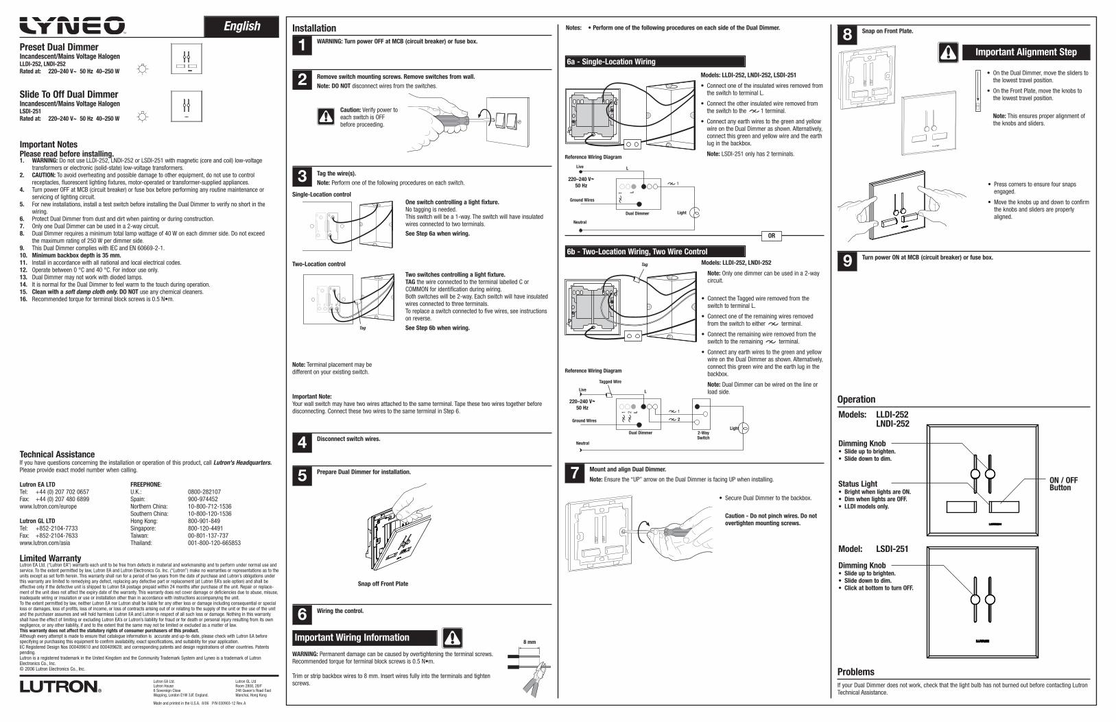
Two switches controlling a light fixture.TAG the wire connected to the terminal labelled C orCOMMON for identification during wiring.Both switches will be 2-way. Each switch will have insulatedwires connected to three terminals.To replace a switch connected to five wires, see instructionson reverse.
See Step 6b when wiring.
English Installation
Technical AssistanceIf you have questions concerning the installation or operation of this product, call Lutron's Headquarters.Please provide exact model number when calling.
Lutron EA LTD FREEPHONE:Tel: +44 (0) 207 702 0657 U.K.: 0800-282107Fax: +44 (0) 207 480 6899 Spain: 900-974452www.lutron.com/europe Northern China: 10-800-712-1536
Southern China: 10-800-120-1536Lutron GL LTD Hong Kong: 800-901-849Tel: +852-2104-7733 Singapore: 800-120-4491Fax: +852-2104-7633 Taiwan: 00-801-137-737www.lutron.com/asia Thailand: 001-800-120-665853
Limited WarrantyLutron EA Ltd. (“Lutron EA”) warrants each unit to be free from defects in material and workmanship and to perform under normal use andservice. To the extent permitted by law, Lutron EA and Lutron Electronics Co. Inc. (“Lutron”) make no warranties or representations as to theunits except as set forth herein. This warranty shall run for a period of two years from the date of purchase and Lutron’s obligations underthis warranty are limited to remedying any defect, replacing any defective part or replacement (at Lutron EA’s sole option) and shall beeffective only if the defective unit is shipped to Lutron EA postage prepaid within 24 months after purchase of the unit. Repair or replace-ment of the unit does not affect the expiry date of the warranty. This warranty does not cover damage or deficiencies due to abuse, misuse,inadequate wiring or insulation or use or installation other than in accordance with instructions accompanying the unit.To the extent permitted by law, neither Lutron EA nor Lutron shall be liable for any other loss or damage including consequential or specialloss or damages, loss of profits, loss of income, or loss of contracts arising out of or relating to the supply of the unit or the use of the unitand the purchaser assumes and will hold harmless Lutron EA and Lutron in respect of all such loss or damage. Nothing in this warrantyshall have the effect of limiting or excluding Lutron EA’s or Lutron’s liability for fraud or for death or personal injury resulting from its ownnegligence, or any other liability, if and to the extent that the same may not be limited or excluded as a matter of law.This warranty does not affect the statutory rights of consumer purchasers of this product.Although every attempt is made to ensure that catalogue information is accurate and up-to-date, please check with Lutron EA beforespecifying or purchasing this equipment to confirm availability, exact specifications, and suitability for your application.EC Registered Design Nos 000409610 and 000409628; and corresponding patents and design registrations of other countries. Patentspending.Lutron is a registered trademark in the United Kingdom and the Community Trademark System and Lyneo is a trademark of LutronElectronics Co., Inc.© 2006 Lutron Electronics Co., Inc.
Important NotesPlease read before installing.1. WARNING: Do not use LLDI-252, LNDI-252 or LSDI-251 with magnetic (core and coil) low-voltage
transformers or electronic (solid-state) low-voltage transformers.2. CAUTION: To avoid overheating and possible damage to other equipment, do not use to control
receptacles, fluorescent lighting fixtures, motor-operated or transformer-supplied appliances.4. Turn power OFF at MCB (circuit breaker) or fuse box before performing any routine maintenance or
servicing of lighting circuit.5. For new installations, install a test switch before installing the Dual Dimmer to verify no short in the
wiring.6. Protect Dual Dimmer from dust and dirt when painting or during construction.7. Only one Dual Dimmer can be used in a 2-way circuit.8. Dual Dimmer requires a minimum total lamp wattage of 40 W on each dimmer side. Do not exceed
the maximum rating of 250 W per dimmer side.9. This Dual Dimmer complies with IEC and EN 60669-2-1.10. Minimum backbox depth is 35 mm.11. Install in accordance with all national and local electrical codes.12. Operate between 0 °C and 40 °C. For indoor use only.13. Dual Dimmer may not work with dioded lamps.14. It is normal for the Dual Dimmer to feel warm to the touch during operation.15. Clean with a soft damp cloth only. DO NOT use any chemical cleaners.16. Recommended torque for terminal block screws is 0.5 N•m.
Preset Dual DimmerIncandescent/Mains Voltage HalogenLLDI-252, LNDI-252Rated at: 220–240 V~ 50 Hz 40–250 W
1 WARNING: Turn power OFF at MCB (circuit breaker) or fuse box.
2 Remove switch mounting screws. Remove switches from wall.Note: DO NOT disconnect wires from the switches.
One switch controlling a light fixture.No tagging is needed.This switch will be a 1-way. The switch will have insulatedwires connected to two terminals.
See Step 6a when wiring.
Tag
3 Tag the wire(s).Note: Perform one of the following procedures on each switch.
Important Note:Your wall switch may have two wires attached to the same terminal. Tape these two wires together beforedisconnecting. Connect these two wires to the same terminal in Step 6.
Single-Location control
Disconnect switch wires.4
5 Prepare Dual Dimmer for installation.
Snap off Front Plate
Important Wiring Information
WARNING: Permanent damage can be caused by overtightening the terminal screws.Recommended torque for terminal block screws is 0.5 N•m.
Trim or strip backbox wires to 8 mm. Insert wires fully into the terminals and tightenscrews.
8 mm
Wiring the control.6
Slide To Off Dual DimmerIncandescent/Mains Voltage HalogenLSDI-251Rated at: 220–240 V~ 50 Hz 40–250 W
Caution: Verify power toeach switch is OFFbefore proceeding.
Turn power ON at MCB (circuit breaker) or fuse box.9
Snap on Front Plate.8
• On the Dual Dimmer, move the sliders tothe lowest travel position.
• On the Front Plate, move the knobs tothe lowest travel position.
Note: This ensures proper alignment ofthe knobs and sliders.
Mount and align Dual Dimmer.7• Secure Dual Dimmer to the backbox.
Caution - Do not pinch wires. Do notovertighten mounting screws.
Models: LLDI-252, LNDI-252, LSDI-251
• Connect one of the insulated wires removed fromthe switch to terminal L.
• Connect the other insulated wire removed fromthe switch to the 1 terminal.
• Connect any earth wires to the green and yellowwire on the Dual Dimmer as shown. Alternatively,connect this green and yellow wire and the earthlug in the backbox.
Note: LSDI-251 only has 2 terminals.
Neutral
Ground Wires
Dual Dimmer
Live
Light
Reference Wiring Diagram
6a - Single-Location Wiring
220–240 V~50 Hz
L
L
1
OR
6b - Two-Location Wiring, Two Wire Control
Note: Ensure the “UP” arrow on the Dual Dimmer is facing UP when installing.
Operation
Important Alignment Step
ON / OFFButton
Dimming Knob• Slide up to brighten.• Slide down to dim.
Status Light• Bright when lights are ON.• Dim when lights are OFF.• LLDI models only.
• Press corners to ensure four snapsengaged.
• Move the knobs up and down to confirmthe knobs and sliders are properlyaligned.
Dimming Knob• Slide up to brighten.• Slide down to dim.• Click at bottom to turn OFF.
Models: LLDI-252LNDI-252
Model: LSDI-251
If your Dual Dimmer does not work, check that the light bulb has not burned out before contacting LutronTechnical Assistance.
Problems
Notes: • Perform one of the following procedures on each side of the Dual Dimmer.
Made and printed in the U.S.A. 8/06 P/N 030903-12 Rev. A
Lutron EA Ltd.Lutron House6 Sovereign CloseWapping, London E1W 3JF, England.
Lutron GL LtdRoom 2808, 28/F248 Queen's Road EastWanchai, Hong Kong
C
1
C
1
Note: Terminal placement may bedifferent on your existing switch.
Tag
Reference Wiring Diagram
220–240 V~50 Hz
Neutral
Ground Wires
Dual Dimmer 2-WaySwitch
Live
Light
L
L 11 2
2
Tagged Wire
1
Models: LLDI-252, LNDI-252
Note: Only one dimmer can be used in a 2-waycircuit.
• Connect the Tagged wire removed from theswitch to terminal L.
• Connect one of the remaining wires removedfrom the switch to either terminal.
• Connect the remaining wire removed from theswitch to the remaining terminal.
• Connect any earth wires to the green and yellowwire on the Dual Dimmer as shown. Alternatively,connect this green wire and the earth lug in thebackbox.
Note: Dual Dimmer can be wired on the line orload side.