说明书0304 revised - lowes holiday
TRANSCRIPT

TGC3001&TGC3601
-DO NOT store or use gasoline or other flammable vapors and liquids in the vicinity of this or any other appliance.
-WHAT TO DO IF YOU SMELL GAS:·DO NOT try to light any appliance.·DO NOT touch any electrical switch.·DO NOT use any phone in your building.·Immediately call your gas supplier from a neighbor's phone. Follow the gas
supplier's instructions.·If you cannot reach your gas supplier, call the fire department.
-Installation and service must be performed by a qualified
installer, service agency, or the gas supplier.
WARNING: If the information in this manual is not fol lowed exactly,a f ire
or explosion may result causing property damage, personal injury, or death.
Contents
Important safety information
Overview
Dimension and clearance
Circuit Diagram
Side &Back Panel Layout
What's included
Electrical Requirements
Using the cooktop burners
Ignition
Cookware
Install the grates
Wok Ring
Care and cleaning of the cooktop
Cooktop surface
Stainless steel surfaces
Control knobs
Burner grates and components
Burner caps and heads
Burner bases
Electrodes
Grates and wok ring
Burner head and cap replacement
Burner cap
Troubleshooting
Checkpoints
Gas Cooktop Conversion
Warranty
3
10
10
12
13
14
15
15
15
17
17
18
18
18
19
19
20
20
21
21
21
22
23
24
24
25
29
-1- -2-

-3- -4-
Important safety information Read all instructions before using this appliance
·All electrical and gas equipment with moving parts can be
be followed to minimize the risk of injury, death, or property
damage.
dangerous. Please read the important safety instructions
for this appliance in this manual. The instructions must
·Save this manual. Please Do Not Discard.
Symbols used in this manual
WARNING
Hazards or unsafe practices that may result in severe
personal injury or death.
CAUTION
Hazards or unsafe practices that may result in electric
shock, personal injury, or property damage.
NOTE
Useful tips and instructions
!
!
These warning icons and symbols are here to prevent
injury to you and others. Please follow them explicitly.
After reading this section, keep it in a safe place for
future reference.
State of California Proposition 65 warning (US only)
Commonwealth of Massachusetts
WARNING
This product contains chemicals known to the State of
California to cause cancer and birth defects or other
reproductive harm.
Gas appliances can cause low-level exposure to Proposition
65 listed substances, including but not limited to, benzene,
carbon monoxide, formaldehyde and soot,substances
resulting from the incomplete combustion of natural gas or LP
fuels.For more information go to www.P65 warnings.ca.gov
!
·This product must be installed by a licensed plumber or gas
fitter qualified or licensed by the State of Massachusetts.
When using ball-type gas shut-off valves,you must use the
T-handle type. Multiple flexible gas lines must not be
connected in series.
General safety
WARNING!To reduce the risk of fire, electric shock, personal injuries, and/or death, observe the following precautions.
·Do not touch any part of the cooktop, including but not limited to cooktop burners during or immediately after cooking.
·Know the location of the gas shut-off valve and how to shut it off.
·Make sure the hold down brackets are properly installed on the cooktop. See the installation instructions for more information.
·Do not let children near the cooktop. Do not let children go onto the cooktop. Do not let children play with the cooktop or any
part(s) of the cooktop. Do not leave children unattended in an area where the cooktop is in use.
·Remove all packaging materials from the cooktop before operating to prevent ignition of these materials. Keep all packaging
materials out of children's reach.Properly dispose the packaging materials after the cooktop is unpacked.
·Do not store any object of interest to children on the cooktop or back-guard of the cooktop. Children climbing on the cooktop to
reach items could be killed or seriously injured.
·Do not operate the cooktop if the cooktop or any part of the cooktop is damaged, malfunctioning, or missing parts.
·Do not use the cooktop as a space heater. Use the cooktop for cooking only.
Use only dry pot holders.
·Do not use the cooktop to heat unopened food containers.
·Unplug or disconnect the power cord before servicing.
·Never store combustible materials (dishtowels, paper products, etc.) or packaged or canned food under the cooktop in a way that
would let them come in contact with the underside of the cooktop. The combustible material could catch fire and the packaged or
canned food could explode.
·Make sure the gas line is not compressed or bent by heavy objects. Otherwise, gas leaks or incomplete combustion may occur.

-6-
Fire safety Gas safety
WARNING! WARNING!To reduce the risk of fire, electric shock, personal injuries,
and/or death, observe the following precautions.
To reduce the risk of fire, electric shock, personal injuries,
and/or death, observe the following precautions.
·Leak testing of the appliance must be conducted according
to the manufacturer's instructions. Do not use a flame to check
for gas leaks. Use a brush to spread a soapy water mixture
around the area you are checking. If there is a gas leak, you
will see small bubbles in the soapy water mixture at the leak
point.
Checking for gas leaks
If you smell gas:
Electrical and grounding safety
WARNING!To reduce the risk of fire, electric shock, personal injuries, and/or death, observe the following precautions.
·Plug the power cord into a grounded 3-prong outlet.
·Do not remove the grounding prong.
·Do not use an adapter or an extension cord.
·Do not use a damaged power plug, power cord, or loose power outlet.
·Do not modify the power plug, power cord, or power outlet in any way.
·Do not put a fuse in a neutral or ground circuit.
·Use a dedicated 120-volt, 60-Hz, 20-amp, AC, fused electrical circuit for this cooktop. A time-delay fuse or circuit breaker is recommended.
Do not plug more than one appliance into this circuit.
·Do not connect the ground wire to plastic plumbing lines, gas lines, or hot water pipes.
·This cooktop must be Earth grounded. In the event of a malfunction or breakdown, grounding will reduce the risk of electrical shock by
providing a path for the electric current. This cooktop is equipped with a cord having a grounding plug. The plug must be firmly plugged into an
outlet that is properly installed and grounded in accordance with the local codes and ordinances. If you are unsure whether your electrical outlet
is properly grounded, have it checked by a licensed electrician.
·The cooktop is supplied with a 3-pronged grounded plug. This cord must be plugged into a matching, grounded 3-prong outlet that meets all
local codes and ordinances. If codes permit the use of a separate ground wire, we recommend that a qualified electrician determine the proper
path for this ground wire.
·Electrical service to the cooktop must conform to local codes. Barring local codes,it should meet the latest ANSI/NFPA No. 70 – Latest Revision
(for theU.S.) or the Canadian Electrical Code CSA C22.1 – Latest Revisions.
·It is the personal responsibility of the cooktop owner to provide the correct electrical service for this cooktop.
-5-
·Do not store, place, or use flammable or combustible
materials such as paper,plastic, pot holders, linens
curtains, gasoline or other flammable vapors or liquids
near the cooktop.
·Do not wear loose fitting or hanging garments while
using the cooktop.
·To avoid grease buildup, regularly clean the vents.
·Do not let pot holders or other flammable materials touch
a heating element. Do not use a towel or other bulky items
made out of cloth in place of a pot holder.
·Do not use water on a grease fire. To put out a grease
fire, turn off the heat source and smother the fire with a
tight-fitting lid or use a multipurpose dry chemical or foam-
type fire extinguisher.
·Do not heat unopened food containers. The buildup of
pressure may cause the container to burst and result in
injury.
·Always check if the burners are combusting normally.
Overheating may cause a fire, and incomplete combustion
may cause carbon-monoxide poisoning.
·Close the valve and do not use the cooktop. ·Do not light a match, candle, or cigarette. ·Do not turn on any gas or electric appliances. ·Do not touch any electrical switches or plug a power cord
into an outlet. ·Do not use any phone in your building. ·Evacuate the room, building, or area of all occupants. ·Immediately call your gas supplier from a neighbor's
phone. Follow the gas supplier's instructions. ·If you cannot reach your gas supplier, call the fire
department.

-7- -8-
Installation safety
WARNING!To reduce the risk of fire, electric shock, personal injuries, and/or death, observe the following precautions.
·Have your cooktop installed and properly grounded by a qualified installer, in accordance with the installation instructions. Any adjustment
and service should be performed only by qualified gas cooktop installers or service technicians.
·Do not attempt to service, modify, or replace your cooktop or any part of your cooktop unless it is specifically recommended in this manual.
All other service should be referred to a qualified technician.
·Always use new flexible connectors when installing a gas appliance. Do not use old flexible connectors.
·Make sure the hold down brackets are properly installed on the cooktop. See the installation instructions for more information.
·Remove all tape and packaging materials.
·Remove all accessories from the cooktop, Grates and griddles are heavy. Use caution when handling them.
·Make sure no parts came loose during shipping.
·Make sure your cooktop is correctly installed and adjusted by a qualified service technician or installer for the type of gas (natural or LP) you
will use. For your cooktop to utilize LP gas, the installer must replace the 4 or 6 surface burner orifices with the provided LP orifice set,
and reverse the GPR adapter. Further more the bypass in burner valve will need to be adjusted.These adjustments must be made by a qualified
service technician in accordance with the manufacturer's instructions and all codes and requirements of the authority having jurisdiction.
The qualified agency performing this work assumes the gas conversion responsibility.
·Installation of this cooktop must conform with local codes or, in the absence of local codes, with the National Fuel Gas Code,
ANSI Z223.1/NFPA.54, latest edition. In Canada, installation must conform with the current Natural Gas Installation Code, CAN/CGA-B149.1,
or the current Propane Installation Code, CAN/CGA-B149.2, and with local codes where applicable. This cooktop has been design-certified
by ETL according to ANSI Z21.1, latest edition, and Canadian Gas Association according to CAN/CGA-1.1, latest edition.
·Make sure the middle valve has adequate capacity and is not clogged.
·This cooktop must be installed by a qualified technician. Otherwise, gas leaks, fire, or defective ignition may occur.
Location safety
WARNING!
To reduce the risk of fire, electric shock, personal injuries,
and/or death, observe the following precautions.
·This cooktop is for indoor, household use only. Do not install
the cooktop in areas exposed to the weather and/or water.
·Do not install the cooktop in a place which is exposed to a strong
draft.
·Select a location where a grounded, 3- prong outlet is easily
accessible.
·If the cooktop is located near a window, do not hang long
curtains or paper blinds on that window.
·For the cooktop to ventilate properly, there must be enough
clearance at the top, back and sides of the cooktop, and underneath
the cooktop. The vents allow the necessary exhaust for the cooktop
to operate properly with correct combustion.
·Make sure the wall coverings around the cooktop can withstand
heat up to 194 °F (90 °C).
·Cabinet storage above the surface of the cooktop should be avoided.
If cabinet storage above the cooktop is necessary: allow a minimum
clearance of 30 inches (76.2 cm) between the cooking surface and
the bottom of the cabinets.
Cooktop safety
WARNING!To reduce the risk of fire, electric shock, personal injuries,
and/or death, observe the following precautions.
· Select cookware that is designed for range top cooking. Use cookware
that is large enough to cover the burner grates. Adjust the burner flames
so that the flames do not extend beyond the bottom of the cookware.
·M ake sure all burners are off when not in use.
·D o not use aluminium foil to line the grates or any part of the cooktop.
·D o not leave burners unattended on medium or high heat settings.
·B efore igniting, make sure all burner caps are properly in place and
all burners are level.
·A lways use the LITE position when igniting the burners and make sure
the burners have ignited. If ignition fails, turn the knob to OFF and wait
until the gas has dissipated.
·W hen you set a burner to simmer, do not turn the knob quickly.
Make sure the flame stays on.
·D o not place any objects other than cookware on the cooktop.
·T his cooktop is designed to cook with a wok or wok ring attachment.
If foods are flamed, they should only be flamed under a ventilation
hood that is on.

·Before removing or changing cookware, turn off the burners.
·Remove food and cookware immediately after cooking.
·Before removing any parts of the burner for cleaning, make sure the cooktop is off and completely cool.
·After cleaning the burner spreader, make sure it is completely dry before re-assembling.
·To avoid carbon monoxide poisoning, do not pour water into the cooktop well while cleaning.
·To avoid cookware discoloration, deformity, and/or carbon monoxide poisoning, do not use cookware that is substantially larger than the grate.
·Make sure cookware handles are turned to the side or rear of the cooktop and not over other surface burners.
·Stand away from the cooktop while frying.
·Always heat frying oils slowly, and watch as they heat. If you are frying foods at high heat, carefully watch during the cooking process. If a
combination of fats or oils is to be used during frying, mix them together before heating.
·Use a deep-fryer thermometer whenever possible. This prevents overheating the fryer beyond the smoking point.
·Use a minimum amount of oil when shallow pan-frying or deep-frying. Avoid cooking unthawed food or food with excessive amounts of ice.
·Before moving cookware full of fats or oils, make sure it has completely cooled.
·To prevent delayed eruptive boiling, always allow heated liquids to stand at least 20 seconds after you have turned off the burner so that the
temperature in the liquid can stabilize. In the event of scalding, follow these first aid instructions:
1. Immerse the scalded area in cool or lukewarm water for at least 10 minutes.
2. Do not apply any creams, oils, or lotions.
3. Cover with a clean, dry cloth.
·If a power failure occurs or the electric ignition fails to operate, do not use matches or lighters to ignite the burners. This may cause a fire or
physical burns.
·Do not place and use electric-powered cooking devices such as IH rice cookers or desktop cooking heaters on top of your cooktop. Electromagnetic
forces from these appliances may cause the cooktop to malfunction.
OverviewDimension and clearance
30" /36”Model:TGC3001/TGC3601
TGC3001
Left Front NG/LP : 18000 BTU/H
Right Front NG/LP : 9000 BTU/H
Right Rear NG/LP : 9000 BTU/H
Left Rear NG/LP : 12000 BTU/H
TGC3601
Center Front NG/LP : 18000 BTU/H
Left Front NG/LP : 18000 BTU/H
Left Rear NG/LP : 12000 BTU/H
Center Rear NG/LP : 12000 BTU/H
Right Front NG/LP : 6000 BTU/H
Right Rear NG/LP : 6000 BTU/H
-9- -10-
-12--11-
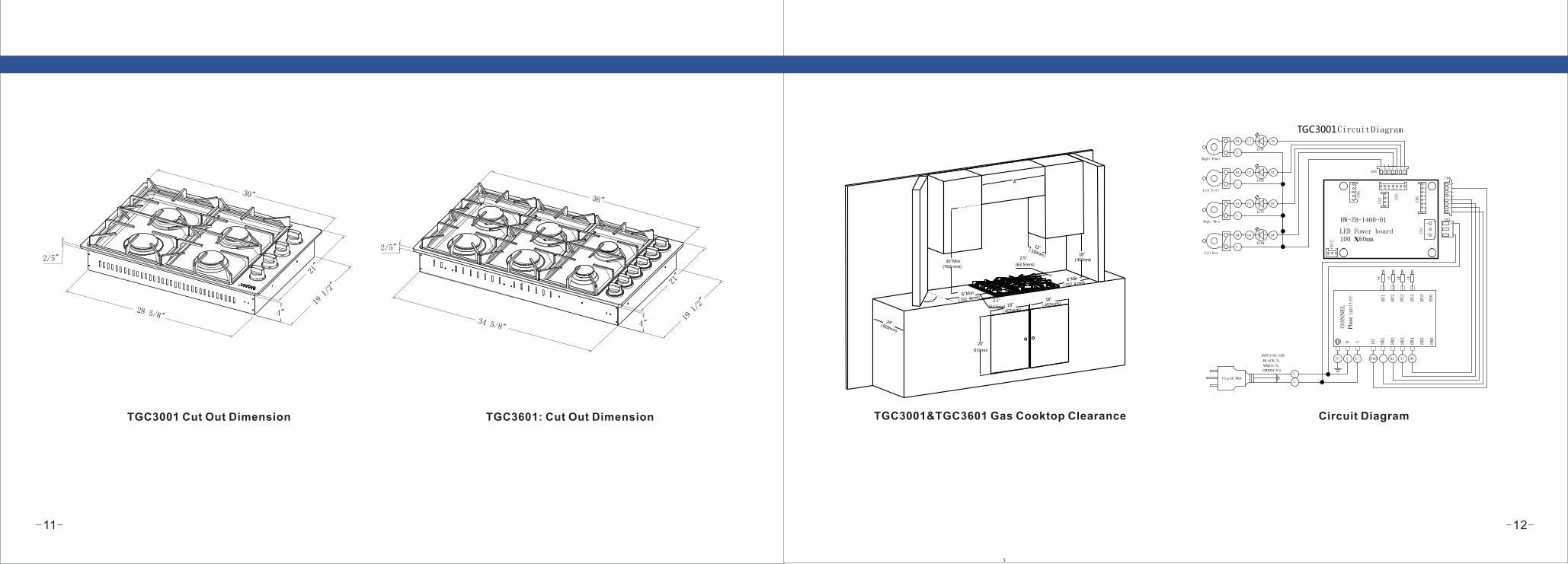
TGC3001&TGC3601 Gas Cooktop Clearance Circuit DiagramTGC3001 Cut Out Dimension TGC3601: Cut Out Dimension
TGC3001Circuit Diagram
1234567
CN5
12
CN1
12
23
1
12
34
12
34
56
78
1234567
21
CN12
CN4
CN7 CN5
CN6
CN1
LED Power board 100 X 60mm
HW-ZB-1460-01
D1
N LPE COS1 S2 S3 S4
LF
12
34
56
78
CN6
Plug AC Male
WHITE(N)
BLACK(L)
GREEN(PE)
INPUT:AC 120V
L
N
N L SW1
SW2
SW3
SW4
SW5
SW6
HV1
HV2
HV3
HV4
HV5
HV6
CHAN
NE
L
CO
Plu
se ignit
er
Left Rear
LED4
K4
G
Right Rear
LED3
K3
G
Left Front
LED5
K2
G
Right Front
LED1
K1
G
LRRF RR
D2
D3
D4
G 1
G2
G3
G4
30"Min
(762 mm)
18"
( 457m m )
18"
( 457m m )
18"
( 457m m )
13"( 330m m )
24" 610mm
24"( 610mm)
6"M i n
( 152. 4m m )
6"M i n
( 152. 4 m m )
2.5"
(63.5mm)
A
2.5"
(63.5mm)
1
30"
21"
4"
19 1/2"
28 5/8"
2/5"
36"
21"
19 1/2"
2/5"
34 5/8" 4"

-13- -14-
TGC3001&TGC3601 Side &Back Panel Layout
Each burner has a corresponding knob that lets you to set the flame level from LO to HI. In addition, each burner knob
has a Lite setting. Turning a knob to Lite ignites the corresponding burner. The burner indicators are located above
each knob and show which burner the knob controls. Each burner is designed for specific cooking purposesA
statement of the maximum gas(NG10in w.c/LP 14in w.c) supply pressure in accordance with the inlet pressure rating
of the gas appliance pressure regulator supplied.
TGC3001&TGC3601 Wok ring (1)
What’s included
TGC3001 Surface burner grates (2)
TGC3601 Surface burner grates (3)
TGC3001 Surface burners and caps (4)
TGC3601 Surface burners and caps (6)
TGC3601Circuit Diagram
1234567
CN5
12
CN1
12
23
1
12
34
12
34
56
78
1234567
21
CN12
CN4
CN7 CN5
CN6
CN1
LED Power board 100 X 60mm
HW-ZB-1460-01
Left Rear
LED1
D1
K6
G
N LPE COS1 S2 S3 S4
LFCF
12
34
56
78
CN6
Plug AC Male
WHITE(N)
BLACK(L)
GREEN(PE)
INPUT:AC 120V
L
N
N L SW1
SW2
SW3
SW4
SW5
SW6
HV1
HV2
HV3
HV4
HV5
HV6
CHAN
NE
L
CO
Plu
se igniter
Middle Rear
LED2
K5
G
Right Rear
LED3
K4
G
Left Front
LED4
K3
G
Middle Front
LED5
K2
G
Right Front
LED6
K1
G
RF
S5 S6
LRCRRR
D2
D3
D4
D 5
D6
G1
G2
G3
G4
G5
G6

-16--15-
ELECTRICAL REQUIREMENTS
Thor Kitchen Gas cooktop requires 110 volts, 50/60 Hz electrical supply to operate the ignition system.
WARNING!
Electrical Grounding InstructionsThis appliance is equipped
with a (three-prong)(four-prong) grounding plug for your
protection against shock hazard and should be plugged directly
into a properly grounded receptacle. Do not cut or remove the
grounding prong from this plug.
Using the cooktop burners
Ignition
The knob LED indicates if a burner knob has been turned on.It
does not indicate if the burner flame is on.Check for an actual
flame, whether the knob LED is on or off.Make sure all cooktop
burners are properly installed. A statement of the gas supply
pressure for checking the regulator setting[The pressure stated
shall be at least NG 5in w.c/LP 10in w.c above the manufacturer’s
specified manifold pressure.]
! CAUTION
To light a burner:
1.Your cooktop equip with an automatic ignition system and
then turn anticlockwise to the ignite position,push in the control
knob,the knob LED turns on and you will hear a “clicking” sound
indicating the electronic ignition system is working properly.2.After the cooktop burner lights, turn the control knob to shift it
out of the Lite position and turn off the electronic ignition
system.3.Turn the control knob to adjust the flame Level.
Manual ignition
Flame level
WARNING!
WARNING!
If there is a power failure, you can ignite the burner manually.
Use caution when doing this.
1.Hold a long gas grill lighter to the cooktop burner you want to
light.
2.Push in the control knob for that burner, and then turn it to the
Lite position. Turn on the grill lighter to ignite the burner.
3.After the burner is lit, turn the control knob to adjust the flame
level.
The flames on the burners should always stay under the cookware,
and should not extend beyond the cookware bottom at any time.
·Flames larger than the cookware bottom may result in a fire or
physical injury.
·After turning on a surface burner, make sure that the burner has
ignited even if the knob LED is on. Adjust the level of the flame by
turning the burner knob.
·Always turn off the surface burner controls before removing cookware.
All surface burner controls should be turned OFF when you are not
cooking.
·Always turn the burners off before you go to sleep or go out.
·If you smell gas, turn off the gas to the cooktop and call a qualified
service technician. NEVER use an open flame to locate a leak.
·If the LED on the control knob doesn't go on when the surface burner
has ignited,please call Thorkitchen customer service.
·If the knob LED illuminates, but the surface burner does not ignite,
turn off the control knob immediately.
·Do not operate the burner for an extended period of time without
cookware on the grate. The finish on the grate may chip without
cookware to absorb the heat.
·Be sure the burners and grates are cool before you place your hand,
a pot holder, cleaning cloths or other materials on them.
NEVER use this appliance as a space heater to heat or warm the room.
Doing so may result in carbon monoxide poisoning and overheating
of the oven.

-17- -18-
Cookware
Requirements
Size limitations
! CAUTION
Wok Ring Care and cleaning of the cooktop
WARNING!
Be sure electrical power is off and all surfaces are cool before
cleaning any part of the cooktop.
·Flat bottom and straight sides
·Tight-fitting lid
·Well-balanced with the handle weighing less than the main
portion of the pot or pan.
·Do not place a pan or pot with a bottom diameter of about
10 inches or more on the Left Front or Right Front burner.
·Always make sure cookware handles are turned to the side
or rear of the
·cooktop and not over other surface burners. This will
minimize the chance of burns,spillovers, and the ignition of
flammable materials that can occur if pots or pans are
bumped accidently.
·If using glass cookware, make sure it is designed for
cooktop cooking.
·Never leave plastic items on the cooktop. They can melt or
ignite. Heating a sealed plastic container can cause
a building up of dangerous pressure which can cause the
container to explode.
·When use a wok ,make sure you hold the handle of a wok
or a small one-handled pot while cooking.
Woks are often used for stir frying, pan frying, deep frying,
and poaching. The provided wok ring supports 12” to 14” woks
1. Turn off all burners, and wait until the grates completely
cool down.
2. Place the wok ring on any grate.
3. Put a wok on the wok ring. Make sure the wok settles
well.
4. Turn on the burner, and adjust the flame level as
appropriate.
! CAUTION
·Do not remove the wok ring until the cooktop grates,
surfaces, and wok grate completely cool down.
·When you use the wok with the cooktop or when the oven
is on, the wok ring on the cooktop may become very hot.
Use oven gloves when placing or removing the wok ring.
·Do not use pans with a flat bottom or woks with a diameter
less than the wok ring diameter. The pan or wok may tip
over.
·Do not use an oversized pan. The burner flames may
spread out, causing damage nearby.
·This cooktop is not designed to flame foods. If foods are
flamed, they should only be flamed under a ventilation
hood that is on.
Cooktop surface
We recommend that you remove food spills immediately after they
take place.
1. Turn off all surface burners.
2. Wait until all burner grates cool down, and then remove them.
3. Clean the cooktop surface using a soft cloth. If food spills run into
gaps of the burner components, remove the burner cap and the
head,and wipe up the spills.
4. When you are done cleaning, reinsert the burner components,
and then put the burner grates back into position.
1. Locate the notch on the back of the right grate.
2. Orient the right grate so that it is on the right side of
the cooktop with the notch in the back.
3. Gently lower the legs of the right grate into the
corresponding dimples on the cooktop.
4. Gently lower the legs of the remaining two grates into
the corresponding dimples on the cooktop as shown
in the illustration
Install the grates
Install the grates as instructed below for longest life.
When installed properly, the openings in the grates are
centered over the burners.
The three cooktop grates are designed to fit in specific
positions on the cooktop. For maximum stability,
these grates should only be used in their proper positions.
The back of the right grate is notched to help you orient
the grates correctly. See the illustration below.
To replace the grates correctly, follow these steps:

-20--19-
Stainless steel surfaces
! CAUTION
Control knobs
Make sure all surface burner knobs are in OFF position.
Burner grates and components Burner caps and heads
NOTE
! CAUTION
1. Do not remove any spills, spots, and grease stains using
a soft, wet cloth until surface is cool.
2. Apply an approved stainless steel cleanser to a cloth or
paper towel.
3. Clean one small area at a time, rubbing with the grain of
the stainless steel if applicable.
4. when done, dry the surface using a soft, dry cloth.
5. Repeat steps 2 through 4 as many times as necessary.
·Do not use a steel-wool pad or abrasive cleaner, which
can scratch or damage the surface.
·Do not remove the cooktop surface to clean it. The gas
lines leading to the burner manifolds can be damaged,
resulting in a fire or system failure.
·Do not pour water into the cooktop well while cleaning
the cooktop. This could leak down into the cooktop gas
and electrical systems creating a risk of electrical shock or
high levels of Carbon Monoxide due to corrosion of the gas
valves or ports.
·Do not spray any type of cleanser into the manifold holes.
The ignition system is located in those holes and must be
kept free of moisture.
1. Grasp each knob and pull straight up to remove
2. Clean the knobs with soft cloth and warm, soapy water.
Then rinse and dry them thoroughly.
3. Clean the stainless steel surfaces using stainless steel
cleaner.
4. Re-attach the knobs in the OFF position to the control
valve stems.
5. Do not remove spill protector.
Do not clean the control knobs in a dishwasher.
Do not spray cleansers directly onto the control panel.
Moisture entering the electric circuits may cause electric
shock or product damage.
01 Grasp each knob and pull straight up to remove.
02 Spill protector. Do not remove
Turn off all surface burners and make sure they have
all cooled down.
1. Remove the burner grates.
2. Remove the burner caps from the burner heads.
3. Remove the burner heads from the valve manifolds to reveal the
starter electrodes.
4. Clean all removable grates and burner components in warm,
soapy water. Do not use steel-wool pads or abrasive cleaners.
5. Rinse and dry grates and burner components thoroughly.
6. Return the burner heads to their positions on top of the manifold
valves. Make sure a starter electrode is inserted through the hole in
each burner head burner component re-assembly instructions.
7. Return the burner caps to their positions on top of the burner
heads. To ensureproper and safe operation, make sure the burner
caps lie flat on top of the burner heads.
8. Re-install the burner grates in their respective positions.
9. Turn on each burner and check if it operates properly.After
verifying that a burner operates normally, turn it off.
Before removing the burner caps and heads, remember their size
and location. Replace them in the same location after cleaning.
Wash burner caps and burner heads in hot, soapy water and rinse
with clean running water. You may scour with a plastic scouring pad
to remove burned-on food particles.
Use a sewing needle or twist tie to unclog the small holes in the
burner head, if required.
·Do not wash any burner parts in a dishwasher.
·Do not use steel wool or scouring powders to clean the burners

-21-
Burner bases
! CAUTION
The burner bases cannot be removed for cleaning. Make sure
that no water gets into the burner bases and the brass gas
orifices. Wipe clean with a damp cloth. Be careful not to scratch,
deform, or damage the bases. Allow them to dry fully before using.
Electrodes
Do not attempt to remove the electrode from the cooktop or
burner bases.Be careful not to push in any cooktop controls
while cleaning the cooktop. A slight electrical shock might
result which could cause you to knock over hot cookware.
Make sure that the white ceramic electrodes in the cooktop
are clear of soil and dry.Clean the metal part of the electrode
with a soft cloth. Do not use water to clean the igniters. Before
reassembling the surface burners,push down gently on each of
the white ceramic, electrodes to make sure they are pressed
against the burners bases.
NOTE
Do not attempt to remove the electrode from the cooktop.
Grates and wok ring
Do not clean the grates or wok ring in a dishwasher. They will be
damaged. Lift grates out when cool. Grates should be washed regularly
and after spillovers. Wash them in hot, soapy water and rinse with clean
water. When replacing the grates, be sure they are positioned securely
over the burners.
Burner head and cap replacement
1. Orient the burner head so that the
opening for the electrode lines up
with the electrode.
2. Install the burner head so that the
electrode passes through the
opening for the electrode.
Make sure the burner head lies flat
on the stove top
1. Match the burner caps to the burners by size,
and then re-install the caps on the burner heads.
Make sure each cap is re-installed on the
correct burner head, is centered on the burner
head, and lies flat.
Round Burner head
Make sure all burner components
(heads and caps) are re-installed
properly. They will be stable and
rest flat when correctly installed.
! CAUTION
Burner cap
! CAUTION
! CAUTION
Make sure all burner components (heads and
caps) are re-installed properly. They will be stable
and rest flat when correctly Installed
After installation of surface burners, check the
ignition.
Incorrect placement of a burner head or cap
will result in poor ignition or uneven flames
(as shown in the pictures).
Burner cap
Burner Head
-22-

Troubleshooting
If you encounter a problem with the cooktop, check the tables starting
below, and then try the suggested actions.
Checkpoints
Gas safety
Gas Cooktop Conversion
The cooktop is set for use with Natural Gas (NG).The factory setting
is indicated on the serial plate.When set for Natural Gas(NG) operation,
the pressure regulator will regulate the gas to 4” inches water column
pressure.When set for Liquefied Propane Gas(LPG)operation,the
pressure regulator will regulate the pressure to 11”inches water column.
Please refer to Instructions for Converting cooktop to Operate on
Liquefied Petroleum Gas.
NG to LPG Conversion
Convertible Pressure Regulator
The cooktops are shipped to operate on Natural Gas (NG). Save
the NG orifices removed from the appliance for future use,make
sure you note which orifices are for which burner if you plan on
converting back to NG.
Instructions for Converting cooktop to Operate on Liquefied
Petroleum Gas
INSTALLATION AND SERVICES MUST BE PERFORMED
BY A QUALIFIED INSTALLER
IMPORTANT: SAVE INSTRUCTION MANUAL FOR THE LOCAL
INSPECTOR'S USE. READ AND SAVE THESE INSTRUCTIONS
FOR FUTURE REFERENCE
Determine the combination of top burners that are featured on your
cooktop. Identify the parts you need from this kit to complete the L.P.
conversion. When burners are converted from natural to L.P. the BTU
ratings are as follows: Note: For operation at elevations above 2000ft.,
appliance rating shall be reduced at the rate of 4% for each 1000 ft.
above sea level.
WARNING! This conversion kit must be installed by a qualified service technician in accordance
with the manufacturer's instructions and all applicable codes and requirements of the authority having
jurisdiction. Failure to follow instructions may result in fire, explosion or production of carbon monoxide
causing property damage, personal injury or loss of life. The qualified service agency is responsible
for the proper installation of this kit. The installation is not proper and complete until the operation of
the converted appliance is checked as specified in the manufacturer's instructions supplied with this kit.
WARNING! Before proceeding with the conversion, shut off the gas supply before disconnecting
electrical power to the range. Be sure power supplies are off before installing the conversion kit.
Failure to do so could cause serious bodily injury.
The surface burner knob is not in the OFF position and the burner is not lit.
Turn the burner knob to OFF.
There is a gas leak. Clear the room, building, or area of all occupants.Immediately call your gas supplier from a neighbor’s phone. Do not call from your phone. It is electrical and could cause a spark that could ignite the gas. Follow the gas supplier ’s instructions.If you cannot reach your gas supplier, call the fire department.
Problem Possible cause Action
The control knob is not set properly. Push in the control knob and turn it to the Lite position.
The burner caps are not in place.The burner base is misaligned.
Clean the electrodes. Put the burner cap on the burner head.Align the burner base.
The control knob has been left in the Lite position.
After the burner lights, turn the control knob to a desired setting.If the burner still clicks, contact a service technician.
The wrong burner orifice is installed. Check the burner orifice size. Contact your installer if you have the wrong orifice (LP gas instead of natural gas or natural gas instead of LP gas).
You smell gas.
A surface burner clicks during operation.
Very large or yellow surface burner flames.
Surface burners do not light.
NG 2.10mm 1.60 mm 1.26 mm 1.26 mmLPG 1.24mm 1.00 mm 0.84 mm 0.84 mm
NG 2.10 mm 1.60 mm 1.10 mm 1.10 mm 2.10 mm 1.60 mmLPG 1.24 mm 1.00 mm 0.75 mm 0.75 mm 1.24 mm 1.00 mm
TGC3601 Left Front Left Rear Right Front Right Rear Center Front Center Rear
-24--23-

-25- -26-
Left Front
Right Front
Right Rear
Left Rear
TGC3001 BURNER PERFORMANCE
Total number of cooktop Burners 4Burners
18000 BTU/H
12000 BTU/H
9000 BTU/H
9000 BTU/H
TGC3601 BURNER PERFORMANCE
Total number of cooktop Burners 6Burners
Center Front
Left Front
Left Rear
Center Rear
Right Front
Right Rear
18000 BTU/H
12000 BTU/H
18000 BTU/H
12000 BTU/H
6000 BTU/H
6000 BTU/H
IMPORTANT: After replacing the natural gas to LP orifices, be sure to
keep the original factory installed natural gas orifices for future range
conversion
back to natural gas.
Tools for LP Conversion
7mm Tool – Top Burner Orifice Replacement
Flat Screw Driver ¢2.0*130 (Not Available with the LP Conversion Kit
Package)
– Bypass Adjustment Adjustable
Wrench *2 (Not Available with the LP Conversion Kit Package) – Orifice
Adjustment
TGC3001&TGC3601 LP Conversion
1.Convert the Pressure Regulator
For 30 or 36-inch Cooktop, you could find your regulator on the back left of
the cooktop's back panel.
**IMPORTANT** Pay attention that the NG and LP are in different
direction. All the cooktop are initially designed with NG position, please
have it changed in to LP position.
2.Convert Burner for LP/ Propane Gas
Save the natural gas orifices removed from the appliance for possible
future conversions to natural gas. You should rely on the following
process when converting unit back to Nature gas. Take extra care
when handling orifice parts, making sure the orifice is not
a. Remove top grates, burner caps and inner burner rings.
b. Lift off outer burner heads and burner bases.
c. Remove the factory installed natural gas orifices from the center
of the orifice holders using a 7mm nut driver Remember to keep
the original natural gas orifices for future conversions back to
natural gas.
“IMPORTANT”to identify their markings.
c.1. Replace the 18000BTU burner orifice in each with orifice size 1.24 mm.
c.2 Replace the 12000BTU burner orifice in each with orifice size 1.00 mm.
Please remember not to over tighten the orifice and keep the orifice clean.
c.3 Replace the 9000BTU burner orifice in each with orifice size 0.84 mm.
Please remember not to over tighten the orifice and keep the orifice clean.
c.4 Replace the 6000BTU burner orifice in each with orifice size 0.75 mm.
Please remember not to over tighten the orifice and keep the orifice clean.
Put the burner flame ring back to the main burner bases. Put back the inner
burner rings, burner caps and grates.

-28--27-
3.Convert Burner Valves for LP/Propane Gas
One 5/64” flat screw driver is needed for the Bypass Adjustment on Burner Valve .
a. Please take off the burner knobs to get access to the burner valve part. There's a hole located at bottom right of the burner valve, providing access to
the adjustment of burner valve bypass orifice. Take out the bezel if needed. The hole is part of the micro-switch (the black part) sticking to the burner valve.
Use the screw driver to go across the micro-switch and reach the bypass orifice on the burner valve. Bypass orifice could help to control the flame.
b. Put the knob back, adjust the flame by rotating the knob. The original location of bypass is for NG. If converted to LP, the bypass needs to be screwed in
(in clockwise direction) to tightest position.
Originally, the Bypass is located at NG Position and it's not screwed to the bottom (tightest)
For LP conversion of bypass, not bypass orifice needs to be changed. Screw the Bypass Orifice to bottom (clockwise).
c. Save the main bypass jets, in the plastic bag labeled main jets . When you are using your top burners, if the flame needs to be adjusted accordingly to
fit your need, please adjust the bypass orifices on the burner valve. Put back the knob on and adjust the flame by rotating the bypass via a small flat
screw driver. Check the flame's condition to get the best performance.
4. Reconnect Gas and Electrical Supply to Cooktop.
Leak testing of the appliance shall be conducted according to the
installation instructions provided with the cooktop. Checking for
Manifold Gas Pressure . If it is necessary to check the manifold
gas pressure, remove the burner cap, inner ring, outer burner
head and burner base of the right front top burner and connect a
manometer (water gauge) or another pressure test device to the
burner orifice. Use a rubber hose with inside diameter of
approximately ¼” and hold the end of the tube tight over the orifice.
Turn the gas valve on. For a more accurate pressure check,
have at least two other top burners burning. Be sure that the gas
supply (inlet) pressure is at least one inch above the specified
manifold pressure. The gas supply pressure should never be
over 14” water column. When properly adjusted the manifold water
column pressure is 10” for LP/Propane gas or 5” for Natural Gas.
5. Installation of New LP / Propane Rating / Serial Plate
Record the model and serial number on the LP / Propane Rating
serial plate provided in this kit. The information can be obtained
from the existing Rating /Serial plate. Place the new plate as close
as possible to the existing Rating /Serial plate on the range.
! CAUTION Do not use a flame to check for gas leaks
a. Disconnect the range and its individual shut-off valve from the
gas supply piping system during any pressure of that system at
test pressures greater than 14” of water column pressure
(approximately ½” psig)
b. The appliance must be isolated from the gas supply piping system
by closing its individual manual hut-off valve during any pressure
testing of the supply system at test pressure equal to or less than 14”
water column pressure(approximately ½” psig)

-29- -30-
WarrantyThis product has been manufactured by Thor Group, 13831 Oaks Ave,
Chino, California 91710.
Thor Group disclaims all express warranties except for the following:
This warranty applies to products purchased and located in the United
States. Products purchased or located outside this area are excluded.
The warranty does not apply to damage resulting from abuse, accident,
natural disaster, loss of electrical power to the product for any reason,
alteration, outdoor use, improper installation, and improper operation,
repair or service of the product by anyone other than an authorized
Thor Group, service agency or representative.
Warranties and Duration
warranty for Parts and Labor: first year parts and labor.
Implied warranties terminate upon expiration of the limited warranty.
Some states do not allow limitations on how long implied warranty lasts,
so the above limitation may not apply to your implied warranty.
Thor Group will pay for:
All repair labor and cost of replacement parts found to be defective due
to material and workmanship. Service must be provided by a Thor Group
Authorized Service Agency during normal working hours.
For a Service Agency nearest you, please call 877-288-8099.
Thor Group will not pay for:
This limited warranty does not cover:
1. Service to instruct you on how to use your cooktop to correct house
wiring, replace or repair house fuses, service to correct the installation of
your cooktop.
2. Repairs when your cooktop is used for other than normal, single-family
household use or when it is used in a manner that is contrary to published
user or operator instructions and/or installation instructions.
3. Cosmetic damage, including chips, dents, scratches or other damage to
the finish of your cooktop, unless such damage results from defects in
materials or workmanship and is reported to Thor Group within 30 days
from the date of purchase.
4. Costs associated with the removal from your home of your cooktop for
repairs. This cooktop is designed to be repaired in the home and only
in-home service is covered by this warranty.
5. Damage resulting from misuse, alteration, accident, abuse, fire, flood,
acts of God, improper installation, installation not in accordance with
electrical, or use of consumables or cleaning products not approved by
Thor Group.
6. Service to repair or replace consumable parts. Consumable parts are
not included in the warranty coverage.
7. The removal and re-installation of your cooktop if it is installed in an
inaccessible location or is not installed in accordance with published
installation instructions.
8. Repairs to parts or systems resulting from unauthorized modifications
made to the appliance.
9. Expenses for travel and transportation for product service if your cooktop
is located in a remote area where service by an authorized Thor Group
servicer is not available.
1). Serial number that have been removed, altered or cannot be readily
determined;
2). Product that has been transferred from its original owner to another
party or outside the USA or Canada;
3). Rust on the interior or exterior of the unit;
4). Products purchased “as-is” are not covered by this warranty;
5). Products used in a commercial setting;
6). Service calls which do not involve malfunction or defects in materials or
workmanship, or in accordance with the provided instructions;
7). To correct the installation of your appliance or to instruct how to use the
appliance;
8). Expenses for making the appliance accessible for service, such as
removal of trim, cupboards, shelves, etc., which are not part of the
appliance when it is shipped from the factory;
9). Service calls to repair or replace appliance light bulbs, air filters, other
consumables, or knobs, handles, or other cosmetic parts;
10). Surcharges including, but not limited to, any after-hour, weekend, or
holiday service calls, tolls, ferry trip charges, or mileage expense for
service calls to remote areas, including Hawaii, Alaska and Canada;
11). Damages to the finish of appliance or home incurred during installation,
including but not limited to floors, cabinets, walls, etc.;
12). Damages caused by: services performed by unauthorized service
companies; use of parts other than genuine Thor parts or parts obtained
from persons other than authorized service companies; or external causes
such as abuse, misuse, inadequate power supply, accidents, fires,
or acts of God;
The warranty applies to appliances purchased and used for personal,
family or household purposes only. It does not cover appliances used for
commercial applications.
Should the appliance be sold by the original purchaser during the warranty
period, warranty shall extend to the new owner until the expiration date of
the original purchaser warranty period.
Warranty and Product Registration
Thor Group is not responsible for incidental or consequential damages.
Under no circumstances will Thor Kitchen's liability exceed the cost that
you paid for the product. Some states do not allow the exclusion or
limitation of incidental or consequential damages, so the above limitations
or exclusion may not apply to you.
This warranty gives you specific legal rights, and you may also have other
rights that vary from state to state. Whenever you call our customer service
at 877-288-8099 (THORKITCHEN cooktop) for technical information and
parts sales in the United States or to request service for your appliance,
please have your complete model number and serial number ready. The
model and serial number can be found on the product data plate. Please
enter the information requested in the spaces provided.
Model No.
Date of Purchase
Dealer
Town
Serial No.
Purchaser
Suburb
Country
Note: You must provide proof of purchase and installation date for in-warranty
service.
Online Warranty Registration
You can register to activate your product warranty online to receive full
benefit of Thor Group warranty service at
at www.thorkitchen.com/registration-page/
Please rest assured that under no conditions will Thor Kitchen sell your name
or any of the information your provide to us. We are very grateful that you
have chosen THOR Kitchen products for your home.