03mar perrella final - defense technical information · pdf fileaviation logistics command...
TRANSCRIPT
NAVAL POSTGRADUATE SCHOOL Monterey, California
THESIS
Approved for public release; distribution is unlimited
THE MOBILE AIRCRAFT MAINTENANCE OFFICE CONCEPT FROM A WIDE AREA PERSPECTIVE
by
Sil A. Perrella
March 2003
Thesis Advisor: Norman Schneidewind Second Reader: Douglas Brinkley

THIS PAGE INTENTIONALLY LEFT BLANK

i
REPORT DOCUMENTATION PAGE Form Approved OMB No. 0704-0188 Public reporting burden for this collection of information is estimated to average 1 hour per response, including the time for reviewing instruction, searching existing data sources, gathering and maintaining the data needed, and completing and reviewing the collection of information. Send comments regarding this burden estimate or any other aspect of this collection of information, including suggestions for reducing this burden, to Washington headquarters Services, Directorate for Information Operations and Reports, 1215 Jefferson Davis Highway, Suite 1204, Arlington, VA 22202-4302, and to the Office of Management and Budget, Paperwork Reduction Project (0704-0188) Washington DC 20503. 1. AGENCY USE ONLY (Leave blank)
2. REPORT DATE March 2003
3. REPORT TYPE AND DATES COVERED Master’s Thesis
4. TITLE AND SUBTITLE: The Mobile Aircraft Maintenance Office Concept from a Wide Area Perspective 6. AUTHOR(S) Perrella, Sil A.
5. FUNDING NUMBERS
7. PERFORMING ORGANIZATION NAME(S) AND ADDRESS(ES) Naval Postgraduate School Monterey, CA 93943-5000
8. PERFORMING ORGANIZATION REPORT NUMBER
9. SPONSORING /MONITORING AGENCY NAME(S) AND ADDRESS(ES) N/A
10. SPONSORING/MONITORING AGENCY REPORT NUMBER
11. SUPPLEMENTARY NOTES The views expressed in this thesis are those of the author and do not reflect the official policy or position of the Department of Defense or the U.S. Government. 12a. DISTRIBUTION / AVAILABILITY STATEMENT Approved for public release; distribution is unlimited
12b. DISTRIBUTION CODE
13. ABSTRACT (maximum 200 words) As mobile computing becomes more ubiquitous, through the use of very capable mobile computing devices and
broadband wide area wireless data networks, naval aviation maintenance has an opportunity to extend the reach of the Naval Aviation Logistics Command Management Information System (NALCOMIS) to fielded aircrew, maintenance technicians, and maintenance supervisors supporting out of local area operations. The combination of the new mobile technologies and the wireless Internet makes modern Mobile Business (m-business) initiatives possible but ushers in a host of new problems and issues that are radically different from those experienced with traditional fixed electronic business (e-business) projects. This thesis examines the concept and components that comprise m-business, details wide area data over cellular technologies, and identifies problems and issues unique to m-business initiatives. Scenario-based Use Cases will be employed within the Unified Process (UP) framework to develop the three major artifacts of the UP’s inception phase - the project’s vision, a Use Case model, and a supplemental specification containing functional and non-functional requirements for an aircrew mobile aircraft maintenance application. The results of this study can serve as the foundation for the development of a complete mobile aircraft maintenance office.
15. NUMBER OF PAGES
123
14. SUBJECT TERMS Mobile Business, M-business, M-commerce, Mobile Computing, Wireless Computing, Third Generation Wireless, 3G, Data Over Cellular Networks, Mobile Aircraft Maintenance
16. PRICE CODE
17. SECURITY CLASSIFICATION OF REPORT
Unclassified
18. SECURITY CLASSIFICATION OF THIS PAGE
Unclassified
19. SECURITY CLASSIFICATION OF ABSTRACT
Unclassified
20. LIMITATION OF ABSTRACT
UL
NSN 7540-01-280-5500 Standard Form 298 (Rev. 2-89) Prescribed by ANSI Std. 239-18

ii
THIS PAGE INTENTIONALLY LEFT BLANK

iii
Approved for public release; distribution is unlimited
THE MOBILE AIRCRAFT MAINTENANCE OFFICE CONCEPT FROM A WIDE AREA PERSPECTIVE
Sil A. Perrella
Lieutenant Commander, United States Navy B.A., University of La Verne, 1999
Submitted in partial fulfillment of the requirements for the degree of
MASTER OF SCIENCE IN INFORMATION TECHNOLOGY MANAGEMENT
from the
NAVAL POSTGRADUATE SCHOOL March 2003
Author: Sil A. Perrella
Approved by: Norman F. Schneidewind
Thesis Advisor
Douglas E. Brinkley Second Reader
Daniel C. Boger Chairman, Department of Information Sciences

iv
THIS PAGE INTENTIONALLY LEFT BLANK
v
ABSTRACT As mobile computing becomes more ubiquitous, through the use of very capable
mobile computing devices and broadband wide area wireless data networks, naval
aviation maintenance has an opportunity to extend the reach of the Naval Aviation
Logistics Command Management Information System (NALCOMIS) to fielded aircrew,
maintenance technicians, and maintenance supervisors supporting out of local area
operations. The combination of the new mobile technologies and the wireless Internet
makes modern Mobile Business (m-business) initiatives possible but ushers in a host of
new problems and issues that are radically different from those experienced with
traditional fixed electronic business (e-business) projects. This thesis examines the
concept and components that comprise m-business, details wide area data over cellular
technologies, and identifies problems and issues unique to m-business initiatives.
Scenario-based Use Cases will be employed within the Unified Process (UP) framework
to develop the three major artifacts of the UP’s inception phase - the project’s vision, a
Use Case model, and a supplemental specification containing functional and non-
functional requirements for an aircrew mobile aircraft maintenance application. The
results of this study can serve as the foundation for the development of a complete mobile
aircraft maintenance office.

vi
THIS PAGE INTENTIONALLY LEFT BLANK

vii
TABLE OF CONTENTS
I. INTRODUCTION........................................................................................................1 A. BACKGROUND ..............................................................................................1 B. THE NEED FOR A MOBILE MAINTENANCE OFFICE ........................2 C. PURPOSE AND SCOPE OF RESEARCH ...................................................4 D. ASSUMPTIONS...............................................................................................5 E. THESIS ORGANIZATION............................................................................5
II. MOBILE BUSINESS APPLICATION......................................................................7 A. INTRODUCTION............................................................................................7 B. MOBILE BUSINESS DEFINED..................................................................10 C. THE MOBILE LANDSCAPE ......................................................................13
1. Wireless Local Area Networks (WLAN) .........................................13 2. Wide Area Wireless Data Networks.................................................15
D. MOBILE DEVICE HARDWARE ...............................................................21 E. MOBILE APPLICATIONS PLATFORMS................................................25 F. SUMMARY ....................................................................................................27
III. MOBILE AIRCRAFT MAINTENANCE OFFICE REQUIREMENTS DEVELOPMENT ......................................................................................................29 A. INTRODUCTION..........................................................................................29 B. DESIGN APPROACHES FOR DEVELOPING THE AIRCRAFT
MOBILE MAINTENANCE OFFICE .........................................................30 1. Device Centric Approach ..................................................................30 2. Application Centric Approach..........................................................31 3. User Centric Approach......................................................................31
C. EMPLOYING THE UNIFIED PROCESS TO DETERMINE BASIC FUNCTIONAL REQUIREMENTS.............................................................32 1. The Aircrew Mobile Aircraft Maintenance Office Application
Vision...................................................................................................32 2. Scope Refinement and Governing Instructions ..............................33 3. Maintenance Process Background Information .............................33 4. Product Perspective and System Boundary ....................................35 5. System Goals.......................................................................................36 6. System Constraints and Simplifying Assumptions .........................36 7. Identifying the Actors ........................................................................37 8. User Characteristics...........................................................................37 9. Use Case (UC) Development .............................................................39
a. UC1: Access ADB ...................................................................40 b. UC2: Initiate New AIA ...........................................................40 c. UC3: Process Flight Document (NAVFLIR) ........................41 d. UC4: Process New Discrepancy .............................................41 e. UC5: Synchronize Database Information..............................41

viii
f. UC6: Capture Digital Imagery ...............................................42 g. UC7: Process Text and Data Message ...................................42 h. UC8: Process Voice Message .................................................42 i. Other Use Case Development .................................................43
10. Synchronize Database Information (Fully Dressed Format).........44 11. Use Case Diagram..............................................................................48 12. Developing the Supplementary Specification..................................49
D. SUMMARY ....................................................................................................54
IV. CONCLUSION ..........................................................................................................57 A. CONCLUSIONS ............................................................................................57 B. RECOMMENDATIONS...............................................................................60 C. FUTURE AREAS OF STUDY .....................................................................61 D. CONCLUDING COMMENTS.....................................................................62
APPENDIX A. CELLULAR TECHNOLOGY BACKGROUND ...................................63 A. INTRODUCTION..........................................................................................63 B. EVOLUTION OF CELLULAR TECHNOLOGY .....................................63
1. The Humble Beginnings ....................................................................63 2. First Generation Systems (1G) .........................................................64 3. Second Generation Systems (2G) .....................................................66
a. Time Division Multiplex Accessing Systems..........................66 b. Code Division Multiple Accessing Systems............................67 c. Personal Communication Service (PCS) ...............................68 d. Data Capability........................................................................69
4. Two Point Five Generation Systems (2.5G).....................................70 a. General Packet Radio Service (GPRS) ..................................70 b. Enhanced Data Rates for Global Evolution (EDGE) ...........71 c. Code Division Multiple Access2000 (CDMA2000 1xRTT) ...72
APPENDIX B. INTERNATIONAL MOBILE TELECOMMUNICATION-2000 STANDARD ...............................................................................................................75 A. THIRD GENERATION DEFINED .............................................................75 B. IMT–2000 SPECTRUM ................................................................................77 C. SYSTEM INTER-COMPATIBILITY.........................................................78
APPENDIX C. THIRD GENERATION TECHNOLOGY OVERVIEW.......................81 A. INTRODUCTION..........................................................................................81
1. Wideband Code Division Multiple Access (W-CDMA) .................81 a. System Theory and Concepts..................................................81 b. System Architecture ................................................................84 c. Packet Data Transfer ..............................................................87
2. Code Division Multiple Access 2000 (CDMA2000).........................88 a. System Theory and Concepts..................................................88 b. System Architecture ................................................................94 c. Packet Data Transfer ..............................................................97
B. SUMMARY ....................................................................................................99

ix
LIST OF REFERENCES....................................................................................................101
INITIAL DISTRIBUTION LIST .......................................................................................103

x
THIS PAGE INTENTIONALLY LEFT BLANK
xi
LIST OF FIGURES
Figure 1. Three Tiers of the Web Enabled Navy. .............................................................8 Figure 2. Comparison of 1G, 2G, 2.5G, and 3G Networks.............................................21 Figure 3. Aircrew Mobile Aircraft Maintenance Application Use Case Diagram..........49 Figure 4. 3G Migration Paths of Various Platforms. ......................................................73 Figure 5. Spectrum Allocation for 3G Cellular and MSS in Major World
Economies........................................................................................................77 Figure 6. IMT-2000 Radio Access Platforms .................................................................79 Figure 7. W-CDMA System Architecture.......................................................................85 Figure 8. IS-95 & 1X Direct Spread and 3X MC Comparison .......................................91 Figure 9. CDMA2000 System Architecture....................................................................95

xii
THIS PAGE INTENTIONALLY LEFT BLANK

xiii
LIST OF TABLES
Table 1. Wireless Local Area Network Summary. ........................................................14 Table 2. Mobile Aircrew Maintenance Application System Actor-Goal List. ..............39 Table 3. First Iteration Functional Requirements List. ..................................................52 Table 4. First Iteration of Non-Functional (URPS) Requirements List. ........................54 Table 5. Analog Cellular System Summary...................................................................65 Table 6. 2G Data Capability. .........................................................................................69 Table 7. Service Types Available Over IMT-2000 .......................................................76 Table 8. Downlink / Uplink Channel Spreading and Data Rates...................................83 Table 9. Forward Channel Radio Configurations ..........................................................93 Table 10. Reverse Channel Radio Configurations...........................................................93

xiv
THIS PAGE INTENTIONALLY LEFT BLANK
xv
LIST OF ACRONYMS
1G First Generation Cellular Network Systems 1X One Times Radio Transmission Technology 1xEV-DO One Times Evolution- Data Only 1xEV-DV One Times Evolution- Data and Voice 1xRTT One Times Radio Transmission Technology 2.5G Two Point Five Generation Cellular Network 2G Second Generation Cellular Network Systems
3G Third Generation Cellular Network Systems 3GPP Third Generation Partnership Program 3GPP2 Third Generation Partnership Program 2 3X Three Times Radio Transmission Technology 3xRTT Three Times Radio Transmission Technology
8-PSK Eight Phase Shift Keying
AAA Authentication, Authorization and Accounting Server ADB Aircraft Discrepancy Book AIA Aircraft Inspection and Acceptance Record AMPS Advance Mobile Phone Service AMR Adaptive Multirate APU Auxiliary Power Unit
B2B Business to Business B2E Business to Employee BoD Bandwidth on Demand BPSK Binary Phase Shift Keying BSC Base Station Controller BTS Base Transceiver Station
CDMA Code Division Multiple Access CDMA2000 Code Division Multiple Access 2000 CDPD Cellular Digital Packet Data CF Compact Flash COA Care of Address CPCH Common Packet Channel CS-2 Coding Scheme 2
D-AMPS Digital Advanced Mobile Phone Service DHCP Dynamic Host Configuration Protocol DoD Department of Defense DSSS Direct Sequence Spread Spectrum
xvi
DTPL Dispersed Technical Publication Library
EBP Elementary Business Process E-BUSINESS Electronic Business E-COMMERCE Electronic Commerce EDGE Enhanced Data Rates for Global Evolution EIC Electronic Identification Code
FACH Forward Access Channel FDD Frequency Division Duplex FDMA Frequency Division Multiple Access F-FCH Forward Fundamental Channel FM Frequency Modulation FOMA Freedom of Mobile Access F-SCH Forward Supplemental Code Channel FURPS Functional, Usability, Reliability, Performance and
Supportability Requirements
GGSN Gateway GPRS Serving Node GPRS General Packet Radio Service GSM Global System for Mobile Communications GSMK Gaussian Minimum Shift Keying GSN GPRS Serving Node GTP GPRS Tunneling Protocol
HA Home Agent HDML Handheld Device Markup Language HDR High Data Rate HLR Home Location Register HPSK Hybrid Phase Shift Keying HTML Hyper Text Markup Language
IETM Interactive Electronic Technical Manuals IMT International Mobile Telecommunications IMT-2000 International Mobile Telecommunications-2000 IP Internet Protocol ISDN Integrated Services Digital Network ISIC Immediate Superior in the Chain of Command ITU International Telecommunications Union
LAN Local Area Network
M-BUSINESS Mobile Business MC Multiple Carrier M-COMMERCE Mobile Commerce

xvii
Mcps Mega Chips Per Second MRC Maintenance Requirement Card MSC Mobile Switching Center MSEC milliseconds MSS Mobile Satellite Service MTS Mobile Terminal Set
NALCOMIS Naval Air Logistics Command Management Information
System NAVFLIR Naval Flight Report Subsystem NMT Nordic Mobile Telephony NTCSS Naval Tactical Command Support Information System NXI Navy XML Infrastructure
PC Personal Computer PCS Personal Communications System PDA Personal Digital Assistant PDC Personal Digital Cellular PDSN Packet Data Serving Node PN Psuedonoise PPP Point to Point Protocol
QAM Quadrature Amplitude Modulation QoS Quality of Service QPSK Quadrature Modulation Phase Shift Keying
RACH Random Access Channel RAN Radio Access Network RC Radio Configuration R-FCH Reverse Fundamental Channel RN Radio Network RNC Radio Network Controller R-SCH Reverse Supplemental Code Channel
SGSN Serving GPRS Service Node SIP Session Initiation Protocol SMS Short Message Service SR Spreading Rate
TACS Total Access Communications Systems TCP Transport Control Protocol TD-CDMA Time Division Code Division Multiple Access TDD Time Division Duplex TDMA Time Division Multiple Access
xviii
UC Use Case UE User Equipment UML Unified Modeling Language UMTS Universal Mobile Telecommunications System UP Unified Process URPS Usability, Reliability, Performance and Supportability
Requirements USEC Micro seconds UTRAN UMTS Terrestrial Radio Access Network
VLR Visitor Location Register VoIP Voice over Internet Protocol VPN Virtual Private Network
WAP Wireless Application Protocol W-CDMA Wideband Code Division Multiple Access WEN Web Enabled Navy WEP Wired Equivalent Privacy WLAN Wireless Local Area Network WML Wireless Markup Language WWAN Wireless Wide Area Network
XLST XML/eXtensible Style Language Transformation XML eXtensible Markup Language

1
I. INTRODUCTION
A. BACKGROUND Today’s automated naval aircraft maintenance environment consists of a wired
client/server based maintenance management information system, central databases, and
electronic technical publications, which have replaced or supplement legacy paper-based
systems. These computer-based initiatives have added great value and have significantly
streamlined aircraft maintenance, status reporting, and logistics processes. One of the key
capabilities of these systems is their ability to provide near real time aircraft maintenance
information and status to users, managers, and decision makers from a central database.
Since the majority of the maintenance and flight transactions take place at the unit’s
home shore or shipboard location, the aircraft maintenance information infrastructure is
optimized for local wired network operations.
Organizational level aviation aircraft maintenance relies on the Naval Air
Logistics Command Management Information System (NALCOMIS) program for
collecting and storing aircraft and engine configuration data, aircraft discrepancies (e.g.,
Aircraft Discrepancy Book (ADB)), and aircraft log book records. Additionally, it is
possible for technicians to access Interactive Electronic Technical Manuals (IETM)
through NALCOMIS making the entire aircraft specific Dispersed Technical Publications
Library (DTPL) available via a mobile device such as a laptop computer. Furthermore,
aircrews interact with NALCOMIS to document discrepancies, review outstanding and
completed maintenance actions via the automated ADB, check aircraft mission
configuration, and document post mission aircraft flight data. This system is the aircraft
management information backbone providing squadron maintenance managers,
technicians, and aircrew with critical information on maintenance activities and aircraft
status while automatically keeping superiors and the logistic chain of commands
informed. This capability significantly improves command and control and logistical
response times.
The convenience of centrally storing these powerful programs, databases, and
resources within wired private network infrastructure has its drawbacks when

2
maintenance and flight transactions occur at remote airfields resulting from a
precautionary landing or multi-leg cross-country flight. In these situations, the field
maintenance team or aircrews do not have access to the aforementioned resources of the
squadron’s internal network nor do they have an effective way to access required
technical support normally available at the parent organization. These drawbacks
significantly degrade the near real time information sharing features of NALCOMIS and
introduce significant inefficiencies and barriers to effective remote aircraft maintenance.
A potential solution to this problem is the development of a Mobile Aircraft
Maintenance Office Concept utilizing mobile devices, suitable middleware, and wireless
cellular technologies. The ultimate goal is to give fielded maintenance and aircrew
personnel the same tools and assets available within the boundaries of the parent
organization. This type of mobile connectivity extends NALCOMIS’ near real time
aircraft status and logistics information sharing capability from the parent organization to
the fielded users and vice versa.
B. THE NEED FOR A MOBILE MAINTENANCE OFFICE During squadron training cycles and deployment operations, multi-leg cross-
country flights and remote site maintenance are very common. When an aircraft is
located away from its parent organization’s facilities, mobile maintenance teams and
aircrew either carry a standalone laptop to capture NALCOMIS data or revert back to the
manual paper-based system to document maintenance actions and flight data. In either
situation, there is no extranet1 connection with the parent command to synchronize the
NALCOMIS information between the standalone laptop or paper-based system and the
central server. This process not only degrades the information sharing capability, it also
introduces inefficiencies and barriers to effective maintenance. Additionally, this process
effectively negates the system’s capability to keep the Immediate Superior In the Chain
1 Extranet is defined as a network system that extends an organization’s intranet to include specific
authorized entities outside the boundaries of the organization, such as fielded maintenance technicians and aircrews.
3
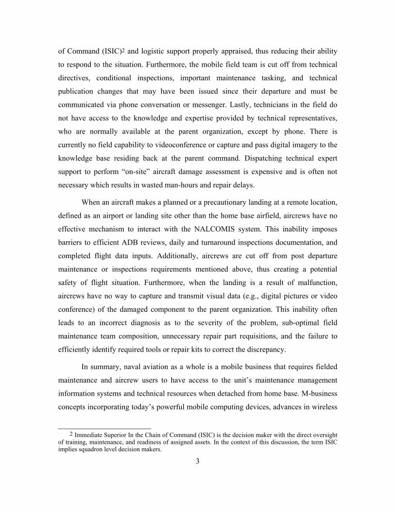
of Command (ISIC)2 and logistic support properly appraised, thus reducing their ability
to respond to the situation. Furthermore, the mobile field team is cut off from technical
directives, conditional inspections, important maintenance tasking, and technical
publication changes that may have been issued since their departure and must be
communicated via phone conversation or messenger. Lastly, technicians in the field do
not have access to the knowledge and expertise provided by technical representatives,
who are normally available at the parent organization, except by phone. There is
currently no field capability to videoconference or capture and pass digital imagery to the
knowledge base residing back at the parent command. Dispatching technical expert
support to perform “on-site” aircraft damage assessment is expensive and is often not
necessary which results in wasted man-hours and repair delays.
When an aircraft makes a planned or a precautionary landing at a remote location,
defined as an airport or landing site other than the home base airfield, aircrews have no
effective mechanism to interact with the NALCOMIS system. This inability imposes
barriers to efficient ADB reviews, daily and turnaround inspections documentation, and
completed flight data inputs. Additionally, aircrews are cut off from post departure
maintenance or inspections requirements mentioned above, thus creating a potential
safety of flight situation. Furthermore, when the landing is a result of malfunction,
aircrews have no way to capture and transmit visual data (e.g., digital pictures or video
conference) of the damaged component to the parent organization. This inability often
leads to an incorrect diagnosis as to the severity of the problem, sub-optimal field
maintenance team composition, unnecessary repair part requisitions, and the failure to
efficiently identify required tools or repair kits to correct the discrepancy.
In summary, naval aviation as a whole is a mobile business that requires fielded
maintenance and aircrew users to have access to the unit’s maintenance management
information systems and technical resources when detached from home base. M-business
concepts incorporating today’s powerful mobile computing devices, advances in wireless
2 Immediate Superior In the Chain of Command (ISIC) is the decision maker with the direct oversight
of training, maintenance, and readiness of assigned assets. In the context of this discussion, the term ISIC implies squadron level decision makers.
4
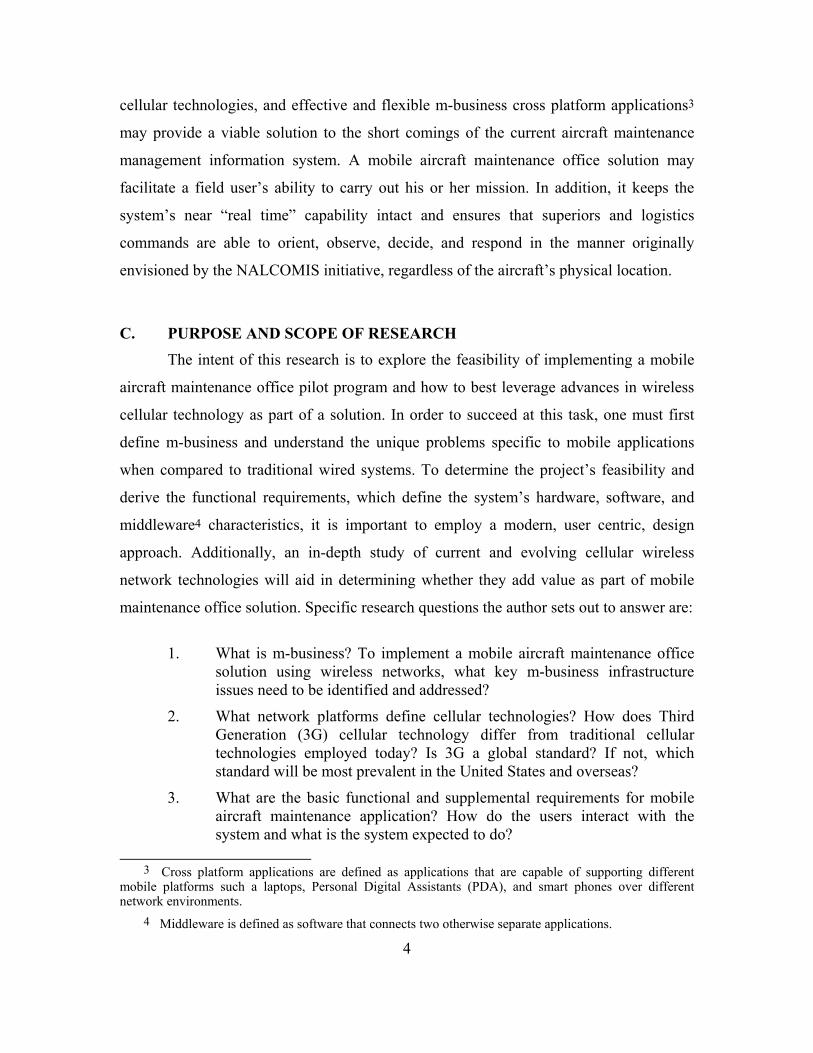
cellular technologies, and effective and flexible m-business cross platform applications3
may provide a viable solution to the short comings of the current aircraft maintenance
management information system. A mobile aircraft maintenance office solution may
facilitate a field user’s ability to carry out his or her mission. In addition, it keeps the
system’s near “real time” capability intact and ensures that superiors and logistics
commands are able to orient, observe, decide, and respond in the manner originally
envisioned by the NALCOMIS initiative, regardless of the aircraft’s physical location.
C. PURPOSE AND SCOPE OF RESEARCH The intent of this research is to explore the feasibility of implementing a mobile
aircraft maintenance office pilot program and how to best leverage advances in wireless
cellular technology as part of a solution. In order to succeed at this task, one must first
define m-business and understand the unique problems specific to mobile applications
when compared to traditional wired systems. To determine the project’s feasibility and
derive the functional requirements, which define the system’s hardware, software, and
middleware4 characteristics, it is important to employ a modern, user centric, design
approach. Additionally, an in-depth study of current and evolving cellular wireless
network technologies will aid in determining whether they add value as part of mobile
maintenance office solution. Specific research questions the author sets out to answer are:
1. What is m-business? To implement a mobile aircraft maintenance office
solution using wireless networks, what key m-business infrastructure issues need to be identified and addressed?
2. What network platforms define cellular technologies? How does Third Generation (3G) cellular technology differ from traditional cellular technologies employed today? Is 3G a global standard? If not, which standard will be most prevalent in the United States and overseas?
3. What are the basic functional and supplemental requirements for mobile aircraft maintenance application? How do the users interact with the system and what is the system expected to do?
3 Cross platform applications are defined as applications that are capable of supporting different
mobile platforms such a laptops, Personal Digital Assistants (PDA), and smart phones over different network environments.
4 Middleware is defined as software that connects two otherwise separate applications.

5
4. Is there a mobile computing model that is best suited for the mobile aircraft maintenance application? Will wireless cellular networks sufficiently support the requirements of the mobile maintenance office application?
5. Is the mobile aircraft maintenance office concept feasible and does it add value to the naval aviation maintenance information management system?
D. ASSUMPTIONS
There are certain assumptions the author made in writing this thesis. Specifically,
that NALCOMIS and other automated maintenance management information systems
will remain as a part of the Chief of Naval Operation’s Web Enabled Navy (WEN)
initiative. Another key assumption is that the cellular network operators will deploy
nationwide 3G systems as they are envisioned today. Though there is an extensive review
of key concepts provided in this thesis, it is assumed the reader has a basic understanding
of networks, the associated functionality of their components, and the Internet Protocol
(IP).
E. THESIS ORGANIZATION The thesis is organized into four chapters and three appendices. Chapters I and II
provide an introduction to the key concepts and issues regarding m-business and the
required infrastructure functionality that make it feasible. Chapter III concentrates on
determining an effective development approach and deriving functional and non-
functional system requirements using the Unified Process (UP) and scenario-driven Use
Cases. Chapter IV summarizes the conclusions derived from the research and
recommends areas for further research. A detailed survey of the evolution of cellular
technologies, a review of the 3G specification, the issues surrounding its implementation,
and an in-depth technical discussion of the two most predominant 3G system
architectures, data capabilities, and required protocols is presented in the three
appendices and are referenced throughout this thesis.

6
THIS PAGE INTENTIONALLY LEFT BLANK
7
II. MOBILE BUSINESS APPLICATION
A. INTRODUCTION Naval aviation maintenance has evolved from a paper-based system to a PC
centric system over the last decade. NALCOMIS began as a UNIX based, client-server
system that primarily focused on automating the existing maintenance, flight data and
supply chain process. In the beginning of 2000, the system’s evolution continued
emphasizing aircraft maintenance process reengineering and the implementation of the
Windows NT based, NALCOMIS Optimized program. As of this writing NALCOMIS,
as part of the Naval Tactical Command Support information System (NTCSS), is
identified as one of the information systems slated for conversion from an application
specific system to a browser based, web enabled system as part of the Navy’s Web
Enabled Navy (WEN) initiative. The WEN electronic business5 (e-business) initiative
combined with the increasing mobile device computing power, significant improvements
in wireless network data rates, and enhanced mobile application platforms offers an
opportunity to effectively integrate m-business applications into the next generation
NALCOMIS.
The Navy’s Task Force Web, as chartered by the WEN initiative, is developing a
strategy to take advantage of web technologies in order to create integrated and
transformational information exchanges. The ultimate goal of this effort is to deliver the
user a personal view, via a single portal, of Navy business and operational systems, and
promote interoperability between Navy enterprises using the Navy eXtensible Mark up
Language (XML) Infrastructure (NXI) interface (Task Force Web, 2001). Figure 1
captures the essence of the envisioned WEN architecture.
5 E-business is defined as Business to Business (B2B) and Business to Employee (B2E) activities conducted using electronic data transmission over the Internet and World Wide Web and usually designed to interface with existing back office systems.

8
Figure 1. Three Tiers of the Web Enabled Navy.
(From: Task Force Web, (2001), p. iv)
This e-business initiative lays a solid foundation for integrating mobile business
into the envisioned framework. However, it is important to realize that e-business
initiatives employing web technologies do not automatically translate into effective
wireless m-business applications. Mobile business applications and infrastructure have to
account for the unique characteristics of the wireless network environment, the multitude
of different device profiles, and the limited computing, memory, and battery capacity of
mobile computing devices. Electronic business applications designed specifically for the
wired web do not have to account for these types of variables.
As mentioned above, NALCOMIS will be transformed from a stove piped wired
network application into that of a web enabled e-business system. This transition is the
next evolutionary step in the automated maintenance environment, but fails to identify
maintenance applications that can enhance the new systems capability by implementing

9
both mobile and wireless technology. Aircrew and maintenance personnel routinely
conduct operations and maintenance away from their parent command housing
NALCOMIS, making mobility6 and wireless access to portions of the system a valid
requirement.
Prior to the automation of the aircraft maintenance management process, the
maintenance, flight data, and supply processes of the parent command matched that of
fielded teams and aircrew. Whether home or away, aircrew and maintenance personnel
used the same, paper-based system utilizing maintenance action forms, aircraft release
sheets, Naval Flight Reporting Subsystem (NAVFLIRS) and replacement part request
forms to capture aviation data. With the introduction of NALCOMIS, parent command
processes benefited from a client-server PC centric system that streamlined aircraft,
flight, and supply management. The system captured information and made it available to
personnel, with proper authority to access the system, from any PC connected to the
network. However, when detached from the parent command, personnel use stand-alone
NALCOMIS laptop computers or paper-based procedures to display or capture aircraft
maintenance, flight, and supply management data. This ad hoc process results in a
breakdown in information sharing between maintenance managers at the parent command
and the fielded personnel. The accepted method for synchronization of data between the
two entities during field maintenance or during cross-country flights is via phone or naval
message. Upon return, information is either uploaded or re-entered into the parent
command’s NALCOMIS database. This process effectively negates the intended
efficiencies and effectiveness envisioned by the original creators of NALCOMIS and
results in wasted man-hours, decreased supply chain efficiency, and increased aircraft
down time.
Optimized for the wired Internet environment, the next generation NALCOMIS
will not likely be suitable for the wireless mobile environment. To avoid this shortfall, it
is imperative, that the next generation NALCOMIS architecture address m-business’
concepts, issues, and constraints from its inception. Specifically, the new NALCOMIS
6 Mobility is defined as a portable platform capable of both online, near real time Internet transactions,
and offline operations that can be later synchronized to the central system.

10
development process must identify aircraft maintenance management applications that
are well suited and can add greater value through wireless m-business applications. These
initial applications will form the necessary foundation in the core architecture to facilitate
a more cost effective and integrated approach and enhance the system’s overall
effectiveness.
Business experts see m-business as the next evolutionary development after e-
business. Naval aviation maintenance decision makers must understand the mobile
wireless landscape and explore the requisite m-business concepts, architectures, and
integration issues necessary for successful implementations. There is a strong business
case for a mobile aircraft maintenance capability and it is long overdue. The WEN
initiative combined with the next generation NALCOMIS development provides the
opportunity to program an integrated m-business architecture into WEN framework from
the ground up reducing overall system and integration costs over the long run.
B. MOBILE BUSINESS DEFINED The concept of m-business is not new. Organizations employ different levels of
m-business through mobile sales, repair services, and emergency response teams in order
to extend the core competencies of the organization to field applications. That is,
organizations optimize certain value adding processes, whether paper, radio or computer
based, by extending the reach of corporate office assets to locations outside the office
walls. Mobile business is not tied to technology, it is a user facing, value-adding concept
in which field transactions and processing are integral pieces of the organizations
business model. However, improvements in wireless network and mobile computing
technologies make extending the organization’s reach easier, more cost effective, and
more data capable than in the past.
To develop a current working definition for wireless mobile business, one must
look at current electronic business concepts and enabler mobile computing technologies
that are making it more cost effective to employ. The Internet has made possible such
concepts as electronic commerce (e-commerce), which is nothing more than the buying
and selling of products and services over the Internet. E-commerce revolutionizes how

11
business is conducted and introduces “virtual stores” and “click and mortars” both which
have gained widespread adoption by consumers.
E-business evolved from e-commerce. Electronic business includes e-commerce
and all front and back office applications that drive modern business transactions
(Kalkota & Robinson, 2002). To date, the e-business paradigm has centered on the wired
Internet infrastructure and fixed or stationary users. However, advances in wireless
networking and mobile computing combined with the widespread adoption of these
technologies usher’s in the concept of mobile commerce (m-commerce).
Mobile commerce is simply defined as business transactions conducted while on
the move. There is a lot of hype surrounding m-commerce and some initiatives may be
too optimistic; however, m-commerce is likely to grow and mature as more users seek
out ways to conduct business, communicate, and share information while away from their
desks. Companies such as Federal Express, Progressive Insurance, and State Farm
Insurance have identified key business aspects that are suitable for m-commerce. These
companies are reengineering their internal business processes and employing mobile
technology to reduce costs, improve productivity, and increase overall responsiveness to
customer claims (Lykins, 2002). The natural extension to m-commerce is mobile
business, which encompasses everything that happens behind the scene to enable m-
commerce transactions from both online and offline mobile devices.
An implementation definition of m-business suitable for the mobile aircraft
maintenance office concept can be derived by combining elements from Ravi Kalakota
and Marcia Robinson (2002) and Nicholas Evans’ (2002) m-business equations:
M-Business = Process Reengineering + Internet + Wireless + E-business
Process reengineering for m-business is the most critical and most difficult component of
the equation. Without it, even the most effective combination of the Internet, wireless,
and e-business technologies will likely result in failed m-business initiative attempts.
Process reengineering forms the glue that holds the other three components together to
create successful m-business initiative. For the mobile aircraft maintenance office,

12
process reengineering must lead the m-business initiative and will lay the foundation for
a user centric design approach required to design and implement the concept.
The equation above reveals the complementary nature of m-business to present or
evolving e-business initiatives. Not as easily seen from the equation are the unique
aspects of the wireless components that compound m-business implementation. The
wireless components, which include wireless networks and associated mobile devices,
introduce different bandwidth characteristics and computing constraints that make the
wireless Internet experience very different from the fixed wired Internet. These unique
wireless characteristics include, but are not limited to, non-ubiquitous wireless coverage,
variable bandwidth, different transmission protocols and device operating systems,
varying display size and resolution, less storage capacity and significant battery life
constraints. It is also important to note m-business encompasses both “always-on-and-
connected” also referred to as “online” and the “on-demand” or “offline” mobile
computing models. The choice of which model to implement is dependent on the nature
of the organization’s business model. The “online” model supports real time transactions
and information sharing whereas the “offline” model affords the user more ubiquitous
access to critical information, however, requires synchronization via wired or wireless
network after a transaction is completed.
It is important for naval information system decision makers to identify and
understand the implications involved in integrating m-business capabilities into the next
generation NALCOMIS. What differentiates m-business from e-business is the use of
mobile computing and wireless technology. E-business is a tethered PC centric concept,
whereas m-business extends the e-business model to an anytime and anywhere capability.
To more accurately determine if the mobile maintenance concept is feasible, IT decision
makers should survey the mobile landscape to gain insight into both the capabilities and
the implications involved in extending e-business initiatives to include m-business
applications.
13
C. THE MOBILE LANDSCAPE Network infrastructure, hardware, and mobile application platforms housing the
necessary middleware software comprise the mobile landscape. The m-business network
infrastructure includes wireless local area and wide area technologies that encompasses
terrestrial radio and satellite based systems, however the focus of this research will limit
the discussion to terrestrial systems. The mobile device hardware discussion introduces
issues unique to mobile computing devices. Lastly, an investigation into mobile
application platforms will reveal the middleware functionality required to successfully
extend suitable e-business initiatives to mobile users.
1. Wireless Local Area Networks (WLAN) Wireless LAN technology has been a key enabler to local area m-business
initiatives. It affords manufacturing and retail companies the capability to conduct real
time inventories utilizing bar code scanning capable Personal Digital Assistants (PDA)
that are wirelessly linked to the central inventory databases. Mobile business initiatives
like the one mentioned above combined with the requisite process reengineering have
resulted in increased productivity while reducing inventory accounting errors. There are
many WLAN standards currently available and it is unclear which standard will likely be
the predominant standard two years from now.
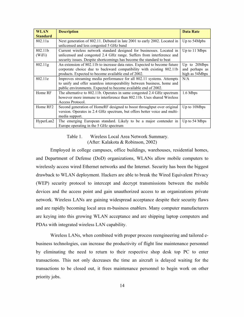
The Institute of Electrical and Electronics Engineers (IEEE) has put out a series of
802.11 standards that allow computer users equipped WLAN air interface cards to roam
through a building while remaining connected to the wired network. These wireless
systems have the ability to integrate into an existing wired Ethernet LAN or can form ad
hoc, strictly wireless, network between two or more computers. The 802.11 series
WLANs have an indoor radius of about 450 feet and about 1000 feet outdoors.
Theoretical data rates range from 11 Mbps for the 802.11b to 54 Mbps for 802.11a
standard. Competing WLAN technologies to the 802.11 standard are HomeRF and the
European HyperLAN2 standards. Table 1 summarizes the predominant WLAN
standards.
14
WLAN Standard
Description Data Rate
802.11a Next generation of 802.11. Debuted in late 2001 to early 2002. Located in unlicensed and less congested 5 GHz band
Up to 54Mpbs
802.11b (WiFi)
Current wireless network standard designed for businesses. Located in unlicensed and congested 2.4 GHz range. Suffers from interference and security issues. Despite shortcomings has become the standard to beat
Up to 11 Mbps
802.11g An extension of 802.11b to increase data rates. Expected to become future corporate choice due to backward compatibility with existing 802.11b products. Expected to become available end of 2002.
Up to 20Mbps and perhaps as high as 54Mbps
802.11e Improves streaming media performance for all 802.11 systems. Attempts to unify and offer seamless interoperability between business, home and public environments. Expected to become available end of 2002.
N/A
Home RF The alternative to 802.11b. Operates in same congested 2.4 GHz spectrum however more immune to interference than 802.11b. Uses shared Wireless Access Protocol.
1.6 Mbps
Home RF2 Second generation of HomeRF designed to boost throughput over original version. Operates in 2.4 GHz spectrum, but offers better voice and multi-media support.
Up to 10Mbps
HyperLan2 The emerging European standard. Likely to be a major contender in Europe operating in the 5 GHz spectrum
Up to 54 Mbps
Table 1. Wireless Local Area Network Summary.
(After: Kalakota & Robinson, 2002)
Employed in college campuses, office buildings, warehouses, residential homes,
and Department of Defense (DoD) organizations, WLANs allow mobile computers to
wirelessly access wired Ethernet networks and the Internet. Security has been the biggest
drawback to WLAN deployment. Hackers are able to break the Wired Equivalent Privacy
(WEP) security protocol to intercept and decrypt transmissions between the mobile
devices and the access point and gain unauthorized access to an organizations private
network. Wireless LANs are gaining widespread acceptance despite their security flaws
and are rapidly becoming local area m-business enablers. Many computer manufacturers
are keying into this growing WLAN acceptance and are shipping laptop computers and
PDAs with integrated wireless LAN capability.
Wireless LANs, when combined with proper process reengineering and tailored e-
business technologies, can increase the productivity of flight line maintenance personnel
by eliminating the need to return to their respective shop desk top PC to enter
transactions. This not only decreases the time an aircraft is delayed waiting for the
transactions to be closed out, it frees maintenance personnel to begin work on other
priority jobs.
15
2. Wide Area Wireless Data Networks Though WLAN’s are fundamental technology enablers for local m-business
efforts, a wide area wireless network covering large geographic areas is required to truly
enable “anytime and anywhere” aircraft maintenance management. A primary objective
of this research is to understand the data capabilities of and limitations of current and
soon to be introduced wide area cellular networks. Without a viable wide area wireless
capability, the mobile aircraft maintenance office will likely be infeasible, as the link to
the parent command will fail to be reliable.
Information systems decision makers need to understand how the cellular industry
has evolved to better understand the implications, complexities, and constraints that
affect present and future m-business network infrastructure. A detailed discussion of the
evolution of cellular systems and their strengths, weaknesses and data capabilities is
presented in Appendix A.
Data over cellular capabilities have matured from their humble beginnings in the
early 1980’s with the introduction of analog, Frequency Division Multiple Access
(FDMA) system voice systems. These systems include the Advanced Mobile Phone
System (AMPS), Nordic Mobile Telephone (NMT) and Total Access Communications
System (TACS). The United States deployed AMPS, Europe deployed NMT and TACS
and Japan deployed a modified version TACs called J-TACs. These 1G systems suffered
from four major shortcomings: capacity (in terms of users per cell), security, quality of
service, and no ability to transmit digital data7. Despite these shortcomings, 1G cellular
systems were very successful and form the bedrock from which viable m-business
enabling cellular technologies evolved. Although the 1G systems offer relatively
comprehensive geographic coverage and are still in use, they only satisfy the mobile
maintenance office’s voice needs and are not suitable for the data requirements.
Today’s cellular landscape evolved from the analog, voice only, first generation
systems and now include more complex and secure Second Generation (2G), Two point
Five Generation (2.5) and Third Generation (3G) digital voice and data networks. Each of
these generations builds upon their predecessor’s shortcoming while incorporating new
7 However, 1G cellular phones could serve as modems for mobile computers.

16
features perceived as required by the customer. Second generation systems introduced
digital transmission techniques, greater capacity via Time Domain Multiple Access
(TDMA) and Code Division Multiple Access (CDMA) technologies8, improved security,
and the ability to directly transmit digital data. These networks relied on circuit switched
technology for both voice and data services. The predominant 2G technologies are Global
System for Mobile communications (GSM), IS-136 sometimes referred to a D-AMPS
and IS-95A/B CDMA. According to Harte, Levine and Kikta, (2002) GSM is the world
leader in digital cellular systems with over sixty percent of the global market share with
CDMA capturing approximately twelve percent as of 2001.
All 2G systems have improved authentication and voice privacy capability and
introduce new features such as Short Messaging Service (SMS) and web browsing via
micro browsers. Reports indicate that SMS has become very successful and popular with
consumers and businesses alike. However, the wireless web has failed to live up to
consumer expectations primarily due to slow connection speeds averaging 10 kbps,
Wireless Application Protocol (WAP) shortcomings, lack of suitable WAP friendly web
sites, and the small monochrome displays on the mobile devices.
Second generation systems may satisfy the mobile maintenance office users voice
and text data requirements, however, it is believed the user experience will be less than
desirable due to the slow throughput and the less than satisfying wireless web capability.
Packet switched technologies nor Internet Protocol (IP) are incorporated in most 2G-
network systems. Large file transfers and multimedia services such as video conferencing
are neither cost effective nor possible because of the low system data rates.
Cellular operators across the globe are currently migrating their 2G GSM, D-
AMPS or IS-95A/B CDMA network platforms to either 2.5G or 3G networks in response
to customer demands for higher data rates and multimedia services. Cellular data systems
such as Cellular Digital Packet Data 9(CDPD), which are satisfactory for facsimile and
short text only email transfers, may be giving way to more capable systems. Transitional
8 TDMA and CDMA are explained in Appendix A. 9 CDPD was designed as a digital packet switched, data only, system overlay to the existing AMPS
networks capable of providing up to 19.2 kbps that is shared between the system’s users.
17
2.5G systems use improved digital radio technology to increase data transmission rates
and new packet based technology to increase system efficiency for data users (Harte,
Levine and Kitka, 2002).
Cellular operators are integrating 2.5G digital cellular packet data systems into
existing 2G networks and include General Packet Radio Services (GPRS), Enhanced
Data Rates for GSM Evolution (EDGE) and CDMA2000 1xRTT technologies. These
systems can provide theoretical data rates ranging from 64 kbps for IS-95B, 144 kbps for
GPRS and CDMA2000 1X, and 384 kbps for EDGE. However, the two predominate
2.5G systems, GPRS and CDMA2000 1xRTT, have observed average data transfer rates
of approximately 40-60 kbps under normal conditions. These improvements potentially
bring the mobile maintenance office throughput and Internet experience up to the same
quality as that experienced via 56k telephony modems. These enhancements offer
improved voice, data, and web browsing capabilities over 2G systems and better meet
voice and data requirements of the mobile maintenance office. However, large file
transfers and video conferencing are still not feasible with the exception of EDGE and
coverage is still limited when compared to 2G network coverage footprints but is
expanding every month.
It is important to note, the choice of which 2.5G technologies an operator chooses
to deploy is highly dependent on whether the existing 2G systems are TDMA (GSM or
IS-136) or CDMA (IS-95) based. Refer to Figure 4 located in Appendix A for a more
detailed description of the various migration paths towards 3G services. The GPRS and
EDGE systems are not compatible with CDMA2000 1xRTT. In the United States,
CDMA2000 1xRTT and GPRS/EDGE standards are deployed and impose coverage and
compatibility issues for IT managers. For example Sprint PCS and Verizon Wireless are
upgrading their 2G CDMA systems to CDMA2000 1xRTT while AT&T, Cingular, and
T-Mobile are integrating GPRS into their existing TDMA based GSM networks. Unlike
their European and Asian counterparts, American IT managers have to decide which
network best meets their m-business initiatives coverage in North America and around
the globe.

18
In response to customer demand for new features and services the International
Telecommunications Union’s (ITU) drafted plans for a third generation system called
Universal Mobile Telephone System (UMTS) in the early 1990s. The original
requirements for the system were defined in International Mobile Telephone-2000 (IMT-
2000) specification. The global specification required the UMTS system to be capable of
broadband data services, simultaneous voice and data operations (multi-media), improved
system efficiency, and backward compatibility with 2G systems. Issues such as globally
available common spectrum, operator migration costs, and other technological and
political issues led to compromises in the original International Mobile Telephone-2000
(IMT-2000) specification. Appendix B presents the history, definition, and evolution of
IMT-2000 in addition to spectrum issues and compromises that have added to the
confusion surrounding 3G systems. These compromises resulted in multiple migration
paths for cellular operators based primarily along existing 2G or 2.5G TDMA or CDMA
lines and is summarized in Figure 6 located in Appendix B.
The different cellular platforms will likely coexist for many years to come as the
ITU’s vision of a completely new 3G UMTS global system appears unlikely to
materialize as originally envisioned. Operators employing GSM and IS 136 are very
likely to pursue GPRS/EDGE transitional implementations towards the Wideband-
CDMA (W-CDMA) standard. Operators with IS 95A/B networks will likely integrate
CDMA2000 1xRTT transitional technology while on the path to CDMA2000 Multi
Channel (MC) standard. These two 3G platforms are likely to be the two most
predominant platforms from the five that comprise the IMT-2000 specification. These
diverging paths place barriers to network inter-compatibility that is key to true global
roaming, thus complicating global m-business initiatives from a wireless network
perspective. The result of this technology divergence will be felt more in the United
States as different operators deploy competing standards unlike their European and Asian
counterparts. Experts believe the answer to intersystem compatibility lies in the
deployment of inexpensive multi-mode mobile devices. The successful development and
deployment of these multi-mode devices is key to roaming between W-CDMA and
19
CDMA2000 networks and may prove critical in providing a global mobile aircraft
maintenance capability.
The key improvements in 3G that are different than 2G and 2.5G cellular
technologies include better packet data control, high-speed data transmission, multiple
radio channel bandwidths and multiple channel data rates. W-CDMA and CDMA2000-
MC achieve their superiority over 2G and 2.5G systems through improved modulation
schemes, increased coding combinations, and the ability to group multiple channels to
achieve the required bandwidth needed by a specific data service. Appendix C details W-
CDMA and CDMA2000 concepts, components, and architecture that make them superior
to previous cellular data services. As required by the IMT-2000 specification, these
systems offer 144 kbps at vehicular speeds, 384 kbps at pedestrian speeds, and 2 Mbps in
a stationary indoor environment. Both W-CDMA and CDM2000-MC system data rates
assume best effort quality of service. Actual data rates may be significantly slower based
on the quantity of data users and the types of services requested, network load, and
environmental conditions affecting radio frequency propagation.
The increased capacity, bandwidth, and improved services offered by 3G systems
make them the mobile aircraft maintenance office wide area network of choice. It appears
these systems will offer satisfactory bandwidth for voice, data, web browsing and
multimedia requirements. These systems’ larger file transfer, improved web browsing,
and video conferencing capabilities enable fielded maintenance technicians, managers,
and aircrew to effectively connect back to the parent command’s knowledge base which
was not possible with older cellular digital data services. However, these wireless
networks provide bandwidth on demand and are constantly adjusting throughput based on
network conditions. Additionally, a given mobile application has to satisfactorily deliver
the requested information to a mobile device at the 144 kbps, 384 kbps or 2 Mbps
(pedestrian, vehicular or stationary), and every throughput speed in-between. This
requires a very different software application and infrastructure development approach
than that for wired applications. Wireless m-business applications, especially those under
the “online” model, require a more specialized infrastructure. This infrastructure must be

20
capable of handling these unique wireless network characteristics and optimize the
content being delivered to the user for the given connection speed and network condition.
It appears improvements in wireless local and wide area networking offer
technological enablers for modern wireless mobile business initiatives. Figure 2 provides
a summary comparison of the different cellular networks. These technologies introduce
new complexities, such as wireless security, “online” and “offline” transaction
processing, and the delivery of tailored services to the user based on the conditions of the
wireless network. Additionally, 2.5G and 3G networks are in their infancy. As of October
2002, Japan, Korea, Austria and the United States (very limited in scope) are the only
countries that have deployed true 3G systems (3G is Here Today – 3G Operators, 2002).
For the most part the United States and European operators are employing 2.5G
transitional technologies on their way towards 3G and are expected to roll out full 3G
capabilities within the next two years.
Decision makers must be very cognizant of the trends of the wireless industry as
there is going to be a “shake out” period as different operators and vendors attempt to
best position themselves to gain market share. Coverage areas, inter-network
compatibility, and pricing schemes are likely to change considerably from their current
state as the industry matures. Regardless of the wide area wireless network adopted, the
mobile maintenance office infrastructure must provide a satisfactory user experience, add
value to the process, and properly safeguard against unauthorized information disclosure
and intrusion into the organizations private network.

21
Figure 2. Comparison of 1G, 2G, 2.5G, and 3G Networks.
(After: Evans, 2002)
D. MOBILE DEVICE HARDWARE The mobile device is the primary interface between the user and the voice or data
information they are seeking. The world has seen mass proliferation of hundreds of
mobile devices including pagers, cell phones, PDAs, sub notebooks and laptop PCs. It is
not unusual to see people carrying around three, four, or five different portable devices
each serving a different function. Fortunately, the recent trend is toward device
convergence where one sees a single device performing multiple mobile functions.
Examples include cell phones incorporating more computing features, commonly referred
to as “smart phones” as well as PDA’s doubling as cell phones. Regardless of the “latest
rage” in mobile device technology, it is important that chosen mobile device fits the
functions required by the user in a way that maximizes user experience and mobile
application effectiveness.
One sees the processor speed, memory, display quality, and functionality of
mobile devices improving at break neck speeds. The goal of device manufacturers centers
around three design features: compact form, high performance, and low power
22
consumption (Kalakota and Robinson, 2002). It is obvious, that with the exception of
laptop PC, neither smart phone, PDA, nor sub notebook mobile devices match the
computing power, memory, display or input characteristics of their desktop PC
counterpart. Desktop PC processor clock rates recently surpassed the 2 GHz rate, while
one the most powerful PDA processors, Intel’s PXA250 Applications Processor, tops out
at 400 MHz10. PDAs using this processor have 1/5 the processing speeds as that
experienced by desktop users. This limitation when combined with the more complex
operating systems, 65,000 color displays, increased memory capacities, audio and
wireless networking interfaces, all which demand more of the processor’s resources,
mean that mobile software applications need to be very efficient.
A major consideration when deciding on a suitable mobile device is the display
size and color characteristics. One does not have the same experience surfing the Web
with a PDA as he or she would with a desktop computer. For one, most websites are not
formatted for display on browsers that are smaller the 640 x 480 (Dornan, 2002).
Secondly, resizing the aforementioned page to 320 x 240 does not necessarily fix the
problem, especially if the compressed content (text and graphics) becomes too cluttered
or small to be usable. This example does not even consider the various other smaller
smart phone, PDA, and sub notebook display sizes or color characteristics. The display
size and color issue is one of the main reasons why web enabled e-business initiatives do
not necessarily translate directly into mobile business applications. The scenario is even
more compounded when the target device is a smart phone. Their micro browsers require
the use WAP and either Wireless Markup Language (WML) or Handheld Device Markup
Language (HDML) instead of Hyper Text Markup Language (HTML).
To web-enable applications for use over the wireless Internet, HTML pages need
to be converted and formatted for the specific mobile device. The majority of the
configurable converter tools use XML as the intermediary language during the
conversion process to support the generation of the output in different formats (i.e.
10 It is important to note that when comparing two different mobile devices, such as the Palm and the Pocket PC, clock speed is not a good metric for performance. In this case, the Palm has a 16 MHz processor while Pocket PCs have up to 400 MHz clock speeds. Both systems are comparable in performance, however the extra complexities of the Window CE operating system requires Pocket PC devices to have more computing power than their Palm counterparts (Dornan, 2002).

23
Wireless Markup Language (WML) for smart phones and HTML for PDA’s). There is an
integrated approach which combines an automated converter and an XML/eXtensible
Style Language Transformation (XSLT) based transformation, which offers a framework
that can be used either as an off the shelf product or extended to develop custom
solutions. These integrated wireless suites are evolving to support not just the new
generation of wireless content, but also HTML interfaces on PCs, enabling a website to
support any form of client device (Ahmed, 2002).
A fundamental point in wireless mobile application development is that
information is specifically tailored and presented in a way that is optimized for the
mobile user’s role and the device in use. A one size fits all approach will likely result in
mobilized applications that do not meet the mobile users expectations or needs. One
device may not fit all the user requirements, so the organization may very well be
supporting multiple devices for a given wireless m-business application. For example, if a
maintenance technician needs to access technical schematics from the mobile device, a
PDA with a 240 x 320 display is an inappropriate device for this application. The
opposite holds true when an application only requires reviewing small text pages or
entering text into fields for a work request and a laptop or some other larger display
device is used. In the later case, a PDA is the more appropriate choice. Nicholas Evans
(2002) emphasizes the necessity in understanding the tradeoffs between the need to
standardize on devices, operating systems, and applications and the need to give
employees solutions that fit their specific work pattern behavior.
Another key implication with mobile devices is the types of user input interfaces.
Laptops and sub notebooks usually include a standard QWERTY keyboard, however
other wireless mobile devices use different input interfaces like handwriting recognition,
soft keyboards, micro-keyboards, and telephone style keypads. Again, it is important to
match the mobile application requirements to the most appropriate mobile device. Use-
Cases and application requirements analysis should give insight into the type and quantity
of data that the mobile user will enter via a mobile device. If a significant amount of text
data must be entered, devices with full QWERTY keyboards might be the most
appropriate. If requirements analysis determines only small amounts of text data will be

24
entered or if drop down boxes will be employed, a PDA with a micro-keyboard or
handwriting recognition may suffice. If an organization fails to match the task to the
proper device, it is likely to have negative consequences in terms of user satisfaction and
could jeopardize the initiative.
But the key to mobile business applications is their ability to go anywhere and
access data anytime. This requires extended operations on battery power. Despite
advances in battery technologies, they have not kept pace with the demands of higher
speed processors, wireless interfaces, greater memory capacity, and the bright 65,000
color displays. When designing the mobile business application, this factor must be a top
concern. As cell phones and PDAs converge and more robust computing capabilities are
demanded from the devices, battery life will prove to be critical in the mobile
environment. To illustrate, A Compaq IPAQ 3850 contains a 1.4Ah lithium-ion polymer
battery rated for approximately 10 hours of operation. Researching the validity of this
claim Ed Neisley in his article Chemical Attraction (Dr Dobb’s Journal, 2002),
discovered that if one uses the Liquid Crystal Display (LCD) backlight and actually runs
a few applications this time is reduced to about 3 hours. He goes further and points out
that using an external plug in devices like a micro drive and a wireless link the time is
further reduced to about 1.5 hours.
When reengineering a process for a mobile application, mobile device battery life
and its impact on the system must be a top consideration. Mobile application
requirements analysis should determine if power-taxing features such as 65,000 colors
LCDs, 400 MHz processors, or large amounts of memory are required for the specific
mobile function. Application development must also require the application software to
be more processor and memory efficient in order to reduce power consumption.
Additionally, it may be more economical from a battery management standpoint for the
application to handle the transaction “offline”, and then connect to the network for
transmission. This seems contradictory to the notion of “always-on and connected” but
may be necessary given the current battery technology. If the mobile application requires
extensive “online” transactions then the device power consumption specification is
critical and must be sufficient to handle the task. It is important to mitigate factors like
25
specific device hardware, software, and wireless networking requirements impacting
battery consumption when developing a wireless mobile application.
E. MOBILE APPLICATIONS PLATFORMS How does the mobile wireless infrastructure handle things mentioned above
including variable bandwidth, different protocols, the multitudes of different device
profiles, and the disconnected nature of mobile sessions? Also, how does a system
adequately integrate the organizations security policy and provide connectivity to
backend legacy systems? As one looks for a solution to address these requirements, it
becomes evident some intermediary platform must be able to handle the unique
characteristics of integrating mobile wireless applications.
The integrated m-business infrastructure must be adaptable and deliver the right
content to the right person when they need it and in a suitable format for the device in
use. Extending portions of NALCOMIS’ e-business functionality to a number of different
mobile devices creates a need for a single common infrastructure or platform (Kalakota
& Robinson, 2002). The next generation WEN NALCOMIS will be designed for viewing
on a standard desktop PC or notebook computer. Fielded technicians and aircrew will
likely carry small screen mobile wireless devices that require optimizing the applications
for quick data input and retrieval. If the “online” mobile model is chosen, the information
going to the mobile user must be completely reformatted from its desktop PC format to
ensure the best possible mobile user experience. It is imperative the mobile application
platform provide fielded maintenance and aircrew personnel access to NALCOMIS
information with no loss in transaction capability. It must also be able to deliver a
consistent user experience based on the type of mobile device and wireless network
connection speed.
The mobile application platform provides the specialized middleware required for
mobile computing. The middleware must support multiple mobile devices. This means
the middleware must be aware of the different device profiles and be capable of correctly
identifying a user’s particular device when requesting wireless service. It then adapts the
web-based content and applications to meet the device’s specifications, computing

26
capabilities and screen size, colors and mark up language formats. The integrated
automated converter and an XML/XSLT based transformation implementation
effectively illustrates this concept. In addition to adapting content and application to meet
the specific device, the mobile application platform should be capable of optimizing the
amount and format of content for delivery that is consistent with the mobile’s connection
speed.
An alternative to the “online” mobile model is the “offline” model employing
intelligent database synchronization. Offline mobile applications require fat11 mobile
clients, but provide the field user with the necessary information whenever and wherever
he or she needs it. This capability allows the user to conduct business transactions offline,
then, when complete or back in range of the wireless network, synchronize with the main
database to update the system. The ability to work offline to capture transactions, and
then intelligently synchronize data on demand is key as spotty wireless network coverage
and mobile device battery life may force the user to work offline. The synchronization
middleware is critical to the “offline” model and must be able to intelligently detect
changes in either database and either notify the user or automatically synchronize both
databases. This ensures both the main and replicated databases match and reflect any
transactions or updates that occurred while the user was offline.
Mobile synchronization technology may also offer a lower short and long term
risk and cost reduction. System development risk and initial costs are mitigated, as
synchronization technology is more mature and may require fewer components when
compared to “always-on” type mobile technologies mentioned above. With regards to
long-term cost of operating the mobile system, this technology reduces actual network
connection time to that required for database synchronization, thus reducing the mobile
devices air time bill. In his white paper titled “Mobile Enterprise Architecture - The
Choices”, Jim Flynn (2002) offers an even less expensive way of handling offline
synchronization in his “on demand” model. This model uses an enterprise database with a
11 The Webopedia.com website defines a fat client, in the context of the client server architecture, as a
client that performs the bulk of data processing operations. When the server performs the bulk of the processing operations and then presents the results to the client, the client is considered a thin client. In either case, the data is stored on the server.
27
back office application and reporting tool set that synchronizes across the Internet using
FTP or email (Flynn, 2002). Flynn’s research concludes that the initial cost of the “on
demand” model is approximately eight percent less expensive when compared to an
“always-on”, real time, active synchronization model and is at least fifty percent less
expensive annually to operate.
It is important to note, neither model was evaluated as superior to other, but
should be chosen based on the requirements of the user and the mobile application
stakeholders. Proper system requirements analysis and the envisioned operating
environment will determine whether the mobile application should be an online only,
offline only, or a combination of both. Regardless of mode, both online and offline
systems fall under the mobile computing umbrella.
Additionally, the mobile application platform should be scalable providing cost
effective support for future growth in the number of applications and user capacity. The
platform should also facilitate the development, maintenance, and management of
wireless capabilities as new applications and devices are introduced. It should support
existing Web infrastructure security standards and policy. Most importantly, the mobile
application platform should facilitate integration into existing e-business infrastructure.
This feature is key to reducing the need to recreate existing functionality and content
solely for wireless delivery.
When evaluating a vendor’s product, the above-mentioned functionality serves as
the minimum requirements for a suitable enterprise-class mobile application platform.
Fortunately, middleware vendors like 724 Solutions, JP Mobile, Briece, and ViaFone are
delivering high quality products that provide enterprise-class solutions to connect
organizations internal business applications to their mobile forces.
F. SUMMARY It is evident that enabling technologies such as 2.5G and 3G wireless networks,
mobile devices, and mobile application infrastructure have matured to the point where
they offer new value adding mobile business opportunities for naval aviation
maintenance management. Existing local and wide area wireless networks are providing
28
adequate bandwidth to support the minimum voice and data requirements. The mobile
force will benefit from third generation cellular network’s videoconferencing and larger
file transfer capabilities. However, e-business initiatives alone fail to account for the
implications imposed in the wireless mobile environment. The combination of multiple
radio protocols, the proliferation of hundreds of differing mobile device profiles,
inefficiencies of TCP/IP in a wireless setting, information security over the air interface,
unique data compression requirements, and the disconnected nature of mobile sessions all
contribute to the complexities that require an adaptable mobile application infrastructure.
One of the most critical points to be made is the integration of necessary m-
business infrastructure into the soon to be developed WEN NALCOMIS initiative. The
business case for mobilizing certain time and manpower saving maintenance
management processes is strong. The key is identifying the maintenance management
processes that are most suitable for wireless mobilization. Decision makers should choose
a relatively simple high-impact application that is capable of delivering a short-term
return on investment from the list of candidate applications. If successful, the cost of
establishing the mobile platform from which future mobile maintenance applications can
be built can be justified.

29
III. MOBILE AIRCRAFT MAINTENANCE OFFICE REQUIREMENTS DEVELOPMENT
A. INTRODUCTION Advances in mobile computing devices, adaptable infrastructure hardware and
software, and the Internet combined with wireless technology serve as technological
enablers that allow mobile users to capture aviation maintenance management
transactions when and where they occur. Mobile maintenance applications can
significantly facilitate information sharing between the fielded aircrew and maintenance
managers at the parent organization and could result in fewer errors, more effective
maintenance management, and significant cost savings in manpower and replacement
parts when situations requiring remote maintenance arise. To explore the feasibility of a
mobile maintenance office system and its benefits, it is imperative to choose a system
design approach and employ a sound development process like the Unified Process
(UP)12 with the Use Case methodology to discover key functional user and supplemental
requirements. This chapter will produce the basic artifacts associated with the UP’s
inception phase and includes the vision, Use Case model, and the first iteration of the
supplemental specification. Once the basic functional requirements are developed, one
can get a sense of system data flows and the basic infrastructure components necessary to
better access the projects feasibility.
The complete mobile aircraft maintenance office will support, at a minimum,
three primary field users: aircrew, maintenance technicians, and maintenance managers.
Each user category requires a separate mobile maintenance office application; however,
this chapter will limit the scope of study to the aircrew application of the mobile
maintenance office. The process used to develop the aircrew application’s vision, Use
Case model, and functional and supplemental requirements is sufficient to determine the
project’s overall feasibility and is representative of the envisioned requirements for the
mobile maintenance technician and maintenance management applications. The primary
12 UP is used as an example process within which to explore requirements analysis and object oriented analysis and design. The process consists of four highly iterative and distinct phases: inception, elaboration, construction and transition (Larman, 2002, p. 14).

30
difference between the different applications is the user’s information requirements and
the type of mobile device used in the field. One can continue to employ the UP and
expand on the artifacts derived in this chapter for the aircrew application to accommodate
the requirements of the maintenance technician and maintenance manager. This is highly
recommended to ensure an integrated mobile maintenance system and lower the overall
system development costs. Regardless of user application, the basic mobile application
infrastructure will be capable of serving all three user’s mobile application needs
regardless of mobile device employed.
B. DESIGN APPROACHES FOR DEVELOPING THE AIRCRAFT MOBILE MAINTENANCE OFFICE When developing the aircrew mobile maintenance office application one can
choose from three different and distinct approaches; device centric, application centric
and user centric. Choosing the correct approach is critical to an organizations long-term
mobile application implementation success.
1. Device Centric Approach The device centric approach focuses primarily on each individual user device for
a distinct version of given application. For each type of mobile device deployed,
developers create a separate and distinct application. To illustrate, assume for a given
mobile application, sixty percent of field users utilize a Windows based laptop computer
to access the mobile application while thirty percent use Pocket PC PDA’s and ten
percent use smart phones. System developers develop and maintain separate applications
for each the three devices employed. This approach leads to longer development times,
makes upgrades difficult and expensive, and is not responsive to new user requirements
or device technology. Employing this outdated approach results in a slow to deploy,
expensive, and difficult to modify or upgrade mobile system (MobileQ, 2002).
It is foolish to think the mobile aircraft maintenance office concept will employ a
single device across all communities or user categories. This fact combined with the
diversity of mobile devices available and the need to properly match the mobile device to

31
the user’s required tasks and form factor make this approach unsuitable for the mobile
aircraft maintenance office.
2. Application Centric Approach The application centric approach attempts to build a single mobile application that
will function across multiple mobile devices. This “one size fits all” approach includes
attempts to extend Web content to wireless devices through such mechanisms as
transcoding and webscaping. This approach produces inherently unstable mobile
applications that are poorly integrated into the enterprise architecture (MobileQ, 2002).
The result of the application centric approach, which attempts to satisfy the majority of
the user’s need for a given device, is often a failure to deliver a satisfactory user
experience on any device. A good example of an application centric approach can be
demonstrated by accessing the Naval Postgraduate School’s Website with a PDA that is
wirelessly connected to the network. The PDA indeed displays the web page; however,
the user must scroll up and down as well as left and right to see the page in its entirety.
The result is a dissatisfying experience when compared to that of using a laptop or
desktop PC.
3. User Centric Approach The user centric approach is the most current and mature approach to mobile
application development (MobileQ, 2002). This philosophy places the user experience at
the forefront of development efforts rather than focusing on a particular device or
application. The goal of this approach is to refine the user experience for different
contexts without having to write, develop, and manage a distinct application for each type
of device utilized. This approach is the only viable approach that can survive for the long-
term in light of the blistering pace in which mobile device and wireless network are
evolving.
Mobile application software developed using the device centric or application
centric approach may result in technological dead ends without the ability to evolve or
extend into the user centric paradigm (MobileQ, 2002). It is imperative that the mobile
application development platform be user centric based and include tools for designing,

32
integrating, managing, deploying, securing and administering the mobile application.
Researching different vendors that produce field force automation mobile application
development platforms, such as Covigo, Sybase, and @Hand, it is apparent the user
centric approach is the mobile application development methodology of choice.
C. EMPLOYING THE UNIFIED PROCESS TO DETERMINE BASIC FUNCTIONAL REQUIREMENTS Use Case methodology within the UP framework greatly facilitates identifying
and developing mobile aircraft maintenance office actors and functional requirements.
All system notations, such as the Use Case diagram, employ the Unified Modeling
Language (UML) standards. The following paragraphs represent the activities that occur
during the inception phase of the UP. The goal of this investigation is to do just enough
investigation to form a rational, justifiable opinion of the overall purpose and feasibility
of the mobile aircraft maintenance application system (Larman, 2002). Ultimately, the
results of this inception phase determine whether the project warrants further
investigation and development.
1. The Aircrew Mobile Aircraft Maintenance Office Application Vision The mobile aircraft maintenance office vision extends the parent organization’s
automated aircraft maintenance and aircrew flight information system to fielded
personnel (terrestrial facilities only) while reducing the information transfer delay
between fielded personnel and the parent organization from days to minutes. The mobile
maintenance office system shall keep fielded aircrew, maintenance technicians and
maintenance managers, and the parent organization decision makers better apprised of the
latest aircraft and aircrew status. Additionally, the system shall facilitate voice, text, and
imagery transfer to aid in communication, safety of flight determination, and damage
assessment when situations warrant.
More specifically, the envisioned system will allow fielded personnel to review
required aircraft maintenance information during short, out of area operations, and
capture, process, and update new aircraft and aircrew information as if they were still at
the parent organization. The system shall provide any newly entered information back to
the parent organization’s NALCOMIS system in addition to forwarding new aircraft

33
information from NALCOMIS to the fielded user. The mobile aircraft maintenance office
system will build on and integrate with the WEN’s e-business initiatives to add greater
efficiency and effectiveness to remote aircraft operations and maintenance where wired
Internet service may not be available.
The ultimate objective of this extended capability is to minimize transaction
capture delay time, improve information flow between fielded entities and the parent
organization, and reduce maintenance and manpower costs associated with remote
operations/maintenance when compared to the processes employed today. The system
will ultimately result in improved aircraft safety, mission effectiveness, and reduce
maintenance costs and missed sorties due to the information delays and
miscommunications.
2. Scope Refinement and Governing Instructions As mentioned in the beginning of this chapter, the scope of the mobile
maintenance office system will be limited to that of required by fielded aircrew13 users
conducting routine, multi-leg, cross-country14 flights. The duration of the cross-country
scenario used in this study spans from twenty-four to seventy-two hours. The Naval
Aviation Maintenance Program (NAMP), OPNAVINST 4790.2 and the NATOPS
General Flight and Operating, OPNAVINST 3710.7 instructions provide the basic
information requirements for fielded aircrew personnel.
3. Maintenance Process Background Information Flying a naval aircraft involves a four step administrative process: aircraft
preparation, certifying the aircraft as “safe for flight”, aircraft acceptance, and post flight
accounting. As part of the preparation process, a plane captain first reviews the Aircraft
Discrepancy Book (ADB)15 for discrepancies that are awaiting maintenance and recently
13 The OPNAVINST 3710.8S defines aircrew as military personnel on competent flight orders or civilian personnel whose duties require frequent and regular participation in aerial flights (U.S. Navy Department, 2001).
14 A flight that either does not remain in the local flying area or remains in the local flying area and terminates at a facility other than an active military facility.
15 The ADB provides the current status, material condition, configuration, and safe for flight documentation of an aircraft and is used by maintenance managers, technicians, and pilots in command in carrying out their aircraft maintenance and flight preparation responsibilities. It contains the AIA, all open and closed work orders for the last ten subsequent flights, consumption data, near due inspections and component removals (NALCOMIS OMA USER Guide, 2002).

34
completed work orders. He or she also reviews other data included in the ADB to get a
feel for any trends in oil consumption. Next he or she performs both daily and turnaround
inspections and annotates their completion in the ADB prior to the first flight of the day.
The plane captain also signs the appropriate block of the Aircraft Inspection and
Acceptance record (AIA)16, signifying the completion of the daily and turnaround
inspection. This signature also marks the end of the aircraft preparation process.
Once the aircraft preparation process is complete the certification of the aircraft as
“safe for flight” begins. A designated “safe for flight” releasing maintenance control
supervisor reviews the ADB to ensure all required maintenance is complete, no
outstanding maintenance will affect the mission, daily and turn around inspections are
complete, and the aircraft is indeed “safe for flight” and ready for release to the pilot in
command. The “safe for flight” releasing authority adds any applicable aircraft
limitations or remarks to the “Limitations/Remarks” section of AIA and signs the
appropriate block of the AIA certifying the aircraft is “safe for flight”.
Prior to accepting the aircraft for flight the pilot in command follows a similar
process carried out by the maintenance control supervisor and is required by the two
aforementioned instructions to:
• Review a record of aircraft discrepancies and corrective actions for the 10 previous flights. This information is contained in the ADB.
• Sign the AIA record assuming full responsibility for the safe operation of the aircraft and the safety of the other individuals aboard.
The post flight logging process consists normally of two activities; annotating
new aircraft discrepancies discovered before, during, and after the flight and completing
the Naval Aircraft Flight Record (NAVLFIR) form. Additionally, during cross-country
operations, the pilot in command is also responsible for completing a “safe on deck”
voice report to the squadron duty officer. This voice report serves to inform the
operations office of the crew’s location and to close out that portion of the flight event on
the squadron’s flight schedule.
16 This record is part of the ADB and is commonly referred to as the “A-sheet”.

35
The parent organization’s NALCOMIS houses the database that contains the data
tables and input forms that comprise the above mentioned automated ADB and
NAVFLIR. NALCOMIS builds all the components that comprise the ADB through
predefined queries built into the system. All the entities access the ADB information
through a Windows based PC connected via an Ethernet LAN to the central NALCOMIS
server. NALCOMIS captures the three signatures annotated on the AIA digitally.
The OPNAVINST 4790.2 allows for certain exceptions to accommodate out of
area operations. The requirement to review the ADB prior to each flight still exists and
the preflight and post flight processes still occur in some fashion and still must be
captured and recorded by NALCOMIS. When the mission requires the aircraft to shut
down at a non-local field overnight, the aircraft requires another daily and turnaround
inspection. The OPNAVINST 4790.2H allows a squadron CO to authorize the pilot in
command to conduct a pilot’s preflight inspection to count in lieu of daily inspection for
periods not exceeding seventy-two hours (U.S. Navy Department, 2001). This exception
is primarily designed for single seat aircraft that cannot accommodate carrying properly
qualified plane captains as aircrew. However, multi-seat helicopters and fixed wing often
ensure the enlisted aircrew member is a qualified plane captain and is responsible for
completing and documenting the daily and turnaround inspections. In either case, the
pilot in command is responsible for certifying the aircraft “safe for flight” since a
maintenance control supervisor representative is not available.
4. Product Perspective and System Boundary The product perspective is an aircrew mobile maintenance application used by
fielded aircrew to access and update the required aircraft maintenance and flight
management programs and improve voice and digital communications while conducting
cross-country operations. Fielded users will interface with the system through portable
mobile devices. NALCOMIS will interact with the system via the parent organization’s
local area network and firewall. The mobile aircraft maintenance office application
system includes mobile devices, an available public voice and data network, and the
required servers and middleware in order to connect the fielded aircrew personnel and the
entities (NALCOMIS and duty officer) residing in the parent organization. Everything

36
outside the aircrew mobile application system is outside the system boundary, which
includes the fielded aircrew users and NALCOMIS.
5. System Goals The mobile system shall provide fielded aircrews with the necessary automated
capabilities to more effectively and safely conduct multi-leg, short duration (between
twenty-four and seventy-two hours) cross-country operations regardless of location. The
system should significantly reduce the delay in capturing and updating aircraft
maintenance and flight transactions and improve communications between fielded
aircrew and the parent organization’s maintenance and operations supervisors. More
specifically, the system goals include providing access to the required aircraft
maintenance information, the ability to process the required maintenance and flight
transactions to continue operations for up to seventy-two hours regardless of location,
update the NALCOMIS database residing in the parent command, and to keep the parent
command’s maintenance managers and operations supervisors better informed about the
current status of the aircraft and crew. Secondary goals include providing a means to
enable voice and data communications to improve aircrew and aircraft status and provide
a mechanism to transfer digital imagery to assist in damage assessment and field
maintenance team composition decision processes.
6. System Constraints and Simplifying Assumptions Based on the technology review conducted in Chapter II and the requirement that
the fielded users shall have the required aircraft ADB information regardless of location,
the system shall be capable of autonomous offline operations to facilitate field operations.
Because of this constraint, the primary method of updating the NALCOMIS database will
be via database synchronization versus “online” direct access method via a web browser.
Transient aircrews are constrained by the austere services and facilities available to them
while conducting cross-country operations. Because of this constraint, the system cannot
rely on wired telephone connections as the primary means of accessing a public data or
voice networks. Additionally, wireless voice and data network coverage is not ubiquitous
and is also a factor requiring the system to be capable of “offline” operations. The final
constraint is that the system’s mobile devices cannot rely on external sources for power

37
and must be capable of operating on battery power for at least three days or have a means
to recharge without relying on wired electrical outlets.
A key assumption is that a majority of civilian and military airports used by naval
aircraft are located near populated areas and are within a commercial wireless service
provider’s coverage area. Additionally, it is assumed the wireless carrier’s 2.5G and 3G-
rollout schedule continues as planned and services are deployed nation wide. This implies
that nationwide 2.5 or 3G cellular services will be available with at least the same
coverage as is available with today’s first and second-generation networks.
7. Identifying the Actors Analysis of the broad functional requirements, process background, and system
goals reveals at least five actors that will call upon the aircrew mobile maintenance
application to assist them in conducting cross-country operations. Of the five actors, the
pilot in command, plane captain, and NALCOMIS meet the definition of primary
actors.17 Another primary actor to the system is the system administrator who will
depend on the system to facilitate the system’s administration. However, NALCOMIS’
database also serves as the source database that provides the initial aircraft maintenance
data to the system, which qualifies it as a supporting actor as well. Providing more data to
the system than it receives, NALCOMIS is more of a supporting actor than a primary
actor in this application. The duty officer and maintenance supervisor are off-stage actors,
since they have an interest in the behavior of a Use Case but do not necessarily interact
directly with the system (Larman, 2002).
8. User Characteristics The bullets below succinctly describe how each of the primary and supporting
actors mentioned above utilize the system to fulfill their needs.
• The pilot in command utilizes the system to review ADB information, process maintenance transactions required to continue cross-country operations, input completed flight data information, release the aircraft as “safe for flight”, and make necessary voice and text reports for normal and exceptional maintenance and operational situations. Additionally, they would the use the system to capture digital imagery for transmission to the parent organization.
17 Primary actors have user goals fulfilled through using services of the system under design. This is in
contrast to supporting actors, which provide services to the system under design (Larman, 2002, p. 70).

38
• The plane captain utilizes the mobile system to review the required ADB information in order to properly conduct daily and turnaround inspections. He or she uses the system to access the appropriate inspection requirement cards and to capture the required preflight inspection transactions, process maintenance transactions, and digitally sign the appropriate block of the AIA.
• NALCOMIS interacts with the system to populate the remote database with initial aircraft maintenance data prior to the cross-county flight. Once the aircraft is detached, it provides and receives database updates to and from the system.
• The system administrator uses the system to manage users, security, and device configuration.
The two offstage actors, the maintenance manager and the duty officer, are
omitted from the above discussion because they receive their benefits from components
outside the system boundary. For example, the maintenance manager would receive
updated aircraft maintenance information via the NALCOMIS system not the mobile
maintenance office application system. Maintenance managers would also likely receive
any data or digital image messages via the organization’s email system not directly from
the mobile application system. The same is true with the duty officer who would receive
the “safe on deck” call via the normal telephone system and the NAVFLIR data via
NALCOMIS and not the system under design.
The actors described above all have specific goals that they hope the mobile
aircraft maintenance system will help satisfy. Craig Larman (2002) suggests that Use
Case development for computer based applications focus at the Elementary Business
Processes18 (EBP) or the user goal-level. Employing this strategy, one keeps the
emphasis on the user and his or her goals while avoiding the common mistake of defining
many Use Cases at too low of level; that is, a single step sub function or subtask within a
EBP (Larman, 2002). Investigating user goals better assists in developing the Use Cases
that define the aircrew mobile aircraft maintenance office application system’s
requirements. Actor-goal lists are simple tools used to document the actors and their
18 EBP is defined as “a task performed by one person in one place at one time, in response to a business event, which adds measurable business value and leaves data in a consistent state e.g., Approve Credit or Price Order” (Larman, 2002, p. 60).

39
specific EBP level goals. Each goal identified in the actor-goal list is later developed into
a Use Case. It is important to note the process of defining actors, their goals, and the
subsequent development of the respective Use Cases is highly iterative in nature and is
not considered the final product at the end of the inception phase. Instead, the UP
embraces changes to these artifacts as the developers and users progress through each of
the remaining three phases, which usually results in better overall user satisfaction and
system acceptance. Table 2 serves as the actor-goal list for the aircrew mobile aircraft
maintenance office application system under design.
Actor Goal Pilot in Command (primary) 1) Access ADB information for specific
aircraft 2) Process new AIA record 3) Process flight document (NAVFLIR) 4) Process new discrepancy 5) Synchronize database information 6) Capture digital images 7) Process text and data messages (e-mail) 8) Handle voice message transactions
Plane Captain (primary) 1) Access ADB information 2) Process Daily Inspection Record 3) Process Turnaround Inspection Record 4) Process new discrepancy 5) Access Daily and Turnaround Inspection Maintenance Requirement Cards (MRCs)
NALCOMIS (secondary) 1) Populate remote database 2) Synchronize database information
System Administrator (primary) 1) Manage users 2) Manage security 3) Manage device configuration
Duty Officer/Maintenance Supervisor (off stage)
1) Receive voice message transaction 2) Receive text and data messages (e-mail)
Table 2. Mobile Aircrew Maintenance Application System Actor-Goal List.
9. Use Case (UC) Development
The goals listed in Table 2 serve as the basis for developing Black-box Use
Cases.19 During the inception phase, the Use Cases developed are in a brief terse one-
paragraph format usually forming the main success scenario. Different actors listed in
19 Black-Box Use Cases are the most common and specifies what the system must do (the functional requirements) without deciding how it will do it (the design) (Larman, 2002, p. 49).
40
Table 2 share common goals and will be included in the applicable pilot in command Use
Cases to minimize redundancy. The pilot in command actor goals from Table 2 are
developed into brief format Use Cases below:
a. UC1: Access ADB The pilot in command or plane captain arrives at the location of the
aircraft and prepares to conduct his or her preflight inspection. Either user uses the
system to access the pertinent data of the ADB to determine the mission capability and
status of the aircraft. The system presents the user with the time stamp from the last
remote database update and lists available options for the user to choose. The user
chooses the ADB option. The system presents the user with an ADB submenu listing the
open work orders, closed work orders, oil consumption, engine/APU/prop data, aircraft
limitations/remarks, near due inspection, or component removal sections of the database
and includes the number of records per section. The user chooses a section from the
available options. The system presents the user with text data for the section chosen. The
user navigates through each record for the applicable section. The system notifies the user
when there are no more records for a particular section and returns to the ADB submenu.
The user repeats the process until he or she is satisfied with the review of the ADB
information. The user exits the system, departs for the aircraft and performs the preflight
inspection.
b. UC2: Initiate New AIA The pilot in command arrives at the aircraft location intending to initiate a
flight. The pilot in command uses the system to generate and capture AIA record
information in order to certify the aircraft as “safe for flight”. The pilot in command
initiates a new AIA record. The system queries the pilot in command to ensure all the
necessary data is entered in the AIA record’s fields and to verify the completion of the
steps required to certify the aircraft “safe for flight”. The pilot in command enters the
appropriate data or response to the queries. The system checks the open work order
database to ensure there are no “Z” coded discrepancies, also referred to as downers,
against the aircraft. The system prompts the pilot in command for the plane captain’s
signature. The plane captain enters the correct information to digitally sign the
appropriate block of the AIA. The system then prompts the pilot in command to sign and
41
certify the aircraft “safe for flight”. The pilot in command signs the appropriate block.
The system validates and records the transaction (updates the remote database). The pilot
in command initiates database synchronization with the local NALCOMIS database at
the parent organization or exits the system.
c. UC3: Process Flight Document (NAVFLIR) The pilot in command uses the system to record each flight during the
cross-country evolution. The system presents the pilot in command with a list of options
to choose. The pilot in command chooses the flight document option. The system
presents the pilot in command with required empty data fields necessary to capture and
record the flight data for a single or multiple legs as set forth by OPNAVINST 3710.7S.
The pilot in command enters the data into the fields. The system validates and records the
transaction. The pilot in command initiates database synchronization with the local
NALCOMIS database at the parent organization or exits the system.
d. UC4: Process New Discrepancy The pilot in command or plane captain uses the system to record new
discrepancies (work orders) discovered before, during, and after the flight. The system
presents the pilot in command with a list of options to choose. The user chooses the new
discrepancy option. The system presents the user with a series of questions, prompts or
fields to capture the necessary data fields. The user enters the appropriate text data. The
system validates and records the transaction. The user repeats the process until he or she
has finished entering all new discrepancies. The pilot in command initiates database
synchronization with the local NALCOMIS database at the parent organization or exits
the system.
e. UC5: Synchronize Database Information
The pilot in command uses the system to synchronize the local
(NALCOMIS) and remote (mobile device) databases in order to improve aircraft and
aircrew situational awareness with the parent organization. The system senses updates
and any changes to the remote database (examples include: new AIA, flight document, or
aircraft discrepancies) and determines the presence of network signal. The system
prompts the user to initiate an “online” synchronization. The pilot in command initiates
the synchronization processes. The system establishes a network connection, starts an

42
internal timer and synchronizes the two databases. The system closes the network
connection, stops the internal timer, updates the synchronization time stamp, and logs the
duration of the transaction when synchronization is complete. The system notifies the
pilot in command the number of changes to the remote database. The pilot in command
acknowledges the time stamp and changed information. The pilot in command reviews
the remote database changes or exits the system.
f. UC6: Capture Digital Imagery The pilot in command uses the system to capture digital images of aircraft
components that have sustained physical damage. The mobile device will have the ability
to serve as digital camera. The pilot in command uses the mobile device portion of the
system to capture digital images of the area of interest. The system presents the image for
review by the pilot in command. The pilot in command accepts the image and the system
names and stores the image file in the mobile device’s memory. The process repeats itself
until the pilot in command is satisfied the damage has been accurately documented. The
pilot in command exits the system.
g. UC7: Process Text and Data Message The pilot in command uses the system to transmit and receive text and
other data message to and from the parent organization. The pilot uses the mobile device
portion of the system to compose a text message. The system presents the pilot in
command with the required fields and text boxes to facilitate composing, routing, and
adding attachments. The pilot in command enters the applicable data and appends any
required attachments to be transmitted. The system validates the appropriate routing
fields. The system establishes a network connection, starts an internal timer and transmits
the message and attachments. The system receives incoming messages. Once the
outbound and inbound transactions are complete, the system breaks the connection and
logs the connection duration. The system informs the pilot in command that the
transaction is complete and informs him or her of any new messages. The pilot in
command reviews his or her new messages or exits the system.
h. UC8: Process Voice Message
The pilot in command uses the mobile device portion of the system to
transmit and receive voice reports with the parent organization. The pilot in command
43
enters the parameters to contact the parent organization. The system establishes a
network connection, passes the required routing parameters to the network, and starts an
internal timer. The pilot in command transmits voice data via a microphone and receives
voice data via a speaker. The system maintains a connection between the device and the
network for the duration of the call. Additionally, the system alerts the pilot in command
of any incoming voice transactions via an audible tone. The pilot in command accepts the
call. The system starts the internal timer and maintains the connection until terminated. In
either making or receiving voice transactions, the system closes the connection and logs
the duration of the connection.
i. Other Use Case Development As mentioned, the Use Case development was limited to the pilot in
command goal list for the sake of brevity. The information gained from the pilot in
command Use Cases is sufficient to begin making decisions on the systems feasibility.
Again, the goal of the inception phase is to collect enough information to establish a
common vision, determine the feasibility of the project and whether it is worthwhile
continuing the investigation. The Use Cases above will go through much iteration as they
progress through the UP. Larman (2002) suggest the primary focus during the inception
phase is on understanding the basic scope and about ten percent of the requirements,
expressed in textural form (p.101). It is important to note as the system’s development
progresses into the elaboration phase and spirals through multiple iterations, more Use
Cases are written and rewritten in detail until about eighty to ninety percent of them are
“fully dressed”.20
The UP suggests about ten percent of the brief Use Cases be reworked into
a “fully dressed” format during the inception phase. The database synchronization Use
Case is detailed due to its complexity and technical risk when compared to the other Use
Cases. The fully dressed Use Case helps refine and clarify the goals, tasks, and
requirements of the aircrew mobile maintenance application system with regard to
20 Fully dressed Use Cases include all steps and variations that may occur in a given scenario. A fully
dressed Use Case may include such items as stake holder interests, preconditions, post conditions, the main success scenario, alternative flow scenarios, special requirements, technology and data variations list, frequency of occurrence and open issues. (Larman, 2002)

44
database synchronization goal. The second iteration of the fully dressed synchronize
database information is detailed below.
10. Synchronize Database Information (Fully Dressed Format)21 Primary Actor/s: Pilot in Command; NALCOMIS database
Stakeholder and Interests: The pilot in command wants the mobile portion of
the system to automatically connect and synchronize with the parent organization’s
NALCOMIS database to reduce fielded aircraft and aircrew data delay times and improve
overall aircraft safety and situational awareness during short duration cross-country
operations. He or she wants a fault tolerant system that is capable of using more than one
type of network to connect to and synchronize with NALCOMIS. If changes have been
made in the remote database and the system has been unable to synchronize, the pilot in
command wants to be reminded to attempt synchronization each time the mobile portion
of the system is accessed. After a successful synchronization, the pilot in command wants
notification of the completed synchronization and if any changes to his or her remote
database were made.
The NALCOMIS database wants its local database to accurately reflect the
maintenance and flight data transactions that have occurred against the fielded aircraft to
better keep the maintenance supervisors informed of aircraft and aircrew status. It also
wants to update the remote database with any new discrepancies that affect the fielded
aircrafts status (e.g., lost tool, safe for flight technical directive, etc…).
The parent organization wants more timely aircraft maintenance and flight data
transaction capture to improve situational awareness. This includes new discrepancies
against the aircraft, actual flight hours charged against the aircraft and crew, and any
complete or incomplete mission qualifications achieved during the flight, which may
affect follow on aircraft or aircrew tasking upon return. The parent organization wants a
mechanism to review connection times to validate billing charges.
21 The format of the fully dressed Use Case is fashioned after Craig Larman’s (2001) example and was
derived from the template available at www.usecases.org.

45
Preconditions: The mobile device portion of the system is turned on and its
remote database is populated. The pilot in command wishes to check the local
NALCOMIS database for any new discrepancies or the mobile device portion of the
system has notified the pilot in command that “new transaction have occurred since last
synchronization”. The NALCOMIS server is available and online. The system is properly
configured to accept and transmit data to and from the fielded portion of the system.
Either a wireless network or wired telephone line is available.
Post Conditions: The pilot in command’s mobile device’s remote database is
synchronized with the parent organization’s NALCOMIS database to provide the most
accurate aircraft and aircrew data. All transactions that have occurred during the cross-
country have been saved in the parent organization’s NALCOMIS database. All
stakeholders are informed or have the ability to check the current status of the aircraft and
crew. The pilot in command is notified of the latest synchronization and if there were any
changes to the remote database. The system logs each transaction’s connection time.
Main Success Scenario (Basic Flow):
1. Pilot in command initiates synchronization event from mobile device.
2. The mobile portion of system (mobile device) detects the presence of a wireless network, queues the correct IP address and connects to the system’s mobile synchronization server.
3. Once the mobile device is properly identified and authenticated by the wireless network, the mobile device starts in internal timer.
4. The mobile device passes the aircraft bureau number, in addition to the date and time of the remote database’s last transaction to the synchronization server portion of the system.
5. The system synchronization server establishes a connection with the NALCOMIS database.
6. The synchronization server queries the NALCOMIS system for the date and time of the local database’s last transaction pertaining to the fielded aircraft.
7. NALCOMIS returns the time and date of the last transaction as it pertains to the aircraft in question to the system’s synchronization server.

46
8. The system’s synchronization server determines if synchronization is required and performs functions to synchronize both the local NALCOMIS and remote databases.
9. When complete with successful database synchronization, the system’s synchronization server logs the date and time in its synchronization database. It then passes the synchronization date and time to the mobile device portion of the system and NALCOMIS.
10. The synchronization server breaks the connection with NALCOMIS.
11. The mobile device portion of the system updates its synchronization log.
12. The mobile device portion of the system terminates the network connection to the system’s synchronization server and the wireless network, and halts the internal timer.
13. The mobile device portion of the system passes connection date, time and duration to its connection log.
14. The mobile device notifies the pilot in command of latest synchronization date and time, and if any changes were made to the remote database.
Extensions22 (or Alternate Flows):
a. At any time any portion of the system fails:
The mobile portion of the system must ensure remote database information can be
recovered from any step of the scenario.
1. The pilot in command restarts the mobile portion of the system, and requests recovery of data to pre-synchronization state.
2. The mobile portion of the system reconstructs the remote database to its pre-synchronization state.
2a. Mobile portion of the system detects anomalies preventing successful recovery:
1. Mobile portion of system notifies the pilot in command of error, records the error, and enters a clean state.
2. The pilot in command starts a new synchronization session.
2a. In the event of the system fails to detect an available wireless network:
22 Extension scenarios are branches from the main success scenario, so are annotated with respect to it. For example, at Step 2 of the main success scenario, the system may be unable to detect a wireless network due to a coverage gap. An extension is labeled “2a”; it first identifies the condition and then the response also called handling. Alternate extensions at step 2 are labeled “2b” and so forth. At the end of extension handling, by default the scenario merges back with the main success scenario, unless otherwise noted.

47
1. The mobile device portion of the system terminates the synchronization sequence and notifies the pilot in command that a wireless network is not available. The system shall recommend using a telephone connection if available.
1a. If a wired line is available:
1. The pilot in command connects the mobile device to the wired interface.
2. The mobile device detects the presence of wired phone line and automatically dials the synchronization server’s dial up Remote Access System (RAS).
3. System performs database synchronization over the wired connection.
1b. If a wired line is not available:
1. The mobile device portion of the system will continue monitoring its network adapter for connection status and notifies the pilot in command when it detects the presence of an available wireless network.
2b. If mobile portion of system fails to connect to synchronization server:
1. The mobile device terminates connection after predetermined number of attempts.
2. The mobile device of the system notifies the pilot in command that synchronization attempt failed and offers the pilot in command the option to re-attempt connection.
3. The process repeats itself until either a successful connection is made or the pilot in command chooses to terminate synchronization attempts.
8a. In the event the system synchronization server determines synchronization is not required:
1. The synchronization server logs the date and time in its synchronization database. It then passes the synchronization date and time to both databases and a “no synchronization required” message to the mobile portion of the system.
Special Requirements:
• All data sent via public data networks must be encrypted in accordance with DoD Information Security guidelines.

48
• Synchronization should be completed within 2 minutes ninety percent of the time.
• Two methods of accessing the synchronization server are required to increase system availability.
Technology and Data Variations List:
2a. Wireless network may be a 2G, 2.5G, or 3G cellular systems.
3a. Mobile device requires Electronic Identification Code (EIC) to identify and authenticate itself to the wireless network.
Frequency of Occurrence: Up to 10 times per day.
Open Issues:
• What 2G, 2.5G or 3G standard should be employed?
• What synchronization standard should be employed?
• How do you identify and authenticate the mobile user to the mobile device prior to synchronization?
11. Use Case Diagram With the Use Cases drafted, one can use UML notation to develop a diagram
notation that illustrates the names of the Use Cases, the actors, and the relationship
between them. Figure 3 is the aircrew mobile maintenance office application Use Case
diagram.

49
System
Populate Remote Database
NALCOMIS Database
Process Daily Inspection Record
Process Turnaround Record
Manage Users
Manage Security
Manage Device Configuration
System Administrator
Process Flight Document
Sync Databases
Capture Digital Images
Handle Voice Transactions
Process Text and Data Message
Access ADB InfoProcess New Discrepancy
Process New AIA
Pilot in Command
Plane Captain Access Daily and Turnaround
MRCs
Figure 3. Aircrew Mobile Aircraft Maintenance Application Use Case Diagram.
The Use Case diagram provides a clear, succinct visual aid to help put the system
in proper context. It effectively does this by clearly showing the boundary of the system,
what lies outside of it and how the system is used. From the Use Case diagram above,
developers and users can more easily visualize the behavior of the system and its actors.
Note that the Use Case diagram was derived from the actor-goal list and the developed
Use Cases and primarily serves as a quick visual summary of the system and its behavior.
Craig Larman (2002) emphasizes the majority of the development team’s efforts should
concentrate on writing text (Use Cases) versus drawing Use Case diagrams or hashing
out Use Case relationships during the inception phase. The above diagram is nothing
more than a visual communication tool between developers and the system’s users.
12. Developing the Supplementary Specification Use Case development provides the framework to consider and organize the
aircrew mobile aircraft maintenance office application system’s functional requirements
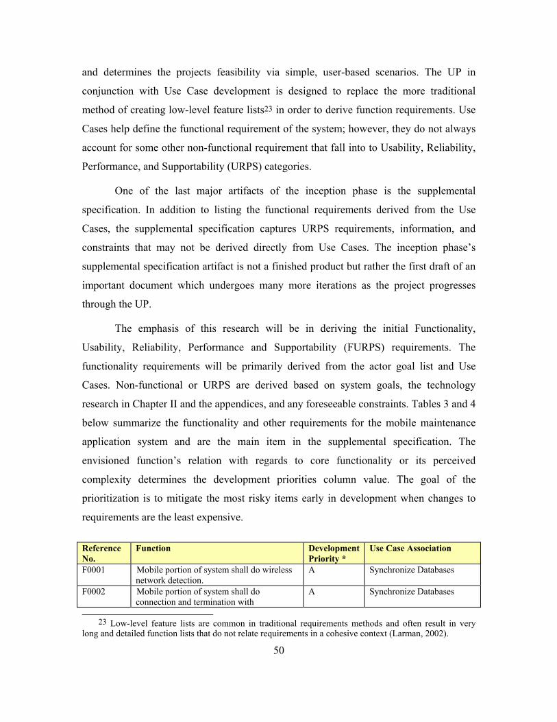
50
and determines the projects feasibility via simple, user-based scenarios. The UP in
conjunction with Use Case development is designed to replace the more traditional
method of creating low-level feature lists23 in order to derive function requirements. Use
Cases help define the functional requirement of the system; however, they do not always
account for some other non-functional requirement that fall into to Usability, Reliability,
Performance, and Supportability (URPS) categories.
One of the last major artifacts of the inception phase is the supplemental
specification. In addition to listing the functional requirements derived from the Use
Cases, the supplemental specification captures URPS requirements, information, and
constraints that may not be derived directly from Use Cases. The inception phase’s
supplemental specification artifact is not a finished product but rather the first draft of an
important document which undergoes many more iterations as the project progresses
through the UP.
The emphasis of this research will be in deriving the initial Functionality,
Usability, Reliability, Performance and Supportability (FURPS) requirements. The
functionality requirements will be primarily derived from the actor goal list and Use
Cases. Non-functional or URPS are derived based on system goals, the technology
research in Chapter II and the appendices, and any foreseeable constraints. Tables 3 and 4
below summarize the functionality and other requirements for the mobile maintenance
application system and are the main item in the supplemental specification. The
envisioned function’s relation with regards to core functionality or its perceived
complexity determines the development priorities column value. The goal of the
prioritization is to mitigate the most risky items early in development when changes to
requirements are the least expensive.
Reference No.
Function Development Priority *
Use Case Association
F0001 Mobile portion of system shall do wireless network detection.
A Synchronize Databases
F0002 Mobile portion of system shall do connection and termination with
A Synchronize Databases
23 Low-level feature lists are common in traditional requirements methods and often result in very
long and detailed function lists that do not relate requirements in a cohesive context (Larman, 2002).
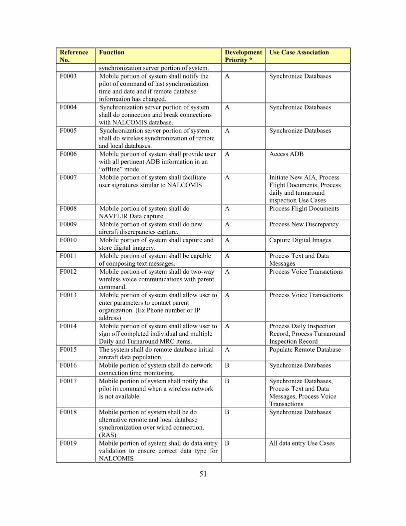
51
Reference No.
Function Development Priority *
Use Case Association
synchronization server portion of system. F0003 Mobile portion of system shall notify the
pilot of command of last synchronization time and date and if remote database information has changed.
A Synchronize Databases
F0004 Synchronization server portion of system shall do connection and break connections with NALCOMIS database.
A Synchronize Databases
F0005 Synchronization server portion of system shall do wireless synchronization of remote and local databases.
A Synchronize Databases
F0006 Mobile portion of system shall provide user with all pertinent ADB information in an “offline” mode.
A Access ADB
F0007 Mobile portion of system shall facilitate user signatures similar to NALCOMIS
A Initiate New AIA, Process Flight Documents, Process daily and turnaround inspection Use Cases
F0008 Mobile portion of system shall do NAVFLIR Data capture.
A Process Flight Documents
F0009 Mobile portion of system shall do new aircraft discrepancies capture.
A Process New Discrepancy
F0010 Mobile portion of system shall capture and store digital imagery.
A Capture Digital Images
F0011 Mobile portion of system shall be capable of composing text messages.
A Process Text and Data Messages
F0012 Mobile portion of system shall do two-way wireless voice communications with parent command.
A Process Voice Transactions
F0013 Mobile portion of system shall allow user to enter parameters to contact parent organization. (Ex Phone number or IP address)
A Process Voice Transactions
F0014 Mobile portion of system shall allow user to sign off completed individual and multiple Daily and Turnaround MRC items.
A Process Daily Inspection Record, Process Turnaround Inspection Record
F0015 The system shall do remote database initial aircraft data population.
A Populate Remote Database
F0016 Mobile portion of system shall do network connection time monitoring.
B Synchronize Databases
F0017 Mobile portion of system shall notify the pilot in command when a wireless network is not available.
B Synchronize Databases, Process Text and Data Messages, Process Voice Transactions
F0018 Mobile portion of system shall be do alternative remote and local database synchronization over wired connection. (RAS)
B Synchronize Databases
F0019 Mobile portion of system shall do data entry validation to ensure correct data type for NALCOMIS
B All data entry Use Cases

52
Reference No.
Function Development Priority *
Use Case Association
F0020 Mobile portion of system shall be capable and transmitting text messages over a wireless and wired network.
B Process Text and Data Messages
F0021 Mobile portion of system shall be capable of appending attachments to text messages.
B Process Text and Data Messages
F0022 Mobile portion of system shall allow user to access inspection MRCs in “offline” mode.
B Process Daily Inspection Record, Process Turnaround Inspection Record
F0023 System shall allow for easy management of users and passwords for mobile devices, and system access.
B Manage users
F0024 System shall be capable of secure operations over public networks using DoD accepted encryption standards that is centrally managed
B Manage Security
F0025 System shall be capable of over the air provisioning to facilitate security and configuration management of the mobile devices
B Manage Security, Manage Device Configuration
F0026 Mobile portion of system shall log all synchronization events.
C Synchronize Databases
F0027 Mobile portion of system shall log all connection durations.
C Synchronize Databases
F0028 Synchronization server portion logs all synchronization events.
C Synchronize Databases
F0029 Mobile portion of system shall be capable of storing multiple digital images.
C Capture Digital Images
* A= High design priority, B= Medium design priority, C= Lower design priority
Table 3. First Iteration Functional Requirements List.
Reference No.
Function *Category Detail and Constraints
O0001 The system should support multiple types of mobile devices
U Different aviation communities may require different devices for the identified users. Also allows the system to take advantage of improved technology when available
O0002 The mobile portion shall be ruggedized and capable of battery operations for up to 72 hours.
R The mobile device is expected to operate in a non-office type environment. Electrical outlets may not be available
O0003 The mobile device screen shall be readable in bright sunlight and at night
U The fielded device will be used primarily in outdoor flight line environment.
O0004 The mobile device software should be written once and support multiple types of device
S Many mobile studio packages support user centric approach
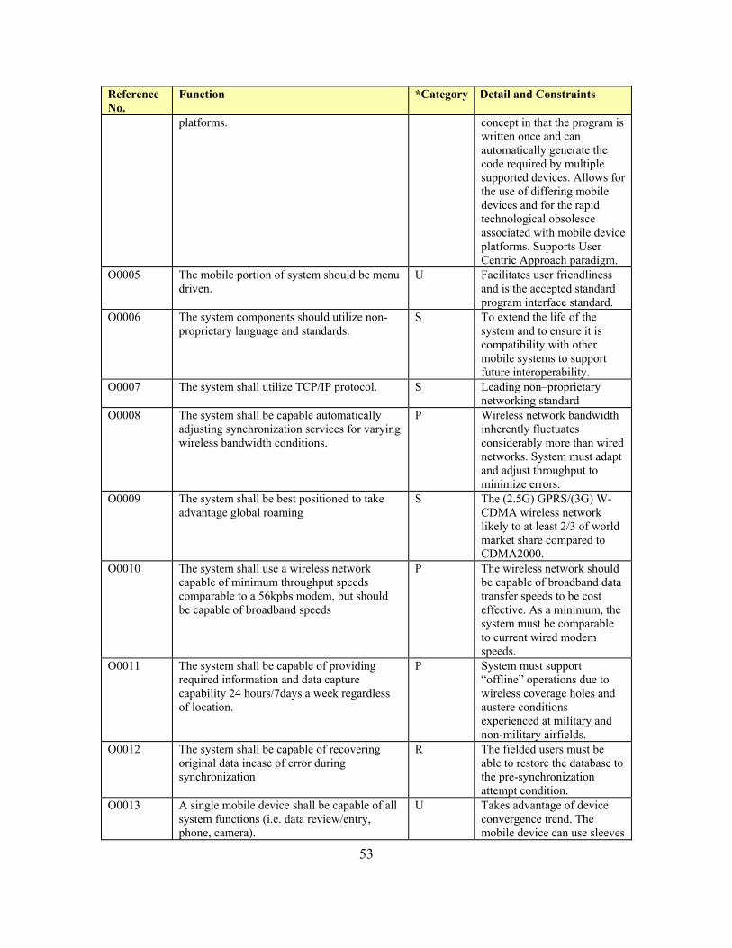
53
Reference No.
Function *Category Detail and Constraints
platforms. concept in that the program is written once and can automatically generate the code required by multiple supported devices. Allows for the use of differing mobile devices and for the rapid technological obsolesce associated with mobile device platforms. Supports User Centric Approach paradigm.
O0005 The mobile portion of system should be menu driven.
U Facilitates user friendliness and is the accepted standard program interface standard.
O0006 The system components should utilize non- proprietary language and standards.
S To extend the life of the system and to ensure it is compatibility with other mobile systems to support future interoperability.
O0007 The system shall utilize TCP/IP protocol. S Leading non–proprietary networking standard
O0008 The system shall be capable automatically adjusting synchronization services for varying wireless bandwidth conditions.
P Wireless network bandwidth inherently fluctuates considerably more than wired networks. System must adapt and adjust throughput to minimize errors.
O0009 The system shall be best positioned to take advantage global roaming
S The (2.5G) GPRS/(3G) W-CDMA wireless network likely to at least 2/3 of world market share compared to CDMA2000.
O0010 The system shall use a wireless network capable of minimum throughput speeds comparable to a 56kpbs modem, but should be capable of broadband speeds
P The wireless network should be capable of broadband data transfer speeds to be cost effective. As a minimum, the system must be comparable to current wired modem speeds.
O0011 The system shall be capable of providing required information and data capture capability 24 hours/7days a week regardless of location.
P System must support “offline” operations due to wireless coverage holes and austere conditions experienced at military and non-military airfields.
O0012 The system shall be capable of recovering original data incase of error during synchronization
R The fielded users must be able to restore the database to the pre-synchronization attempt condition.
O0013 A single mobile device shall be capable of all system functions (i.e. data review/entry, phone, camera).
U Takes advantage of device convergence trend. The mobile device can use sleeves

54
Reference No.
Function *Category Detail and Constraints
and adapters to meet requirements, however it must be auto configurable.
O0014 The mobile device shall be as small and light as possible for the given information requirements.
U Storage space in many types of aircraft is at a premium. Additionally, the austere environment of flight line operations is not optimized for larger mobile devices. PDA/ Smart phone recommended.
O0015 The mobile portion of the system should have a windows look and feel.
U The Navy employs windows based products, thus users are most comfortable using windows based products.
* U= Usability Requirement, R= Reliability Requirement, P= Performance Requirement, S= Supportability Requirement
Table 4. First Iteration of Non-Functional (URPS) Requirements List.
The FURPS tables derived above are the two major components of the
supplemental specification. By no means at this stage are they all-inclusive; however,
they provide the beginnings of a solid, user centric, requirements list that assists in
mapping system functionality to a specific user focused requirement specification.
As previously mentioned, the UP is highly iterative and every artifact derived to
this point will undergo many iterations in the elaboration phase where they are further
detailed and refined. Key Use Cases will eventually evolve into UML interaction
diagrams consisting of collaboration and system sequence diagrams, which aid in
understanding complex branching, iteration, concurrent behavior, and the sequence and
timing of messages. This process aids in making major design decisions.
D. SUMMARY
In review, the goal of the inception phase is to establish an initial common vision
for the aircrew mobile aircraft maintenance office application project and determine some
of the FURPS requirements which to better assess the feasibility of the project. Using the
artifacts derived above, developers and users begin to piece together some of the required
components, software functionality and networking technology that is required to bring

55
the system to fruition. It also provides the necessary information to determine if the
proposed system warrants a more serious investigative effort in the elaboration phase.
The artifacts produced from the inception phase of UP are also useful in
evaluating specific vendor mobile application development suites, hardware, and
networking solutions. The process yields an excellent base of functional and non-
functional requirements that serve as a checklist to better assess the vendor’s product and
its ability to meet the organization’s goals. The inception phase is designed to be
accomplished in a few days and does not involve heavy investment of capital. Most
importantly, Use Case generation within the UP framework supports the user centric
paradigm and is more likely to result in a system that maximizes the user experience. UP
involves users early, keeps the focus on the users goals, and is better positioned to
achieve user acceptance and “buy in” which is critical to system implementation.

56
THIS PAGE INTENTIONALLY LEFT BLANK
57
IV. CONCLUSION
A. CONCLUSIONS Based on the research conducted in Chapters II, III, and Appendices B and C the
aircraft mobile maintenance office project is a viable concept that adds value to the naval
aviation maintenance system. The research defined mobile business and identified an
implementation definition whose elements24, when combined, make the aircraft mobile
aircraft maintenance office plausible. Extending Optimized NALCOMIS, within the
larger framework of the Navy’s current WEN initiative, to mobile users serves as the e-
business and Internet components of the implementation definition. GPRS, CMDA2000,
and W-CDMA provide possible wide area wireless network solutions that promise
increased data speeds and enhanced wireless services to customers. Adopting the user
centric paradigm and employing the UP design approach in developing a mobile system
leads organizations to utilize scenario-based Use Cases to discover a common project
vision, mobile user processes, and the functional requirements of the system. Exercising
user-based scenarios to derive functional requirements in addition to the UP’s use of
iterative prototyping and user feedback mechanisms forces an organization to properly
engineer or re-engineer mobile application processes. It important to reiterate that process
re-engineering is probably the most critical component in positioning an m-business
initiative for successful implementation.
Improvements in mobile device computing power, memory storage, and battery
life extension capabilities improve the likelihood of mobile business adoption. These
mobile device improvements combined with the trend toward device convergence serve
as a positive multiplier in the mobile aircraft maintenance office system. Specifically, if
different functionality is modularized it affords the system added flexibility and
scalability. For example, mobile aircrew using a Hewlett Packard IPAQ h5450 PDA25
has enough computing power and memory to handle the mobile application and database 24 M-business = Process re-engineering + Internet + Wireless + E-business. 25 This device comes standard with Intel’s 400 MHz Xscale process, 64 Megabytes of Random Access
Memory and 48 Megabytes of Flash Read Only Memory. It also has a built in memory expansion slot for Secure Digital Memory Cards providing up to 128 Megabytes of additional memory space (HP iPAQ Pocket PC h5450, 2003).

58
requirements in addition to already having a built in mobile e-mail application and 802.11
wireless card. Additionally, the mobile device has the added flexibility of accepting
expansion packs that allow the device to integrate GPRS, W-CDMA, or CDMA2000
series wireless Compact Flash (CF) cards and serve as a digital camera.26 The above
described IPAQ, using Nexiam’s Nexicam camera expansion pack with a Sierra Wireless
GPRS wireless network card installed in the CF expansion slot, serves a mobile
computer, camera, and phone yet essentially maintains the footprint of a single device.
This type of modularity is a direct result of the device convergence trend and enables a
single device to meet the data, imagery, and voice requirements of the aircrew mobile
aircraft maintenance office.
Furthermore, this modular design has an added advantage in that it allows for
future developments without running the risk of complete device obsolescence. For
example, suppose the CDMA2000 3G standard is adopted for the mobile aircraft
maintenance office system based on its dominant market share in the United States.
While on deployment, a squadron sends two aircraft to an airbase in Italy to conduct low-
level navigation training flights for two days. Unfortunately, the 3G standard in Europe is
W-CDMA not CDMA2000 and the two 3G systems are not compatible (this is in spite of
the original ITU specification’s global roaming vision). All that is required to get the
system operational again is a quick swap out in the wireless CF card. The rest of the
system is unaffected. This scenario assumes the aircraft carrier has Internet capability and
that the Navy’s primary wireless carrier has partnered with European wireless carriers to
provide global coverage. Although the examples above used a Windows CE operating
system based device, other devices based on the Palm, Symbian, or Linux operating
systems also have similar modular expansion capabilities.
Another key finding was that mobile computing did not necessarily equate to
wireless computing. Many experts point out that organizations mistakenly plan or build
their mobile applications based on promised services of 3G wireless networks. To avoid
this mistake these experts recommend focusing on “mobile applications” versus “wireless
26 Sierra Wireless is one vendor who provides third party cellular network CF cards. Nexiam provides a digital camera expansion pack for the IPAQs and includes a slot that could accommodate a variety of CF cards to include wireless networking cards.

59
applications” in order to better position m-business initiatives. This argument in
conjunction with understanding that mobile computing includes both “online” and
“offline” models aids in better assessing high level functional requirements. Decision
makers are forced take a hard look into information requirements of the purposed system
to decide which mobile model is the most appropriate. With regard to the aircraft mobile
maintenance office, it becomes clear that there is no justifiable argument for the system
to be a “real time” system and that a “near real time” system will suffice. This discovery
greatly simplifies the problem, reduces the design costs, mitigates some of the wireless
and adaptable infrastructure risks, and makes for a truly mobile system.
The decision to use “offline” technology requires a “fat” mobile client in order to
process the replicated database data into the proper presentation and format for the
mobile users. This is opposed to a browser based “online” model using a “thin client” that
uses active server pages to query the database and provide the data in real time directly
from the server. Advantages in choosing the “offline” over the “online” include:
• Compensates for the holes in wireless network coverage.
• Reduces airtime costs to that required for synchronization.
• Allows for a truly mobile system that the end user can rely upon anytime and anywhere.
• Unlike an “online” system the “offline” model is not as dependent on the proposed 3G increased data rates in order to deliver a satisfactory user experience.
• “Offline” system infrastructure is less complex than “online” systems. “Offline” systems do not require complex XML/XSL transformation middleware to transform or convert existing web pages into a format optimized for the specific mobile device nor does it have to continually adjust content for existing network conditions.
The key advantage of the “offline” model is that it is not totally dependent on the
promised service and capabilities of 3G networks and can function in 2G or 2.5G
network environments. This allows naval aviation maintenance decision makers to
develop and deploy this system now while providing the necessary flexibility in case
cellular operators slow or abandon their efforts to deploy the expensive 3G upgrades.
60
Although the “offline” model offers a seemingly less complex infrastructure, it
still requires an intelligent synchronization server to synchronize the local and remote
databases. Additionally, the system may need to add a mobile server to handle such
administration functions as mobile user grouping, which facilitates user specific
information processing. This technology is still in the early stages of development.
Synchronization standards like SyncML appear to be in favor with some mobile
computing experts; however, the industry is still in its infancy and there is no clear-cut
predominant standard. Other disadvantages of the “offline” model include:
• The system is not “real time”. Critical information may not reach the mobile users or other stakeholders when needed.
• With regard to the WEN framework, “offline” database synchronization technology is not directly supported through the envisioned framework. The WEN framework is optimized for a wired “online” model.
• The mobile client device must be a more capable device in terms of memory and computing power to support “offline” operations.
• Mobile client software is more complex when compared to a browser based “online” client.
B. RECOMMENDATIONS It is recommended that the next generation NALCOMIS system designers adopt
the user centric paradigm and the UP design approach and expand on the products of
Chapter III. Specifically, the maintenance technician and maintenance supervisor mobile
aircraft maintenance office applications should be inducted into the inception phase of the
UP process and ultimately integrated into the products developed in Chapter III. By doing
so, next generation NALCOMIS users and developers can assess the viability of the total
mobile aircraft maintenance office project. If the result of the inception phase determines
the project warrants more investigation the project should move to the elaboration phase
of the UP.
The “offline” models lower total ownership cost, reduced technological risk, and
improved mobility makes it a more viable solution for the mobile aircraft maintenance
office application. This type of application inserts the necessary hooks within the WEN
61
framework to facilitate extending other DoD e-business initiatives, that may not be well
suited for the “online” model, to mobile business applications.
Lastly, designers should use commercially available mobile business development
suites to develop and implement the mobile aircraft maintenance office application.
Mobile computing technology is evolving at a rapid pace and choosing to develop the
system internally from within DoD could leave users with a less than optimal system in
terms in functionality, scalability, and interoperability. Products such a Sybase’s
iAnywhere or Covigo’s Enterprise Mobility solutions offer a full suite of solutions that
address the majority if not all of the major m-business development, implementation, and
management issues identified in this research. This recommendation also includes
commercially available mobile devices and operating systems. It is also important to
emphasize open versus proprietary standards to ensure future flexibility and scalability.
Organizations such as the Open Mobile Alliance27 serve as a venue to sponsor open
standards and interoperability. The alliance strives to focus industry efforts in the
direction of mobile service standardization, interoperable services across countries, and to
ensure operators and mobile devices meet user needs. Using commercially available
hardware and software solutions that support open standards should lead to a less
expensive system to develop, operate, and maintain and provide the necessary flexibility
and scalability required to deal with rapid and sometimes disruptive changes in mobile
technology.
C. FUTURE AREAS OF STUDY The primary focus of this research was exploring the mobile computing
technology landscape in order to generate the necessary artifacts to determine the
project’s feasibility and functional requirements. As the project progresses into the
elaboration phase, the need to explore specific areas related to the mobile technologies
and its vulnerabilities make for excellent topics for future thesis research. The topics
include:
27 The Open Mobile Alliance formed in June 2002 with over 200 company’s representing the world’s
leading mobile operators, device and network suppliers, information technology companies and content providers (Open Mobile Alliance Frequently Asked Questions, 2003).

62
• Explore the strengths and weaknesses of different database synchronization technologies as they apply to mobile applications.
• Identify the information security needs of mobile application and research suitable security mechanisms for the mobile devices and the data as it is transmitted over the air interface and public data networks.
• Perform an analysis of the information needs of fielded maintenance technicians and maintenance supervisors. Apply the results to properly match the correct mobile device to the specific user group’s information needs.
• Evaluate different commercial vendor’s mobile business development, implementation, and maintenance solutions to determine which best meets the mobile maintenance office requirements.
• Investigate the possibility of integrating the wide area mobile aircraft maintenance office application with a local area mobile application for flight line and hangar operations.
D. CONCLUDING COMMENTS The concluding comments section centers on the strengths of adopting a user-
centric approach, the UP system design methodology, and the importance of thorough
technology review. The user centric paradigm and UP combination keeps the user at the
forefront of all efforts and includes significant end user involvement throughout the
development process. The UP and the employment of Use Cases provides a simple
framework to quickly and easily develop a common vision, identify high level system
goals and constraints, define the system’s boundary, and develop scenario-based
functional requirements. This effort in combination with a thorough technology review
provides a foundation to adequately address other requirements and constraints to which
the system must conform. It also provides the IT manager with tools to evaluate
commercial vendor’s products with regard to a well-thought out and engineered m-
business initiative. Chapter III generated the first iteration of mobile project’s vision, Use
Case model, and supplementary specification and provides solid evidence that user
focused design approaches are the right methodology required to properly engineer a
mobile aircraft maintenance office application that has the best chance for
implementation success.

63
APPENDIX A. CELLULAR TECHNOLOGY BACKGROUND
A. INTRODUCTION Developments in modulation techniques and access methods combined with rapid
advances in microchip technology made wireless telephony feasible for public
consumption in the late 1970s. In the early 1990s analog cellular operators began the
migration to digital modulation schemes in order to address the shortcomings of the first
generation systems. The mid 1990’s witnessed the unforeseen explosion in public
Internet usage and marked the beginning of the Internet Age and the revolution in the
way people and organizations communicate and conduct business. Within the last five
years wireless technology has matured to the point it is no a longer fantasy to imagine a
world where mobile users can access the information they need anytime and anywhere.
Cellular technology has migrated from its humble beginnings as a circuit switched analog
voice communications networks to more reliable and secure digital modulation systems.
The migration is continuing and is currently introducing transitional technologies capable
of simultaneous digital voice and packet switched data services. The ultimate goal of
these new wireless cellular systems is to combine the Internet, telephones, and broadcast
media into a single device via Third Generation (3G) Cellular networks.
Currently, the true meaning 3G is obscured by different marketing terms. Further
complicating the issue is the fact the governing International Mobile
Telecommunications–2000 (IMT-2000) specification recognizes five different network
platforms as third generation systems. This appendix will detail the evolution of cellular
industry and introduce the basic concepts and capabilities as they pertain to the different
cellular networks leading to up to 3G. This historical foundation is necessary to better
understand the problems and issues surrounding 3G implementations.
B. EVOLUTION OF CELLULAR TECHNOLOGY
1. The Humble Beginnings Mobile telephony dates back to the 1920’s when several police departments in the
United States experimented with radiotelephony. The equipment was extremely bulky
64
and severely limited in channel capacity. These early experiments resulted in limited
success with maritime vessels; however, proved not particularly well suited for land use,
as radio technology did not deal well with buildings and other obstacles associated with
metropolitan environments.
The development of frequency modulation (FM) in the 1930s enabled
radiotelephony to network tactical units and their commanders on the battlefield during
World War II. Wartime radiotelephony developments carried over to peacetime and the
world saw limited mobile telephony service emerge in some large cities by the mid to late
1940’s (Smith & Collins, 2002). The primary method used to provide mobile telephone
service was similar to the methods used by broadcast radio and television. More simply
stated, the systems relied on a single transmitter placed on top of a tall building and
consisted of a finite number of channels. The limited channel capacity of these systems
rendered them unviable for commercial applications. Radio access, modulation
techniques, and microchip technology would have to evolve another thirty years before
mobile telephones and the supporting radio networks would reach the level suitable for
public acceptance.
2. First Generation Systems (1G) Emerging in the late 1970’s and earlier 80’s in the United States, Japan, and
Europe, mobile communications, as we know it today, finally became commercially
feasible. Based on purely analog transmission techniques, these 1G technologies mark the
genesis of the wireless network migration paths. The United States and Japan deployed
Advanced Mobile Phone Service (AMPS) operating in the 800 MHz cellular band while
the European’s deployed Nordic Mobile Telephony (NMT), operating in the 450 MHz
and later in the 900 MHz bands. In 1985, the British deployed a Total Access
Communications System (TACS) also operating in the 900 MHz band. Smith and Collins
(2002), describe TACS as nothing more than a modified version of AMPS. The Japanese
later adopted a modified version of TACS calling their system J-TACS. AMPS, NMT
and TACS are the predominant 1G systems and some are still in service today. Table 5
presents a summary of 1G analog cellular systems.
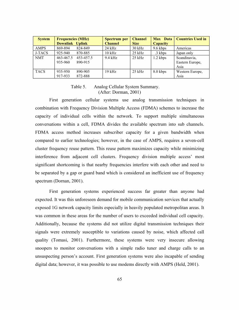
65
System Frequencies (MHz) Downlink Uplink
Spectrum per Channel
Channel Size
Max Data Capacity
Countries Used in
AMPS 869-894 824-849 24 kHz 30 kHz 9.6 kbps Americas J-TACS 925-940 870-885 10 kHz 25 kHz .3 kbps Japan only NMT 463-467.5 453-457.5
935-960 890-915 9.4 kHz 25 kHz 1.2 kbps Scandinavia,
Eastern Europe, Asia
TACS 935-950 890-905 917-933 872-888
19 kHz 25 kHz 8.0 kbps Western Europe, Asia
Table 5. Analog Cellular System Summary.
(After: Dorman, 2001)
First generation cellular systems use analog transmission techniques in
combination with Frequency Division Multiple Access (FDMA) schemes to increase the
capacity of individual cells within the network. To support multiple simultaneous
conversations within a cell, FDMA divides the available spectrum into sub channels.
FDMA access method increases subscriber capacity for a given bandwidth when
compared to earlier technologies; however, in the case of AMPS, requires a seven-cell
cluster frequency reuse pattern. This reuse pattern maximizes capacity while minimizing
interference from adjacent cell clusters. Frequency division multiple access’ most
significant shortcoming is that nearby frequencies interfere with each other and need to
be separated by a gap or guard band which is considered an inefficient use of frequency
spectrum (Dornan, 2001).
First generation systems experienced success far greater than anyone had
expected. It was this unforeseen demand for mobile communication services that actually
exposed 1G network capacity limits especially in heavily populated metropolitan areas. It
was common in these areas for the number of users to exceeded individual cell capacity.
Additionally, because the systems did not utilize digital transmission techniques their
signals were extremely susceptible to variations caused by noise, which affected call
quality (Tomasi, 2001). Furthermore, these systems were very insecure allowing
snoopers to monitor conversations with a simple radio tuner and charge calls to an
unsuspecting person’s account. First generation systems were also incapable of sending
digital data; however, it was possible to use modems directly with AMPS (Held, 2001).

66
Despite these shortcomings, Smith and Collins (2002) feel it was the introduction
of first generation systems that began the wireless revolution toward mobile
telecommunications being an accepted and expected method of communication. The
shortcomings in 1G capacity, interference, security, and digital data incapability became
the primary drivers for wireless research as engineers charted the migration path to the
second generation of cellular technologies.
3. Second Generation Systems (2G) In response to the inherent weaknesses associated with analog 1G systems, second
generation (2G) systems employed digital transmission methods. These digital systems
have a number of advantages, including greater capacity, increased security against fraud,
encryption, and are capable of more advanced services such as simple text messaging,
voice mail, and caller ID.
Second generation systems consist of various types of technologies. The three
most successful systems deployed are Global System for Mobile communications
(GSM), D-AMPS 1900, sometimes referred to as Interim Standard-136 (IS-136), and IS-
95 referred to as cdmaOne. Dividing these three 2G platforms into two categories based
on access technologies employed, Time Division Multiple Access (TDMA) or Code
Division Multiple Access (CDMA), ones sees the nexus of the diverging evolutionary
paths toward 3G.
a. Time Division Multiplex Accessing Systems Both D-AMPS 1900 and GSM employ TDMA technology to allow
multiple users to occupy the same sub channel on a time-sharing basis. The resulting
increase in the capacity of an individual cell is proportional to the number of time slots
allotted per sub channel. D-AMPS 1900 divides each channel into six slots with each user
requiring two time slots, whereas GSM subdivides each channel into eight slots, each
supporting a single user. A TDMA platform that allocates seven time slots per channel
realizes seven times more capacity within a cell over a 1G FDMA system. TDMA offers
three other advantages. First, it reduces interference from other simultaneous
transmission since users are separated by time. Secondly, it extends battery and talk time
of the Mobile Terminal Set (MTS) since it is only transmitting during the assigned time

67
slot. Lastly, when a TDMA frame is both channelized and divided into sub channels,
services such as paging and short messages become possible (Gil Held, 2001, p. 67).
b. Code Division Multiple Accessing Systems CdmaOne uses CDMA technology. In CDMA there is no restriction on
time or bandwidth in that the transmitter may transmit whenever it wishes and can use
any or all the bandwidth allocated to the system or channel (Tomasi, 2001). CdmaOne
takes advantage of spread spectrum technology and employs the Direct Sequence Spread
Spectrum (DSSS) technique for the spreading function. CDMA neither divides the time
nor frequency domains; instead, all CDMA users share the same frequency at the same
time. It is obvious this technique causes all users to interfere with each other. Modulating
each user’s signal with a unique psuedonoise (PN) digital signal to spread the signal over
a wide bandwidth overcomes this interference problem. The PN signal actually represents
a code of chips, where chips refer to small data bits in the PN code. To illustrate the
concept of chipping and how it artificially increases the data rate and bandwidth, assume
three sub-bits, called chips, replace each bit of the original signal. The resulting
multiplication process yields three chips for every original bit thus, increasing the data
rate and bandwidth by three.
The PN code bit rate is significantly faster when compared to the bit rate
of the original information. A replica of the PN code is available at the receiver, which
allows the receiver to isolate the sequence of interest from all the other signals present,
which appears as background noise. This technique enables a large number of CDMA
signals to share the same frequency spectrum. Gil Held (2001) states,
Because frequency changes over time, CDMA can be considered to represent a combination of FDMA and TDMA. That is, transmission can commence at frequency f1 for period t1, then move to f2 for period t2, and so on” (p. 117).
Comparing CDMA to TDMA and FDMA, CDMA appears to require
more bandwidth per channel than other technologies; however, the bandwidth is shared
by many users simultaneously and thus uses the spectrum more efficiently (Dornan,
2001). Additionally, CDMA systems operate with a lower signal to noise ratio while
maintaining a given channel capacity and benefit from increased cell and system
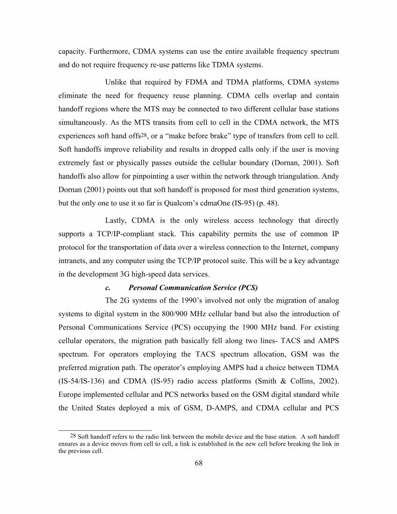
68
capacity. Furthermore, CDMA systems can use the entire available frequency spectrum
and do not require frequency re-use patterns like TDMA systems.
Unlike that required by FDMA and TDMA platforms, CDMA systems
eliminate the need for frequency reuse planning. CDMA cells overlap and contain
handoff regions where the MTS may be connected to two different cellular base stations
simultaneously. As the MTS transits from cell to cell in the CDMA network, the MTS
experiences soft hand offs28, or a “make before brake” type of transfers from cell to cell.
Soft handoffs improve reliability and results in dropped calls only if the user is moving
extremely fast or physically passes outside the cellular boundary (Dornan, 2001). Soft
handoffs also allow for pinpointing a user within the network through triangulation. Andy
Dornan (2001) points out that soft handoff is proposed for most third generation systems,
but the only one to use it so far is Qualcom’s cdmaOne (IS-95) (p. 48).
Lastly, CDMA is the only wireless access technology that directly
supports a TCP/IP-compliant stack. This capability permits the use of common IP
protocol for the transportation of data over a wireless connection to the Internet, company
intranets, and any computer using the TCP/IP protocol suite. This will be a key advantage
in the development 3G high-speed data services.
c. Personal Communication Service (PCS) The 2G systems of the 1990’s involved not only the migration of analog
systems to digital system in the 800/900 MHz cellular band but also the introduction of
Personal Communications Service (PCS) occupying the 1900 MHz band. For existing
cellular operators, the migration path basically fell along two lines- TACS and AMPS
spectrum. For operators employing the TACS spectrum allocation, GSM was the
preferred migration path. The operator’s employing AMPS had a choice between TDMA
(IS-54/IS-136) and CDMA (IS-95) radio access platforms (Smith & Collins, 2002).
Europe implemented cellular and PCS networks based on the GSM digital standard while
the United States deployed a mix of GSM, D-AMPS, and CDMA cellular and PCS
28 Soft handoff refers to the radio link between the mobile device and the base station. A soft handoff
ensures as a device moves from cell to cell, a link is established in the new cell before breaking the link in the previous cell.
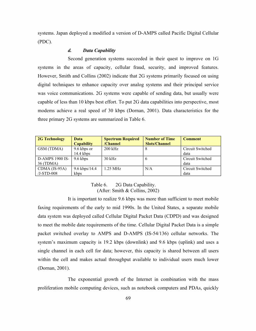
69
systems. Japan deployed a modified a version of D-AMPS called Pacific Digital Cellular
(PDC).
d. Data Capability Second generation systems succeeded in their quest to improve on 1G
systems in the areas of capacity, cellular fraud, security, and improved features.
However, Smith and Collins (2002) indicate that 2G systems primarily focused on using
digital techniques to enhance capacity over analog systems and their principal service
was voice communications. 2G systems were capable of sending data, but usually were
capable of less than 10 kbps best effort. To put 2G data capabilities into perspective, most
modems achieve a real speed of 30 kbps (Dornan, 2001). Data characteristics for the
three primary 2G systems are summarized in Table 6.
2G Technology Data Capability
Spectrum Required /Channel
Number of Time Slots/Channel
Comment
GSM (TDMA) 9.6 kbps or 14.4 kbps
200 kHz 8 Circuit Switched data
D-AMPS 1900 IS-36 (TDMA)
9.6 kbps 30 kHz 6 Circuit Switched data
CDMA (IS-95A) /J-STD-008
9.6 kbps/14.4 kbps
1.25 MHz N/A Circuit Switched data
Table 6. 2G Data Capability.
(After: Smith & Collins, 2002)
It is important to realize 9.6 kbps was more than sufficient to meet mobile
faxing requirements of the early to mid 1990s. In the United States, a separate mobile
data system was deployed called Cellular Digital Packet Data (CDPD) and was designed
to meet the mobile date requirements of the time. Cellular Digital Packet Data is a simple
packet switched overlay to AMPS and D-AMPS (IS-54/136) cellular networks. The
system’s maximum capacity is 19.2 kbps (downlink) and 9.6 kbps (uplink) and uses a
single channel in each cell for data; however, this capacity is shared between all users
within the cell and makes actual throughput available to individual users much lower
(Dornan, 2001).
The exponential growth of the Internet in combination with the mass
proliferation mobile computing devices, such as notebook computers and PDAs, quickly

70
proved 2G data service rates to be inadequate to support modern applications.
Researchers saw this need coming and began plotting a migration path to 3G wireless
technologies via the IMT-2000 specification. Because of market risk, upgrade costs, and
the requirement to be backwards compatible with existing 2G networks, operators would
need to phase in new services outlined by the IMT-2000 specification for 3G systems.
This resulted in development of 2.5 Generation (2.5G) transitional technologies to allow
operators possessing cellular, PCS, or Universal Mobile Telecommunications System
(UMTS) spectrum to deploy digital packet services prior to the availability of 3G
platforms (Smith & Collins, 2002).
4. Two Point Five Generation Systems (2.5G) Smith and Collins (2002) define 2.5G as “the method or methodology from which
existing cellular and Personal Communications Service (PCS) operators are migrating to
the next generation wireless technology referenced in the International Mobile
Telecommunications-2000 (IMT-2000) specification” (p. 166). These 2.5G transitional
technologies are primarily concerned with increasing data speeds above 2G’s meager
14.4 kbps to at least that of fast modems. The key 2.5G platforms are as follows:
• General Packet Radio Service (GPRS)
• Enhanced Data Rates for Global Evolution (EDGE)
• Code Division Multiple Access 2000 (CDMA2000 1xRTT)
a. General Packet Radio Service (GPRS) GPRS systems provide packet data at higher speeds than those available
over standard GSM circuit switched data services. Originally conceived as an upgrade for
any TDMA-based system, GPRS has proved to effectively work with only GSM systems
(Dornan, 2001). Utilizing the same 200 kHz channels and eight time slots per carrier
allows the GPRS air interface to share GSM’s RF resources.
GPRS achieves greater speeds over the same basic GSM air interface
through the use multiple time slots. Although never realized in operational networks, the
GPRS air interface is capable of theoretical speeds up to 171 kbps. The practical
maximum is 115.2 kbps, with realistic speeds of about 40 kbps or 53 kbps (Smith &
Collins, 2002). The channel coding of GPRS is different than that of GSM and allows for
71
different data rates per time slot. GPRS networks using Coding Scheme 2 (CS-2), which
allows for 13.4 kbps per time slot, can provide user rates of 40.2 kbps or 53 kbps
assuming the subscriber has access to three or four time slots respectively.
GPRS’s biggest advantage is that it employs packet switched technology.
Unlike circuit switched systems where a connection is maintained regardless of whether
data is being transmitted, the packet switched system consumes RF resources only at the
instant that data is being sent or received. When a MTS is not sending data, another MTS
set can use the time slots on the air interface. This procedure requires a request-allocation
process between the MTS and the network whenever a user’s MTS needs to send data.
The user perceives the GPRS system as “always connected” to the network as the
aforementioned procedure is transparent and happens quickly enough to appear “always-
on” (Smith & Collins, 2002).
b. Enhanced Data Rates for Global Evolution (EDGE) Originally, EDGE stood for “Enhance Data Rates for GSM Evolution”;
however, shortly after being proposed, the technology received a recommendation
suggesting it as a possible migration path for IS-36 TDMA network evolution too. This
proposal precipitated the switch from “GSM” to “Global” in the acronym. Smith and
Collins (2002) and Dornan (2001) both point out EDGE inherited almost all of its main
features and network elements including interfaces, protocols, and access procedures
from GPRS. The basic goal of EDGE is to complement GSM/GPRS networks in order to
increase data throughput rates above that which is possible via GPRS alone.
Like GSM/GPRS, EDGE operates using the same 200 kHz, eight time slot
TDMA channels; however, it uses Eight Phase Shift Keying (8-PSK) versus .3 Gaussian
Minimum Shift Keying (GMSK) as the air interface modulation scheme. The advantage
of this modulation change lies in the fact that 8-PSK offers approximately a 3:1 increase
in bandwidth efficiency over the .3 GMSK scheme employed by GSM (Tomasi, 2001).
Using the 8-PSK-air interface modulation scheme, EDGE networks theoretically support
speeds up to 384 kbps. The increased bandwidth efficiency and resulting increase in
throughput comes at the expense of additional hardware costs required to support 8-PSK

72
modulation, increased bit error rates due to 8-PSK’s greater sensitivity to noise, and in
smaller individual cell foot prints.
The Shosteck Group (2001) point out in a white paper that the deployment
of EDGE by either a GSM or D-AMPS 1900 operator would be more than just a software
upgrade. The paper suggests the EDGE upgrade may require additional hardware
subsystems of cell cites, changes in frequency reuse patterns, and implies changes in base
station antennas. Additionally, since the cell footprint associated with 8-PSK is smaller
than for GMSK, more base stations may be required (Smith & Collins, 2002). Lastly, the
user’s MTS would have to support all three modes of operation - GSM, GPRS and
EDGE. It is because of the above reasons, the Shosteck Group (2001) concludes, “For
such reasons, the implementation of EDGE may be more complex than some may have
initially envisioned” (p. 16). Smith & Collins (2002) support the Shosteck conclusion
when they state, “ It remains to be seen whether EDGE will be widely deployed as
pseudo-3G system, as a stepping stone toward UMTS, or whether operators will decide to
leapfrog EDGE and move directly from GPRS to UMTS” (p. 196).
c. Code Division Multiple Access2000 (CDMA2000 1xRTT) The CDMA2000 One Times Radio Transmission Technology (1xRTT),
referred to a phase one or (1X) of the 3G-migration path from cdmaOne to CDMA2000,
is a predominantly non-European platform transitioning cdmaOne (IS-95 A/B) voice
systems to high-speed packet data networks capable data rates of 144 kbps. This
transition technology capitalizes on existing cdmaOne radio base stations and spectrum
allocations and is fully backward compatible with the cdmaOne infrastructure and
subscriber units (Smith & Collins, 2002). Additionally, phase one supports all of the
cdmaOne’s voice, circuit switched data, Short Message Service (SMS), and over the air
provisioning and activation services. It also supports handoffs with cdmaOne systems and
uses both common carriers as well as new carriers (Smith & Collins, 2002). CDMA2000
is backward compatible with existing 2G cdmaOne systems allowing for less expensive,
phased oriented upgrades and changes from a fixed network perspective.
The CDMA2000 1X architecture is essentially the same as that used for
IS-95 systems; however, still requires new components and upgrades to the existing 2G-

73
network. The upgrades include new element cards in the Base Station Transceiver (BTS)
and Base Station Controllers (BSC) in combination with a few new data network
components and improved vocoders to handle the packet switched data sessions. Phase
one uses the same 1.25 MHz channel bandwidth as IS-95 systems. However, the
upgraded system uses improved vocoders and 128 Walsh codes, as compared to sixty-
four in cdmaOne, to achieve higher data rates and greater voice capacity (Smith &
Collins, 2002).
CDMA2000 1xRTT is a logical migration path for cdmaOne operators just
as GPRS and EDGE is for TDMA operators since each makes use of existing network
infrastructure. However D-AMPS (IS-36) operators must make a choice either to go
towards GSM/GPRS/EDGE route, proceed direct to Wideband-CDMA (W-CDMA), also
referred to as UMTS, or switch to CDMA2000. Figure 4 summarizes the linkages
between various platforms the migration path from 1G to 3G.
Figure 4. 3G Migration Paths of Various Platforms. (From: Smith & Collins, 2002, p. 139)

74
THIS PAGE INTENTIONALLY LEFT BLANK
75
APPENDIX B. INTERNATIONAL MOBILE TELECOMMUNICATION-2000 STANDARD
A. THIRD GENERATION DEFINED The dramatic growth in the wireless market due to the success of 2G digital
cellular and PCS networks led to the demand for new features and more efficient
services. In 1992, the ITU defined the standard for the UMTS system via the IMT-2000
specification. The specification calls for high-speed broadband data services,
simultaneous voice and data capability, referred to as multimedia support, improved
system efficiency to reduce costs, and backward compatibility with 2G systems. The
IMT-2000 specification envisions UMTS as a universal or global service and requires the
cooperation of many leading standard committees across the globe to develop such
systems. Currently, the IMT-2000 standard organization is delegating the responsibility
of 3G-platform development to two international partnerships: Third Generation
Partnership Program (3GPP) and the Third Generation Partnership Program 2 (3GPP2).
The 3GPP organization is responsible for coordinating the international effort for the W-
CDMA standard based on backward compatibility with GSM and IS-136/PDC, while the
3GPP2 coordinates the CDMA2000 standard based on backward compatibility with the
cdmaOne.
The primary focus of the IMT-2000 specification is to increase data rates of
wireless networks. Originally, three different data rates where established, each
corresponding to the B, H, and P-rate Integrated Services Digital Network (ISDN) lines
for fixed carriers’ core voice networks (Dornan, 2001, p. 102). More specifically, IMT-
2000 specifies 3G networks shall be capable of 144 kbps, 384 kbps, and 2 Mbps for
vehicular, pedestrian, and indoor fixed wireless applications respectively. The
specification also includes variable data rates for large geographic coverage areas via
satellite systems. As the Internet’s popularity exploded in both the commercial and
private markets, the ITU realized that “Surfing the Web” would become one of 3G’s
most important applications. Foreseeing the demand for the Web, the ITU added the
additional requirement to the IMT-2000 specification mandating support for Internet

76
protocols and that 3G network backbones be packet switched. The change did not alter
the above mentioned data rate requirement but did make the circuit switched ISDN
concept obsolete.
The key goal of IMT-2000 specification is to combine the Internet, telephones,
and broadcast media into single device. To do so, IMT-2000 systems must deliver six
broad classes of services - interactive media, high multimedia, medium multimedia,
switched data, simple messaging, and speech. Table 7 depicts the data rates, level of
asymmetry, and switching modes for these six services.
Service Classification
Upstream Data Rate
Downstream Data Rate
Asymmetry Factor
Example Switch
Interactive Multimedia
256 kbps 256 kbps Symmetric Videoconferencing Circuit
High Multimedia 20 kbps 2 Mbps 100 Television Packet Medium Multimedia
19.2 kbps 768 kbps 40 Web Surfing Packet
Switched Data 43.2 kbps 43.2 kbps Symmetric Fax Circuit Simple Messaging
28.8 kbps 28.8 kbps Symmetric Email Packet
Speech 28.8 kbps 28.8 kbps Symmetric Telephony Circuit
Table 7. Service Types Available Over IMT-2000 29 (From: Dornan, 2002, p.105)
Theodore Rappaport (2002) states,
3G systems promise unparalleled wireless access in ways that have never been possible before. Multi-megabit Internet access, communication using Voice over Internet Protocol (VoIP), voice activated calls, unparalleled network capacity, and ubiquitous “always on” access are just some of the advantages being touted by 3G developers (p. 34).
However, contrary to Rapport’s statement, many critics point out how expected
3G services are over hyped by extremely optimistic marketers and have led to the
somewhat disappointing performance reviews surrounding 3G network introduction.
29 Virtual circuits will likely replace physical circuits where the table indicates circuit switching is required (Dornan, 2002).

77
B. IMT–2000 SPECTRUM The IMT-2000 specification originally suggested a global spectrum centered
about the 2000 MHz region in order facilitate global roaming especially if using the same
IMT-2000 platform. Dornan (2001) explains that Europe and many Asian countries set
aside the ITM-2000 spectrum, with China being the only country that followed ITU’s
recommendation exactly. Europeans and Japanese were using portions of the designated
spectrum for cordless phones and GSM and America had already used the entire
recommended spectrum for its PCS or fixed wireless system. The only part of the 3G
recommended spectrum that is still available worldwide is that earmarked for 3G satellite
services. Analysts doubt that the world will ever see satellites capable of mobile
operations of 144 kbps since broadband satellites need much higher frequencies to be
effective (Dornan, 2001). With above argument in place, Dornan (2001) notes that many
industry leaders suggest releasing the Mobile Satellite Service (MSS) spectrum for
Cellular IMT-2000. Figure 5 summarizes the spectrum allocation for 3G cellular and
MSS in major world economies.
Figure 5. Spectrum Allocation for 3G Cellular and MSS in Major World Economies. (From: Dornan, 2001, p. 107)

78
Currently, countries around the globe are attempting to identify new radio
spectrum bands to accommodate the deployment of 3G networks expected in the 2004 -
2005 time frame. During its 2000 World Radio Conference, the ITU recommended the
2500-2690 MHz, 1710-1885 MHz, and 806-960 MHz bands as candidates for 3G. In the
United States, spectrum in the upper UHF television bands near 700 MHz is being
considered for 3G; however, given the economic slowdown of the television
communications industry during 2001 many governments including the U.S. decided to
postpone 3G auctions and spectrum decisions as of late 2001 (Rappaport, 2001). On July
23, 2002, the Federal Communication Commission, Department of Commerce, and
Department of Defense agreed to release 90 MHz of spectrum for use by 3G services
located between 1710-1755 MHz and 2110-2155 MHz. Third generation service
providers can expect the new 90 MHz of spectrum to be available no later than 2008
(Department of Commerce, 2002).
C. SYSTEM INTER-COMPATIBILITY Originally, the ITU envisioned UMTS as a brand new system. However, in 1996
this viewpoint changed allowing existing 2G networks to integrate with the UMTS
services. Harte, Levine, and Kikta (2002) emphasize the significance of this change when
they state, “This is very important as it allows existing wireless operators to cost
effectively upgrade their systems and network equipment manufacturers to offer existing
field-proven equipment to new operations without having to invest billions of dollars into
research and new product development” (p. 21-22).
This change not only improved the cost feasibility of introducing 3G services, it
facilitated the achievement of backward compatibility with existing 2G-system
requirement. However, this change exacerbated the divergence in platform technologies
as we move towards 3G and with the spectral issues mentioned above may lead to
compromises in intersystem compatibility.
European and Japanese 3G deployment efforts focus on W-CDMA technology, as
previously is also referred to as UMTS, while American and Korean efforts center around
the CDMA2000 standards. It is important to note that North America has both cdmaOne

79
and GSM nationwide 2G systems; hence, U.S. wireless operators are deploying either W-
CDMA or CDMA2000 systems based on their existing 2G-network platform access
technology. Also adding to confusion is the divergence of 3G technologies as the IMT-
2000 specification currently recognizes five different radio access platforms. Figure 6
depicts the different platforms comprising the IMT-2000 specification and their
respective 2G access migration paths
Figure 6. IMT-2000 Radio Access Platforms (From: Smith & Collins, 2002, p. 137)
The above discussion concerning the various 3G migration paths and the IMT-
2000 specification explains some of the confusion surrounding 3G systems and is
supported by Smith and Collins (2002) when they state, “The radio access platforms that
comprise the IMT-2000 specification are all different and it should be no wonder that is
difficult to obtain a simple answer when asked to describe what a 3G system looks like”
(p. 137). However, in 1999 a meeting of the International Telecommunications Union
(ITU) group of radio experts endorsed harmonization for the CDMA component of the
IMT-2000 standard. Gil Held (2001) explains, “The harmonization parameters for
CDMA are structured to develop inexpensive multimode phones, which should enable
W-CDMA and CDMA2000 phones to interoperate” (p. 141).

80
THIS PAGE INTENTIONALLY LEFT BLANK

81
APPENDIX C. THIRD GENERATION TECHNOLOGY OVERVIEW
A. INTRODUCTION The two predominant system standards for third generation wireless systems are
W-CDMA and CDMA-2000. Both technologies encompass Frequency Division Duplex
(FDD) and Time Division Duplex (TDD) systems each optimized for a particular
environment. W-CDMA is the most logical progressions for GSM and IS-36 TDMA
operators while CDMA2000 is the most logical for cdmaOne (IS-95) operators. The
following discussion will focus primarily on the data aspects of the W-CDMA and
CDMA2000 3G platforms as it pertains to theory, capacity, operation, and data rates.
1. Wideband Code Division Multiple Access (W-CDMA)
a. System Theory and Concepts W-CDMA technology is a wideband spread spectrum technology that will
replace GSM/IS-36/GPRS/EDGE 2.5G networks. Currently wireless operators in Europe,
Japan and the United States are deploying or migrating towards the W-CDMA standard.
The W-CDMA system utilizes paired 5 MHz FDD channels, efficient coding, and the
capability to combine multiple traffic channels to provide low speed circuit switched and
high-speed packet switched services. The standard employs direct sequence code division
multiple access technology, Quadrature Modulation Phase Shift Keying (QPSK)
modulation, and variable bandwidth control. Unlike the IS-95 CDMA systems described
earlier, W-CDMA uses up to 256 (uplink) and 512 (downlink) spreading and
channelization codes to vary bandwidth and achieve multiple channels within the same
frequency band. W-CDMA can dynamically change it spreading codes to provide
Bandwidth on Demand (BoD) services by changing the number of chips representing
each bit of information.
A W-CDMA system uses a single type of radio channel to transfer voice,
data, and control information. It does this by dividing the radio channel into overlapping
physical and logical, also referred to as transport, channels. Unique channel codes
identify the different physical channels while frame and field formats comprise the
logical channels. A basic channel consists of 10 msec frames comprised of 15 times slot
82
bursts each lasting 666 usecs. Within a frame, a user is an assigned one or more timeslots
bursts for reception and specific corresponding burst for transmission. It is important to
note, that within a frame there are usually several time slots that remain idle. The MTS
use the idle time slots to measure the signal strength of surrounding cell carrier channels.
The idle listening assists in channel selection and handoff.
The FDD W-CDMA system uses two 5 MHz carriers- one for downlink or
forward carrier (cell site to MTS) and one for uplink or reverse carrier (MTS to cell site).
To simplify the design of the MTS, W-CDMA systems are not full duplex systems and
do not transmit and receive at the same time. Harte, Levine, and Kikta (2002) explain that
in order to emulate full duplex operations during voice conversations the system takes the
compressed speech bursts and expands them in time to create a continuous audio signal.
W-CDMA uses several types of digital control channels in conjunction
with digital traffic channels for each carrier. The digital control channels of W-CDMA
are capable of coordinating multimedia, high-speed packet data, broadcast messaging,
and fast power control and are considered superior to those of 2G GSM systems (Harte,
Levine & Kikta, 2002). Unique spreading channelization codes allow control and traffic
channels coexist on the same carrier frequency.
W-CDMA systems support asynchronous data transfer by incorporating
variable spreading codes and time slot sharing. In theory, using different spreading
factors, defined as the ratio of chip rate to the user data symbol rate, each down link and
uplink channel is capable of 1920 kbps and 960 kbps respectively. However, in reality
W-CDMA produces net data rates of up to 936 kbps for each downlink channel and up to
480 kbps for each uplink channel. The difference between the theoretical and net data
rates is due to the addition of ½ convolution coding error protection and overhead
signaling information for downlink channel and error protection on the uplink channel
(Harte, Levine & Kikta, 2002).
The modulation techniques employed by the downlink and uplink
channels explains W-CDMA’s asynchronous data rates. The downlink channel uses
QPSK modulation, which generates one symbol for every two input bits whereas the
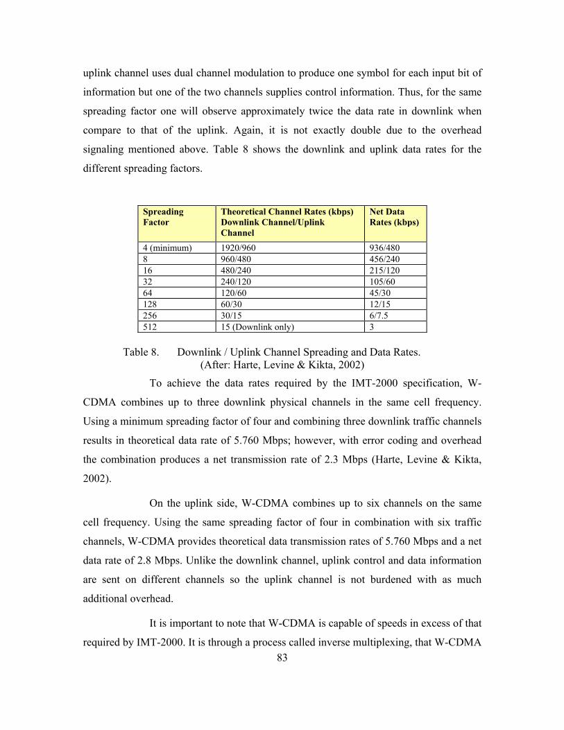
83
uplink channel uses dual channel modulation to produce one symbol for each input bit of
information but one of the two channels supplies control information. Thus, for the same
spreading factor one will observe approximately twice the data rate in downlink when
compare to that of the uplink. Again, it is not exactly double due to the overhead
signaling mentioned above. Table 8 shows the downlink and uplink data rates for the
different spreading factors.
Spreading Factor
Theoretical Channel Rates (kbps) Downlink Channel/Uplink Channel
Net Data Rates (kbps)
4 (minimum) 1920/960 936/480 8 960/480 456/240 16 480/240 215/120 32 240/120 105/60 64 120/60 45/30 128 60/30 12/15 256 30/15 6/7.5 512 15 (Downlink only) 3
Table 8. Downlink / Uplink Channel Spreading and Data Rates.
(After: Harte, Levine & Kikta, 2002)
To achieve the data rates required by the IMT-2000 specification, W-
CDMA combines up to three downlink physical channels in the same cell frequency.
Using a minimum spreading factor of four and combining three downlink traffic channels
results in theoretical data rate of 5.760 Mbps; however, with error coding and overhead
the combination produces a net transmission rate of 2.3 Mbps (Harte, Levine & Kikta,
2002).
On the uplink side, W-CDMA combines up to six channels on the same
cell frequency. Using the same spreading factor of four in combination with six traffic
channels, W-CDMA provides theoretical data transmission rates of 5.760 Mbps and a net
data rate of 2.8 Mbps. Unlike the downlink channel, uplink control and data information
are sent on different channels so the uplink channel is not burdened with as much
additional overhead.
It is important to note that W-CDMA is capable of speeds in excess of that
required by IMT-2000. It is through a process called inverse multiplexing, that W-CDMA
84
combines multiple physical channel codes to achieve data rates in excess 2 Mbps. In
essence, the system coordinates the data supplied to each channel and transmits a control
message that identifies how the independent physical channels and their associated
logical channels are combined or divided (Harte, Levine & Kikta, 2002, p. 301).
The mobility Quality of Service (QoS) requirement for 384 kbps at
pedestrian speeds and 144 kbps at vehicular speeds are a function of the spreading factor
required to maintain adequate error control. This BoD, suggests the faster the user is
moving the greater the spreading factor, the greater the number of times a single bit is
chipped to improve the gain, thus the lower data rates achievable.
It is important to understand that spreading factor is not the same as the
channelization code; however, there is a correlation between them. The channelization
code uniquely identifies each physical channel among other channels using the same
frequency and does not alter amount of spreading of a given signal. However,
channelization codes have a hierarchical structure where low level codes (high spread
factors) are subsets of high level code (low spread factor) codes. This means that if a user
has a demand for a high rate packet data session, requiring a minimum spread factor of 4
and thus requiring the highest level channel code, the lower level codes are not available.
This essentially means that as the data requirements in a cell increase, the number of
available channels decrease, thus limiting the cell’s subscriber capacity.
b. System Architecture The W-CDMA system includes many of the same basic subsystem
components as the 2 and 2.5G wireless systems it replaced. Smith and Collins (2002)
explain that W-CDMA borrows heavily from the established GSM/GPRS network
architecture and reuses many of the components of the existing 2.5G systems. However,
the Radio Access Network (RAN) portion, referred to as the UMTS Terrestrial Radio
Access Network (UTRAN), of the W-CDMA system is significantly different from that
of GSM, GPRS, or EDGE. This fact results in only limited reuse of existing GSM’s Base
Transceiver Station (BTS) and Base Station Controllers (BSC). Comparing W-CDMA to
the CDMA2000 migration path costs, it is quite evident that W-CDMA is burdened with

85
greater migration implementation costs since it scraps TDMA as the access method.
Figure 7 shows a basic block diagram of a W-CDMA network.
Figure 7. W-CDMA System Architecture. (From: Harte, Levine, & Kikta, 2002, p. 268)
The W-CDMA network is broken in to three major parts: User Equipment
(UE), UTRAN, and the core system network. The UE consist of various types of MTSs
such cell phones, notebook computers, and wireless PDA devices. The UTRAN consists
of multiple Node Bs and a RNC that function similarly to GSM BTSs and BSCs
respectively. The circuit and packet switched systems, gateways, databases and system
protocols comprise the core network. Figure 7 shows how the different parts interact to
bridge the mobile user to the fixed public switched telephone network and the Internet.
The air interface is what connects the UE to the Node B. Each Node B,
formally referred to as BTS in GSM, connects to a single RNC. The RNC controls the
radio resources of the Node Bs connected to it and is analogous to the BSC in GSM.
However, unlike the GSM radio access network where the BSCs are not connected to
each other, W-CDMA systems incorporate an interface between the network RNCs to
facilitate inter-RNC mobility and soft hand-offs between Node Bs connected to different

86
RNCs (Smith & Collins, 2002). The RNC connects to both the circuit switched and
packet switched portion of the network via their respective interfaces.
The ultimate goal of W-CDMA is to completely converge voice and data
services into a single packet switched network and is outlined in 3GPP Release 4 and 5
network architectures. The 3GPP Release 5 sees voice as simply a type of data with
specific QoS requirements. Since this release is based on the use of Session Initiation
Protocol (SIP) Smith and Collins (2002) state, “ …the use of SIP means that a great deal
of service control can be placed in the UE rather than the network, making it easier for
the subscriber to customize their services to meet his or her particular needs” (p. 280).
The packet switched portion represented by GPRS Serving Node (GSN)
box in figure 7 is comprised of both Serving GPRS Service Node (SGSN) and Gateway
GPRS Serving Node components (GGSN). The SGSN performs UE status (e.g., idle or
ready to receive data) monitoring, mobility management, security, and access control
functions similar to its circuit switched counterpart the Mobile Switching Center (MSC).
The GGSN is the point of interface or gateway with external packet data
networks (i.e., the Internet). If the GGSN supports Dynamic Host Configuration Protocol
(DHCP) capabilities it assigns the UEs IP address, if not, it interfaces with DHCP server
to obtain the required IP address and passes it to the UE. The GGSN maintains the anchor
location information of the UE allowing the UE to migrate to different RNCs and SGSNs
as it travels through the W-CDMA network. It also maintains a protected virtual tunnel
from the external data network, using the GPRS Tunneling Protocol (GTP), through the
SGSN to the RNC. The GGSN and the RNC add or remove the GTP wrapper at the
terminal points of the GTP tunnel as data travels back and forth. The GGSN is also
responsible for converting GTP data packets to TCP/IP packets and vice versa, enabling
an interface to the Internet. But most notably, the GGSN hides the complexity of the W-
CDMA network from the Internet. The GGSN appears like any other router on the
network to other IP based machines, thus these external machines do not know the
GGSN’s users are mobile. IPoverATM provides the medium in which all data is
transmitted via the packet switched segment of the W-CDMA network

87
c. Packet Data Transfer W-CDMA provides a greater range of data speeds and flexibility when
compared to the GPRS backbone deployed with GSM (Smith & Collins, 2002). The W-
CDMA system, specifically the packet scheduler located in the RNC, allocates resources
more efficiently than its 2.5G counterpart. Unlike the 2.5 GSM/GPRS network, the third
generation system is capable of transmitting and receiving data on both common channels
and dedicated channels. The choice of channel to be used is under the control of the RNC
and is based on the type of session requested by the user- e.g., high volume streaming
versus low volume busty traffic. A description of the three types of transport channels
used for packet data is listed below:
• Common channels usually carry signaling information; however, they can carry small quantities of packet data. This is a key improvement over the general radio packet service used by GSM, which could only sends data over dedicated and shared channels.
• Dedicated channel can carry packet and circuit switched data. It is important to note, sending data over a dedicated channel, does require additional set up time; however, these channels have the capability for high speed data transmissions and soft handovers which are critical to uninterrupted data sessions in a mobile environment.
• Shared channels divide a channel up for use by several users by time division. These channels are well suited for short data packets. It is important to note the Common Packet Channel (CPCH) is similar to a share channel in that several users share it by time division. There can be several CPCHs per cell site each having different bit rates.
The sending of data between the UE and the W-CDMA network involves
packet access. The size of the data packets determines the type of channel the UE will
request. For very small amounts of data or bursty type data, like a mouse click, the UE
can use a common channel like the Random Access Channel (RACH) in the uplink or
Forward Access Channel (FACH) in the downlink to transmit or receive the data. If the
packets are a little larger, the UE can use a shared channel like CPCH. The UE requests a
dedicated channel via RACH for large packet data services such a video streaming or
large file transfers. Once the UE gains access to the dedicated channel, it transmits the
packet over the air interface.

88
The serving RNC controls the handing off the UE involved in a given data
session as it moves from one Node B to another. As previously mentioned, the GTP
tunnel terminates at the RNC rather than the SGSN in the W-CDMA system. This means
that when a user shifts from a group of cells controlled by particular RNC to a group of
cells controlled by another, the original RNC may have to buffer packets until the UE
relocation process has taken place. Once the relocation process is complete, the original
serving RNC will relay the stored packets via the SGSN to the new serving RNC. In the
case where the two RNCs connect to two different SGSNs, the transfer will be from RNC
A to SGSN A to SGSN B to RNC B. This is a significant difference when compared to
the 2.5G GSM/GPRS system deployed with GSM.
2. Code Division Multiple Access 2000 (CDMA2000)
a. System Theory and Concepts CDMA2000 is the second most predominant migration path within the
IMT-2000 specification and is an extension of the cdmaOne platform utilizing the IS-
95/J-STD-008 standards. It is currently being developed and deployed in the United
States, Canada, South Korea, India, Australia New Zealand, Russia, Romania, Isreal,
Moldova, Panama, Brazil, Columbia, Venezuela, Ecuador and Chile and is guided by the
international 3GPP2 organization (3G Today, 2003).
Smith and Collins (2002) point out the CDMA2000 is unique in that,
“while supporting 3G services and bandwidth requirements, it enables a logical migration
from existing 2G platforms to 3G without fork lifting the legacy system” (p. 284). The
cdmaOne systems are the only 2G platforms previously discussed that employ CDMA
technology. This gives cdmaOne operators a significant cost advantage not enjoyed by
GSM or other TDMA or FDMA access technology based competitors. First, existing
CDMA networks only require a few new hardware components and upgrades to the
existing core and air interface network. Dornan (2001) explains, “…most operators are
able to upgrade their existing networks with new software or modulation rather then
building a new radio system” (p. 113). This same advantage is not available to
GSM/GPRS or IS-36 TDMA operators. CDMA2000 is backward compatible with all
existing IS-95 systems.
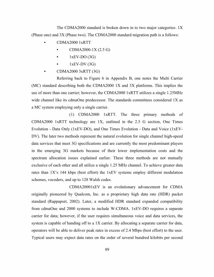
89
The CDMA2000 standard is broken down in to two major categories- 1X
(Phase one) and 3X (Phase two). The CDMA2000 standard migration path is a follows:
• CDMA2000 1xRTT
• CDMA2000-1X (2.5 G)
• 1xEV-DO (3G)
• 1xEV-DV (3G)
• CDMA2000 3xRTT (3G)
Referring back to Figure 6 in Appendix B, one notes the Multi Carrier
(MC) standard describing both the CDMA2000 1X and 3X platforms. This implies the
use of more than one carrier; however, the CDMA2000 1xRTT utilizes a single 1.25MHz
wide channel like its cdmaOne predecessor. The standards committees considered 1X as
a MC system employing only a single carrier.
(1) CDMA2000 1xRTT. The three primary methods of
CDMA2000 1xRTT technology are 1X, outlined in the 2.5 G section, One Times
Evolution - Data Only (1xEV-DO), and One Times Evolution - Data and Voice (1xEV-
DV). The later two methods represent the natural evolution for single channel high-speed
data services that meet 3G specifications and are currently the most predominant players
in the emerging 3G markets because of their lower implementation costs and the
spectrum allocation issues explained earlier. These three methods are not mutually
exclusive of each other and all utilize a single 1.25 MHz channel. To achieve greater data
rates than 1X’s 144 kbps (best effort) the 1xEV systems employ different modulation
schemes, vocoders, and up to 128 Walsh codes.
CDMA20001xEV is an evolutionary advancement for CDMA
originally pioneered by Qualcom, Inc. as a proprietary high data rate (HDR) packet
standard (Rappaport, 2002). Later, a modified HDR standard expanded compatibility
from cdmaOne and 2000 systems to include W-CDMA. 1xEV-DO requires a separate
carrier for data; however, if the user requires simultaneous voice and data services, the
system is capable of handing off to a 1X carrier. By allocating a separate carrier for data,
operators will be able to deliver peak rates in excess of 2.4 Mbps (best effort) to the user.
Typical users may expect data rates on the order of several hundred kilobits per second

90
depending on the number of users, the propagation conditions, and vehicle speed. The
expected throughput rates are still sufficient to support web browsing, email access, and
m-commerce applications (Rappaport, 2002).
Adaptive rate operations allow 1xEV systems to achieve
theoretical forward link data rates of 2.4 Mbps via a single 1.25 MHz channel. The base
station rapidly adapts it its data rate to each user by measuring the channel condition of
each MTS via pilot signals. After determining the quality of each user’s channel, the
BTSs selects a suitable multi-level modulation format, either QPSK, 8-PSK and 16-
Quadrature Amplitude Modulation (QAM) in order to deliver the highest data rate
possible for the given channel condition. Eight-phase shift keying and 16 QAM provide
three to four times more bandwidth efficiency when compared to IS-95’s Binary Phase
Shift Keying (BPSK) modulation. Additionally, 1xEV systems utilize a packet based
time division-multiplexing scheme to improve available air resources and increase
capacity on the forward link (Airvana, 2001).
The 1xEV system uses CDMA for its reverse channel and is
capable of supporting data rates from 9.6 kbps to 153.5 kbps utilizing adaptive rate
control. The BTS can control the data rate of the terminals, both individually and
globally, and thereby increase total reverse link throughput while controlling interference
(Airvanna, 2001)
By 2004 or 2005, 1xEV-DV should become available for
deployment (Carnese, 2001). 1xEV-DV will bring data and voice services for
CDMA2000 back into one carrier. A 1xEV-DV carrier will provide not only high-speed
data and voice simultaneously, but will also be capable of delivering real-time packet
services.
(2) CDMA2000 3xRTT. CDMA2000 3X MC platform employs
both wideband (reverse channel) and several narrow band channels (forward channel) in
the process of achieving the required IMT-2000 data throughput rates. This is different
from the 1X and W-CDMA platforms, which utilizes a direct spreading technique across
a single 1.25 MHz or 5 MHz channel respectively. Multiple carrier technique spreads the
data over the 1.25 MHz with a chipping rate of 1.28Mcps in a similar fashion as 1X and

91
W-CDMA; however, CDMA2000 3X positions multiple 1.25 MHz channels adjacent to
each other to creating a wider channel capable of higher data transmission rates in the
forward or downlink direction. The CDMA2000 3X standard combines three 1.25 MHz
channels to form a 3.75 MHz channel with an equivalent chip rate of 3.684 Mcps (1.28
Mcps x 3). The system places a 625 kHz guard band on each side of the MC channel to
buffer the channel from interference caused by adjacent cells. Total channel bandwidth
for CDMA2000 3X is 5 MHz facilitating interoperability with W-CDMA systems. Figure
8 illustrates the difference between direct spreading and multiple carrier spreading
techniques in addition to providing a comparison of the spectrum requirements of IS-95,
CDMA2000-1X, and CDMA2000-3X platforms.
Figure 8. IS-95 & 1X Direct Spread and 3X MC Comparison (From: Smith & Collins, 2002, p. 161)
Smith and Collins (2002) believe that IS-95, CDMA2000-1X and
CDMA2000-3X will coexist in the same market and possibly within the same cell site.
The migration path is dependent on the current system 2G system employed and the
spectrum available or owned by the operator in addition to other critical dimensioning
and cost factors that are beyond the scope of this research.
(3) Common Concepts of CDMA2000. CDMA2000 enhances the
core capabilities of IS-95/J-STD-008 networks through modulation scheme changes,

92
newer vocoders, uplink pilot channels, expansion of Walsh codes and channel bandwidth
changes. More specifically, CDMA2000 uses expanded Walsh codes (128 for phase one
and 256 for phase two), QPSK (forward link) and Hybrid Phase Shift Keying (HPSK)
(reverse link) modulation techniques, and improved vocoders to achieve the required data
rates. Both CDMA2000 phases utilize new channel types for the radio access scheme and
were required to support high-speed data in addition to some other functions such as
paging.
A total of nine forward and six reverse link channels are defined
for both CDMA20001X and 3X systems. The standard also describes two different
Spreading Rates (SR-1 and SR-3) and nine different Radio Configurations (RC-1 through
RC-9). CdmaOne and CDMA2000 1X implementations utilize SR-1, which has chip rate
of 1.228 Mcps. CDMA2000 3X system are capable of using the SR-3 technique which
produces a signal that has a chip rate of 3.6864 Mcps. However, it is important to note
that SR-3 builds on the new coding implanted in SR-1 system but supports higher data
rates.
The RCs incorporate different modulation, coding, and vocoders.
Radio configuration one and RC-2 utilize BPSK modulation whereas RC-3 through RC-9
makes use of QPSK modulation. In addition to the different modulation schemes, RC-1
through 5 in the forward channel utilizes SR-1 and supports theoretical data rates of
230.4 kbps; the appropriate reverse channel also supports the same data rate. RCs six
through nine in the forward channel utilize SR-3 and are capable of theoretical rate of
1.036 Mbps with same capability on the appropriate reverse channel. Lastly, the different
radio configurations use different channel coding rates ranging from 1/2 to 1/6 rate and
some use punctured channel coding to increase data transmission by up to fifty percent
(Harte, Levine & Kikta, 2002). Tables 9 and 10 summarize the forward and reverse
channel radio configurations.
Radio Configuration
Spreading Modulation
Spreading Rate
Chip Rate (Mcps)
Channel Coding
Data Rate (kbps)
1 BPSK SR-1 1.228 1/2 1.2 – 9.6 2 BPSK SR-1 1.228 1/2
punctured 1.8 – 14.4
3 QPSK SR-1 1.228 1/4 1.5 – 153.6
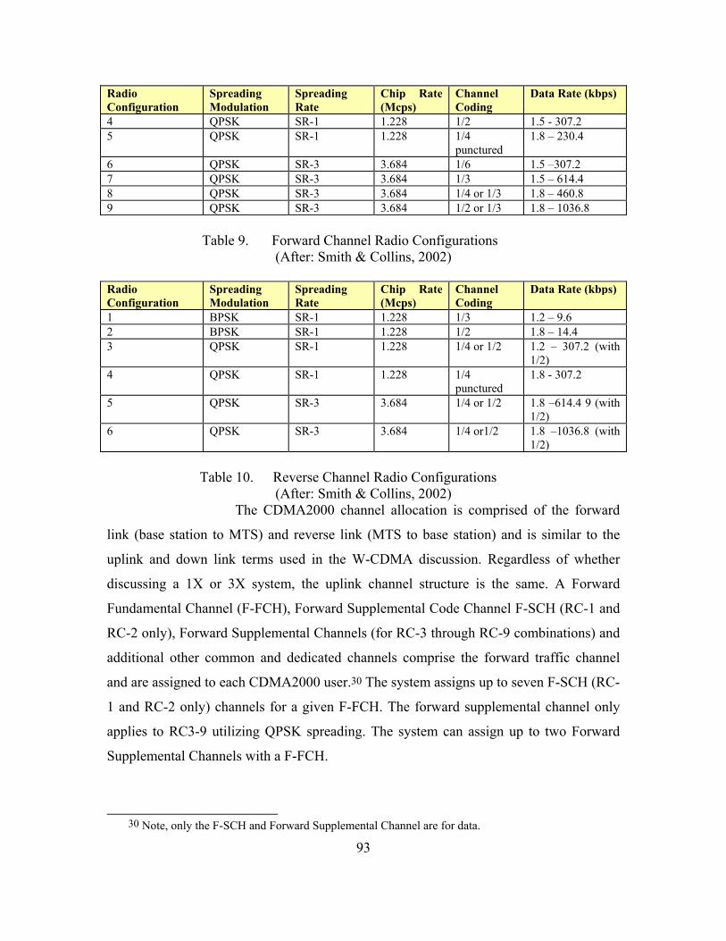
93
Radio Configuration
Spreading Modulation
Spreading Rate
Chip Rate (Mcps)
Channel Coding
Data Rate (kbps)
4 QPSK SR-1 1.228 1/2 1.5 - 307.2 5 QPSK SR-1 1.228 1/4
punctured 1.8 – 230.4
6 QPSK SR-3 3.684 1/6 1.5 –307.2 7 QPSK SR-3 3.684 1/3 1.5 – 614.4 8 QPSK SR-3 3.684 1/4 or 1/3 1.8 – 460.8 9 QPSK SR-3 3.684 1/2 or 1/3 1.8 – 1036.8
Table 9. Forward Channel Radio Configurations
(After: Smith & Collins, 2002)
Radio Configuration
Spreading Modulation
Spreading Rate
Chip Rate (Mcps)
Channel Coding
Data Rate (kbps)
1 BPSK SR-1 1.228 1/3 1.2 – 9.6 2 BPSK SR-1 1.228 1/2 1.8 – 14.4 3 QPSK SR-1 1.228 1/4 or 1/2 1.2 – 307.2 (with
1/2) 4 QPSK SR-1 1.228 1/4
punctured 1.8 - 307.2
5 QPSK SR-3 3.684 1/4 or 1/2 1.8 –614.4 9 (with 1/2)
6 QPSK SR-3 3.684 1/4 or1/2 1.8 –1036.8 (with 1/2)
Table 10. Reverse Channel Radio Configurations
(After: Smith & Collins, 2002) The CDMA2000 channel allocation is comprised of the forward
link (base station to MTS) and reverse link (MTS to base station) and is similar to the
uplink and down link terms used in the W-CDMA discussion. Regardless of whether
discussing a 1X or 3X system, the uplink channel structure is the same. A Forward
Fundamental Channel (F-FCH), Forward Supplemental Code Channel F-SCH (RC-1 and
RC-2 only), Forward Supplemental Channels (for RC-3 through RC-9 combinations) and
additional other common and dedicated channels comprise the forward traffic channel
and are assigned to each CDMA2000 user.30 The system assigns up to seven F-SCH (RC-
1 and RC-2 only) channels for a given F-FCH. The forward supplemental channel only
applies to RC3-9 utilizing QPSK spreading. The system can assign up to two Forward
Supplemental Channels with a F-FCH.
30 Note, only the F-SCH and Forward Supplemental Channel are for data.

94
CDMA2000 reverse link structure is similar to that of the forward
link; however, it is important to note it that the reverse channel for 3X is a direct spread
over the 3.75 MHz and is not a multi-carrier distributed. Despite this difference, Smith
and Collins (2002) indicate that it 3X structure can be overlaid a 1X implementation.
Similar to the forward link, the reverse link consists of a Reverse Fundamental Channel
(R-FCH) for voice and Reverse Supplemental Code (R-SCH) and Reverse Supplemental
Channels for data. The system assigns up to seven R-SCH (RC-1 and RC-2 only)
channels with a given R-FCH. Like the forward channel, the system can assign up to two
Reverse Supplemental Channels with a fundamental channel.
As previously mentioned, CDMA2000 increases the number of
Walsh codes from 64 codes to 128 and 256 for CDMA2000 1X and 3X networks
respectively. The introduction of QPSK channel spreading enabled the increase to 128
Walsh codes. CDMA2000 3X doubles the number of Walsh codes from 128 to 256 by
using quasi-orthogonal masking functions (Hart, Levine & Kikta, 2002). Additionally,
CDMA2000 ushers in the use of variable length Walsh codes, ranging from 2 to 256, to
accommodate fast packet rates and allow for variable bandwidth (Hart, Levine & Kikta,
2002). Smith and Collins (2002) point out that the variable length Walsh code can impact
the number of user’s in a given cell because orthogonally must be maintained. To
explain, higher data rates require shorter Walsh codes in order to maintain the same
spreading rates. The shorter Walsh code equates to fewer codes available to share across
the channel, thus fewer simultaneous users. This limitation implies that the type of data
transmitted over the network, such as video, can directly impact the number of user that
can access a particular cell and requires network engineers to design a CDMA2000
network based on expected voice and data traffic. This limitation is similar to that
explained in the W-CDMA channelization code discussion. However, engineers can
employ a dedicated a single channel for packet data only in areas where heavy data
services are forecasted thus preserving voice platform availability and required data
throughput (Smith & Collins, 2002).
b. System Architecture
Whether discussing a CDMA 1X or 3X system, both require relatively
minor upgrades to the existing cdmaOne radio and core network. It is possible to migrate

95
cdmaOne systems all the way to 3X capability with no additional RF equipment and only
software and baseband hardware changes (Rappaport, 2002). When compared to the
migration path for W-CDMA, many advocates of CDMA2000 claim the standard
provides operators with a more seamless and less expensive upgrade path since
CDMA2000 allows the same spectrum, bandwidth, RF equipment, and air interface
framework to be used at each base station as the 3G upgrades are introduced over time.
Figure 9 shows a simple block diagram of a CDMA2000 implementation
identifying the upgraded and new components required to support IP packet services.
Module additions or swaps comprise the upgrades to existing cdmaOne BTSs and BSCs.
Components that are new to the system make up the packet switched data segment of the
CDMA2000 network. These new components include a Packet Data Serving Node
(PDSN), Authentication, Authorization and Accounting (AAA), Home Agent (HA),
Routers, and a Firewall.
Figure 9. CDMA2000 System Architecture
(From: Smith & Collins, 2002, p. 288)
The MTS, Radio Network (RN), and the core network make up the
CDMA2000 network architecture. Figure 9 shows how each component of the network
interacts to connect the user to fixed public telephone, Internet, and private networks. The

96
CDMA2000 network segregates the circuit switched portion from the packet switched as
the traffic leaves the RN usually at the BSCs in a similar fashion as W-CDMA.
The PDSN is at the core of the CDMA2000 packet switched network and
is supported by Smith and Collins (2002) when they state, “the PDSN is the heart of the
packet data services for a CDMA2000 network” (p. 288). The PDSN is responsible for
supporting packet data services and performs seven major functions in the course of a
packet data session. The seven major functions are as follows:
• Initiates, maintains, and terminates Point to Point Protocol (PPP) sessions with the MTS
• Supports both Simple and Mobile IP packet services
• Establishes and maintains the logical links to the radio network across the radio packet interface
• Initiates AAA for the mobile station client to the AAA server
• Receives service parameters for the mobile client from the AAA server
• Routes packets to and from external public and private data networks
• Collects usage data that is relayed to the AAA server
Another new component to the system is the AAA server. It is clear by its
name that AAA is responsible for authenticating, authorization, and accounting functions
for the packet data network portion of the CDMA2000 network. The AAA communicates
with the PDSN via IP and performs the authentication associated with PPP and mobile IP
connections. Additionally, the AAA checks the subscriber’s service profile and is
responsible for security key distribution and management in its authorization capacity
and of course keeps track of accounting with respect to data services for billing purposes.
A HA joins the network and is normally compliant with the Wireless IP
Network Standard (IS-835). The HA performs a myriad of tasks and is specifically
responsible for tracking the location of the mobile IP user as it moves through the
CDMA2000 network. This function ensures the proper delivery of the packets to the
MTS as it migrates through the network.
The routers that are involved in the CDMA2000 network are responsible
for routing IP traffic to and from various core network elements within the CDMA2000.

97
They are also responsible for routing traffic to and from the internal network to both
external public and private IP networks. The firewall is required to ensure security when
accessing external data applications.
Additional subscriber information associated with the introduction of
packet data services, which includes subscriber packet data service options, MTS
capabilities, and voice platform needs are stored in the upgraded Home Location Register
(HLR). The Visitor Location Register (VLR) pulls this data to the associated network as
a result of a successful subscriber registration process.
The radio network upgrades include additional element cards to the BTS.
The BTS controls the air interface between the CDMA2000 network and the MTS. The
BTS is responsible for allocating radio resources (multiple carriers), forward power
required for traffic overhead and soft handoffs, and Walsh code assignment. The BTS
decides how best to distribute its resources based on the service requested, the RC, the
subscriber type, and whether the service requested is voice or packet.
The BSC is responsible for controlling all the BTSs under it purview.
Referring back to Figure 9, one sees the BSC routes packets to and from the BTSs and
the PDSN. Also, it is responsible for routing time domain modulated traffic to the circuit
switched network.
c. Packet Data Transfer Data traffic can flow either over the circuit or the packet switched
network. If the data travels of the circuit switched it is handled the same as voice traffic.
But as mentioned above, all packet data calls must go via the PDSN that essentially
serves as the interface between the air interface data transport and the fixed network
transport. There are three packet data service states: active/connected, dormant, and
null/inactive. When packet data is bi-directionally flowing between the MTS and BTS
over a physical channel an active/connected condition exists. In a dormant state, no
physical traffic channel exists but there is a PPP link between the MTS and the PDSN.
For a null/inactive state neither a traffic channel nor PPP is maintain or established.

98
The MTS initiates voice, packet, or concurrent voice and data sessions.
The PDSN does not communicate to the HLR or VLR to obtain the necessary subscriber
information; instead, it communicates with AAA server. If the session involves data, the
PDSN is designed to provide several key packet data services including Simple IP and
Mobil IP and is capable of establishing Virtual Private Network (VPN) services with
either Simple or Mobile IP.
Simple IP is where the subscriber is assigned static IP address using
Dynamic Host Configuration Protocol (DHCP) services from the serving PDSN with its
routing service provided by the local network. The MTS in an active or dormant state is
free to roam from cell to cell within a network providing it does not enter a cell served by
a different PDSN. Moving into a cell serviced by a different PDSN will result in the
termination of the data session. When this happens the subscriber negotiates for another
IP address from the new PDSN and must reinitiate the session. Simple IP is an
origination-based service because it fails to provide for mobile termination (Smith &
Collins 2002). More specifically, Simple IP is a PPP service using DHCP.
In Mobile IP, the public IP network provides the MTS IP routing service.
The MTS is assigned a static IP by the PDSN and is stored in the HA. The establishment
of the static IP address facilitates roaming during packet sessions, assuming the IP
address scheme is unique enough for the MTS to be distinctively identified (Smith &
Collins, 2002). Mobile IP overcomes the Simple IP roaming limitation via the HA and
the assignment of a Care of Addresses (COA).
As the MTS enters a new cell served by a different PDSN, that PDSN acts
as the Foreign Agent (FA) and the home agent, located in the home network, is setup as a
virtual HA. The MTS registers each time it begins a packet data session, regardless of
whether it originating or terminating the session. An IP-in-IP tunnel is established
between the HA and the FA and is used to deliver IP traffic to the visiting network PDSN
(FA).
When roaming, the MTS is responsible for informing the CDMA2000
network it has moved to another service. Once this has occurred, the MTS registers with

99
another FA, who then assigns the MTS a Care of Address (COA) which is sent to the
HA. However, the MTS still retains the original static IP address. The home agent
forwards the packets to the visited network via an IP-in-IP tunnel for delivery to the MTS
by encapsulating the original IP packet with the COA. The packet arrives at the FA where
it removes the COA wrapper and forwards the original packet, with the original static IP
address, to the MTS. The MTS retains its static IP address the entire time, thus
facilitating TCP’s ability to maintain a proper connection.
In the reverse direction, the routing of IP packet occurs the same as if the
MTS is on the home network and does not require an IP-in-IP tunnel. However, Dornan
(2002) explains this Mobile IP process leads to problems when sending data to another
network. He points out that every packet includes the sender’s IP address, which for the
mobile user may not match the network they are actually in. Many firewalls see this
inconsistency as a spoofing attempt from a hacker and results in the packet being
rejected.
Two other variants of Simple IP and Mobile IP supported by the PDSN
include using of VPN technology. This enhancement allows for higher security and also
provides connectivity to corporate local area networks and intranets. The system is able
to provide this service using VPN tunneling protocols between the private network and
the PDSN. Since VPN’s essentially connect the mobile client to the companies LAN as if
it were a part of it, the private network is responsible for assigning the MTS’s IP address.
B. SUMMARY Reviewing Appendices A, B, and C, one can more clearly see how and why the
cellular operator’s pursuit of IMT-2000 and 3G services can take various paths. Factors
such as existing 2G infrastructure, available spectrum, and market expectations all play a
major role in the cellular operator’s decisions to implement a particular 2.5G and
subsequent 3G platforms. As of January 2003, only four countries, Japan, South Korea,
Austria and the United States have deployed true 3G platforms (3G is Here Today – 3G
Operators, 2003). Japan’s DoCoMo debuted their Freedom of Mobile Access (FOMA)
W-CDMA 3G network in spring 2001 and rolled out services to the general public in the
100
Tokyo area that autumn. This action made Japan the first country to introduce 3G
services. On 4 December 2001, Manx Telecom switched on Europe’s first 3G W-CDMA
systems on the Isle of Man located between Great Britain and Ireland. Two operators in
South Korea successfully launched CDMA2000 1xEV-DO 3G services in the first half of
2002.
Based on the Asian market, industry experts feel CDMA2000 1X operators are
currently in the best position thanks to lower cost for network upgrades, better capacity
and speed, and affordable and attractive handsets (Carvalho & Shuper, 2002). In their
report Carvalho and Shuper (2002), estimate that Sprint PCS would incur a $1.6 billion
dollar cost to reach CDMA1xEV-DO while AT&T Wireless would have to spend nearly
three times that amount to upgrade to W-CDMA. It appears that both the higher cost for
W-CDMA network upgrades and delays in handset availability is hindering W-CDMA
deployment. Despite these short-term problems, experts believe in the long run the cost
advantages of W-CDMA can be significant as they expect seventy-five percent of
subscribers globally to ultimately migrate from GSM to W-CDMA (Carvalho & Shuper,
2002). The same experts believe W-CDMA phones will need extra RF chipsets to work
with the new W-CDMA frequency in Europe and require more transistors to support
backward compatibility with GSM. It is because of the added costs of these additional
chipsets that one questions whether the aforementioned W-CDMA scale advantage will
materialize. The same is not true for CDMA2000 phones.
As of this writing, Western Europe is mostly deploying GSM/GPRS 2.5G
platforms while U.S. operators are rolling out a mix of GSM/GPRS and CDMA-1X 2.5 G
services. It is likely that, since GSM operators possess sixty percent of the market share
as compared to IS-95’s twelve percent, W-CDMA will be the most predominant 3G
platform deployed despite its slower and more costly introduction (Harte, Levine &
Kikta, 2002). But to the global roamer it is important to remember that the IMT-2000
envisions global roaming between these two most predominant systems through the use
of multimode smart phones and MTSs capable of W-CDMA and CDMA2000 operations.

101
LIST OF REFERENCES
3G is Here Today – 3G Operators (2003). 3G Today. Retrieved January 26, 2003 from http://www.3gtoday.com/operators_flash.html
Ahmed, I. (2002). “Enabling Web Applications for Wireless Devices”. Sun.com. Retrieved October 30, 2002 from http://wwws.sun.com/software/xml/developers/iftwireless
Carnese, W. (2001). CDMA 2000. Retrieved August 18, 2002 from http://www.ericson.com/cdmasystems/3gcdma2000shtml.
Carvalho L. and Shupper, M. (2002). Wireless Technology: Who is Ahead? Morgan Stanley Co. Retrieved September 10, 2002 from http://www.cdg.org/3gpavilion/resources/morgan_stanley_june02.pdf
Department of Commerce (2002, July 23). Bush Administration Forges Landmark Plan for Spectrum Allocation: Spectrum Made Available for Advance Wireless Services. Retrieved September 12, 2002 from http://www.ntia.doc.gov/ntiahome/press/2002/va7232002.htm
Dornan, Andy (2001). The Essential Guide to Wireless Communications Applications; From Cellular Systems to WAP and M-Commerce. New Jersey: Prentice Hall PTR.
Evans, Nicholas (2002). Business Agility: Strategies for Gaining Competitive Advantage through Mobile Business Solutions. New Jersey: Prentice Hall PTR.
Flynn, Jim, (2002). Mobile Enterprise Architecture-The Choices. Retrieved on November 4, 2002 from http://www.associatedsoftwaredevelopers.com/Mobile%20Enterprise%20Architecture.doc
Harte, L., Levine, R., and Kikta, R. (2002). 3G Wireless Demystified. New York: McGraw-Hill.
Held, Gil (2001). Data Over Wireless Networks; Bluetooth,WAP & Wireless LANs. New York: McGraw-Hill.
Kalakota, R. and Robinson, M. (2002). M-Business: The Race to Mobility. New York: McGraw-Hill
Lykins, Don (2002). “The Insurance Industry Goes Mobile”. Mobile Business Advisor.com. Retrieved on October 18, 2002 from http://itarchitectadvisor.com/doc/11170

102
MobileQ (2002). Debunking Mobile Application Myths; The Real Issue is User Experience. Retrieved on November 12, 2002 from http://img.cmpnet.com/mbizcentral/whitepapers/MobileQ-DebunkingtheMobilityMyths.pdf
Neisley, Ed (2002, July). “Chemical Attraction”. Dr Dobbs Journal. Retrieved October 15, 2002 from http://www.ddjembedded.com/resources/articles/2002/0207m/0207m.htm
Rappaport, T. (Ed.) (2002). Wireless Communications: Principals and Practice. (2nd ed.) New Jersey: Prentice Hall.
Smith, Clint and Collins, Daniel (2002). 3G Wireless Networks. New York: Mc Graw-Hill.
SPAWAR Systems Command (2002). Optimized NALCOMIS OMA User Guide. Space and Naval Warfare Center, Norfolk, Virginia, 2002.
Task Force Web (2001). Web Enabled Navy Architecture Version 2.0. Retrieved September 21, 2002 from https://ucso2.hq.navy.mil/n09w/webbas01.nsf/(vwwebpage)/webbase.htm?OpenDocument
The Shosteck Group (2001). GSM or CDMA: The Commercial and Technology Challenges for TDMA Operators. California: CDMA Development Group.
Tomasi, W. (Ed.) (2001). Electronic Communications Systems: Fundamentals through Advanced. (4th ed.) New Jersey: Prentice Hall.
U.S. Navy Department (2001). NATOPS General Flight and Operating Instructions. OPNAVINST 3710.7S. Retrieved December 13, 2002 from http://www.hq.navy.mil/natops/html/products_3.htm
U.S. Navy Department (2001). The Naval Aviation Maintenance Program (NAMP). OPNAVINST 4790.2H. Retrieved December 12, 2002 from https://www.nalda.navy.mil/nalda/secured/4790/

103
INITIAL DISTRIBUTION LIST
1. Defense Technical Information Center Ft. Belvoir, Virginia 2. Dudley Knox Library
Naval Postgraduate School Monterey, California
3. Technical Coordinator Aviation Systems Directorate
Space and Naval Warfare Systems Center Norfolk, Virginia