,0:$3urfhhglqjv … · what involved crushing, development oi' cracks and fissures as well as...
TRANSCRIPT

MINE WATER. GRANADA. SPAIN.1985
THE WATER PROBLEM IN RELATION TO MINING AT MAGNESITE DEPOSITS IN SLOVAKIA
Dusan Cabala Geologicky prieskum, n.p. Spisska Nova Ves, Markusovska cesta,
Czechoslovakia
ABSTRACT
The present paper lays special emphasis on the results .of' the the surveys and measures being taken for the exploitation of' Slovak magnesite deposits. It shortly reviews the present practice of' mine water control on magnesjte deposits under strong karstic water hazard characterizf'd by relatively large amounts of' water inrushes which may cause partial or total inundation, temporary break-down and endangerment of' human life. Some characteristics and defined cases of actively expJoited deposits are reported, too.
INTRODUCTION
The Slovak magnesite deposits in the Slovak Ore Mts. (Slovenske rudohorie) are situated in a belt reaching by its western part in to the Lucenec Basin and in the eastern one in to the Kosice Basin. The deposits participate in two main West Carpathian tectonic units called Veporic and Gemeric one (see Fig. 1- Distribution of Crystaline Magnesite Deposits). In the Veporic there are some talk-bearing magnesite deposits with in the Kokava and Hnust'a regions located in mesozonal crystalline schists of Pre-Carboniferous age while the Gemeric unit bears .a li thos tra tigraphi c horizon of originally biohermal carbonates embedded in epizonally metamorphosed Upper Carboniferous series and partially altered by metasomatic processes into magnesite. Carbonate bodies occur in a more or less continuons belt of 70 km length from Podrecany to Gchtina. After a gap in the central part of the unit, the same belt appears again only in the Kosice area. This belt contains all West Carpathian magnesite deposits of high economic importance being under exploatation at the present time.
GEOLOGY AND STHUCTl:JRE
The lithostratigraphic scheme of the Upper Carboniferous sequence in some magnesite deposits is for better orientation shown in Fig. 2. Upper Carboniferous and layers of the Devonian Rakovec Group occur between two thrust lines separating them from the Vepo-
919
IMWA Proceedings 1985 | © International Mine Water Association 2012 | www.IMWA.info
Reproduced from best available copy

ric (Lubenik-Margecany Line on the north) and £rom the Lower Paleozoic Gelnica Group or Gemeride Mesozoic (Hradok-Zeleznik Line one) on the south.
FIG.1. DISTRIBUTION OF CRYSTALLINE MAGNESITE DEPOSITS (ADAPTED BY ABONYI, 1981)
49•
'IZ:J 2E;3l
30 "§ Sb,d 6f±3
1-Neogene, 2-Paleogene, 3-sediments o£ the border synclinal structure between the Gemeric and Veporic (Devonian to Upper Carboni£erous), 4-Mezozoic o£ the Gemeric unit, 5-Paleozoic of the Gemeric unit, 6-Veporic unit, 7-nappe overthrust plane, 8-fault, 9-deposit of magnesite
Mg-metasomatism led to the development of economically important magnesite accumulations namely between these linea. Repeated nappe movements along the tectonic plahes of Lower Cretaceous up to Paleogene age resulted in partial thrusts and in further complications of the internal geological structure. The last movements occurred along normal faults. The already existing tectonic planes have been prevailingly reactivated and modified by these movements. In such a way, new system of tectonic planes generated pronouncedly segmenting the deposits proper and the wall rock, too. The development o£ main, frequently widely open, tectonic lines with karst phenomena is referred to this period, too. The Upper Carboniferous rocks are immediately underlai'n mostly by the Rakovec Group and beneath this group, and the Lubenik-Margecany Line, Permian or Mesozoic cover sequences of the Veporic are present. In the overlier, there are chiefly tectonically thrust struc-tures of the Gelnica Group or eventually o£ Gemeric Mesozoic rocks.
920
IMWA Proceedings 1985 | © International Mine Water Association 2012 | www.IMWA.info
Reproduced from best available copy
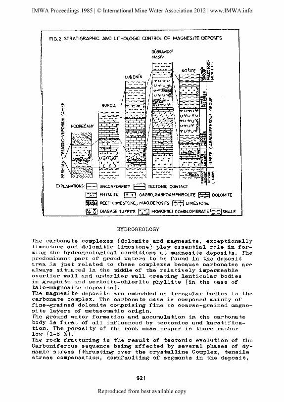
FIG.2. STRATIGRAPHIC AND LITHOLOGIC CONTROL OF MAGNESITE DEPOSITS
oUBRAVSKY MAslv
EXPLANATIONS:E:::J UNCONFORMITY O TECTONIC CONTACT
!-;...-! PHYLLITE ~ GABRO,GABROAMPHIBOUTE ~DOLOMITE
~REEF LIMESTONE, MAG.DEPOSITS ~LIMESTONE
llll DIABASE TUFFITE , ••• ·' MONOMICT CONGLOMERATE E=-=1SHALE
HYDROGEOLOGY
The carbonate complexes (dolomite and magnesite, exceptionally limestone and dolomitic limestone) play essential role in forming the hydrogeological conditions at magnesite deposits. The predominant part of groud waters to be found in the deposit urea is just related to these complexes because carbonates are always situated in the middle of the relatively impermeable overlier wall and underlier wall creating lenticular bodies in graphite and sericite-chlorite phyllite (in the case of talc-magnesite deposits). The magnesite deposits are embedded as irregular bodies in the carbonate complex. The carbonate mass is composed mainly of fine-grained dolomite comprising fine to coarse-grained magnesite layers of metasomatic origin. The ground water formation and accumulation in the carbonate body is first of all influenced by tectonics and karstification. The ~orosity of the rock mass proper is there rather low (1-8 %J. The rock fracturing is the result of' tectonic evolution of the Carboniferous sequence being affected by several phases of' dynamic stress (thrusting over the crystalline Complex, tensile stress compensation, dowr~aulting of segments in the deposit,
921
IMWA Proceedings 1985 | © International Mine Water Association 2012 | www.IMWA.info
Reproduced from best available copy

what involved crushing, development oi' cracks and fissures as well as strong karstification along the discontinuity planes. The carbonate rock matrix itself is tight and the basis elements in rock hydraulics are attributed to discontinuities in the rock mass. Discontinuities increase tho water-bearing capacity. The rock mass is heterogeneous regarding its waterbearing capacity and the condition for water transmision varies considerably depending on the degree of tectonic fracturing. Correspondence exists between the hydraulic conductivity and prevailing stress distribution in the rook mass. The hydraulic conductivity values of the rocks penetrated by wells were calculated 1,5-lo-7- 6.lo-5 m/s, but values calculated for fractured zones are several times higher than of the rock mass. The hydraulic conductivity usually decreases with increasing depth chiefly caused by the decrease of fracture frequency and thickness, but tectonic zones at greater depths are of critical importance for the water-bearing capacity of the rock. Water has been an ever-present problem for mining operations and may cause disposal problems. There are several hydrogeological settings in which water may be problem in mine. The most common hydrogeological setting in which large volumes of wator may occur in mine is the situation where workings approach the tectonic zones with well developed karst phenomena and those are relatively widely distributed in the deposits. Inflows of different form and nature are there distinguishable. Concentrated inflows occur in the open faults, caverns and karst cavities. Those coming from karstic phenomena have frequently the nature of inrush (in average 3,500 m3 of water and even more) resulting in flooding the mines by water and gouge (rock material which has been ground to a uniformly fine particle size of clay and sand). Due to the inrushes mentioned, mining must be stopped frequently and sometimes it may result in a serious damage of vertical and horizontal workings (shafts, drifts). Recharge of water occurs where precipitation infilt~ates to the mine and is concentrated in the areas where surface depresions, open pits, subsidence areas and crop faults are connected directly with underground. mine workings. Surface water can be also lost from the stream that traverses the broken ground. Water is removed. from individual mines either by pumping to the surface or providing tunnels for gravity drainage. Drainage influences the natural ground water conditions partly as a change in recharge and partly due to piezometric head. lowering, somewhere causes decrease in spring outflow from the carbonate complex and phyllites as well. The direction of natural ground water flow is generally towards the deeper-seated parts of deposits exploited. Generally, it has been estimated that less than 30 % of pumpage Volume proceeds from direct rain infiltration, and 50-60 % seems to flow from deeper aquifers and specific fractured zones. Another small fraction might correspond to inflows from near-by streams which are in hydraulic connection with the aquifer. Hydrogeological factors affecting the flow and quality of mine drainage are shown in Table 1.
922
IMWA Proceedings 1985 | © International Mine Water Association 2012 | www.IMWA.info
Reproduced from best available copy

Table 1. Basic hydrogooloc;ical facto~"S that may effect mine" drainage
Factors
Thickness of carbon. complex m
Mat~nes
Podrecany B-urda
Karstic w.hazard
Inflows m3/day
Inrush max. m3
Degradation stream water quality by m.drainage
Surficial stream influence
Incr. infil t. due to land subsidence, open pits
100-150
+
1,440-17,280
4,000
+
+
+
240
+
1,290-15' 81~0
5' 500
+
+
i t d e p o s i t Lubenik Dubr.masiv
130
+
290-2,160
850
+
+
+
4so
+
1 41~0-4:320
2, 500
+
+
Kosice
170
+
2,592-7,200
10,000
+
+
The present practice of karst water control is being made by dewatering and preventive control using cover holes or utilizing protective layers. Bearing in mind the relatively frequent occurrence of karst phenomena with water (gouge) reservoirs in the front of driven workings, (in some deposits) cover holes are drilled into headings with special design and length of 100 to 150 m oriented from the cubies 2-4 degrees outwards. At strategic points, water doors are placed in order to protect some critical installations as pump stations a.o. Inrush water could be stored temporarily in worked-out areas and fed to the pumps at convenient rates.
The ground water .chemistry in magnesite deposits closely correlates with mineralogical-petrographic nature of the rock mass where these waters are being formed. From genetic point of view, there are ground waters of atmospherogenic type and of petrogenic subtype. In the carbonate rocks, carbonatogenic waters occur mainly while silicatogenic waters are present in the hanging walls and foot walls (phyllites, shales). Except for mineralogical nature of the rock mass, the ground water chemistry is influenced by numerous agents. From secondary influences, it is mainly the air pollution in the neighbourhood of magnesite deposits what results in increased salinity of precipitations infiltrating into the rock mass and the deposits in question as well. In the proximity of some magnesite deposits, up to 2150 t/km2 of fly ashes a year (80 % consisting of Mg·O) have been noticed.
923
IMWA Proceedings 1985 | © International Mine Water Association 2012 | www.IMWA.info
Reproduced from best available copy

The summary classif'ica tion diagram of' ground water chemill! tr".{ applied to all magnesite deposits discussed is in fig. 3.
FIG.3 SUMMARY CLASSIFICATION [')IAGRAM OF GROUNOV'.ATER CHEMISTRY
.. I
~0 NaCt
MINERALISATION (mg It )
~ ~ § § ~ ~ . ' . . .. , ...
MAG. DEPOSIT : • PODRE~ANY • BURDA c DUBRAVSKY MASN
• LUBEN{K • KO~ICE + SPRING TEPLA VODA
Carbonate dissolution is considered as the main process in the deposit water formation while suphide oxidation takes there also place but in les.'5er amounts (pyrite is usually present as minute grains dissePlinated in dolomite and dolomitic shale).
Some characteristics and peculiar si-t:uations on five magnesite deposits are reported below.
THE PODRECA1\Y DEPOSIT
The Podrecany Deposit is known to have been mined for ochres (an earthy variety of gossan) already since the beginning of' the eighteenth century. Upper Carboniferous beds occur there in a narrow tectonic syncline amidst rocks referred to the Gemeric and Veporio units and covered by Cenozoic sediments. Several magne.'.!i te bodies are there cropping out to the surf'ace, wher8as in their hanging wall and foot wall graphite phyllites are present. fhe surficial situation and geological profile are shown in figs. Lf and 5. Down to a depth of 80 m, carbonates are strongly weathered and karstified. Due to tectonic disturbance and water circulation the karst phenomenon created a system filled wjth water and gouge throughout the deposit. In spite of longlasting exploitation, static waters of the deposit are not yet fully drained off from this karst. In those pa.rt:'l of th'3 deposit whe.r•) kar·s t wa te.rs are presumed, g"'ophys.i.cal measurements awl cover holes are realized to pro teet the workings. lllfe \•ater-bea.ring karst is of' diff'erent size the greatest wa''-'1' and gouge volumes of inrush nature observed have up to ; , (i\lO m3.
924
IMWA Proceedings 1985 | © International Mine Water Association 2012 | www.IMWA.info
Reproduced from best available copy

Grounrl waters are drained by pumping to the surface from the lowPrmos t level of workings. Dynamic inflows of ground ,_-a ter are also due to water drain8d from the surrounding aquifers (minimum inflows l,lrlfO to 1,870 m'3/ctay) or by short-J_asting inf'lows due to increased pr8cipitation infiltration. Such increased precipitation is apparent in the underground within 5 to 6 hours. After a rainfall of storm nature ( 76 mm), maxi~um inflow exceeding 17,280 m /day has been observed. In such case the gouge is intensively washed out and for this reason the clayey sediment nrust be eliminated prior the subject water outlet into surface streams.
FIGS GEOLOGICAL SECTION OF THE PODRECANY DEPOSIT
mA.S.l
- CUIONATES- DOLOMITE, MAGNESITE ~--4 PHYLLITE
CARBONATE OI"ENIHGS-KARST PHENOMENA
THE BURDA DEPOSIT
JULIUS SHAFT
The carbonate body consists chiefly of' dolomite with thick magnesite layers embedded and has been affected by transversal faults along which weathering and large-scale karstic phenomena formation may be observed. The predominant part of' proved magnesite reserves is directly situated below the Blh surface stream. Schematic geological situation and geological section through the Burda Deposit is in fig. 6 and 7. As evidenced several times, karst phenomena (caverns and tectonic-controlled cavities) are mutually intercennected forming in such a way continuous hazard to driving openings. In the case of' a crosscut development at the 250 m level, inrush coming from
925
IMWA Proceedings 1985 | © International Mine Water Association 2012 | www.IMWA.info
Reproduced from best available copy

FIG.6. SCI-£MATIC GEOLOGICAL SITUATION OF THE BURDA DEPOSIT
0 100 200 300 lo00111
the foot wall took there place resulting in the flooding of all workings up to the a level of 300 m. After a short time, inflows disappeared from the higher levels and due to water discharge from the karst phenomena even the shaft deformed there so that mining operations had to be stopped for a longer time. In solving hydrogeological problems concerning the source of inrush waters in storage and the proposals for preventing them, etc., evaluation of the flooded area pumping tests and ground water chemistry analyses in addition to other hydrogeological works were performed and very useful, too. Surface stream infiltrations and stream regulations have to realized during mining operations performed several times. After inrushes, 10,080- 15,840 m3/day inflows have been into the deposit obser
ved the minimum one of them being 1,290 m3/day. Because of intricate hydrogeological conditions, mining operations in grea:ter depths will be not realized.
THE LUBENfK DEPOSIT
There are two shaft-open deposits (the Studena and the Amag cnes) exploited. Carbonates represented by dolomite and magnesite form there very steeply dipping lenticular layers embedded in sericite and graphite phyllite. Their strike-length (approximately E-W) is several kilometres. For surface situation and geological section through the Lubenik Deposit see fig. 8, 9 and 10. The carbonate bodies are segmented by longitudinal and cross ~etonics into several parts. Permeability depends on the density and opening of tectonic surfaces deformations affected by karstification to a considerable extent.
926
IMWA Proceedings 1985 | © International Mine Water Association 2012 | www.IMWA.info
Reproduced from best available copy

FIG.S~ SURFACE SITUATION OF LUBENlK AND oUBRAVSKY MASlV DEPOSITS
FIG.10. GEOLOGICAL SECTION OF THE DEPOSIT
100
0
Karstification is mostly developed at crossings of tectonic dislocations. Karst cavities with water and gouge filling have ellipsoid-shaped outlines running in vertical directions and reaching volumes of 100 m3 and even more.
Dynamic ground water inflows are about 290 m3/day but in case of increased precipitation they are several times higher (up to 2,160 m3/day). The rainfall influence is apparent in the underground within 16
to 22 hours.
FIG.9. GEOLOGICAL SECTION OF THE AMAG DEPOSIT
After each riew level development, increased ground water inflows must be generally expected. m A.S.L. 1
373
323
173
153
103
153
103
927
Following the drainage of static water in storage, however, there is a stabilization of the inflows mentioned. Ground waters are drained off from the workings by pumping, they must be treated, however, prior to the outlet into the sur-face streams.
IMWA Proceedings 1985 | © International Mine Water Association 2012 | www.IMWA.info
Reproduced from best available copy

TIIE DUBRAVSKY MASfV DEPOSIT
This huge carbonate body is divided, by a system of cross faults, into three parts - the Dubrava, the Mikova and the Jecll'ovec Deposits. Within this coplex, magnesite is present in form of irregular bodies. Due to good permeability and relatively high precipitation, there is a high but not continuous water-bearing capacity' associating with fault lines. The surface situation and geological section o:f the Dubravsky masiv Deposit is shown in fig. 8 and 11.
GEOLOGICAL SECTION OF THE DUBRAVSKY 1-'IASIV DEPOSIT
The ground water formation and accumulation is first o:f all related tp fissuring and karstification. Magnesites have most intensively undergone karstification and karst phenomena developed there in to a higher stage (merokarst). In rare cases, some horizontal karst phenomena (and extensive gallery and cavern system being up to 500 m long) are here present, too. At the present time, this magnesite deposits 1s mined and drained in a depth of 320m a.s.l. by a drainage tunnel (inflows are varying between 1,440 and 4,320 m3/day) and by the Tepla Voda natural spring (inflows are considered to be 1,720 m3jday) as well. Further exploitation in depth of 200m a.s.l. is now under development. Since in greater depths active karst occurrs of high waterbearing capacity and the possibility to encounter the important Tepla Voda karst spring may be expected, there is continuous inrush hazard when performing development of workings. For this reason, the control of water during development by cover holes is realized. At the present time, hydrogeological prospection is realized for :finding a subsidiary water source in case of possible encountering and pollution the Tepla Voda karst spring. On the basis of observations performed, a negative influence of exploitation on the quality of this spring (an increased contamination) has been already noticed.
THE KOSICE DEPOSIT
The lithostratigraphic sequence of the Kosice Deposit is relatively simple. There is an intricate tectonic pattern,
928
IMWA Proceedings 1985 | © International Mine Water Association 2012 | www.IMWA.info
Reproduced from best available copy

however, considered as the most important and decisive agent determining the useful component and associated rock distribuf;ion. At the same time it requires but saf'ety mining operations and good knowledge of hydrogeological conditions the intensity of karst weathering including.
FIG.1'2. SURFACE SITUATION OF THE KOSICE DEPOSIT At the surface, the de-posit is composed of three individual carbonate bodies (Medvedza, Banisko and Bankov) formed by dolomite, magnesite and limestone layers and separated one to another by graphite phyllite. In the imediate foot wall, there is graphite, sericite and chlorite phyllite, sandstone, conglomerate and somewhere Neogene gravel are situated. The
'-""'r.""'---, surf'ace situation and geological section of the Kosice Deposit is shown in fig. 12 and 13.
The predominant part of the deposit
FICU3. GEOLOGICAL SECTION OF THE KOSICE DEPOStr lies beneath the erosion base and
3000
~ DIABASE
EAST SHAFT
~OOOm
due to the tectonic pattern, karstification and possible direct rainfall infiltration it is characterized by intricate hydrogeological conditions. From hydrogeological point of view, dislocations of N-S direction are considered as the most important ones. They are more extensive, open and water-bea-ring most frequently draining the higher
-seated levels and interconnecting the magnesite deposit with the hanging wall and :foot wall rocks as well. They are at the same time interconnected with fissure systems, too. Karst phenomena are most frequently represented by cavities and caverns {2 m in width) of vertical direction. The carbonate body karstification is estimated to reach about 17,5 %. Every working developed at the lowermost level is at the same time used as drainage tunnel collecting ground waters coming from the deposit. Due to exploitation and drainage, a cone of depression has been there formed extending up to the wider vicinity of deposit. The total dynamic inflows are continuously increasing and, at the present time, reach 2,592 to 7,200
929
IMWA Proceedings 1985 | © International Mine Water Association 2012 | www.IMWA.info
Reproduced from best available copy
m3/day. Short-lasting inflows coming from static ground waters in storage do up to 10,000 m3. In the course of mining activity, passive and active protection against unexpected karst water inrushes must be carried out first of all by keeping the technological processes, then by cover holes and by water door construction.
REFERENCES
1. ABONYI, A. and ABONYIOVA, M., 1981, Deposits of Crystalline Magnesite in Slovakia, MINERALIA SLOVACA 1, 13-33
2. CABALA, D. 1976, On the Solution of the Solution of the Hydrogeological Conditions of Magnesite Deposits Demonstrated on the Burda Deposit, MINERALIA SLOVACA 8, 371-376
930
IMWA Proceedings 1985 | © International Mine Water Association 2012 | www.IMWA.info
Reproduced from best available copy