04 hpht gas migration co2(4 08 06)
TRANSCRIPT
High Temperature High Pressure Applications

Definition - High Temperature High Pressure (HTHP) reservoirs generally exhibit the following features:
• Reservoir depth greater than 15,000 feet
• Reservoir pressure greater than 15,000 psi
• Reservoir temperature from 325-500 °F
Definition - High Temperature High Pressure (HTHP) reservoirs generally exhibit the following features:
• Reservoir depth greater than 15,000 feet
• Reservoir pressure greater than 15,000 psi
• Reservoir temperature from 325-500 °F
HTHP Cementing Considerations• Cement Sheath Integrity
– What forces will cement sheath experience during life of well?
– Does application require resilience, compressibility, abrasion resistance, acid resistance, etc.?
– Do mechanical properties of slurry meet needs?
HTHP Cementing Considerations• Wellbore Temperature
– Accurate BHCT and BHST are critical
– Use temperature recorders when possible
– New API correlations included in OPTICEM and CEMLAB

HTHP Cementing Considerations• Slurry Density
– Slurry density at least 1 ppg heavier than mud
– Surface mixing viscosity often high– Pressurized drilling fluid scale used
due to air entrainment
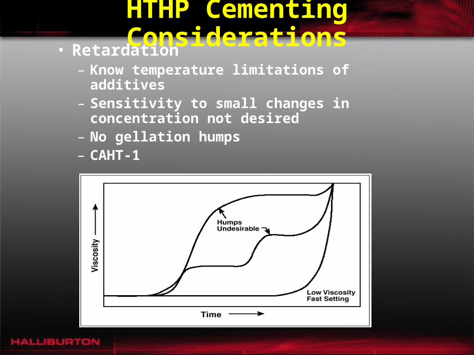
HTHP Cementing Considerations• Retardation
– Know temperature limitations of additives– Sensitivity to small changes in
concentration not desired– No gellation humps– CAHT-1

HTHP Cementing Considerations• Strength Stability
– Above 230 °F , SSA-1 or SSA-2 must be added to prevent strength retrogression.

HTHP Cementing Considerations• Viscosity/Suspension
– Thermal thinning occurs as temperature increases– Slurry must have sufficient viscosity at BHCT to
suspend solids– In critical applications slurry should have no free water.– Adequate viscosity at BHCT may result in high surface
viscosity– Smaller particle size additives suspend easier but may
increase mixing viscosity (ex. SSA-1, MicroMax, HI-DENSE #4)

HTHP Cementing Considerations
• Filtration Control– Normal fluid loss guidelines apply– Know temperature limitations of
additives

HTHP Cementing Considerations
• Gas Migration– GasStop HT Gas Migration Control
Additive• Controls gel strength development
from 200-350 °F• Controls fluid loss up to 500 °F

Strength Stabilizing Additives• SSA-1 (Silica Flour)
– Fine silica– Prevents strength retrogression– 35% (or greater) when BHST’s > 230 °F– Better suspension
• SSA-2 (Oklahoma No. 1)– Coarse silica– Same application as SSA-1 – Heavy weight applications
• SSA-1 (Silica Flour)– Fine silica– Prevents strength retrogression– 35% (or greater) when BHST’s > 230 °F– Better suspension
• SSA-2 (Oklahoma No. 1)– Coarse silica– Same application as SSA-1 – Heavy weight applications
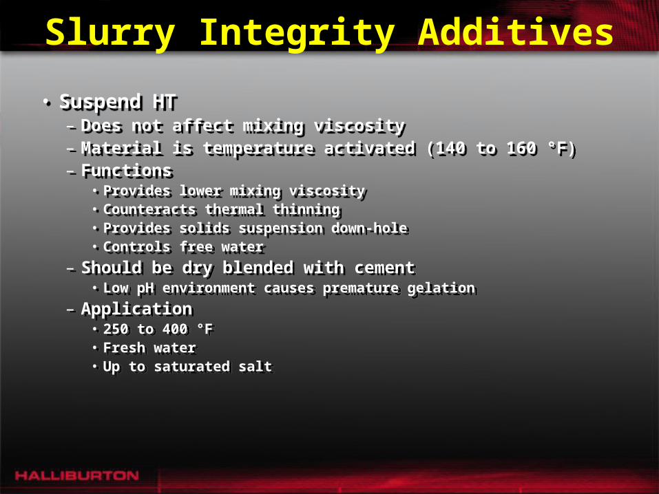
Slurry Integrity Additives
• Suspend HT– Does not affect mixing viscosity– Material is temperature activated (140 to 160 °F)– Functions
• Provides lower mixing viscosity• Counteracts thermal thinning • Provides solids suspension down-hole• Controls free water
– Should be dry blended with cement • Low pH environment causes premature gelation
– Application• 250 to 400 °F• Fresh water• Up to saturated salt

Slurry Integrity Additives
• Silicalite • Silicalite 97L
–Liquid Silicalite –50% active aqueous suspension
• Silicalite • Silicalite 97L
–Liquid Silicalite –50% active aqueous suspension

Slurry Integrity Additives
• GasCon 469– 15% active aqueous suspension– Imparts thixotropic properties
to slurry – 40 to 250 °F – GasCon 469 Winterized (when
stored < 40 °F)
• GasCon 469– 15% active aqueous suspension– Imparts thixotropic properties
to slurry – 40 to 250 °F – GasCon 469 Winterized (when
stored < 40 °F)

Slurry Integrity Additives
• Microblock– 50% active aqueous suspension– Imparts thixotropic properties
to slurry– Extender for light weight
cements– 60 to 400 °F
• Microblock– 50% active aqueous suspension– Imparts thixotropic properties
to slurry– Extender for light weight
cements– 60 to 400 °F

Slurry Integrity Additives• FWCA (WG-17)
– Free water control agent– Prevents solids segregation– Increases mixing viscosity– 80 to 200 °F (mild retarder)
• Bentonite• Attapulgite• ECONOLITE
• FWCA (WG-17)– Free water control agent– Prevents solids segregation– Increases mixing viscosity– 80 to 200 °F (mild retarder)
• Bentonite• Attapulgite• ECONOLITE

Flow Through Unset Cement
• Mechanism
• Characteristics
• Solutions
• Mechanism
• Characteristics
• Solutions

Hydrostatic Pressure Loss
CementFluid
CementGels
CementHardens
CementSets
Formation Gas Pressure
OverbalancePressure
Time
Hyd
rost
atic
Pre
ssu
re

Gas ChannelFormation
• Cement slurry placed
• Slurry behaves as a fluid
• Transmits full hydrostatic pressure
• Cement slurry placed
• Slurry behaves as a fluid
• Transmits full hydrostatic pressure
Permeable Zone
Gas Zone

Gas ChannelFormation
• Static gel strength devel-opment begins
• Fluid loss to formations
• Volume reduction causes pres-sure loss
• Static gel strength devel-opment begins
• Fluid loss to formations
• Volume reduction causes pres-sure loss
FiltrateLoss

Gas ChannelFormation
• Overbalance Pressure is lost
• Fluid loss continues in lower pressure zone
• Gas enters wellbore and percolates up annulus
• Overbalance Pressure is lost
• Fluid loss continues in lower pressure zone
• Gas enters wellbore and percolates up annulus
FluidLoss
GasEntry

Gas ChannelFormation
• Percolation leads to gas channel formation
• Permanent channel left after cement sets
• Percolation leads to gas channel formation
• Permanent channel left after cement sets
GasChannel

Gas Migration Through Unset Cement
• Laboratory testing was conducted with SGS effects and fluid loss simulation
• Channels were found in set samples of cement slurries in which gas migration occurred
• Laboratory testing was conducted with SGS effects and fluid loss simulation
• Channels were found in set samples of cement slurries in which gas migration occurred

Overbalance Pressure Is Lost Due To The
Combined Effects Of:1. Static Gel Strength2. Volume Loss
1. Static Gel Strength2. Volume Loss

Potential Pressure Loss Due to Static Gel Strength
P = (SGS / 300) x (L / D)P = (SGS / 300) x (L / D)

Static Gel Strength is the Internally Developed
Rigidity Within the Matrix Which Resists Forces
Placed Upon It

Actual Pressure Loss Is Not Caused By Static Gel Strength Alone. It Must Be Accompanied
By Volume Loss

Potential Pressure Loss Due to Volume Loss
P =P = V / CF V / CF

Volume Loss Due to Pressure Loss• Small volume loss from
a pressurized hydraulic system will cause a very large pressure loss
• Since cement slurry is incompressible (“dirt” and “water”), a small volume loss will cause a large pressure loss
• Small volume loss from a pressurized hydraulic system will cause a very large pressure loss
• Since cement slurry is incompressible (“dirt” and “water”), a small volume loss will cause a large pressure loss

∆P(SGS)
0 psi
1000 psi
∆P(SGS)
0 psi
1000 psi
Actual Pressure LossActual Pressure Loss
Actual Pressure Loss
0 psi
0 psi
Actual Pressure Loss
0 psi
0 psi
P(VL)
1000 psi
0 psi

Maximum SGS for Gas Flow
0
100
200
300
400
500
0 20 40 60 80
Time (minutes)
Sta
tic
Gel
Str
eng
th (
lbs/
100
ft2)
No Gas flow
Gas Flow

Flow Potential Factor
FPF = MPR / OBP
MPR = (500 / 300) x (L / D)
FPF = MPR / OBP
MPR = (500 / 300) x (L / D)

GAS FLOW POTENTIALGAS FLOW POTENTIAL
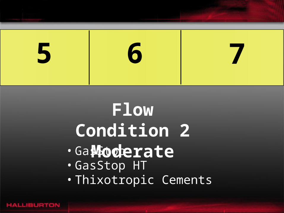
< 0 0 – 1 1 – 4 5 – 7 8 – 15 > 15
Blowout Negligible RedesignFlow Condition 1
“Minor”
Flow Condition 2
“Moderate”
Flow Condition 3
“Severe”
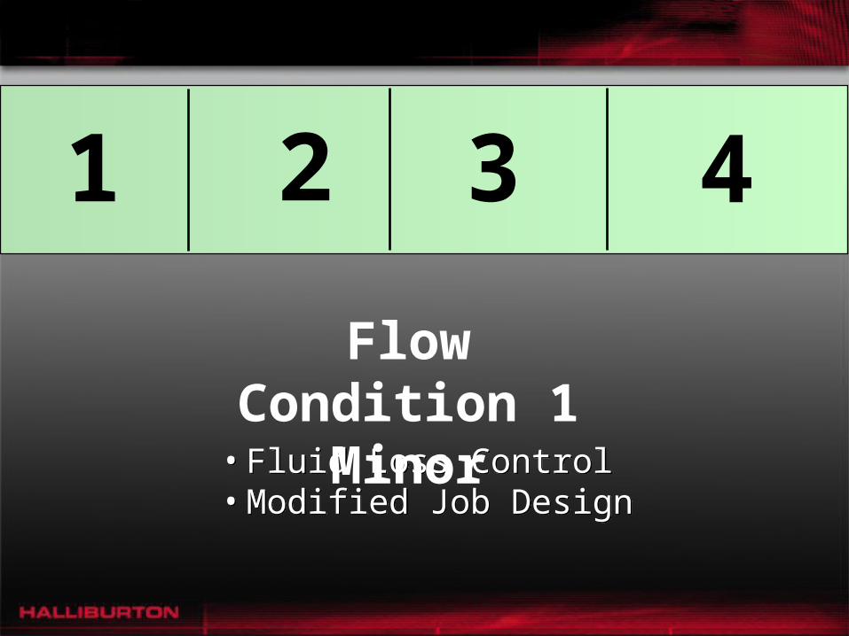
• Fluid Loss Control• Modified Job Design• Fluid Loss Control• Modified Job Design
1 2 3 4
Flow Condition 1Minor

Minor GFP Solutions
Limits Volume Reduction
Lowers GFP by use ofbackpressure, shortenedcement column, and otherparameters
Limits Volume Reduction
Lowers GFP by use ofbackpressure, shortenedcement column, and otherparameters
Fluid Loss Control:
Modified Job Design:
Fluid Loss Control:
Modified Job Design:
• GasStop• GasStop HT• Thixotropic Cements
• GasStop• GasStop HT• Thixotropic Cements
Flow Condition 2Moderate
5 6 7

Moderate GFP Solutions
Delayed Gel Strength
(in a static environment):
Thixotropic Cements:
Delayed Gel Strength
(in a static environment):
Thixotropic Cements:
Delays Gel Strength withRapid Transition Time
Rapid Gel Strengthminimizes time for gasto percolate in annulus

Thixotropic CementThixotropic Cement
0
100
200
300
400
500
600
0 20 40 60 80
Tim e (m in)
Sta
tic
Gel
Str
eng
th
Normal Cement
Thixotropic Cement

0
100
200
300
400
500
600
0 0.5 1 1.5 2 2.5 3 3.5 4
Time (Hours)
Sta
tic G
el S
tren
gth
Delayed Gel Strengthand Fluid Loss
Delayed Gel Strengthand Fluid Loss
Normal Cement
Fluid Loss Rate
Gas Stop

• Super CBL• Foam Cement• Super CBL• Foam Cement
Flow Condition 3“Severe”
8 9 10 11 12 13 14 15
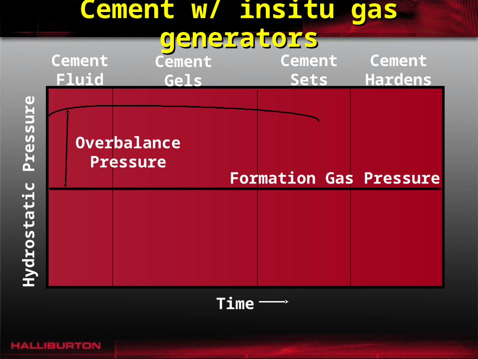
Cement w/ insitu gas generatorsCement w/ insitu gas generatorsCement
FluidCement
GelsCementHardens
CementSets
Formation Gas Pressure
OverbalancePressure
Time
Hyd
rost
atic
Pre
ssu
re

Halliburton Gas Flow Solutions
Minor GFPMinor GFPModerate GFPModerate GFP
Severe GFPSevere GFP

Thermalock
• Non-Portland cement that can be used in high CO2 concentrations, corrosive, geothermal and thermal environments.
• Blend of high alumina cement, flyash, and a phosphate containing compound.
• Can be used at BHST’s up to 700 degs. F and retarded to BHCT’s of 240 degs. F.
• Non-Portland cement that can be used in high CO2 concentrations, corrosive, geothermal and thermal environments.
• Blend of high alumina cement, flyash, and a phosphate containing compound.
• Can be used at BHST’s up to 700 degs. F and retarded to BHCT’s of 240 degs. F.