04_drilling process modelling using sph
DESCRIPTION
cae sphTRANSCRIPT
7/17/2019 04_Drilling Process Modelling Using SPH
http://slidepdf.com/reader/full/04drilling-process-modelling-using-sph 1/6
© 2013 Copyright by Arup
Drilling process modelling using SPH
Virginija GylieneVytautas Ostasevicius
Martynas Ubartas
Department of Engineering DesignFaculty of Mechanical Engineering and Mechatronics
Kaunas University of Technology, Lithuania
1 Introduction
Numerical methods became a powerful tool to understand such complicated process as cutting
processes. Based on finite element techniques, firstly a big challenge – geometric modeling of bodiescoming in contact interaction and mesh size/zone choice and creation. Secondly, today’s we now thatfinite element modeling is sure tool in the research of cutting processes after many series ofexperiments. So, here is the purpose to get reliable solution more quickly.
The latest versions of LS-DYNA® present the possibilities of Smooth Particle Hydrodynamics
(SPH) method. This method was used in 3D drilling process modeling. Solution was done assuminghigh impact contact interaction, when cutting tool was assumed as non-deformable rigid tool, made ofsolid elements and work-piece consisted of particles instead of elements. SPH model was created bySPH generation interface from solid nodes.
The papers will presents some aspects of multi edge cutting process modeling (drilling) usingSPH method, as contact definition and SPH control. Either work-piece failure by tool motion (feed androtation) was generated. So, two movement laws were defined. Firstly, the understanding of SPHmethod also is desirable for its appreciation that this method is “natural” considering the chipseparation process. Secondly, this method is so-called as “fast” method as concerns Kernel function.
These mentioned aspects were reason for the choice of SPH method for drilling processmodelling with the purpose in further analysis to apply ultrasonic excitation.
Firstly, the paper presents drilling experimental setup. Also the paper describes the techniquesof geometrical model generation using SPH particles. The techniques of modelling of high impactcontact interaction are presented.
2 Drilling experimental setup
Experiments were carried out by using YANG SMV 600 CNC milling machine using the drill
Guhring SL - GU 600 Bohrer, No 05519, D10. The special tool holder [1] with piezoceramics elements
for generating ultrasonic vibrations on the cutting edge of the drill 10 was created. For applied force
and applied torque measurements was KISTLER 9272 four components dynamometer platform used. All experimental setup is shown in Fig. 1. Cylindrical workpieces (Fig. 2 a)) fabricated from steel XC48
(170 HB) with length of 40 mm and diameter of 20 mm. were mounted in the clamping device of the
dynamometer, while the latter was installed on the desk (Fig. 2(b)).
During conventional and vibrational drilling process applied force and applied torque were measured,registered, and the signal was send to the computer. The signal was analysed using special softwarecreated by CTDEC (Centre Technique de l'Industrie du Décolletage).
9th European LS-DYNA Conference 2013
_________________________________________________________________________________
7/17/2019 04_Drilling Process Modelling Using SPH
http://slidepdf.com/reader/full/04drilling-process-modelling-using-sph 2/6
© 2013 Copyright by Arup
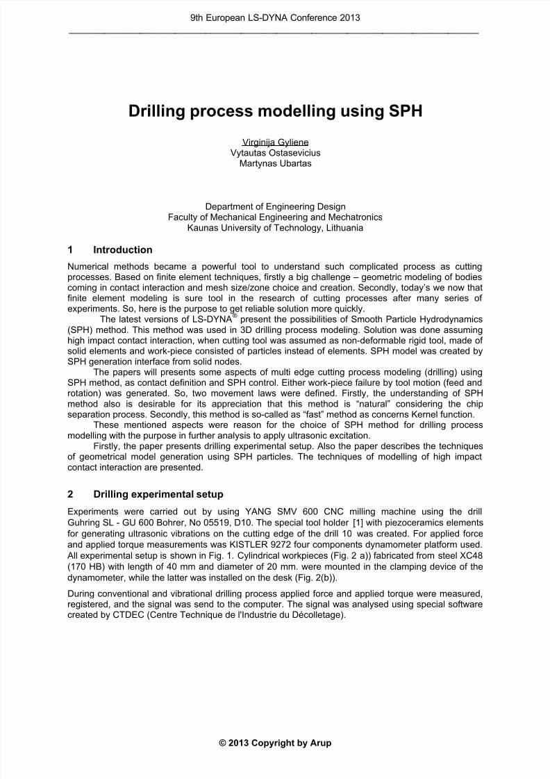
Fig.1: Scheme of the experimental setup for cutting force and torque measurements during drillingoperation: 1 – machine construction, 2 – desk, 3 – KISTLER dynamometer platform 9272, 4 –workpiece, 5 – vibration drilling tool, 6 – standard tool holder DIN 6359, 7 – drill tool, 8 – poweramplifier, 9 – high-frequency generator Agilent 33220A, 10 – controllers (KISTLER amplifier), 11 –computer.
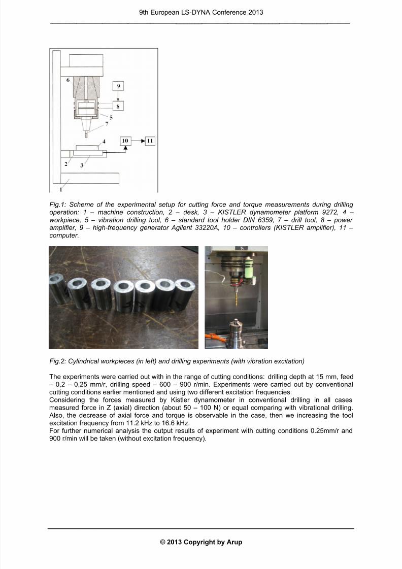
Fig.2: Cylindrical workpieces (in left) and drilling experiments (with vibration excitation)
The experiments were carried out with in the range of cutting conditions: drilling depth at 15 mm, feed – 0,2 – 0,25 mm/r, drilling speed – 600 – 900 r/min. Experiments were carried out by conventionalcutting conditions earlier mentioned and using two different excitation frequencies.
Considering the forces measured by Kistler dynamometer in conventional drilling in all casesmeasured force in Z (axial) direction (about 50 – 100 N) or equal comparing with vibrational drilling. Also, the decrease of axial force and torque is observable in the case, then we increasing the toolexcitation frequency from 11.2 kHz to 16.6 kHz.For further numerical analysis the output results of experiment with cutting conditions 0.25mm/r and900 r/min will be taken (without excitation frequency).
9th European LS-DYNA Conference 2013
_________________________________________________________________________________

7/17/2019 04_Drilling Process Modelling Using SPH
http://slidepdf.com/reader/full/04drilling-process-modelling-using-sph 3/6
© 2013 Copyright by Arup
3 Numerical modeling of cutting processes
Firstly, the research of the cutting process using numerical methods can replace very expensiveexperimentations, and the selection of the research level and methods depends on the obtainableparameters and computer equipment capabilities. From the other side, nowadays the research of onelevel done using finite elements method may replace experimentational research for the microscopiclevel. For example, comparisons with the experimental data at various cutting conditions prove thatthe proposed FEM model can accurately predict the critical surface microstructural attributes such asphase compositions, grain size, microhardness, and residual stress during hard turning of steel [2].
A large owerwiew of numerical modeling of cutting processes nowadays is made by Bagci [3]. As metal cutting is mainly a chip formation process, one of the most important considerations whenmodelling is the approach by which elements of the workpiece material separate as the cutteradvances [3]. In a numerical model of continuum, the material is discretised into finite sections overwhich, the conversion laws and constitutive equations are solved [3]. The way in which this spatialdiscretisation is performed leads to different numerical approaches. The approaches used are:Langrangian, Eulerian and Arbitrary Langrangian-Eulerian (ALE).
In the Langrangian approach, the numerical mesh moves and distorts with the physicalmaterial. So, Langrangian approach has artificial numerical tools to destroy the material as nodeseparation, element deletion and others. However, element distortion and deletion is not “natural” forcutting process.
Contrary, Eulerian finite element approach eliminate element distortion problems and createnew free surfaces without a special algorithm. This positive aspect of modelling demand some costsequally. Eulerian approach requires the knowledge of the chip geometry in advance, whichundoubtedly, restricts the range of cutting conditions capable of being analysed [3]. ALE techniquecombines the best features of the pure Langrangian analysis and Eulerian analysis [3]. Nowadays, itcan be proved, that chip formation in metal cutting is a major task of FEM software packages,assuming thermal, friction and impact effects in chip-tool interface. Due to these particularities (or non-satisfaction of results), so-called meshless, or meshfree methods have recently emerged. For,example Smooth Particle Hydrodynamic (SPH) is a modern effective technique to solve the problemsof high deformation. The main advantage of “fast” method is the use of Kernel function in particleapproximation. The Kernel function W is defined using the function θ by the relation [5]:
W(x, h) =1
h(x)d θ(x) (1)
Where d is the number of space dimensions and h is so-called smoothing length which varies in
time and in space. The SPH method is based on a quadrature formula for moving particles �() ∈ {1. . }, where () is the location of particle i, which moves along field v.
Then, particle approximation of a function can be defined by [5]:
Π () = ()� − , ℎ
=1 (2)
Where = is the “weight” of the particle. The weight of a particle varies proportionally to the
divergence of the flow.So, the method was developed to avoid the limitations of mesh tangling and distortion in extremedeformation problems with the Finite Element Method [4].
4 SPH model generation
A proper SPH mesh must satisfy the following conditions: it must be as regular as possible and mustnot contain too large variations [5]. For example, having cylindrical specimen, there is at least twopossibilities to perform the repartition of SPH particles.For that reason, the choice of rectangular body for geometrical body construction and particlegeneration is very convenient. There are at least three methods that can be used to build the mesh-
less models in SPH. Having the body which is called “volume” body (the case of the workpiece) theuse of solid elements for SPH generation is very useful.
9th European LS-DYNA Conference 2013
_________________________________________________________________________________

7/17/2019 04_Drilling Process Modelling Using SPH
http://slidepdf.com/reader/full/04drilling-process-modelling-using-sph 4/6
© 2013 Copyright by Arup
Workpiece was constructed by dimensions 14 ×14×10 mm. Block was meshed using SOLID164
elements (8 nodes with three degrees of freedom at each node in X, Y, Z directions). The meshing ofdrilling tool is performed in the same step (constructed in SolidWorks, cutted up to 30mm and importedin Ansys as Pre-Processor, and meshed by “tetrahedron free” Solid 164 elements).
In order to build SPH particles from meshed by solids bodies, drilling tool and workpiece aredefined as “PART”. In the next stage, SPH generation is performed from solid elements. Initially, we
have a set of particles with two kinds of properties: physical and geometrical properties [5]. Physicalproperties are defined in automatic SPH generation by assigning physical properties to “solid nodes”.This action automatically generates keyword ELEMENT_SPH. Geometrical SPH properties aregenerated in keyword SECTION_SPH. After SPH Part building, workpiece part, composed from solidelements must be deleted.
Drilling tool is built as rigid body and defined with keyword MAT_RIGID. This keyword allows usto define not only physical properties but also tool path. The definition of tool path demandssupplementary DEFINE_CURVE with movement law. Here you define the tool velocity, by defining thetime and displacement, for example. Each movement law is defined also byBOUNDARY_PRESCREIBED_MOTION_RIGID keyword, be defining the DOF.
The contact between SPH parts and shell or solids elements is alwaysCONTACT_AUTOMATIC_NODES_TO_SURFACE [6]. The essential purpose of this keyword is todefine the “slave” part and “master” part. Tool, a rigid body is defined as “master” part. Workpiece, a
deformable body is defined as “slave” part. However, for contact interaction the neighbour’s search ofSPH particle should be performed by using CONTROL_SPH. The parameter MEMORY is for adjustaccording the quantity of SPH particles (or by default). This variable defines the initial number ofneighbours per particle. The value can be positive, so the memory allocation is dynamic. And thevalue can be negative, so the memory allocation is static. So during the calculation only the closestSPH elements will be considered as neighbours. The number also can vary according to SPHparticles created in the model.
Some authors [7, 8] evaluated yet the influence of other artificial parameters, used in cuttingmodelling. It was noted that one of the most important parameter to adjust isCONTROL_BULK_VISCOSITY. Bulk viscosity is used to treat shock waves. A viscous term (called“Q”) is added to the pressure to smear the shock discontinuities into rapidly varying but continuoustransition regions. Artificial viscosity varies in the range of 0.06 till 1.0. The higher value is proposednamely for SPH modelling.
Most suitable material models, used for cutting modelling could be mentioned:MAT_PLASTIC_KINEMATIC (#3) AND MAT_JOHNSON_COOK (#015, #107 and #224). Namely, thenumbers in bracket show the capabilities to use SPH element.
MAT_PLASTIC_KINEMATIC material deformation law takes in account dynamic effects ofstrain rates which are taken into account by scaling static yield stress with the factor, assumed byCowper-Symonds relation. This law also takes in account the material failure criterion for materialdestruction (chip generation). However, the use of SPH method disengages the use of artificialparameters or empirically defined parameters in order to perform the chip generation. In this case SPHmethod is called the “natural” method.
Finally all package of general common keywords used in high velocity explicit analysis was writein input K file (PART, CONTROL_TERMINATION, DATABASE_BINARY_OPTION, SECTION andothers).
5 SPH modelling results
After generating SPH particles, the boundary conditions are imposed. BOUNDARY_SPC_SET is usedto eliminate DOF. In general all sides of workpiece are fixed. The best solution to fix the workpiece forfurther numerical analysis is the selection by “plan” (by defining three points) of SPH particles (bydistance 0.1). The units used for simulation: kN, GPa, kg, mm, ms.
5.1 Plate perforation by drilling tool
Considering that drilling tool is working with rotation and translational motion, first numerical study wasperformed according to bulge test. Drilling tool (used in the experiments) was used to perforate the
cooper plate (thickness 0.4 mm). The workpiece by dimensions 10×10×0.4 mm was modelled andmeshed (solid164 elements), which done 160 000 elements and 118803 nodes. After SPH generation
9th European LS-DYNA Conference 2013
_________________________________________________________________________________
7/17/2019 04_Drilling Process Modelling Using SPH
http://slidepdf.com/reader/full/04drilling-process-modelling-using-sph 5/6
© 2013 Copyright by Arup
plate was composed from 202005 particles (or the consistence up to 5000 particles per 1mm3). The
plate is fixed in two opposite sides.MAT_PLASTIC_KINEMATIC material deformation law was chosen with material characteristics [9](Density=8.93 kg/mm
3, Elastic modulus=110 GPa, Poisson’s Ratio=0.343, Yield Strength=33.3 MPa,
Tangent Modulus=210 MPa; without no strain rate effects, that is Cowper-Symonds constants).MAT_RIGID material deformation law was set to the drilling tool with characteristics: Density=13.300
kg/mm
3
, Elastic modulus=533 GPa, Poisson’s Ratio=0.24. Two part (plate + drilling tool) arepresented Fig.3. Due to publications [10], the transversal tool motion (100mm/min) was set to 8.35mm/s in order to avoid numerical instabilities. The input file presented all keywords mentioned earlier(With BULK_VISCOSITY: Q2=1, no SPH_CONTROL).
Against very high consistence of SPH particles, the translational force was about 1/3 according toidentical experiment (204 N reached in experiment).
a) Plate and drilling tool b) Cooper plate perforation by drilling tool
Fig.3: Plate perforation by drilling tool
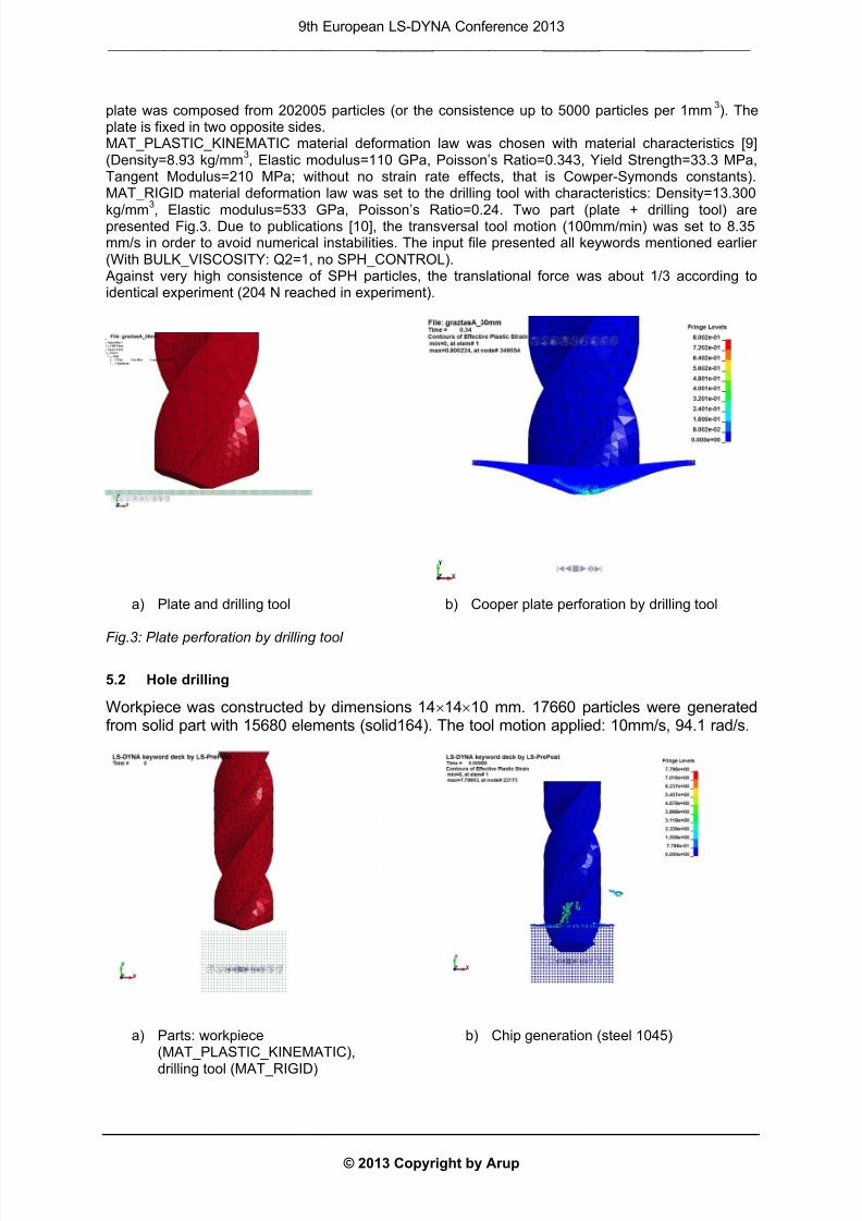
5.2 Hole drilling
Workpiece was constructed by dimensions 14×14×10 mm. 17660 particles were generatedfrom solid part with 15680 elements (solid164). The tool motion applied: 10mm/s, 94.1 rad/s.
a) Parts: workpiece(MAT_PLASTIC_KINEMATIC),
drilling tool (MAT_RIGID)
b) Chip generation (steel 1045)
9th European LS-DYNA Conference 2013
_________________________________________________________________________________

7/17/2019 04_Drilling Process Modelling Using SPH
http://slidepdf.com/reader/full/04drilling-process-modelling-using-sph 6/6
© 2013 Copyright by Arup
The first study of drilling process demonstrated that using SPH method, the chip removing process isvery “natural” and fast. In another case, it was noted, that the consistence of SPH particles ofworkpiece is not the main source of numerical instabilities in order to achieve the results, adequate tophysical process.
6 Summary
The paper presented the practical aspects in order to perform dynamic analysis of technologicalprocess (plate perforation by drilling tool, hole drilling) using SPH method.The parameter of artificial bulk viscosity in the use of SPH method demonstrated the most significantinfluence on the chip formation.However the research of allocation of memory for neighbours search of particles demandsupplementary study, in the case of high consistence of particles.
Against all parameters, mentioned in the literature concerning solution instabilities, the methodologydemands some complimentary study, concerning the consistence of particles (firstly, aspect ofvisibility), concerning the thermal effects (using Johnson-Cook law) and concerning particleapproximation form. Some numerical instabilities found in the research can be provided from the 3Dproblem.However, notably the choice of SPH methodology firstly is to use the SPH method in the aim to avoid
generals simplifications, which are usually applied in numerical study of cutting process.In the further research the attractable possibility should be to use the SPH method for ultrasonicallyassisted modelling.
7 References
[1] Jūrėnas, V., Skiedraitė, I., Bubulis, A., Graževičiūtė, J., Ostaševičius, V: "Tool JAW withultrasonic transducer", Lithuanian patent No. LT 5586 B, 2007.
[2] Ding, H., Shin, Y. C: “Multi-physics modeling and simulations of surface microstructurealterationin hard turning”, Journal of Materials Processing Technology, 2013, vol. 213, no. 6, p.877–886.
[3] Bagci, E: “3-D numerical analysis of orthogonal cutting process via mesh-free method”,International Journal of the Physical Sciences, 2011, vol. 6, no. 6, p. 1267–1282.
[4] Morten Villumsen, F., Torben Fauerholdt, G: “Simulation of metal cutting using Smooth ParticleHydrodynamics”, LS-DYNA Anwenderforum, Bamberg 2008, p. 1–20.
[5] Hallquist, J.: “LS-DYNA Theory manual”, Livermore software technology corporation, 2006,ISBN 0-977-8540-0-0.
[6] Shah, Q., Hasan, A.: “LS-DYNA for Beginners. An insight into Ls-Prepost and Ls-Dyna”, LAPLAMBERT Academic Publishing, 2012, p. 144.
[7] Schewer, L: “Aluminum plate perforation: A comparative case study using Lagrange withErosion, Multi-material ALE, and Smooth Particle Hydrodynamics”, 7
th European LS-DYNA
Conference, p. 1-28.[8] Limido, J., Espinosa, C., Salaün, M., Lacome J. L: „SPH method applied to high speed cutting
modelling“, Int. J. Mech. Sci., vol. 49(7), 2007, p. 898–908.
[9] www.matweb.com [10] Limido J.: “Predictive modelling of high speed machining effect on the fatigue life of aeronautical
parts”, Theses, MEGEP, p.228.
9th European LS-DYNA Conference 2013
_________________________________________________________________________________