050-405 - glenair
TRANSCRIPT

16U2-4903
THIS COPYRIGHTED DOCUMENT IS THE PROPERTY OF GLENAIR, INC. AND IS FURNISHED ON THE CONDITION THAT IT IS NOT TO
BE DISCLOSED, REPRODUCED IN WHOLE OR IN PART, OR USED TO SOLICIT QUOTATIONS FROM COMPETITIVE SOURCES, OR USED
FOR MANUFACTURE BY ANYONE OTHER THAN GLENAIR, INC. WITHOUT WRITTEN PERMISSION FROM GLENAIR, INC. THE INFORMATION
HEREIN HAS BEEN DEVELOPED AT GLENAIR'S EXPENSE AND MAY BE USED FOR ENGINEERING EVALUATION AND INCORPORATION
INTO TECHNICAL SPECIFICATIONS AND OTHER DOCUMENTS WHICH SPECIFY PROCUREMENT OF PRODUCTS FROM GLENAIR, INC.
050-405 PRODUCT BRIEF
2 MHZ TO 3 GHZ PRINTED CIRCUIT BOARD (PCB) MOUNTED
RF-OVER-FIBER RECEIVER SMALL & COMPACT WITH RUGGED CONSTRUCTION FOR HARSH ENVIRONMENTS
REV DESCRIPTION DATE APPROVED
2 Preliminary, added I2C address and register 05/04/2017 RAS
3 Preliminary, updated PN ordering information
4 Edit description on header 09/19/2017 RAS/GC
5 Document update, including pictures 5/30/2018 RAS/GJP
©2017 Glenair, Inc. REV: 5 US Cage Code 06324 Printed in USA
GLENAIR, INC. ∙ 1211 AIR WAY ∙ GLENDALE, CA 91201-2497 ∙ TEL: 818-247-6000 ∙ FAX: 818-500-9912
www.glenair.com PAGE 2 of 8 E-mail: [email protected]
050-405 PRODUCT BRIEF
PCB Mount RF-over-Fiber Receiver
2 MHz – 3 GHz
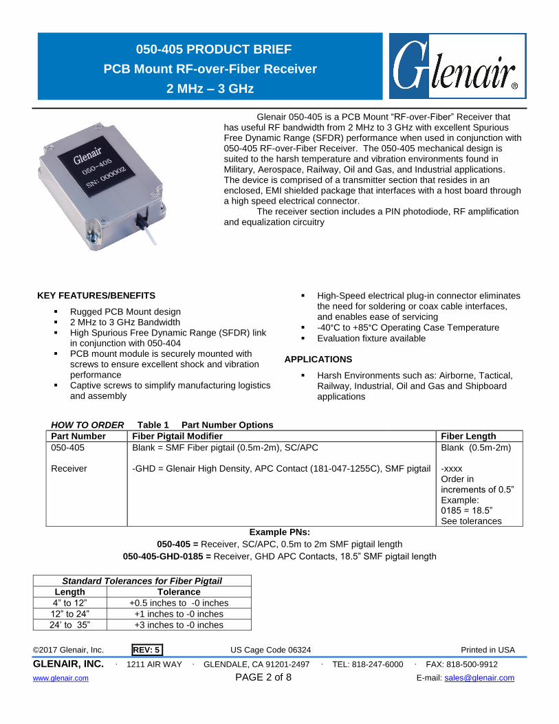
Glenair 050-405 is a PCB Mount “RF-over-Fiber” Receiver that has useful RF bandwidth from 2 MHz to 3 GHz with excellent Spurious Free Dynamic Range (SFDR) performance when used in conjunction with 050-405 RF-over-Fiber Receiver. The 050-405 mechanical design is suited to the harsh temperature and vibration environments found in Military, Aerospace, Railway, Oil and Gas, and Industrial applications. The device is comprised of a transmitter section that resides in an enclosed, EMI shielded package that interfaces with a host board through a high speed electrical connector. The receiver section includes a PIN photodiode, RF amplification and equalization circuitry
HOW TO ORDER Table 1 Part Number Options
Part Number Fiber Pigtail Modifier Fiber Length
050-405 Receiver
Blank = SMF Fiber pigtail (0.5m-2m), SC/APC -GHD = Glenair High Density, APC Contact (181-047-1255C), SMF pigtail
Blank (0.5m-2m) -xxxx Order in increments of 0.5” Example: 0185 = 18.5” See tolerances
Example PNs:
050-405 = Receiver, SC/APC, 0.5m to 2m SMF pigtail length
050-405-GHD-0185 = Receiver, GHD APC Contacts, 18.5” SMF pigtail length
KEY FEATURES/BENEFITS
Rugged PCB Mount design 2 MHz to 3 GHz Bandwidth High Spurious Free Dynamic Range (SFDR) link
in conjunction with 050-404 PCB mount module is securely mounted with
screws to ensure excellent shock and vibration performance
Captive screws to simplify manufacturing logistics and assembly
High-Speed electrical plug-in connector eliminates
the need for soldering or coax cable interfaces, and enables ease of servicing
-40°C to +85°C Operating Case Temperature
Evaluation fixture available
APPLICATIONS
Harsh Environments such as: Airborne, Tactical, Railway, Industrial, Oil and Gas and Shipboard applications
Standard Tolerances for Fiber Pigtail
Length Tolerance
4” to 12” +0.5 inches to -0 inches
12” to 24” +1 inches to -0 inches
24’ to 35” +3 inches to -0 inches

©2017 Glenair, Inc. REV: 5 US Cage Code 06324 Printed in USA
GLENAIR, INC. ∙ 1211 AIR WAY ∙ GLENDALE, CA 91201-2497 ∙ TEL: 818-247-6000 ∙ FAX: 818-500-9912
www.glenair.com PAGE 3 of 8 E-mail: [email protected]
050-405 PRODUCT BRIEF
PCB Mount RF-over-Fiber Receiver
2 MHz – 3 GHz
Functional Block Diagram
©2017 Glenair, Inc. REV: 5 US Cage Code 06324 Printed in USA
GLENAIR, INC. ∙ 1211 AIR WAY ∙ GLENDALE, CA 91201-2497 ∙ TEL: 818-247-6000 ∙ FAX: 818-500-9912
www.glenair.com PAGE 4 of 8 E-mail: [email protected]
050-405 PRODUCT BRIEF
PCB Mount RF-over-Fiber Receiver
2 MHz – 3 GHz
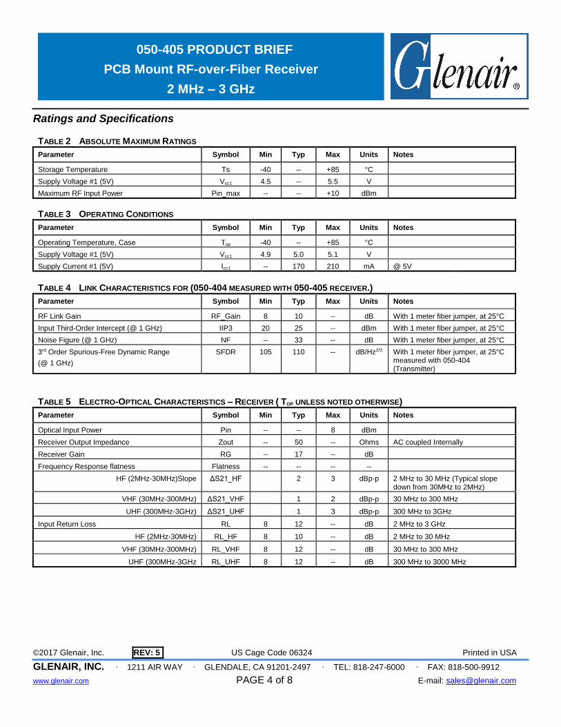
Ratings and Specifications
TABLE 2 ABSOLUTE MAXIMUM RATINGS
Parameter Symbol Min Typ Max Units Notes
Storage Temperature Ts -40 -- +85 °C
Supply Voltage #1 (5V) Vcc1 4.5 -- 5.5 V
Maximum RF Input Power Pin_max -- -- +10 dBm
TABLE 3 OPERATING CONDITIONS
Parameter Symbol Min Typ Max Units Notes
Operating Temperature, Case Top -40 -- +85 °C
Supply Voltage #1 (5V) Vcc1 4.9 5.0 5.1 V
Supply Current #1 (5V) Icc1 -- 170 210 mA @ 5V
TABLE 4 LINK CHARACTERISTICS FOR (050-404 MEASURED WITH 050-405 RECEIVER.)
Parameter Symbol Min Typ Max Units Notes
RF Link Gain RF_Gain 8 10 -- dB With 1 meter fiber jumper, at 25°C
Input Third-Order Intercept (@ 1 GHz) IIP3 20 25 -- dBm With 1 meter fiber jumper, at 25°C
Noise Figure (@ 1 GHz) NF -- 33 -- dB With 1 meter fiber jumper, at 25°C
3rd Order Spurious-Free Dynamic Range
(@ 1 GHz)
SFDR 105 110 -- dB/Hz2/3 With 1 meter fiber jumper, at 25°C measured with 050-404 (Transmitter)
TABLE 5 ELECTRO-OPTICAL CHARACTERISTICS – RECEIVER ( TOP UNLESS NOTED OTHERWISE)
Parameter Symbol Min Typ Max Units Notes
Optical Input Power Pin -- -- 8 dBm
Receiver Output Impedance Zout -- 50 -- Ohms AC coupled Internally
Receiver Gain RG -- 17 -- dB
Frequency Response flatness Flatness -- -- -- --
HF (2MHz-30MHz)Slope ΔS21_HF
2 3 dBp-p 2 MHz to 30 MHz (Typical slope down from 30MHz to 2MHz)
VHF (30MHz-300MHz) ΔS21_VHF 1 2 dBp-p 30 MHz to 300 MHz
UHF (300MHz-3GHz) ΔS21_UHF 1 3 dBp-p 300 MHz to 3GHz
Input Return Loss RL 8 12 -- dB 2 MHz to 3 GHz
HF (2MHz-30MHz) RL_HF 8 10 -- dB 2 MHz to 30 MHz
VHF (30MHz-300MHz) RL_VHF 8 12 -- dB 30 MHz to 300 MHz
UHF (300MHz-3GHz RL_UHF 8 12 -- dB 300 MHz to 3000 MHz

©2017 Glenair, Inc. REV: 5 US Cage Code 06324 Printed in USA
GLENAIR, INC. ∙ 1211 AIR WAY ∙ GLENDALE, CA 91201-2497 ∙ TEL: 818-247-6000 ∙ FAX: 818-500-9912
www.glenair.com PAGE 5 of 8 E-mail: [email protected]
050-405 PRODUCT BRIEF
PCB Mount RF-over-Fiber Receiver
2 MHz – 3 GHz
Ratings and Specifications (continued)
TABLE 6 COMPLIANCE SPECIFICATIONS (TO BE CONFIRMED)
CHARACTERISTIC Standard Condition Notes
Mechanical Shock MIL-STD-810 Para. 516.6, proc. I, 650g 0.9 ms operating
Mechanical Vibration MIL-STD-810 Para. 514.6, 40g rms Random, operating
ESD MIL-STD-883 1000V HBM
Flame Resistance MIL-STD-1344 Method 1012, Cond. B 30 seconds
Altitude
Altitude, 25Kft
Altitude, 70Kft
Decompression
Overpressure
RTCA DO160 G
Section 4.6.1 Category B1
Section 4.6.1 Category E1
Section 4.6.2 Category A2
Section 4.6.3 Category A1
Operating Altitude, 25,000 ft
Operating Altitude, 70,000 ft
Operating Altitude, 45,000 ft
28 psi
Damp Heat RTCA DO160G
MIL-STD-1344
Section 6 Category A
Method 1002.2, Cond. B
48 hours, Non-operational
10 cycles, 24 hours, Operational
Eye Safety IEC 60825-1:2007/
EN 60825-1:2007
Class 1M Laser Product

©2017 Glenair, Inc. REV: 5 US Cage Code 06324 Printed in USA
GLENAIR, INC. ∙ 1211 AIR WAY ∙ GLENDALE, CA 91201-2497 ∙ TEL: 818-247-6000 ∙ FAX: 818-500-9912
www.glenair.com PAGE 6 of 8 E-mail: [email protected]
050-405 PRODUCT BRIEF
PCB Mount RF-over-Fiber Receiver
2 MHz – 3 GHz
Table x Two-Wire interface ID: Data Fields – Address A2h
Byte # Decimal
Data Notes
0-95 Reserved
96 Temperature MSB (Note 1)
97 Temperature LSB (Note 1)
98 Vcc MSB (Note 2)
99 Vcc LSB (Note 2)
100 TX Bias MSB (Note 3) Not applicable
101 TX Bias LSB (Note 3) Not applicable
102 TX Power MSB (Note 4) Not applicable
103 TX Power LSB (Note 4) Not applicable
104 Rx Pavg MSB (Note 5 )
105 Rx Pavg LSB (Note 5)
105-255 Reserved Notes:
1. Temperature (Temp) is decoded as a 16 bit signed twos compliment integer in increments of 1/256 °C.
2. Supply voltage (VCC) is decoded as a 16 bit unsigned integer in increments of 100 μV.
3. Laser bias current (Tx Bias) is decoded as a 16 bit unsigned integer in increments of 2 μA.
4. Transmitted average optical power (Tx Pwr) is decoded as a 16 bit unsigned integer in increments of 0.1 μW.
5. Received average optical power (Rx Pwr) is decoded as a 16 bit unsigned integer in increments of 0.1 μW.
TABLE XX DIGITAL DIAGNOSTIC MONITOR CHARACTERISTICS (WHEN APPLICABLE) PARAMETER SYMBOL MIN. UNITS NOTES
Transceiver Internal Temperature Accuracy
TINT
±3.0
°C
Temperature is measured internal to the transceiver and is valid from -40°C to +85 °C case temperature
Transceiver Internal Supply Voltage accuracy
VINT
±0.1
V
Supply voltage is measured internal to the transceiver and can, with less accuracy, be correlated to the voltage at the Vcc pin. Valid over 5V ±5%
Transmitter Laser DC Bias Current Accuracy
IINT
±10
%
Transmitted Average Optical Output Power Accuracy
PT
±3.0
dB
Coupled into 9/125 mm MM fiber.
Received Average Optical Input Power Accuracy
PR
±3.0
dB
Coupled from 9/125 mm MM fiber

©2017 Glenair, Inc. REV: 5 US Cage Code 06324 Printed in USA
GLENAIR, INC. ∙ 1211 AIR WAY ∙ GLENDALE, CA 91201-2497 ∙ TEL: 818-247-6000 ∙ FAX: 818-500-9912
www.glenair.com PAGE 7 of 8 E-mail: [email protected]
050-405 PRODUCT BRIEF
PCB Mount RF-over-Fiber Receiver
2 MHz – 3 GHz
FIGURE 1 - OUTLINE DRAWING CONTINUED (MARKING)
LABELING:
Each unit will be shipped in an antistatic bag. The label on the antistatic bag shall be at a minimum Arial size 10 black font and contain at a minimum the following information:
ANTISTATIC BAG LABEL: Glenair Cage Code (06324) Part Number (PN 050-xxx as required) Date Code (DC xxxx) Serial Number (SN 123456)
Each unit will be marked, either with a label or laser engraving, as follows:
Marking font to be Arial, greater than .08 inches in height.
Marking: FIRST LINE OF TEXT
Glenair
Serial Number (6 digits) SECOND LINE OF TEXT:
Part number
Example:
GLENAIR SN123456
050-405

©2017 Glenair, Inc. REV: 5 US Cage Code 06324 Printed in USA
GLENAIR, INC. ∙ 1211 AIR WAY ∙ GLENDALE, CA 91201-2497 ∙ TEL: 818-247-6000 ∙ FAX: 818-500-9912
www.glenair.com PAGE 8 of 8 E-mail: [email protected]
050-405 PRODUCT BRIEF
PCB Mount RF-over-Fiber Receiver
2 MHz – 3 GHz
ACCESSORIES
PCB Mount Threaded Insert Fastners, PN 050-00XX
KEY FEATURES
xxxxxxxx
xxxxxxxx
EVALUATION Boards, PN 050-0XXX-EVALBOARD
Include
PCBA evaluation board with SMA connectors?
DC banana plug cables
Fiber optic Test Cables