05/09/76 imperial iranian air force (iiaf) - faa.goviaff).pdf05/09/76 imperial iranian air force...
TRANSCRIPT

05/09/76 Imperial Iranian Air Force (IIAF)
Page 1 of 1NextPage LivePublish
2/12/2005http://hfskyway.faa.gov/NTSB/lpext.dll/NTSB/2f33?fn=document-frame.htm&f=templ...

Official Accident Report Index PageReport Number NTSS-AAR-78-12Report Title Investigation Report--Wing Failure of Boeing 747-131,
Near Madrid, Spain, May 9, 1976Report Date October 6, 1978Organization Name National Transportation Safety Board Bureau of
Technology Washington, D. C. 20594WUN 2479Sponsor Name NATIONAL TRANSPORTATION SAFETY BOARD
Washington, D. C. 20594Report Type Special Investigation Report May 9, 1976Distribution Status This document is svailable to the public through the
National Technical Information Service, Springfield, Virginia 22151
Report Class UNCLASSIFIEDPg Class UNCLASSIFIEDPages 43Price H03.A01Keywords Aircraft accident; lightning strike; explosion; fuel
flameability; wing failure; gust overload; fuel ignition.Abstract On May 9, 1976, an Imperial Iranian Air Force Boeing
747-131 crashed as it approached Madrid, Spain. Witnesses observed lightning strike the aircraft followed by fire, explosion, and separation of the left wing. The report includes fire pattern studies, structural failure descriptions, trajectory analysis, fuel flammability calculations, gust loading analysis, and an analytical treatment of several hypotheses.
Page 1 of 1NextPage LivePublish
2/12/2005http://hfskyway.faa.gov/NTSB/lpext.dll/NTSB/2f33/2f34?f=templates&fn=document-f...

Facts of the AccidentAccident NTSB ID 78-12Airline Imperial Iranian Air Force (IIAF)Model aircraft 747-131 No. 5-283Year shipped Purchased from TWA 1976Aircraft manufacturer BoeingDate 05/09/76Time 1430Location Madrid, SpainCountry SPAFatalities 17Injuries -Fire during flight? YProbable cause Most probable sequence of events which culminated with
multiple structural failures and separation of the wing began with an ignition of the fuel vapors in the No. 1 fuel tank. The damage to the structure in the area of the tank provided positive indications of an explosion.
Contributing causes The possibility that the explosion was a secondary result of structural failure caused by excessive aerodynamic forces developed during high velocity gusts and turbulence cannot be completely dismissed; however, the evidence and the probabilities of an aircraft's encountering these unique environmental conditions make this hypothesis less supportable.
Weather conditions Thunderstorm activity, visibility goodTotal crew size 10Passengers 7Report ID NTSB-AAR-78-12Pages 38Day or night? DayFlight number ULF48Flight origin Teheran, IranFlight destination McGuire AFB, USADescription The aircraft crashed as it approached Madrid. Witnesses
observed lightning strike the aircraft followed by fire, explosion, and separation of the left wing.
Page 1 of 1NextPage LivePublish
2/12/2005http://hfskyway.faa.gov/NTSB/lpext.dll/NTSB/2f33/2f36?f=templates&fn=document-f...

NoticeTHIS DOCUMENT DETAILS THE FACTUAL FINDINGS OF SAFETY BOARD INVESTIGATORS WHO ASSISTED IN THE INVESTIGATION CONDUCTED BY THE IMPERIAL IRANIAN AIR FORCE. ANALYSIS IS LIMITED TO DEVELOPMENT OF ALTERNATE HYPOTHESE AS TO THE NATURE OF THE WING FAILURE BASED ON INVESTIGATIVE EVIDENCE, BUT THE SAFETY BOARD DID NOT CHOOSE BETWEEN THESE HYPOTHESES. THE BOARD DOES NOT DETERMINE THE PROBABLE CAUSE OR IDENTIFY CAUSAL AND CONTRIBUTING FACTORS BECAUSE IT HAS NO STATUTORY AUTHORITY TO DO SO.
Page 1 of 1NextPage LivePublish
2/12/2005http://hfskyway.faa.gov/NTSB/lpext.dll/NTSB/2f33/2f38?f=templates&fn=document-f...

IntroductionOn May 9, 1976, an Imperial Iranian Air Force (IIAF) B-747-131, Flight ULF48, crashed near Madrid, Spain. The aircraft was a military logistics flight en route to McGuire Air Force Base, U.S.A., from Teheran, Iran, with an intermediate stop at Madrid, Spain. The plane crashed during daylight at approximately 1430 G.m.t. while the aircraft was approaching Madrid. It was reported that the left wing had separated from the aircraft during flight. Since this was a military aircraft, neither the Convention on International Civil Aviation nor any of its Annexes applied to the investigation. Nevertheless, in a manner similar to that described in the ICAO Convention, the Spanish Government delegated the investigation to the Iranian Government.
Since the aircraft involved was a Boeing 747, a type used extensively in commerical operations worldwide, and, in view of the nature of the accident, the United States National Transportation Safety Board requested and was granted permission to assist in the investigation.
As the field phase of the investigation progressed, investigators realized that the determination of the cause of the wing failure would require extensive studies and examinations. An agreement was reached with the Governments involved to transport the left wing and engines to the United States where closer proximity of pertinent industry and necessary facilities would expedite the investigation. The wing was cut into manageable pieces and transported to the United States by the Iranian Air Force and commercial aircraft. The parts were fumigated at the port-of-entry and trucked to Atlantic City, New Jersey. The wing was reassembled in a mockup at the Federal Aviation Administration's National Aviation Facilities Experimental Center, Atlantic City, New Jersey.
The National Transportation Safety Board requested that the American aviation industry assist in the examination of the left wing. In a period of over a year the aviation industry provided 48 specialists with various engineering expertise, material and logistic support, extensive data, and special studies. The IIAF continued to supply support via flight test aircraft and participation in the wing and wing parts examinations.
The Federal Aviation Administration, the National Aeronautics and Space Administration, the U.S. Air Force, and the U.S. Army provided experts, special studies, materials, and logistic assistance. Various specialists, studies of CVR tapes, and operational information were provided by American Airlines, United Airlines, Pan American World Airways, Trans World Airlines, and the Air Line Pilots Association. The Fenwall Corporation, Pratt & Whitney Corporation, and the Minneapolis Eoneywall Corporation assisted in special examinations and research. Consultants were provided by the General Electric Company and the Batelle Institute. Specialists in aerodynamics, structures, and metals were provided by the Boeing Company, the Douglas Aircraft Corporation, Lockheed Georgia, and Lockheed California. These Government and industry personnel produced over 100 investigative reports.
Several hypotheses of possible causes of the wing failure are presented in this report. One hypothesis is that an explosion in a fuel tank destroyed the left wing and that lightning-strike currents ignited the tank explosion. Another credible hypothesis is that severe turbulence was encountered which caused the wing to fail as a result of structural overloads.
Page 1 of 1NextPage LivePublish
2/12/2005http://hfskyway.faa.gov/NTSB/lpext.dll/NTSB/2f33/2f3a?f=templates&fn=document-f...

Background Information
Page 1 of 1NextPage LivePublish
2/12/2005http://hfskyway.faa.gov/NTSB/lpext.dll/NTSB/2f33/2f41?f=templates&fn=document-f...

History of the Flight
On May 9, 1976, Imperial Iranian Air Force Flight 228, a Boeing 747-131, serial No. 5-283, was being operated as a military logistic flight from Teheran, Iran, to McGuire Air Force Base, New Jersey, with en route stop at Madrid, Spain.
The aircraft departed Merhabad Airport as Flight ULF48 at 08201 for Barajas Airport, Madrid, Spain, with 10 crevaembers and 7 passengers aboard. The estimated time of arrival was 1450. The planned flight altitude was flight level (FL) 330. At 1415, about 26 minutes before the accident, ULF48 gave an estinated time of arrival of 1440. At 1419, Madrid control issued a clearance to CPL VOR via Castejon and advised the flight that radar contact had been acquired.
At 1422 ULF48 was given the Madrid wasther. At 1425 Madrid control cleared ULF48 down to FL 100. ULF48 acknowledged and reported that he was leaving FL 270. At 1430 he advised Madrid that he was diverting to the left because of themderstorn activity, and at 1432 Madrid cleared ULF48 to 5,000 ft and directed his to contact Madrid approach control.
At 1433 the flightcrew of ULF48 contacted Madrid approach control and advised then that there was too much weather activity ahead and requested to be vectored around it. Madrid advised ULF48 of radar contact and asked confirmation of this request for vectors. The flightcrew confirmed their request and advised they were left of course and were going to CPL. Madrid advised ULF48 to proceed on a heading of 260°. The crew acknowledged the heading and informed Madrid that they were descending to 5,000 ft. This was the last radio contact with ULF48 although Madrid made several attempts for further contact. The aircraft crashed on farmland at an elevation of 3,000 ft m.s.1.
Page 1 of 1NextPage LivePublish
2/12/2005http://hfskyway.faa.gov/NTSB/lpext.dll/NTSB/2f33/2f41/2f42?f=templates&fn=docu...

Aircraft Information
The aircraft was purchased from Trans World Airlines and delivered to the Imperial Iranian Air Force on March 1, 1976. Before delivery all Airworthiness Directives (AD) were complied with and a large cargo door was installed on the left side of the fuselage by the Boeing Company at Wichita, Kansas.
The aircraft was last inspected by the Imperial Iranian Air Force on May 4, 1976; the aircraft had accumulated 14 hours since that inspection Maintenance records for the aircraft were not available for specialists to review in the United States.
When ULF48 departed Teheran, its gross weight was 610,299 lbs, which included 254,600 lbs of fuel, a mixture of JP-4 and jet-A types. The center of gravity was within allowable limits.
Page 1 of 1NextPage LivePublish
2/12/2005http://hfskyway.faa.gov/NTSB/lpext.dll/NTSB/2f33/2f41/2f47?f=templates&fn=docu...

Witness Observations and Weather
At the time of the accident the weather was cloudy with rain and lightning; visibility was good. Severe thunderstorms were in the area, and in fact, the day is remembered by local witnesses as "the day of the storm."
All witnesses were located south of Valdemoro and along the probable aircraft flightpath. At least two witnesses reported seeing lightning strike the aircraft. Some stated that they saw an in-flight fire confined to the No. 1 engine; others stated that they only saw the aircraft flying in and out of clouds. Those witnesses who reported seeing the in-flight explosion and fire followed by in-flight separation of parte, agreed that the time of occurrence was 1630 local, that the aircraft's altitude was about 6,000 ft above the ground, and that the aircraft's magnetic heading was about 220°.
There were no pilot weather reports, radar weather observations, or satellite weather observations available pertinent to the time and place of the accident. Surface and upper air charts for 1200, prepared by the Meteorological Analysis Center at Madrid, showed a closed low-pressure system that was centered over Spain.
Page 1 of 1NextPage LivePublish
2/12/2005http://hfskyway.faa.gov/NTSB/lpext.dll/NTSB/2f33/2f41/2f4b?f=templates&fn=docu...
Aircraft Wreckage
The wreckage was scattered over an area about 5 nmi long and 2 nmi wide on a heading of 220°. Three deposits of wreckage were situated within this area. The first wreckage deposit along the flightpath was 1.5 nmi wide and 2 nmi long. The following parts were found in this area: The left wingtip, several outboard aileron pieces, a section of leading edge, all of the aft upper wing skin, a section of fuel jettison line and two ribs from the No. 1 fuel tank, the high frequency antenna and coupler, a cargo light and a portion of skin from the leading edge of the vertical fin. The two ribs and the fuel line were located along the flightpath farthest from the main wreckage.
The second deposit of wreckage was about 4 nmi from the beginning of the wreckage path. This area contained parts of the forward upper left wing skin, No, 1 engine reverser sleeve and tail cone, and two krueger flaps.
One mile away from the second area and 5 miles from the first area, the third, and largest, impact site contained all four engines, the inboard section of the left wing, the fuselage, empennage, and the entire right wing.
Trajectory patterns could not be determined accurately because of the lack of wind data and exact flightpath. However, it was noted that a definite pattern existed in the location of materials at the first wreckage location. Heavy, dense units were to the right (north) and lighter units to the left (south) of the estimated flightpath.
All flight controls were accounted for. Wing leading edge devices and trailing edge flaps were retracted. The nose and main landing gears were retracted.
Pitting and localized burn areas typical of lightning attachment damage were found on the left wingtip and on the vertical fin at the VOR antenna. The left wing had separated into 15 major pieces before ground impact and parts of it were found at each location of wreckage. (See drawing on page 31.)
A 20-ft section of the left wingtip was in the first wreckage area. It had broken away from the wing in a positive (upward) bending direction. A localized area of fire damage was found in the surge tank, which was situated within the wingtip.
A 12-ft length of wing leading edge normally located just inboard of the separated tip was also found in the first wreckage area; it was not burned. Sections of the outboard aileron in this same area of wreckage were heat damaged. No ground fire existed about the burned wing parts.
The right wing and empennage were found complete in the third and final wrekage area. The right wing and aft fuselage and empennage were fire damaged, and ground fire had existed about the wing area. The wing was complete and attached to the fuselage.
Page 1 of 1NextPage LivePublish
2/12/2005http://hfskyway.faa.gov/NTSB/lpext.dll/NTSB/2f33/2f41/2f4f?f=templates&fn=docum...

Cockpit Voice Recorder
The CVR showed that the IIAF crew was aware of thunderstorm activity ahead of the flightpath and that ATC radar at Madrid had provided navigation information to steer around it. The captain remarked that the thunderstorm ahead "would tear us apart" if they entered it. Except for these events concerning the weather ahead, the flight deck crew appeared not too concerned about the situation. No sounds associated with turbulence were detected on the tape before the beginning of what can be called "significant" events. An exclamation that, "We're in the soup!" is the first indication of difficulties. Approximately 3 seconds later an electrical transient occurred on the tape which was interpreted as indicating that the aircraft was struck by lightning. An explosion occurred 0.2 seconds after the electrical transient. A sound interpreted as chunder was heard before the explosion. Simultaneous with the sound of the explosion two other events begin to record on the tape. One is a disturbance in the frequency of an engine-driven electrical generator. The frequency is normally 400 cps but an additional frequency of 28 Hz is impressed on the voltage which gradually increases to approximately 80 Hz.
The second event is the beginning of a chirping sound picked up by the cockpit area microphone. The chirping sound is believed to have been caused by power levers vibrating on the center pedestal. The frequency of the chirping and the generator power line disturbance are similar. The disturbance and chirping continued for about 17 seconds.
Another sound, apparently also caused by an aircraft vibration, began 4.3 seconds after the electrical transient and lasted for 3 seconds. A member of the crew stated, "Watch your autopilot," which was followed by an autopilot disconnect sound. Then a period of relative calm lasted 24 seconds.
The captain then stated that "the flight control is not working!" The gear warning horn started to sound, and the recording ended 12 seconds later as a loud noise was recorded.
The elapsed time from the indication of the electrical transient until the recording ended was 54 seconds.
The electrical transient evident on the CVR was determined to strongly resemble electrical transients on other CVR's removed from aircraft known to have been struck by lightning. The transient was svident on all the recording charmels of the CVR. Since several of these charmels had no microphone input, the source of the transient was electrical. The character and parameters of the impulses determined that lightning had generated the transients recorded on the IIAF CVR tape.
Page 1 of 1NextPage LivePublish
2/12/2005http://hfskyway.faa.gov/NTSB/lpext.dll/NTSB/2f33/2f41/2f59?f=templates&fn=docu...

Examination Of Left Wing Structure
Page 1 of 1NextPage LivePublish
2/12/2005http://hfskyway.faa.gov/NTSB/lpext.dll/NTSB/2f33/2f60?f=templates&fn=document-f...

General
The Boeing 747 wing is constructed of three spars--front, mid, and rear. The midspar ends at the outboard engine rib. Ribs are fastened to the spars and stringers are attached to the ribs. The skin planking is fastened to the stringers, spar caps, and closure ribs. The leading and trailing edges are constructed predominantly of fiberglas.
No evidence of fatigue or corrosion was found. There was no evidence of prior damage of any kind.
An electric altimeter recovered from the wreckage indicated 6,000 ft. This instrument would remain fixed at its reading when electrical power failed. The end of the CVR recording is probably coincident with this power loss.
Page 1 of 1NextPage LivePublish
2/12/2005http://hfskyway.faa.gov/NTSB/lpext.dll/NTSB/2f33/2f60/2f61?f=templates&fn=docu...

Lines of Separation
The left wing outboard of the No. 1 engine position separated in three major pieces and along three lines of fracture. The left wingtip, a piece about 20 ft long, separated on a line parallel to the fuselage centerline and roughly halfway between the end of the wing and the No. 1 engine. A second line of separation was just outboard of the No. 1 engine and ran parallel to the rib centerlines. The third line of separation spanned between the first two and ran along the front spar. The wingtip, consisting of the high frequency antenna and coupler, also separated from the wing.
Page 1 of 1NextPage LivePublish
2/12/2005http://hfskyway.faa.gov/NTSB/lpext.dll/NTSB/2f33/2f60/2f65?f=templates&fn=docu...
Spar Failures
There were two failures in the front spar in this outer section of wing. The wingtip fracture line included a failure of the front spar at WS 1392. This spar failure resulted from bending; the relative direction of failure was down and forward. The second failure occurred at WS 1240 and was associated with the inboard line of separation. This fracture was induced by tension overload, a slight compression and bending were detected at the lower spar cap.
There were five fractures in the rear spar between the No. 1 engine rib and the tip. A large section of the spar was missing. The rear spar had fractured near where it joined the No. 1 engine rib where it was part of the inboard separation line. At this point, there was a bend in the spar which exceeded 180°. The spar had bent aft and then inboard; the axis of rocation was a line almost perpendicular to the wing surface. Farther outboard there were four additional fractures in the spar. About one-quarter of the spar was Missing fron just inboard of the wingtip separation line. At this line a section of rear spar had been broken dray. The aft end of the rib that had attached to this section of spar was bent in all outboard direction. Just outboard of the outermost rib in the wingtip, the rear spar was again broken and bends and kinks were visible in the adjacent jettison fuel line. Fire bad not damaged these sections of spars and ribs.
The outermost rib (WS 1363.2) was damaged on its upper cap. The cap buckled in compression and deflected downward into the web which was partially torn. Compression damages to this rib and the caps of the next four inboard ribs formed a line that ended at the front spar break and separation line of the wingtip.
Page 1 of 1NextPage LivePublish
2/12/2005http://hfskyway.faa.gov/NTSB/lpext.dll/NTSB/2f33/2f60/2f67?f=templates&fn=docu...

Wing Skin Planking
The bottom skin remained fairly intact on the outer wing section. The bottom skin plank was fractured by tension overload along the wingtip separation line.
The upper skin of the outer wing consisted mainly of the extension of a rectangular plank that covered the full span of the wing fron fuselage to tip. Metallurgical studies established that the first, or original, fracture in this plank was near the rear spar about 100 inches outboard of the inner line of separation. This fracture was induced by compression overload, and it extended from the rear spar forward almost to the forward edge of the plank and then ran both inboard and outboard. This fracture in the plank is saw-toothed in shape and both edges of the fracture are delaminated and bent upward. The plank had apparently broken when the wing was bent upward. The entire plank, except for two small pieces, was located in the first major wreckage area. The plank outboard of the No. 1 engine position had fractured into many pieces which, in general, were smaller than these pieces of the plant from inboard of the No. 1 engine. One large spanwise piece, about 32 ft long, was recovered. It apparently had been torn off the wing in a spanwise direction, continuous from about midway between the No. 1 and No. 2 engines outboard to the position of the original fracture in the plank, outboard of No. 1 engine. The piece was bent into a large "S" curve; it was bent upward at its position over the No. 1 fuel tank. This piece varied in width from a sharp point at the outboard end to almost the full panel width over the No. 1 tank. The front boundary of the piece was its finished edge which joined the front panel along the midspar line. Sections of the midspar cap remained attached to the plank at the No. 1 fuel tank location.
Page 1 of 1NextPage LivePublish
2/12/2005http://hfskyway.faa.gov/NTSB/lpext.dll/NTSB/2f33/2f60/2f6b?f=templates&fn=docu...

Outboard Aileron
Five pieces of outboard aileron were recovered from the first wreckage area. The inboard section was not found. There was some heat damage to the outermost piece of aileron. The fastener hole deformations at the outer hinge position were in an aft direction. Except for the most inboard balance, all other weights were attached to the aileron; the missing weight was not recovered.
Page 1 of 1NextPage LivePublish
2/12/2005http://hfskyway.faa.gov/NTSB/lpext.dll/NTSB/2f33/2f60/2f6e?f=templates&fn=docum...

Wingtip Skin
The outer end of the upper skin plank terminated at rib WS 1585.2. The tip itself was covered with honeycomb structure. At the junction of these two skins the fastener hole damages showed tension failures in both skins. The tip skin (honeycomb) was pulled outboard, and the skin plank had been pulled inboard. The cap of the front spar adjacent to this seam had been compressed and had broken. The web of the rib at this position had not buckled.
Page 1 of 1NextPage LivePublish
2/12/2005http://hfskyway.faa.gov/NTSB/lpext.dll/NTSB/2f33/2f60/2f70?f=templates&fn=docu...

Internal Wingtip Damages
The high frequency antenna probe, which is normally mounted at the outboard trailing edge of the wingtip, was found in the first wreckage area. The last 8-ft piece of probe had separated at the tip trailing edge. The separation fracture consisted of up, down, inboard, and outboard bends, and the lower surface of the fracture was brinnelled.
The antenna coupler and lightning arrester assembly had been mounted farther forward along the tip edge (the forward extension of the probe). This unit was also found detached and in the first wreckage area. It had been fastened to the outboard end of the rear spar and the fastener holes were deformed up, down, inboard, and outboard. The lightning arrester visual indicator showed no evidence of damage from lightning currents.
The fuel jettison pipe normally passed through rib WS 1548.2 and then, after a right angle turn aft, passed through the rear spar and overboard. The pipe was bent and split between its attachments to the rib and spar. Aft of the rear spar the pipe was twisted and deformed. The internal tip damage was apparently caused by oscillating wingtip deflections.
Page 1 of 1NextPage LivePublish
2/12/2005http://hfskyway.faa.gov/NTSB/lpext.dll/NTSB/2f33/2f60/2f72?f=templates&fn=docu...

Fire Patterns
Fire centers were located in the wingtip, in the outboard end of the No. 1 fuel tank, and the outboard end of the No. 2 fuel tank. These fire centers were independent and not interconnected. Each center contained electrical devices--fuel quantity measuring devices or fuel pumps.
At the [sic] fire area, there was no continuity between the isolated fire, heat, and soot damages in the forward part of the surge tank and the lightning burn damages at the outboard trailing edge of the wingtip. The separated section of leading edge just inboard of the wingtip had no fire, heat, or soot damage. The dry bay area, which is normally behind the separated leading edge, was heavily sooted but had not been damaged by heat.
The fire, heat, and soot damage in the reserve tank was random. The trailing edge and section of aileron behind this tank were free of fire damage. The front spar forward of this tank was fractured. The outboard end of the fracture was not damaged by fire, heat, or soot, but the inboard end was. It was concluded that the break in the front spar occurred before the fire damages and that the unburned section of aileron and trailing edge separated from the wing before the fire.
The aft outboard corner of the No. 1 tank was sooted and burned aft of the midspar. There was heavy fire damage to the trailing edge behind the tank. The nonmetallic leading edge forward of the No. 1 tank was heavily burned.
Fire had burned the No. 1 engine nacelle on the left side cowl near where it was separated from the pylon. The nacelle and pylon fracture faces were sooted. The upper pylon was heavily sooted on its inner and outer surfaces.
In the area of the No. 2 tank--the inner part of the wing--the fire, heat, and soot pattern indicated that a fuel fire had moved inboard behind the rear spar and along the trailing edge. At the wing root, the fire pattern extended fore and aft along the fuselage. The fuel for this fire obviously came from the No. 2 tank from which the upper wing skin cover plank was gone.
A soot pattern on the outboard side of the No. 2 engine nacelle extended aft from the firewall and became more intense as it progressed aft. An access panel was missing in the aft section of pylon, which influenced the pattern allowing soot to enter the pylon.
The examinations of the various patterns showed that all were influenced by fractures or distortions in the wing structure and engine/pylon mechanisms. Portions of outer wing had trailed behind the inner wing, which accounted for the unusual fire damage patterns.
Page 1 of 1NextPage LivePublish
2/12/2005http://hfskyway.faa.gov/NTSB/lpext.dll/NTSB/2f33/2f60/2f76?f=templates&fn=docu...

Damage Symmetry of No. 1 Fuel Tank
Although the upper skin plank was almost completely separated from stringers and spars, two relatively long sections of upper spar cap from the mid and rear spars remained attached to the skin plank on the inner surface at the curvature. Some sooting was visible on the inner surface of the curvature except for areas that had been covered by the stringers. Rubberized sealant material along the stringer-to-skin seam had been damaged by heat on its surface but not on the torn surface that became exposed after the separation.
Two ribs from the outboard end of the No. 1 tank were found separated from the wing structure and were located in the first deposit of wreckage along the flightpath. These ribs were normally located between the No. 1 engine nacelle rib and the flap track rib about 100 inches farther inboard. The nacelle rib formed the outboard closure end of the No. 1 tank. The following observations concern the wing structure in this area of the No. 1 tank.
The aft edge of the fractured midspar "T" cap remained attached to the skin plank. The forward edge of the fractured rear spar cap remained attached to the skin plank. The fractures in both cases were the result of bending loads, and both fractures originated at the radius at the intersection of the horizontal extension of the "T" and its downward extending leg.
In both cases, the direction of the bending loads indicated an upward rotating movement of the skin plank in relation to the spars and remaining portions of the "T" cap still attached to the spar. The fracture of the "T" cap originated at WS 1140 on the midspar and at WS 1140 and 1200 on the rear spar and proceeded inboard and outboard from these locations.
Two fittings that normally fasten a rib (WS 1140) to the mid and rear spar caps (and to the wing plank) were torn free of the rib and remained attached to the separated section of the "T" cap on the skin plank. The fastener holes in the fitting where it attached to the rib were deformed in an upward and forward direction at the rear spar and upward and aft at the midspar.
The nacelle rib and flap track rib are also attached by "T" sections directly to the skin plank. The inboard extension of the horizontal sections of the "T" of the nacelle rib fractured and remained attached to the skin plank. The outboard extension of the horizontal section of the "T" of the flap rib remained attached to the skin plank.
Fastener holes were deformed in the rib to stringer ties on ribs at WS 1140 and 1168 and the nacelle rib between the mid and rear spars. The deformations indicated that the upper forward section of ribs at WS 1140 and 1168 moved inboard and the upper forward section of the nacelle rib moved outboard relative to the common stringers. Ribs at WS 1140 and 1168 were recovered at the first wreckage location.
These observations indicate a symmetrical pattern of deformation of spar caps, fastener holes, and rib to skin ties. This pattern centered over the outboard rear corner of the No. 1 fuel tank.
Page 1 of 1NextPage LivePublish
2/12/2005http://hfskyway.faa.gov/NTSB/lpext.dll/NTSB/2f33/2f60/2f7f?f=templates&fn=docum...

Fuel and Fuel System
At the time of the accident the distribution of fuel was calculated to be as follows:
Tank Lbs
No. 1 Reserve 1,700
No. 1 Main 24,700
No. 2 Main 27,600
Center 6,000
No. 3 Main 27,600
No. 4 Main 24,700
No. 4 Reserve 1,700
Based on calculations supported by soot lines on the front spar, the outboard closure rib of the reserve tank would have been dry. In the No. 1 main tank, the bottom would have been covered by fuel out to WBL 800, or to WS 1168, at the rear spar to WS 1112 at the front spar. In the No. 2 main tank, the fuel would have covered the bottom to WBL 395, or WS 700, at the rear spar to WS 586 at the front spar.
Page 1 of 1NextPage LivePublish
2/12/2005http://hfskyway.faa.gov/NTSB/lpext.dll/NTSB/2f33/2f60/2f88?f=templates&fn=docu...

Fuel Tank Vent Ducts
Except for a portion of the No. 1 tank vent outboard of the No. 1 engine, most of the vent ducts were recovered. Crossover vents in the tanks were clear of heat indications and soot, except for the outboard crossover vent for the No. 1 tank which had been damaged severely by fire [sic] its forward end and was missing aft of the midspar.
Page 1 of 1NextPage LivePublish
2/12/2005http://hfskyway.faa.gov/NTSB/lpext.dll/NTSB/2f33/2f60/2f8c?f=templates&fn=docum...

Lightning Damage
Damages typical of lightning strike were found on the vertical fin and the left wingtip. A rivet on top of the VOR antenna had melted and resolidified, and one of the antenna connectors showed evidence of arcing. At the trailing edge of the left wingtip, the metallic portion of the outermost static discharger had melted and resolidified. The discharger was attached to a trailing edge strap, which bonded through a rivet to the rib immediately outboard of the jettison tube. The rivet was melted away, the fiberglas had carbonized, and the paint adjacent to the melted area had been discolored by heat. Small marks indicative of lightning impingement were visible on the leading edge of the wingtip. The whole aircraft wreckage was examined for lightning strike damage, but ground fire damage may have obliterated such evidence on many parts of the aircraft.
Page 1 of 1NextPage LivePublish
2/12/2005http://hfskyway.faa.gov/NTSB/lpext.dll/NTSB/2f33/2f60/2f8e?f=templates&fn=docum...

Engines, Nacelles, and Pylons
The usual indications of high-power operation were not evident on the rotating parts of the No. 1 and No. 2 engines. There was no evidence of foreign object impingement to either engine. There was no in-flight fire within either nacelle. Based on the condition of the turbine, compressor, fan blades, and engine cases, there was no in-flight engine failure. All fan blades were accounted for.
Both engine nacelles and struts had been subjected to severe dynamic loading. The fan on each engine had rubbed the fan case rub strip completely through to the metal case. The engine support structure was deformed by bending both in an inboard and outboard direction. The direction of fracture of the drag strut to wing attachment of the No. 1 engine was in an outboard direction.
Page 1 of 1NextPage LivePublish
2/12/2005http://hfskyway.faa.gov/NTSB/lpext.dll/NTSB/2f33/2f60/2f90?f=templates&fn=docu...

Tests And Research
Page 1 of 1NextPage LivePublish
2/12/2005http://hfskyway.faa.gov/NTSB/lpext.dll/NTSB/2f33/2f93?f=templates&fn=document-f...

Overfill Compensator
An isolated area of fire damage in the left wingtip surge tank appeared to be centered about an overfill compensator--a unit of the refueling system. A spark between elements of the overfill compensator was considered a possible source of fuel vapor ignition. Lightning currents flowing in aircraft skin and structure elements can induce some voltage in all of the electrical wiring enclosed in the aircraft. A series of tests were performed to find out the amount of voltage necessary to exceed the compensator breakdown voltages and thus create a spark. The compensator is a multicircuit device, and sparkovers occurred at 14 kilovolts in one circuit and at 6.9 kilovolts in another circuit. The actual lightning-induced voltages possible in the B-747 compensator circuits have not been determined, but marks and their locations left by the sparkovers in the test compensators were used to guide the examination of the recovered compensator from the Iranian B-747. Optical and electron microscopes were used to examine the compensator for sparkover spots; none were found. However, energy levels required to produce a spark will not necessarily damage metal or leave marks.
Page 1 of 1NextPage LivePublish
2/12/2005http://hfskyway.faa.gov/NTSB/lpext.dll/NTSB/2f33/2f93/2f94?f=templates&fn=docu...
Fuel Line Couplings and Related Parts
An electrical spark caused by lightning currents flowing through one of the fuel line couplings in the fuel tank plumbing was conjectured as a possible source of an explosion in the left wing. Laboratory tests showed that the couplings have intermittent electrical conductivity, which would make them capable of sparking when electrical currents were passed through them. Twenty-nine couplings were removed from tank areas of the left wing. Optical microscopes up to 70-power were used to inspect them, and no evidence of electrical sparking was found.
Page 1 of 1NextPage LivePublish
2/12/2005http://hfskyway.faa.gov/NTSB/lpext.dll/NTSB/2f33/2f93/2f96?f=templates&fn=docu...

Hotor-Operated Fuel Valve
Based on the fuel line coupling tests, no electrical conductivity existed between the drive shaft and the valve housing (into which the shaft extends) of the motor-operated gravity drain valve located at WS 1187 (aft end of No. 1 tank). The motor which operated this valve from the outside of the rear spar was not recovered and, therefore, was not available for inspection. Examinations determined that the valve shaft and the valve disc were electrically insulated from the assembly housing. These parts were examined thoroughly under optical and electron microscopes, and no marks indicative of electrical sparking were found.
Page 1 of 1NextPage LivePublish
2/12/2005http://hfskyway.faa.gov/NTSB/lpext.dll/NTSB/2f33/2f93/2f98?f=templates&fn=docu...

Residue Analysis
Federal Bureau of Investigation and Boeing Company laboratories analyzed eight samples of residue from the fuel tanks and dry bay areas. No evidence of explosives or explosive residues was found.
Page 1 of 1NextPage LivePublish
2/12/2005http://hfskyway.faa.gov/NTSB/lpext.dll/NTSB/2f33/2f93/2f9a?f=templates&fn=docum...

Electrical Bonding Measurements (Wingtip)
The electrical bonding within the wingtip was examined by a series of low resistance measurements to evaluate the electrical conductivity paths through the wingtip. The values were detemined to be within normal tolerance. There were no discontinuities.
Page 1 of 1NextPage LivePublish
2/12/2005http://hfskyway.faa.gov/NTSB/lpext.dll/NTSB/2f33/2f93/2f9c?f=templates&fn=docum...

Overpressure for Skin Loss Calculations
Of the two sections of upper wing skin, the aft mounted section was found in the first location of wreckage. It was fractured in many pieces. None of the stringers remained attached. Calculations showed that pressures from 37.4 psi to 47.7 psi would be required to separate stringer to rib attachments at any of the wing tank stations at 1.0g to 2.0g loads.
Page 1 of 1NextPage LivePublish
2/12/2005http://hfskyway.faa.gov/NTSB/lpext.dll/NTSB/2f33/2f93/2f9e?f=templates&fn=docum...

Eddy Current Conductivity Tests
The dry bay lower skin located between the surge tank and the reserve tank was heavily sooted, although the upper wing skin was not, and was separated from the dry bay area. Readings taken with an eddy current meter indicated conductivity in the normal range for this material; thus, there was no overheating of the skin.
Page 1 of 1NextPage LivePublish
2/12/2005http://hfskyway.faa.gov/NTSB/lpext.dll/NTSB/2f33/2f93/2fa0?f=templates&fn=docum...

Fuel Line Pressure Collapse Tests
A 2.5-inch diameter fuel jettison tube, normally located within the No. 1 fuel tank, was found free in the wreckage scatter attached to rib WS 1168. This tube was collapsed along 90 percent of its length. As stated previously, this was the first unit found along the wreckage path. The tube was not sooted, although the area of tank from which it cane was heavily sooted. External pressure tests were conducted on a section of similar tubing. A specimen of the tubing was mounted inside a pressure vessel, and pressure was increased in the chamber at a rate of 15 psi per minute until the tube failed. The tube collapsed along two-thirds of its length at 64 psi.
Two other ways to collapse the tube were considered. One way would be the application of combined bending and tension to the tube. The tension forces would have to be applied to the tube through the fuel line couplings. These couplings are predominantly pressure sealed and would not provide the mechanical strength to permit the required tension load to develop. A second way considered would be to place the tube under bending loads and then apply external pressure. Depending on the amount of bending applied, the pressure required could be as low as 20 psi. Except for pressures arising from an explosion in the tank, no known means of providing this pressure is available.
The failure mode of the specimen was similar to that found in the jettison tube. The collapsed tube and its location in the wreckage path supports the tank-explosion hypothesis.
Page 1 of 1NextPage LivePublish
2/12/2005http://hfskyway.faa.gov/NTSB/lpext.dll/NTSB/2f33/2f93/2fa2?f=templates&fn=docum...

Midspar Fuse Pin Tests
The outboard strut and nacelle (No. 1 engine) had separated from the wing, but the fuse pins, designed to prevent damage to the wing structure, had not functioned. The fuse pins were measured and tested and were found within specification. It was concluded that the loads that broke the strut, freeing the nacelle from the wing, were not in the pitch axis that would impose a threat to the wing box.
Page 1 of 1NextPage LivePublish
2/12/2005http://hfskyway.faa.gov/NTSB/lpext.dll/NTSB/2f33/2f93/2fa6?f=templates&fn=docum...

Surge Tank Protection System Tests
Tests determined that this system was functional, but it had not been activated.
Page 1 of 1NextPage LivePublish
2/12/2005http://hfskyway.faa.gov/NTSB/lpext.dll/NTSB/2f33/2f93/2fa8?f=templates&fn=docum...

Vent Channel Examination
The evidence gathered from examination of the vent ducts and upper wing skin established that flames did not travel between the surge tank and the No. 1 and the No. 2 main tanks.
Page 1 of 1NextPage LivePublish
2/12/2005http://hfskyway.faa.gov/NTSB/lpext.dll/NTSB/2f33/2f93/2faa?f=templates&fn=docum...

Residual Magnetic Field Measurements
In all metallic (hardened) parts, a residual magnetic field can exist because of environmental effects such as vibration, mechanical motion, shock, and lightning currents. The highest value of magnetic field strength measured on the left wing was at the outboard spoiler area (No. 1 and No. 2); this value was approximately 40 gauss. This measurement may indicate that the aircraft was struck by lightning of average intensity. These spoilers are located aft of the outboard end of the No. 1 fuel tank.
Page 1 of 1NextPage LivePublish
2/12/2005http://hfskyway.faa.gov/NTSB/lpext.dll/NTSB/2f33/2f93/2fac?f=templates&fn=docum...

Wing Skin Sample and Fuel Access Door Examinations
A small section of upper wing skin from above the No. 1 fuel tank was removed and examined microscopically. Hardness, conductivity, and microstructural evaluations indicated that the structural integrity of the aluminum was not impaired. The examinations concluded that the inner surface had been exposed to a flash of heat and smoke that advanced across the skin from forward to aft at a shallow angle. The flash occurred before the stringers separated from the skin. A transient flash was indicated since the primer was not damaged nor was the aluminum heat-treat condition affected. The heat was sufficient to cause some damage to the sealant as evidenced by the glazed sealant surface and its brittleness.
Two fuel access doors, No. 14 and No. 15, which were nounted in the lower skin beneath the No. 1 fuel tanks were measured and both displayed outward ballooning of the thin sections between the ribbed structure, a convex downward curvature of the ribbing, and a fracture of the sealing flange on the aft side of the doors. Tank access doors have been tested to pressures in excess of 80 psi in the fuel tank areas. They are not load bearing members of the wing. The damage indicates that the doors were fractured as a result of bending about the restrained flange.
The above observations support the hypothesis that an explosion occurred in the No. 1 fuel tank.
Page 1 of 1NextPage LivePublish
2/12/2005http://hfskyway.faa.gov/NTSB/lpext.dll/NTSB/2f33/2f93/2fae?f=templates&fn=docum...

Flammability Calculations - JP-4 Fuel
Calculations were based on temperature statistics for the Teheran-Madrid route, on calculated temperatures for the cruise altitude airspeed for 10,000 ft altitude near Madrid, and on fuel and ullage. The dynamics of the complex tank geometry were also considered. An assessment of flammability was then based on data taken from the Coordination Research Council Report, "Aviation Fuel Safety 1975." Calculations showed that the fuel-air mixture in portions of the ullage may have permitted ignition during the descent through 10,000 ft, and that a 4-millijoule spark would have provided sufficient energy to ignite the fuel. This level of spark energy will not necessarily leave physical evidence.
Page 1 of 1NextPage LivePublish
2/12/2005http://hfskyway.faa.gov/NTSB/lpext.dll/NTSB/2f33/2f93/2fb2?f=templates&fn=docu...

Forces Generated by Fuel Combustion
The following are pressures generated by ignited fuel consisting of 58 percent JP-4 and 42 percent JP-5 at different altitudes and fuel to air mixtures:
Fuel/Air Ratio
.04 .065 .130
Sea Level
PSI 87 114
7,000 ft
PSI 72 92 66
14,000 ft
PSI 58 72 53
These pressures are sufficient to cause the wing structure and component damages previously discussed.
Page 1 of 1NextPage LivePublish
2/12/2005http://hfskyway.faa.gov/NTSB/lpext.dll/NTSB/2f33/2f93/2fb4?f=templates&fn=docu...

Hypotheses Of Wing Failure CausesThe evidence obtained from the distribution of aircraft structure and witnesses' observations clearly indicate that the primary incident leading to total loss of the aircraft was the separation of its left wing while at au altitude of about 6,000 ft above the ground. The evidence supports the conclusion that the aircraft was in an area of severe weather characterized by thimderstorns with the associated turbulence and electrical activity. The goal of this investigation was to determine why the wing failed.
There were no clues provided from the conversation of the crew as recorded on the CVR, nor was any useful information provided by the FDR, because it was inoperative at the time of the accident. Therefore, the only useful evidence was the wreckage itself—its distribution and the nature of damages.
The examination of the recovered portions of the left wing disclosed that the major structure had failed at three separate spanwise locations and that all failures resulted from excessive loads. There was no evidence of prefailure damage, stress corrosion, or fatigue. Thus, studies were concentrated on the possible ways in which excessive loads can be applied. Thres hypotheses were considered by the investigative group in an effort to explain the initial and subsequent sequences of events which resulted in the multiple structural failures. They were as follows:
a. Internal overpressures--Loads resulting from an explosion or ignition of fuel vapors within the wing.
b. Aerodynamic forces--Loads developed by the wing's aerodynamic surface as the aircraft exceeds limit speeds through the air mass; loads developed as a result of an encounter with high velocity horizontal wind gusts, updrafts, or downdrafts; loads developed as a result of maneuvering the aircraft through pilot or autopilot control system inputs; or any combination of the above.
c. Dynamic forces--Loads developed when a structural body is excited to an undamped vibration at or near its natural frequency.
Page 1 of 1NextPage LivePublish
2/12/2005http://hfskyway.faa.gov/NTSB/lpext.dll/NTSB/2f33/2fb8?f=templates&fn=document-f...

Special Investigative Studies
Page 1 of 1NextPage LivePublish
2/12/2005http://hfskyway.faa.gov/NTSB/lpext.dll/NTSB/2f33/2fb8/2fbf?f=templates&fn=docum...

Analysis of Fuel Tank Area Damage
Consultants from various segments of industry participated in the detailed examination of the structural damage to areas near the wing fuel tanks. The expertise of these consultants varied widely and included structural design and loading, aeromechanics, thermodynamics, and explosion physics. Some of these persons had extensive experience in tests and research related to explosions and analysis of resultant damage.
The primary emphasis of this analysis was placed on the nature of the fractures, bends, and heat damage in and about the fuel tanks. Investigators sought to determine whether the magnitude and direction of the forces required to inflict such damage indicated the overpressure which would result from an ignition of the fuel vapors in the tank.
The consensus [sic] investigative group was that an explosion had occurred at or near to the aft outboard corner of the No. 1 fuel tank. The most convincing evidence of the overpressure was:
1. The symmetry of damage and the direction of the forces applied to closure ribs, spars, and skin, as indicated by the directions of the fractures, bends, and fastener-hole deformation.
2. The collapse of the fuel jettison tube located within the tank.
3. The pattern of the heat damage and soot on structure adjacent to the tank.The investigative group further concluded that the internal pressure required to inflict the damage could only have been developed if the structure enclosing the tank, including the skin planking, bad been intact when the explosion occurred.
Page 1 of 1NextPage LivePublish
2/12/2005http://hfskyway.faa.gov/NTSB/lpext.dll/NTSB/2f33/2fb8/2fc0?f=templates&fn=docum...

Analysis of Gust-Penetration Overload
Specialists of the National Aeronautics and Space Administration (NASA) evaluated possible sources of dynamic and static loads that could lead to wing failure. The major load sources considered were: Whirl mode flutter of the engine, fan stall excitation, engine fan surge, and atmospheric turbulence. Iightning was not studied as a source of loading. An examination of the wing damage and of previous theoretical work led the group to eliminate all but atmospheric turbulence. NASA concluded that turbulence caused the wing failure, either directly or in combination with some prior event which had weakened the wing structure, such as overpressurization of the fuel tanks or structural fatigue.
The NASA group considered passible ways that turbulence right cause the wing to fail. A conventional gust analysis, wherein only vertical gusts were considered, indicated that within the estimated speed range of the airplane the wing would stall before structural damage. However, an analysis of an inclined gust, involving both a vertical component and a headwind component, indicated that structural damage could occur before stall. Essentially, the head-on component causes an effective airspeed increase. An analysis was conducted to determine conbinations of different magnitudes of vertical and horizontal gusts which would produce aerodynamic loads in excess of the airplane's ultimate design loads. These results indicate that for level 1g flight, turbulence velocities of around 140 fps for both the vertical and headwind component were needed to cause structural failure. If the effective maneuver load factor is greater than 1g, as might be imposed by pullup or rolling maneuvers during turbulence, then the gust velocities to produce failure are reduced considerably--around 100 fps for an effective 2g condition.
On the basis of their investigation, the NASA group concluded that turbulence could have been a primary or contributing cause of the ultimate structural failure. Such a possibility appeared even more credible when the following factors were considered:
1. In thumderstorms, gust velocities from 100 to 150 fps were plausible; the horizoutal gust velocities can exceed the vertical velocities.
2. The analysis did not account for spanwise variation of gust velocities, which may aggravate the loads.
3. Dynamic amplification effects caused by the elasticity of the airplane were not considered.
4. Effects of load amplifications caused by sequential and reversed gusts were not included.The NASA specialists also considered the sequence of failure. They postulated that gust loads caused a localized failure in the skin or adjacent attachment rivets, and outlined a possible sequence of the progressive failure. The resultant failure pattern was shown to be somewhat similar to the fracture patterns found in the wreckage.
Page 1 of 1NextPage LivePublish
2/12/2005http://hfskyway.faa.gov/NTSB/lpext.dll/NTSB/2f33/2fb8/2fc8?f=templates&fn=docum...

Other Information
Page 1 of 1NextPage LivePublish
2/12/2005http://hfskyway.faa.gov/NTSB/lpext.dll/NTSB/2f33/2fb8/2fd1?f=templates&fn=docu...

Lightning Effects
Lightning currents flowing in the skin and structural elements of an aircraft can induce some level of voltage in all of the electrical wiring enclosed within the aircraft. The metallic structure of an aircraft acts as a conductor of the lightning stroke currents and prevents direct attachment to units enclosed by the metallic shield. The currents of the stroke generate magnetic fields while passing along this shell which, in turn, penetrate the metal shell and induce voltages and currents in elements within the shell. Experiments in the past have led to estimates that the highest level of induced voltage can be 1,000 to 2,000 volts.
Systems installed within a wing, such as fuel quantity measuring devices, fuel lines, and electrical wiring, will be subjected to induced voltages and currents. Discontinuities of various electrical paths within the wing can produce arcing of the induced voltages which could become ignition sources for a flammable fuel. As long as these induced currents are conducted along a continuous path through the wing and wing elements and eventually off the aircraft, no arcing should occur. Discontinuities are prevented at points where mechanical joints exist by electrical bonding or "jumpers" to assure conductivity. Fuel system components are located in zones in which the magnetic coupling effect is greatly reduced by the mass of the shielding structure and the geometry of the component's location.
Fiberglas components of the aircraft's structure include metallic strips which permit current to pass through the component and thus prevent discontinuities of the direct lightning strike current. Lightning strike tests on scale models pointed out the areas of the aircraft's geometry that were more susceptible to strike attachment. Such information helped to determine the location of components that were considered critical. Service experience also contributes to the design of lightning protection.
Page 1 of 1NextPage LivePublish
2/12/2005http://hfskyway.faa.gov/NTSB/lpext.dll/NTSB/2f33/2fb8/2fd2?f=templates&fn=docu...

Autopilot Information
The CVR tape contained sounds which could be the sutopilot disconnect warning. This airplane was equipped with a single-push operation auto-pilot disconnect at the time of delivery to TWA. In this configuration, when the pilot or copilot disconnects the autopilot using the control column disconnect button, there will be one or two flashes of the autopilot warning light and one or two cycles of the warning horn after release of the disconnect button.
The warning horn will sound also if the autopilot is disconnected by physically moving the autopilot engage switch to the OFF position, or if the autopilot automatically disengages. In either case, the warning horn will continue to sound until the pilot or copilot resets the warning system by either pressing the autopilot disengage button on the control wheel, or depressing the light plate on one of the two autopilot warning lights.
The autopilot will disconnect automatically under only two conditions: (1) If the INS Attitude Valid to the engaged autopilot channel is lost, (the INS attitude valid is a 28-volt d.c. output signal of the INS which indicates to the autopilot) or (2) if the electrical power is lost for more than 40 msec.
Page 1 of 1NextPage LivePublish
2/12/2005http://hfskyway.faa.gov/NTSB/lpext.dll/NTSB/2f33/2fb8/2fd6?f=templates&fn=docu...

Autopilot Design Considerations
An unwanted electrical input to the autopilot system as a result of lightning currents was theorized as a possible cause to produce wing structure overloads; the lightning currents would have caused a consequent autopilot adverse response. The 747 certification stated that an autopilot hardover loads analysis was made in compliance with FAA Advisory Circular No. 25.1329-1A. This analysis showed that the design loads of the aircraft could not be exceeded as a result of an autopilot input. The ailerons and spoilers were deflected to the maximum deflection allowed by the autopilot authority and by reacting the rolling moment by roll acceleration and roll damping as separate conditions. In addition, a checkback condition was analyzed by assuming that the airplane was rolled at the maximum roll rate obtainable from the autopilot, and the roll was checked by deflecting the ailerons and spoilers to the autopilot limits in the opposite direction, which produced a roll acceleration opposite the roll velocity. The airplane was assumed to be in level flight without pitch acceleration throughout the hardover roll maneuver. Structural loads were not exceeded.
Page 1 of 1NextPage LivePublish
2/12/2005http://hfskyway.faa.gov/NTSB/lpext.dll/NTSB/2f33/2fb8/2fda?f=templates&fn=docum...

Engine Fan Rub Vibrations
Early in the commercial service of the B-747 aircraft, the engine fan cowling rub strip was redesigned to prevent oscillations of the engine. Fan rub wear on the acoustical cowling strip led to fan-tip stall, which in turn resulted in engine vibrations. Several instances were recorded when this engine vibration was believed to have produced sufficient wingtip oscillations to cause the tip-mounted, high-frequency antenns to separate. The outer wing oscillatory frequency was estimated to be between 9 and 11 cycles per second. As a result of a test program, this phenomenon was corrected, and it has not occurred since.
A theory was developed that considered the engine fan rub, the engine mount damages, and the damage pattern of the wing outboard of the No. 1 engine position. It was proposed that, if the upper skin plank above and inboard of the No. 1 engine position had come loose for some reason, the aeroelastic properties of the wing and in particular the outboard section of wing, would be drastically changed. In addition, the loss of box structure integrity could lead to some loss of engine support which in turn resulted in fan rubbing and engine oscillations. According to this theory, the damages to the wingtip can be attributed to such oscillations. The overall conclusion would then be that the wing had not failed because of gusts or turbulence, but failed because of the original event in the wing box structure, which was caused by the loosening of the plank.
Page 1 of 1NextPage LivePublish
2/12/2005http://hfskyway.faa.gov/NTSB/lpext.dll/NTSB/2f33/2fb8/2fdc?f=templates&fn=docum...
ConclusionsAfter analyzing all of the available evidence, it is concluded that the most probable sequence of events which culminated with multiple structural failures and separation of the wing began with an ignition of the fuel vapors in the No. 1 fuel tank. The damage to the structure in the area of the tank provided positive indications of an explosion.
The possibility that the explosion was a secondary result of structural failure caused by excessive aerodynamic forces developed during high velocity gusts and turbulence cannot be completely dismissed; however, the evidence and the probabilities of an aircraft's encountering these unique environmental conditions make this hypothesis less supportable.
Page 1 of 1NextPage LivePublish
2/12/2005http://hfskyway.faa.gov/NTSB/lpext.dll/NTSB/2f33/2fdf?f=templates&fn=document-fr...

Ignition of Fuel Vapor in No. 1 Fuel Tank
By accepting the hypothesis that the explosion in the No. 1 tank was the first destructive event, the various wing failures can be explained as follows: The explosion failed the fasteners that held the stringers to the rib3 and the skin to the spars; the integrity of the aft wing box was lost as a result, which greatly reduced the torsional strength of the wing; and support of the No. 1 engine in the pitch plane also was lost. The fact that explosive forces could be developed in the tank verified that the wing skin forming the top of the tank was whole before the explosion. The probable sequence of wing destruction follows:
1. Overpressure was generated in the No. 1 fuel tank as a result of ignited fuel vapors. The location of this overpressure was the aft outboard corner of the tank adjacent to the closure rib or the nacelle rib.
2. Because of the overpressure, the upper skin panel, including stiffeners, pulled loose from ribs inboard of the nacelle rib and aft of the midspar. The stringer to rib fasteners separated by combined tension and shear, which resulted from the overpressure and subsequent inboard displacement of ribs at WS 1140 and WS 1168.
3. The inboard displacement of the ribs ruptured the rib attachments to the lower surface and spars, and the ribs became detached.
4. The upper skin panel billowed upward because of the explosion until bending fractures occurred at the mid and rear spars and the fasteners were sheared. The failure began at WS 1140 and progressed inboard and outboard from that position.
5. The upper skin shear tie attachments at the nacelle support rib and the flap track support rib fractured in bending because of the continued upward movement of the upper surface. The upper surface stiffener ties to the nacelle rib separated because of the outboard movement of the nacelle rib; the outboard movement was caused by the overpressure on the inboard side.
6. When the upper wing skin panel which was attached to the mid and rear spars separated, the aeroelastic properties of the wing, and especially the outboard section of wing were altered drastically.
7. The stiffness of the No. 1 engine mount was greatly reduced in the pitch axis by the loosening of the skin and the resultant loss of wing box integrity.
8. The loss of structural integrity of the wing box permitted increased torsional deflection of the wing.
9. The outer wing began to oscillate, and lateral loads were generated by the vibrating engine.
10. The oscillations developed inertial loads on the high-frequency antenna and outer tip and caused them to separate.
11. The changing serodynamic load on the outer wing and the lateral forces generated by the oscillating engine caused compression failures in the upper skin above the deflecting rear spar. This compression fracture progressed over the whole span of upper wing skin.
12. The front box maintained the structural integrity of the forward wing until oscillations of the outer wing (torsional bending) and engine-induced lateral loads caused its destruction.
Page 1 of 1NextPage LivePublish
2/12/2005http://hfskyway.faa.gov/NTSB/lpext.dll/NTSB/2f33/2fdf/2fe2?f=templates&fn=docum...

Lightning As An Ignition Source
Based on the hypothesis that an explosion occurred in the No. 1 fuel tank, the lightning strike became a plausible source of ignition. During its descent into Madrid and shortly after descending through 10,000 ft, the aircraft was apparently struck by lightning. The following observations and events support this hypothesis:
1. The cockpit statement of too much "activity" in front and the request for a vector around 130 seconds before the end of the CVR recording;
2. the cockpit discussion about an active "CB" in front 86 seconds before the end of the CVR;
3. the cockpit remark about being "in the soup;"
4. the audible sound and electrical transients on the CVR recording 52 seconds before the end of the recording;
5. eyewitness reports: One who said lightning struck the aircraft "midway between the (No. 1) engine and the wingtip," and another who reported seeing the aircraft get struck with lightning that "wouldn't go away" and the aircraft "flying off in flames;"
6. surface weather reports of cumulus clouds or thunderstorm activity in the area; and
7. the physical evidence of lightning attach points on the wreckage.This evidence indicated the following plausible sequence of events: The lightning first entered a forward part of the aircraft, perhaps on top of the cockpit, and exited from a static discharger on the left wingtip. As the aircraft continued forward, the flash hung on to the initial attachment point until the vertical fin reached the location where the forward part had originally been. The flash then reattached to the vertical fin and continued to exit from the left wingtip.
The lightning current's conductive path to the static discharger at the tip was through a bond strap along the trailing edge. Concentration of current at the riveted joint between this bond strap and a wing rib caused melting and release of molten metal and gasses; these were sufficiently conductive to cause the flash to reattach to this rivet and to leave the discharger.
Before the apparent lightning strike, there were no unusual noises, or sounds of turbulence on the CVR recording. Immediately after an explosion was heard, there were sounds of objects bouncing around, some crashing sounds, and a discussion about loss of control.
The fact that the explosion occurred right after the theorized lightning strike and in the wing which conducted the current suggests that a strike is plausible and was the cause. The strike current would have had to ignite the JP-4 fuel which was in the flammable range. Several possible places for the fuel to ignite were examined.
The vent outlet--Fuel did not ignite at the fuel vent outlet. The lightning did not strike the outlet nor anywhere near it. Furthermore, the aircraft was descending, and air would have been flowing into the outlet and not out of it. Evidence indicated that the surge tank's protective system was operable but was not activated by a flame in the vent.
Holes melted through tank skins--Neither lightning attachment points nor holes were found on any of the fuel tank skins. Thus, it was concluded that fuel did not ignite as a direct result of lightning attaching to the skin.
Electrical sparks at structural joints in fuel tank walls and skins--The possibility of ignition by this cause was remote since the structure was so massive.
Access doors and filler caps--The access doors and filler caps are not located in probable lightning-strike zones on the aircraft; no strike evidence was found on them; and they were coated with conductive material to guard against the very remote possibility that they could be struck.
Sparking at fuel quantity measurement devices as a result of induced voltages--Fuel did not ignite at the overfill compensator probe located in the wingtip. Tests showed that it took more voltage to spark the probe than would conceivably be induced in its wiring; microscopic examination found no avidence of sparking; and the other fuel-quantity probes were similar to the compensator probe, so the possibility of a spark in them was equally as remote.
Couplings in plumbing--An electrical spark at one of the fuel line. couplings was a possibility because these couplings present points of intermittent electrical contact where sparks may occur. Electrical tests of two couplings removed from the IIAF B-747 showed both the ability and inability to carry currents of probable magnitudes associated with a lightning strike. The variation was apparently caused by the wear of the insulating coating within the coupling. The fuel lines were electrically connected to tank structure which provides a circuit for flowing currents. If this circuit is interrupted or
Page 1 of 2NextPage LivePublish
2/12/2005http://hfskyway.faa.gov/NTSB/lpext.dll/NTSB/2f33/2fdf/2ff0?f=templates&fn=docum...

intermittent, sparking may occur.
Twenty-nine fuel line couplings were inspected, but no marks to indicate electrical sparking were found.
Motor-operated fuel valves--Several motor-operated valves were present in the fuel tanks, and the electric motors which operate these valves were mounted on the outside surfaces of the front or rear spar. The motors were connected to the valves by mechanical couplings or drive shafts which penetrate the spars. The motor for the valve in the No. 1 fuel tank at WS 1168 was never recovered. The drive shaft was found and was determined to be electrically insulated from the valve housing. If the shaft were for some reason electrically insulated at the spar penetration, the mechanical-coupling/drive-shaft arrangement may have provided a path for an electric current to enter the tank and cause a spark. The level of residual magnetic field strength in this area of the wing was indicative of high currents. Lightning certification tests indicated that this area about the rear spar was a lightning attachment zone.
A domestic carrier experienced electrical failures in several motors of the fuel valves after the aircraft was struck by lightning. Lightning currents penetrated the motor circuits and short-circuited electrical filters which disabled the motors.
The evidence (1) that the explosion in the No. 1 tank occurred in the immediate area of a motor-driven fuel valve, (2) that the motor was never recovered, (3) that a high level of residual magnetic field still existed in the ferrous material at this area, (4) that certification tests showed this area to be a likely lightning-attachment point, (5) that the lightning strike is known to have disabled the motors on other aircraft, and (6) that no other possible ignition source could be determined provides a foundation for an hypothesis that the tank explosion could have been ignited by a spark at this motor-driven valve.
Similar systems on other aircraft--Assuming that a lightning strike can generate a source of ignition to fuel vapors, aircraft fuel explosions could occur more frequently. However, events must combine simultaneously to create the explosion, and this combination would occur rarely. In this case, the events were:
(1) An intermittently conductive path which closed and opened an electrical loop, (2) a lightning-induced current of sufficient intensity flowed in this path and formed a spark, and (3) a flammable vapor surrounded this spark.
Possibly this combination of events has occurred a number of times before, in the following accidents:
· Milan, Italy (Constellation)
· Elkton, Maryland (B-707)
· Madrid, Spain (USAF KC-135)
· KSC, Florida (USAF F-4)
· Pacallpa, Peru (L-188)Evidence of a lightning strike to a wing followed by an explosion in the same wing exists in each of these cases, yet no specific lightning-related cause, such as ignition at a vent outlet, was found.
Page 2 of 2NextPage LivePublish
2/12/2005http://hfskyway.faa.gov/NTSB/lpext.dll/NTSB/2f33/2fdf/2ff0?f=templates&fn=docum...

Structural Overload due to Gust Penetration or Turbulence
The most likely alternative to destruction of the wing by lightning and explosion is its destruction by turbulence. This alternative gains credibility if much of the evidence is interpreted accordingly.
The CVR tape shows that violent weather conditions existed along the flightpath. The aircraft was vectored around one thunderstorm but another lay ahead. The captain's remark that the weather ahead "will tear us apart" if entered, and another crewmember's remark that "we're in the soup" after the captain's statement could indicate that the aircraft had entered the thunderstorm.
The fracture of the upper skin plank at WS 1300, which was concluded to be the initiating skin-plank failure point, was caused by compression when the wing bent from an upward gust. The crack propagation from this initial fracture was compatible in type and direction to that which would be created by severe compression.
The NASA studies proved that, when horizontal gust components are considered, loads could be developed at below-stall angles of attack which would cause the wing to fail structurally. However, evidence against the gust-turbulence hypothesis must also be considered.
Although conversations on the CVR tape allude to possible turbulence, the voices are calm and unshaken, and exhaustive examinations of the tape did not reveal evidence of turbulence before the lightning strike and explosion.
The absence of turbulence might also be interpreted from the soot tracings within the fuel tank along the front spar. These show that the surface of the fuel was relatively calm when the vapors were ignited. This would not have been the case if the fuel were sloshing because of turbulence.
The wing parts first found on the ground were neatly and orderly arranged in a pattern. Heavy, dense objects were deposited to the right of the aircraft's course, and light objects of low-density were to the left of the course. This pattern would not likely have occurred if turbulence was involved. Gusting winds would have deposited the material in an intermixed and random order on the ground.
Wing loads cannot be carried through the flexibly mounted No. 1 tank access doors. These doors, however, did fail from pressure loads resulting from an explosion. It is questionable whether pressure of sufficient magnitude to fail these doors could have developed in the tank space if the wing tank were open and not enclosed by skin planking.
Finally, structural experts have offered the opinion that gusts of sufficient magnitude to cause [sic] failure would also have caused the engine mounts to fail. These mounts are fused to fail at lesser loads than the wing, as a safety measure. The fuses held. In addition, the experts also believe that severe gust loads would cause the front spar to fail first, and that subsequently large sections of the wing would fall off the aircraft. Such gust loads would not be likely to tear off the high-frequency antenna and tip structure as separate pieces from the wingtip.
Nonetheless, the NASA analysis did show that the most significant conclusion of this study is that turbulence alone can impose loads which exceed the ultimate design loads of the airplane structure. No "new" or generic problem surfaced during this analysis; however, the accident does serve as a reminder that turbulence associated with thunderstorms can impose loads sufficient to cause failure of the primary structural elements of modern transport aircraft.
Page 1 of 1NextPage LivePublish
2/12/2005http://hfskyway.faa.gov/NTSB/lpext.dll/NTSB/2f33/2fdf/3010?f=templates&fn=docu...

Findings And Plausible Hypotheses1. The aircraft was fueled with a mixture of JP-4 and Jet A fuels.
2. Lightning struck the aircraft an instant before an explosion.
3. The first wreckage on the ground contained a considerable number of parts of the left wing outboard of No. 1 engine.
4. Damage to the wing in the area of the No. 1 fuel tank was the result of a low-order explosion.
5. The ullage of the No. 1 fuel tank contained a flammable mixture of fuel.
6. Pressures provided by the ignited fuel were sufficient to cause the damages.
7. Three fires occurred--in No. 2 tank, in No. 1 tank, and in the wingtip surge tank.
8. The crushing or collapsing of the fuel tube in No. 1 tank required an application of pressure only available from an explosion.
9. The pressure required to detach the stringers and skin from the wing were in the range of pressures developed by the explosion.
10. The first deposit of wreckage formed a pattern of light objects downwing and heavy objects upwind. This pattern is not compatible with gusting or turbulent wind conditions, but is compatible with an explosion in calm or steady wind conditions.
11. The high-frequency antenna and wingtip edge were snapped off the wing by inertial loads developed by an oscillating outer wing.
12. The loosening of the stringer/plank unit from the wing destroyed the aft wing box of the wing.
13. Extreme engine oscillations developed as a result of wing box damage.
14. The loss of the rear box structure allowed the wing to twist torsionally and to deflect up and down about the rear spar.
15. The first objects along the flightpath were units from inside the No. 1 fuel tank.
16. The three areas of fire within the left wing contained electrical devices.
17. The highest level of residual magnetic field was along the rear spar aft of the No. 1 tank. A motor normally mounted in this position was never found.
18. Damages to the fuel tank access doors could only result from inside pressure. No structure loads were applied to these doors.
19. The 28-Hz oscillations superimposed on the powerline were in the area of the third harmonic of the wing oscillations (9 Hz) which were attributed to engine fan rub in the early service history of the B-747.
20. The inertial damage to the extreme wingtip (high-frequency antenna and coupler) could result only if the inboard section of the wingtip was still attached to the inner wing.
21. Throttle lever vibration in synchronization with the wing oscillations was observed during previous incidents.
22. The danages to the wingtip cannot be caused by gust loads or aerodynamic loads. They were due to wing oscillations.
23. The wing oscillations were the result of rear box failure.
24. The deformation to rib WS 1168 was caused by pressure loads before it separated from the
Page 1 of 2NextPage LivePublish
2/12/2005http://hfskyway.faa.gov/NTSB/lpext.dll/NTSB/2f33/301b?f=templates&fn=document-f...

October 6, 1978
wing along with the jettison fuel line.
25. The flight control difficulty mentioned on the CVR was probably related to the outer wing danages.
26. The crossover vent duct for the forward outboard end of the No. 1 tank was severely burned; the aft end was never recovered.BY THE NATIONAL TRANSPORTATION SAFETY BOARD
JAMES B. KINGChairman
ELWOOD T. DRIVERVice Chairman
FRANCES H. McADAMSMember
PHILIP A. HOGUEMember
MAJOR WING STRUCTURE
Page 2 of 2NextPage LivePublish
2/12/2005http://hfskyway.faa.gov/NTSB/lpext.dll/NTSB/2f33/301b?f=templates&fn=document-f...
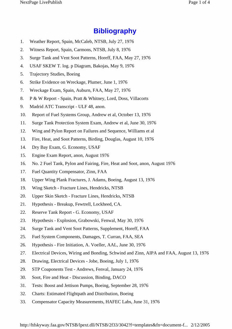
Bibliography1. Weather Report, Spain, McCaleb, NTSB, July 27, 1976
2. Witness Report, Spain, Carmons, NTSB, July 8, 1976
3. Surge Tank and Vent Soot Patterns, Horeff, FAA, May 27, 1976
4. USAF SKEW T. log. p Diagram, Bakojas, May 9, 1976
5. Trajectory Studies, Boeing
6. Strike Evidence on Wreckage, Plumer, June 1, 1976
7. Wreckage Exam, Spain, Auburn, FAA, May 27, 1976
8. P & W Report - Spain, Pratt & Whitney, Lord, Doss, Villacorts
9. Madrid ATC Transcript - ULF 48, anon.
10. Report of Fuel Systems Group, Andrew et al, October 13, 1976
11. Surge Tank Protection System Exam, Andrew et al, June 30, 1976
12. Wing and Pylon Report on Failures and Sequence, Williams et al
13. Fire, Heat, and Soot Patterns, Birding, Douglas, August 10, 1976
14. Dry Bay Exam, G. Economy, USAF
15. Engine Exam Report, anon, August 1976
16. No. 2 Fuel Tank, Pylon and Fairing, Fire, Heat and Soot, anon, August 1976
17. Fuel Quantity Compensator, Zinn, FAA
18. Upper Wing Plank Fractures, J. Adams, Boeing, August 13, 1976
19. Wing Sketch - Fracture Lines, Hendricks, NTSB
20. Upper Skin Sketch - Fracture Lines, Hendricks, NTSB
21. Hypothesis - Breakup, Fewtrell, Lockheed, CA.
22. Reserve Tank Report - G. Economy, USAF
23. Hypothesis - Explosion, Grabowski, Fenwal, May 30, 1976
24. Surge Tank and Vent Soot Patterns, Supplement, Horeff, FAA
25. Fuel System Components, Damages, T. Curran, FAA, SEA
26. Hypothesis - Fire Initiation, A. Voeller, AAL, June 30, 1976
27. Electrical Devices, Wiring and Bonding, Schwind and Zinn, AIPA and FAA, August 13, 1976
28. Drawing, Electrical Devices - Jobe, Boeing, July 1, 1976
29. STP Coaponents Test - Andrews, Fenval, January 24, 1976
30. Soot, Fire and Heat - Discussion, Binding, DACO
31. Tests: Boost and Jettison Pumps, Boeing, September 28, 1976
32. Charts: Estimated Flightpath and Distribution, Boeing
33. Compensator Capacity Measurements, HAFEC Labs, June 31, 1976
Page 1 of 4NextPage LivePublish
2/12/2005http://hfskyway.faa.gov/NTSB/lpext.dll/NTSB/2f33/3042?f=templates&fn=document-f...

34. VOR Antenna and Wingtip Lightning Damages and Drawings, Zinn, FAA
35. Wingtip Structure Damage
36. Hypothesis, Williams, Pan Am, June 2, 1976
37. UAL, 747, Incident Report and Lightning Data, June 7, 1976
38. Compensator, Physical Exam, Drawings, and Notes, NTSB, Honsywell, FAA, CE
39. Residue Analyses, September 8, 1976, Boeing, FBI
40. Fuel System Component Exams June 30, 1976, and September 28, 1976
41. Fire and Explosion Study, Grabowski, Fenval, November 12, 1976
42. Compensstor Breakdown Tests, 6/76, Plumer, CI
43. Static Discharge Reports, B-747, Lavers, Air Canada, June 4, 1976
44. Wing Structure Factual Report, November, 30, 1976, Williams, Pan Am
45. Fuel Line Collapse Test, October 28, 1976, Boeing
46. Wichita Modification Plan, 747, Document No. D3-8168-50, Boeing, August 28, 1975
47. Upper Wing Skin Exam, NTSB, Marx, June 30, 1976
48. Damage Report, September 20, 1976, Battelle
49. Summary and Discussion, Fewtrell, October 19, 1976, Lockheed California
50. Wing Skin Group Report, August 1976, J. Houck, NTSB
51. Overpressure for Skin Loss, Table, Boeing, March 15, 1977
52. Damage Report, Fuel Overpressure Incident, Boeing
53. Mid Spar Fuse Pins, Boeing
54. Flame Propagation Rates, Boeing
55. Electrical Transients, CVR Analysis, July 19, 1976, Turner, NTSB
56. P & W Letter, re engine Vibrations, dated May 20, 1971
57. CVR Factual Report, May 21, 1976, Turner, NTSB
58. Sparking Tests, Fuel Vent Couplings, December 2, 1976, Plumer, GE
59. Hypothesis and Recommendations, March 31, 1977, Plumer, GE
60. Fuel System Drawing and Notes, Plumer, GE
61. CVR Transient Comments, August 17, 1976, Plumer, GE
62. Boeing Conclusions, Explosion etc. and Photos, November 2, 1976, Boeing
63. Tank Access Doors, Wing Plank Sample, Report, February 11, 1977, Boeing
64. Load Transfer — Spars and Stringers to Skin, November 1976, Boeing
65. Stringer Loads, November 1976, Boeing, Pottinger
66. Lower Skin Marks and Nacelle Punctures Report, December 20, 1976, Boeing
67. IIAF VOR Antenna Tests, February 11, 1977, Boeing
68. Accident Report, February 1977, Lanoway, NTSB
Page 2 of 4NextPage LivePublish
2/12/2005http://hfskyway.faa.gov/NTSB/lpext.dll/NTSB/2f33/3042?f=templates&fn=document-f...

69. Damage Report, Final, January 31, 1977, Battelle
70. Additional Comments, May 1977, Fewtrell, Lockheed California
71. FDR Report, Carroll, December 7, 1976, NTSB
72. Lightning and Explosion Examination, Hacker, NASA (ret), February 3, 1977
73. Alert Service Bulletin, P & W, No. 3108, March 1972
74. Telegram: All JT9D Operators, P & W, January and February 1971
75. Wing/Engine Vibration, B-747, American Airlines, August 27, 1976
76. Fuel System Analysis, Failure Analysis, Letter, December 3, 1976, Boeing
77. Fuel System — Ignition Protection, December 9, 1968, Boeing
78. AD, Boeing, June 20, 1977
79. KC-135 Accident Report, June 3, 1971, Tarrejon, Spain, USAF
80. Structural Analysis, January 27, 1977, Wade, Lockheed Georgia
81. Electrical Inspection Report, September 30, 1976, Boeing
82. Wing Failure Analysis, Report to FAA from Boeing, October 5, 1976
83. KC-135Q Accident Summary, USAF
84. Wing Drawing of Fire Heat Soot, Bob Ray, Lockheed California, November 11, 1976
85. Wing Fire Study and Analysis, Binding, DACO, November 24, 1976
86. Strike Evidence on CVR, Plumer, GE, December 1976
87. Compensator Microscopic Exam, Plumer, GE, November 1976
88. Wiggins Coupling Arcing Exam, Plumer, GE March 1977
89. Chart, CVR with Flightpath, Bruggink
90. Lightning Exam, Wiggins Coupling, Magnetic Fields, Mangold, USAF, February 7, 1977
91. Autopilot Hardover and Flammability of JP-4, Boeing, July 8, 1977
92. Eardovers and Oscillatory Control Loads, D6-30870-3, B-747-100, Boeing
93. Structural Design Loads, D6-13248-3, B-747, Boeing
94. Tube Collapse Test Photos, August 1977, Battelle
95. Dynamic Loads Group Report, NASA, Houbolt, April 1977
96. CVR Update, May 1977 Turner, NTSB
97. Special Studies, CVR, Turner, May 1977, NTSB
98. Metallurgist Analysis Report, April 27, 1977, Houck, NTSB
99. Lightning Protection B-747, Document D6-13487, Boeing
100. STP Certification, FAA/Boeing, November 25, 1969
101. Calculated Pressure and Strain Energy, March 15, 1977, Boeing
102. Structural Design Loads, B-747, Document No. D6-30870-1, Boeing
103. Dynamic Vertical Gust Analysis, B-747-100 Document No. D6-13318, Boeing
Page 3 of 4NextPage LivePublish
2/12/2005http://hfskyway.faa.gov/NTSB/lpext.dll/NTSB/2f33/3042?f=templates&fn=document-f...

104. Dynamic Gust Mission Analysis, 747-100/200, D6-30552, Boeing
105. CVR Analysis Report, Turner, July 19, 1976, NTSB
106. Service Bulletins, B-747, Boeing No. 747-28-2047, 747-24-2058, July 11, 1975, November 18, 1988
107. Engine Induced Airframe Excitation, Boeing, September 8, 1976
108. Distribution Chart, Boeing
Page 4 of 4NextPage LivePublish
2/12/2005http://hfskyway.faa.gov/NTSB/lpext.dll/NTSB/2f33/3042?f=templates&fn=document-f...

Persons And Organizations Involved In The Investigation
In addition to NTSB personnel the following people were involved in the investigation and examination of the left wing:
Page 1 of 1NextPage LivePublish
2/12/2005http://hfskyway.faa.gov/NTSB/lpext.dll/NTSB/2f33/30af?f=templates&fn=document-f...

Federal Aviation Administration
Robert J. Auburn, Chief, Propulsion Branch, AFS-140
Iven D. Connally, B-747 Structures Project Engineer, ANW-212
Thomas F. Curran, Chief, Propulsion Section, ANW-214
Thomas G. Horeff, Propulsion Safety, ARD-520
Francis R. Schmidt, Aerospace Engineer, AFS-120
Samuel V. Zinn, Aerospace Engineer, ANA-420
Page 1 of 1NextPage LivePublish
2/12/2005http://hfskyway.faa.gov/NTSB/lpext.dll/NTSB/2f33/30af/30b1?f=templates&fn=docu...

Trans World Airlines
Joseph N. Barrack, Mgr., Aircraft Structures Engineering
Kenneth S. Craycraft, Senior Project Engineer
Page 1 of 1NextPage LivePublish
2/12/2005http://hfskyway.faa.gov/NTSB/lpext.dll/NTSB/2f33/30af/30b8?f=templates&fn=docu...

Prev Doc | Next Doc | Reference | Sync TOC | Prefs
Page 1 of 1Nav Bar
2/12/2005http://hfskyway.faa.gov/NTSB/lpext.dll/NTSB/1?f=templates&fn=docnav-ntsb.htm&2....

American Airlines
Albinus P. Voeller, Project Engineer
Page 1 of 1NextPage LivePublish
2/12/2005http://hfskyway.faa.gov/NTSB/lpext.dll/NTSB/2f33/30af/30bd?f=templates&fn=docu...

United Air Lines
Robert DeRosa, Aircraft Engineer
Page 1 of 1NextPage LivePublish
2/12/2005http://hfskyway.faa.gov/NTSB/lpext.dll/NTSB/2f33/30af/30bf?f=templates&fn=docum...

Douglas Aircraft Company McDonnell Douglas Corp. —
Alec T. Binding, Senior Staff Engineer
Page 1 of 1NextPage LivePublish
2/12/2005http://hfskyway.faa.gov/NTSB/lpext.dll/NTSB/2f33/30af/30c1?f=templates&fn=docu...

Fenwall Incorporated
William G. Andrew, Jr., Vice President-Engineering
George J. Grabowski, Vice President, Protection Systems.
Page 1 of 1NextPage LivePublish
2/12/2005http://hfskyway.faa.gov/NTSB/lpext.dll/NTSB/2f33/30af/30c3?f=templates&fn=docu...

Minneapolis Honeywell — Avionics Division
William R. Dougherty, Principal Development Engineer
Page 1 of 1NextPage LivePublish
2/12/2005http://hfskyway.faa.gov/NTSB/lpext.dll/NTSB/2f33/30af/30c6?f=templates&fn=docu...

Boeing Commercial Airplane Company
James H. Adams, Specialist Engineer — Metals
Thomas H. Barns, Senior Specialist, 747 Propulsion Technology
Elwood C. Brown, Group Supervisor, Systems Technology — Electrical
R. Earl Jobe, Group Supervisor, 747 Systems Technology — Avionics
Kenneth A. Martin, Chief, 747 Stress Unit
J. Cc_rie McMillan, Chief, Materials Technology — Chemical
Ivan L. Oliver, Senior Specialist, 747 Propulsion Technology
Robert G. Orr, Lead Engineer, 747 Propulsion Systems
Earold R. Piper, Coordinator, Air Safety Investigation
Edward Pottinger, Group Engineer, 747 Wing and Landing Gear System
Kichard C. Steele, Lead Engineer, 747 Wing Group
Page 1 of 1NextPage LivePublish
2/12/2005http://hfskyway.faa.gov/NTSB/lpext.dll/NTSB/2f33/30af/30c8?f=templates&fn=docu...

Lockheed—California Co.
H. E. Fewtrell, Staff Engineer, Structures and Materials
Robert F. Ray, Production Design Administrator
Page 1 of 1NextPage LivePublish
2/12/2005http://hfskyway.faa.gov/NTSB/lpext.dll/NTSB/2f33/30af/30d4?f=templates&fn=docu...
Lockheed—Georgia Co.
Henry H. Wade, Group Engineer, C-141 Structural Analysis
A. P. Shewmaker, Department Engineer, C-5 Structural Analysis
Page 1 of 1NextPage LivePublish
2/12/2005http://hfskyway.faa.gov/NTSB/lpext.dll/NTSB/2f33/30af/30d7?f=templates&fn=docu...

Air Line Pilots Association
John Burn, Captain, Pan American World Airways
Joseph M. Schwind, Deputy Mgr. — Engineering, Engineering and Air Safety Dept.
Page 1 of 1NextPage LivePublish
2/12/2005http://hfskyway.faa.gov/NTSB/lpext.dll/NTSB/2f33/30af/30da?f=templates&fn=docu...

United States Air Force
G.S. Economy, Aerospace Engineer, Air Force Inspection and Safety Center
Vernon L. Mangold, Chief, Electromagnetic Hazards Test Facility, Wright-Patterson, AFB
Charles L. Pocock, Lt. Col., Action Officer C-141, C-5, Air Force Inspection and Safety Center
Page 1 of 1NextPage LivePublish
2/12/2005http://hfskyway.faa.gov/NTSB/lpext.dll/NTSB/2f33/30af/30dd?f=templates&fn=docu...
Imperial Iranian Air Force
A. Hosseini, Captain
Page 1 of 1NextPage LivePublish
2/12/2005http://hfskyway.faa.gov/NTSB/lpext.dll/NTSB/2f33/30af/30e1?f=templates&fn=docu...

Battelle
David Broek, Ph.D., Project Leader
Samuel H. Smith, Frincipal Research Scientist
Page 1 of 1NextPage LivePublish
2/12/2005http://hfskyway.faa.gov/NTSB/lpext.dll/NTSB/2f33/30af/30e3?f=templates&fn=docu...

Pratt & Whitney Aircraft Group of United Technologies Corp.
Ramon G. Doss, Product Support Technical Liaison
Matson M. Lord, Chief, Product Support Technical Liaison
Page 1 of 1NextPage LivePublish
2/12/2005http://hfskyway.faa.gov/NTSB/lpext.dll/NTSB/2f33/30af/30e6?f=templates&fn=docu...

National Aeronautics and Space Administration
John Houbolt, Ph.D., Chief Aeronautical Engineer
J.B. Esgar, Chief, Airbreathing Engines Division
David P. Fleming, Ph.D., Head, Shaft and Rotor Dynamics Section
Wilbur H. Reed, Head, Aeroelasticity Branch, Structures and Dynamics Division
Richard S. Bray, Research Scientist, Flight Systems Dynamics
Paul Hacker, (retired) Consultant.
Page 1 of 1NextPage LivePublish
2/12/2005http://hfskyway.faa.gov/NTSB/lpext.dll/NTSB/2f33/30af/30e9?f=templates&fn=docu...

General Electric Corp.
J. Anderson, Plumer, Manager, Environmental Electromagnetics Unit.
Page 1 of 1NextPage LivePublish
2/12/2005http://hfskyway.faa.gov/NTSB/lpext.dll/NTSB/2f33/30af/30f0?f=templates&fn=docum...

1All times herein are Greemrich mean time, unless otherwise indicated.
U.S. Army
Benjamin E. Cummings, Ph.D., Chief, Vulnerability, B.R.L.
Page 1 of 1NextPage LivePublish
2/12/2005http://hfskyway.faa.gov/NTSB/lpext.dll/NTSB/2f33/30af/30f2?f=templates&fn=docum...