06 lifting & rigging hardware - shipserv · rigging screws in accordance with australian...
TRANSCRIPT
Lifti
ng &
Rig
ging
Hard
ware
06 Lifting & Rigging Hardware.qxd 15/2/12 5:39 PM Page 1

120
Lifting & Rigging Hardware
RIGGING SCREWS & TURNBUCKLESTO AS 2319
Rigging ScrewsRigging screws are used to provide a means for lengthadjustment and for tensioning. They are also used with guys formasts, towers, other structures and engineering applications.Rigging screws generally have elongated eyes or clevis endfittings for connection to shackles, wire rope assemblies, pad eyesand the like. A central cross-hole is provided at the inner end ofthe thread and at each end of the body, which permits visualobservation of the maximum permitted extended position of theend fitting. Rigging screw bodies are formed from tubular sectionsof steel and can have an almost infinite size range and scope forlength adjustment. Size and adjustment of rigging screws islimited by the available end fittings. Additionally, rigging screwshave the innate facility for continuing lubrication as the enclosedsection of the body provides a suitable reservoir for grease orother lubrication. Hence, they have an advantage in relativecorrosive applications such as ships rigging and permanentoutdoor guys.
TurnbucklesTurnbuckles have the same applications as rigging screws, but have a generally smaller size range and shorter adjustment. The main benefit of a turnbuckle is that it may have a greaterability to be tightened under load. Also, there may be a widerscope for providing means for locking while in service.
Rigging Screw GradeRigging Screws and Turnbuckles in accordance with AustralianStandards are available in various grades. The standard Noblesgrade of supply is Grade P. Other grades (S and L) are availableand some stocks may be held in specific sizes.
Grade LGrade L is the original grade of supply for rigging screws. It isfrom this grade that most of the dimensions of standard riggingscrew components are derived. The load ratings of Grade Lrigging screws equate to slightly better than mild steel. AlthoughGrade L rigging screws are still favoured in the commercial fishingindustry it is now generally an obsolete grade for rigging screws.The use of Grade L rigging screws is now generally limited to studended rigging screws which must be soft enough to swage andstub ended rigging screws where weldability is required.
Grade PGrade P is obtained using Nobles carefully developed heattreatment process. This grade is intended to reduce the size of rigging screws or turnbuckles required for a given load orapplication. The many benefits of Grade P include high strengthand appropriate size and fitment with modern wire rope andaccessories. Nobles were at the forefront of the development of this grade and have developed practices to generate theadditional strength required whilst retaining suitable materialductility for lifting applications.
Rigging Screw Grades
Stre
ngth
Grade
L
P
S
Grade SGrade S is a grade of rigging screw that is higher in capacity thanGrade P and normally requires the use of alloy steels in manufactureto generate material strengths akin to those of Grade 8.8 bolts.Some components are made and stocked in this grade but it isusually reserved for special purpose applications where Grade P is not viable.
Other GradesNobles have successfully manufactured rigging screws in specialgrades such as stainless steels, bronzes etc. These rigging screwmaterials differ widely in properties and our engineering expertise is used in assigning appropriate load ratings and sizing ofcomponentry.
Lifting & RiggingHardware
06 Lifting & Rigging Hardware.qxd 15/2/12 5:39 PM Page 2

121
RIGGING SCREWS & TURNBUCKLESTO AS 2319
Rigging Screw Barrel SizesApart from standard lengths (B) rigging screw barrels can also bemade in custom lengths to specific order requirements.
If locknuts are specified these will reduce the available thread onend fittings and increase overall minimum length. If locknuts arerequired please specify at time of order.
Rigging Screw SizesRigging screws can be made in almost any practical size orconfiguration. The standard end fittings are either elongated eyesor forged jaws.
Standard body types are either turnbuckles or rigging screws up to M33 and rigging screws only from M39 and above.
Nominal Grade L Grade P Grade SSizeM10 0.3 0.6 0.8M12 0.5 1 1.2M16 0.75 1.6 2M20 1.25 2.5 3.2M24 2.5 4 5M27 3 5 6.3M30 4 6.3 8M33 5 8 10M39 6 10 12M42 7.5 12 16M48 10 16 20M56 15 20/25* 28/32*M64 20 28/32* 36/40*M70 - 36 -M76 - 42 -M90 - 60 -M100 - 75 -
* AS 2319:1984 CAPACITY STILL NOBLES STD SUPPLY
NON PREFFERED GRADE OR SIZE, MAY NOT BE READILY AVAILABLE
WARNING• Swapping of end fittings between rigging screws and
turnbuckles is not recommended. If end fittings must be swapped consult Nobles for advice.
• Exceeding the WLL could result in faillure.
Load RatingRigging screws in accordance with Australian Standards have afactor of safety of 6:1. This relatively high factor is an importantsafety feature. The safety factor helps to counter possibleproblems from shock, vibration, fatigue, wear, damage andcorrosion. It is important that the safety factor be maintained.
When using a rigging screw always check the working load limit(WLL) stamped on the body. If the rigging screw is a customitem, and the WLL has been altered accordingly, then this will bereflected on the body stamping.
Locking of ThreadsWhere rigging screws or turnbuckles are to be used in apermanently adjusted position and where a guy is subjected toshock vibration or rope spin it is necessary to prevent the screwsfrom unwinding. Typical methods of locking threads includelocknuts, locking plates and wire.
LocknutsLocknuts are available for each size of rigging screw offered asstandard. Nobles rigging screw threads are toleranced such thatany standard nut of the correct thread series may be used as alock nut.
WARNING• Locknuts may not provide sufficient protection against unwinding
where torques are high• Overtightening Locknuts may cause threads to become
overloaded risking accidental failure.• Never cross drill the load bearing portion of an end fitting thread
to enable locking• Never weld rigging screws or turnbuckles to lock threads• Lock plates are the most secure locking method and should be
used where rope torque is significant.
WLL TONNES
(a) Pair of plates
Lock wire
(b) Wire
(c) Lock nut
Lock nut
WARNING• Regular inspection is required for all rigging screws (including
stainless steel ones) to reduce the risk of failure through corrosion
• Failure though corrosion may occur by erosion of the thread within the body being invisible except under close inspection
• Where rigging screw bodies are situated such that water or chemicals can collect within the barrel then the barrel should: be regularly maintained, charged with grease, have it’s holes plugged, have drain holes added or a combination of these. Nobles can add drain holes on request.
• Care should be taken that rigging screws fitted in line with dissimilar metals are not at risk from accelerated corrosion
Lifti
ng &
Rig
ging
Hard
ware
Lifting & Rigging Hardware
06 Lifting & Rigging Hardware.qxd 15/2/12 5:39 PM Page 3
122
RIGGING SCREWS & TURNBUCKLESTO AS 2319
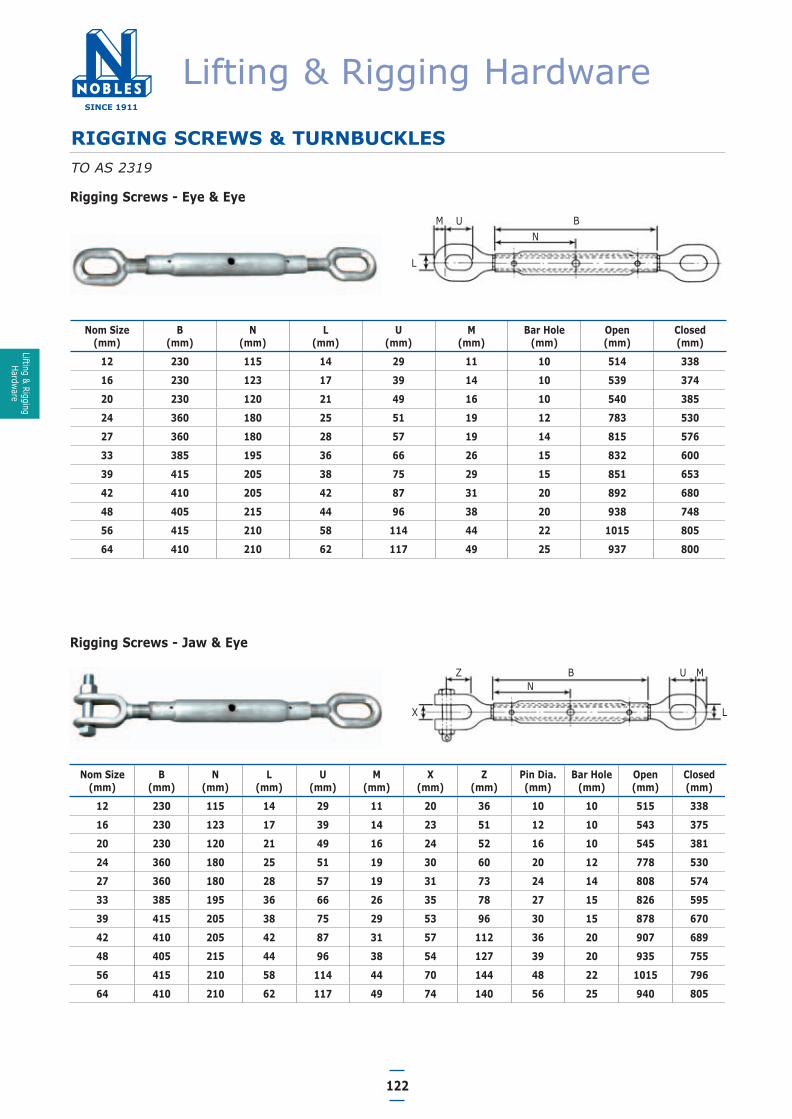
Rigging Screws - Eye & Eye
Nom Size(mm)
B(mm)
N(mm)
L(mm)
U(mm)
M(mm)
Bar Hole(mm)
Open(mm)
Closed(mm)
12 230 115 14 29 11 10 514 338
16 230 123 17 39 14 10 539 374
20 230 120 21 49 16 10 540 385
24 360 180 25 51 19 12 783 530
27 360 180 28 57 19 14 815 576
33 385 195 36 66 26 15 832 600
39 415 205 38 75 29 15 851 653
42 410 205 42 87 31 20 892 680
48 405 215 44 96 38 20 938 748
56 415 210 58 114 44 22 1015 805
64 410 210 62 117 49 25 937 800
Rigging Screws - Jaw & Eye
Nom Size(mm)
B(mm)
N(mm)
L(mm)
U(mm)
M(mm)
X(mm)
Z(mm)
Pin Dia.(mm)
Bar Hole(mm)
Open(mm)
Closed(mm)
12 230 115 14 29 11 20 36 10 10 515 338
16 230 123 17 39 14 23 51 12 10 543 375
20 230 120 21 49 16 24 52 16 10 545 381
24 360 180 25 51 19 30 60 20 12 778 530
27 360 180 28 57 19 31 73 24 14 808 574
33 385 195 36 66 26 35 78 27 15 826 595
39 415 205 38 75 29 53 96 30 15 878 670
42 410 205 42 87 31 57 112 36 20 907 689
48 405 215 44 96 38 54 127 39 20 935 755
56 415 210 58 114 44 70 144 48 22 1015 796
64 410 210 62 117 49 74 140 56 25 940 805
NB
L
UM
NB
L
U M
X
Z
Lifting & Rigging Hardware
Lifting & RiggingHardware
06 Lifting & Rigging Hardware.qxd 15/2/12 5:39 PM Page 4

123
RIGGING SCREWS & TURNBUCKLESTO AS 2319
Rigging Screws - Jaw & Jaw
Nom Size(mm)
B(mm)
N(mm)
X(mm)
Z(mm)
Pin Dia.(mm)
Bar Hole(mm)
Open(mm)
Closed(mm)
12 230 115 20 36 10 10 516 335
16 230 123 23 51 12 10 544 380
20 230 120 24 52 16 10 550 384
24 360 180 30 60 20 12 761 521
27 360 180 31 73 24 14 788 562
33 385 195 35 78 27 15 813 590
39 415 205 53 96 30 15 906 682
42 410 205 57 112 36 20 925 702
48 405 212 54 127 39 20 944 755
56 415 210 70 144 48 22 1005 800
64 410 210 74 140 56 25 940 800
Turnbuckles Eye & Eye
Nom Size A(mm)
B(mm)
N(mm)
L(mm)
U(mm)
M(mm)
Bar Hole(mm)
Open(mm)
Closed(mm)
12 190 115 14 29 11 10 474 329
16 202 123 17 39 14 10 520 368
20 218 120 21 49 16 10 528 383
24 227 180 25 51 19 12 573 418
27 257 180 28 57 19 14 645 491
33 275 195 36 66 26 15 651 481
NB
L
UM
NB
X
Z
Lifti
ng &
Rig
ging
Hard
ware
Lifting & Rigging Hardware
06 Lifting & Rigging Hardware.qxd 15/2/12 5:39 PM Page 5

124
RIGGING SCREWS & TURNBUCKLES TO AS 2319
Turnbuckles Jaw & Eye
Nom Size A(mm)
B(mm)
N(mm)
L(mm)
U(mm)
M(mm)
X(mm)
Z(mm)
P(mm)
Bar Hole(mm)
Open(mm)
Closed(mm)
12 190 115 14 29 11 20 36 10 10 479 337
16 202 123 17 39 14 23 51 12 10 527 377
20 218 120 21 49 16 24 52 16 10 527 383
24 227 180 25 51 19 30 60 20 12 557 405
27 257 180 28 57 19 31 73 24 14 631 468
33 275 195 36 66 26 35 78 27 15 659 497
Turnbuckles Jaw & Jaw
Nom Size A(mm)
B(mm)
N(mm)
L(mm)
U(mm)
M(mm)
X(mm)
Z(mm)
P(mm)
Bar Hole(mm)
Open(mm)
Closed(mm)
12 190 115 14 29 11 20 36 10 10 479 334
16 202 123 17 39 14 23 51 12 10 525 380
20 218 120 21 49 16 24 52 16 10 530 384
24 227 180 25 51 19 30 60 20 12 545 397
27 257 180 28 57 19 31 73 24 14 626 464
33 275 195 36 66 26 35 78 27 15 663 497
NB
L
U M
X
Z
NB
X
Z
Lifting & Rigging Hardware
Lifting & RiggingHardware
06 Lifting & Rigging Hardware.qxd 15/2/12 5:39 PM Page 6

GeneralShackles are used in lifting static systems as removable links toconnect wire rope, chain and other fittings.
Shackle TypesGrade ‘M’ Large Dee and Grade ‘S’ Dee and Bow shackles are themost common types of rated lifting shackles that will beencountered in general industry.
Grade ‘S’ shackles are available with various pin configurationsbut the two main pin configurations are the ‘Safety Pin’ and the‘Screw Pin’.
Shackle LoadingThe Working Load Limit on a shackle varies according to the angleof the load.
The pre-use check for shackles should ensure that:1. The body of the shackle and pin are both compatible and are
of the same grade and material.
2. All markings are clearly legible.
3. The pin is the correct type for the shackle body.
4. The threads of the pin and the shackle body are in good orderand function correctly.
5. The body and pin are not damaged in any way and are freefrom distortion, nicks, gouges, cracks and excessive wear andcorrosion. (Recommended maximum wear allowance is 10%).
6. For ‘Safety pin’ shackles ensure that the nuts and split pinsare fitted and in good condition.
125
SHACKLESTO AS 2741
WARNING• Lifting equipment should be inspected before each use.
MarkingShackles designed and tested in accordance with AustralianStandard 2741 should be marked with the following• WLL.• Manufactures identification.• Grade of material.• Identification mark or batch number to cross reference the
shackle to the manufacturers test certificate.
1. With a screw pin shackle ensure that the pin is firmly screwedinto the shackle eye. The collar of the pin should be fullyseated on the shackle eye. The pin can be locked using asmall spanner or tommy bar. When using a safety pin shackleensure that the nut and split pin are attached and in goodcondition.
2. Ensure that the pin is of the correct length so that itpenetrates the full depth of the screwed eye and allows thecollar of the pin to bed on the surface of the shackle eye.
3. If the shackle pin does not seat correctly this indicates thatthe pin may be bent, the thread is not correct or compatibleor the pinholes are not aligned correctly. The shackle shouldnot be used under these circumstances.
4. Never replace a shackle pin with a bolt. The original shacklepin is specifically designed for the purpose and a bolt may notbe suited to the WLL of the shackle.
5. Safety pin shackles must never be used if the nut and splitpin are not in place.
6. Select the correct type of shackle for the intended use andapplication. Shackles should be fitted to the load in a mannerthat allows the shackle to be loaded along its centre line.Shackles should never be loaded in such a way thatinappropriate bending forces are induced.
7. To avoid eccentric loading of the shackle a loose spacer maybe used in either end of the shackle pin or a shackle with asmaller jaw width should be used. Do not reduce the widthbetween the shackle jaws by welding washers or spacers tothe inside face of the eyes or by closing the jaws, as this willhave an adverse affect on the mechanical properties of theshackle.
8. If a shackle is being used to secure the top block of a sheaveblock or "handy billy" arrangement it should be noted that thehoisting effort used to pull down on the load rope also needsto be allowed for when selecting the shackle WLL.
9. The WLL of shackles is affected at high temperaturestherefore the WLL’s should be reduced by 10% fortemperatures between 200 and 300˚C and by 25% fortemperatures between 300 and 400˚C. Grade S Shacklesshould not be used at all for temperatures above 400˚C.
10. Do not attempt to weld or apply heat to shackles.
Inspection Before Use
Care In Use
WARNING• Shackles should always be used in line with good lifting and
rigging practice and as per the manufacturers recommendations. • Incorrect shackle use could result in a dangerous situation that
could cause property damage, serious injury or death.• When using shackles in multi-leg slings, due consideration should
be given to the effect of the angle between the legs. As the included angle increases so to does the load in the sling leg and the shackle.
• Shackles should never be used on a sling with an included angle in excess of 120˚.
Check for wearinside shackle body
Check body for distortion
Check that splitpin is secure
Check for wear on shackle pin
Check that pin is matched to body, is the samegrade material and seats correctly in the shackle
45˚70% WLL
90˚50% WLL
In Line100% WLL
Lifting & Rigging Hardware
Lifti
ng &
Rig
ging
Hard
ware
06 Lifting & Rigging Hardware.qxd 15/2/12 5:39 PM Page 7

126
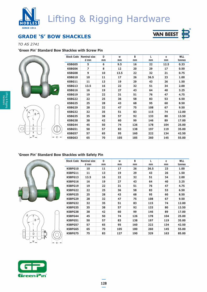
GRADE ‘S’ BOW SHACKLESTO AS 2741
Stock Code Nominal size D w B L e WLLd (mm) (mm) (mm) (mm) (mm) (mm) (tonnes)
KSBG05C 5 6 9.5 15 22 14 0.33KSBG06C 6 8 12 20 29 16 0.50KSBG08C 8 10 13.5 21 31 19 0.75KSBG10C 10 11 17 26 37 23 1.00KSBG11C 11 13 19 29 43 27 1.50KSBG13C 13 16 20 33 48 30 2.00KSBG16C 16 19 27 43 60 38 3.25KSBG19C 19 22 32 50 71 46 4.75KSBG22C 22 25 36 58 84 53 6.50KSBG25C 25 28 43 68 95 61 8.50KSBG29C 28 32 46 74 108 68 9.50KSBG32C 32 35 51 82 119 76 12.00
Stock Code Nominal size D w B L e WLLd (mm) (mm) (mm) (mm) (mm) (mm) (tonnes)
KSBFG13C 13 16 20 33 48 30 2.00KSBFG16C 16 19 27 43 60 38 3.25KSBFG19C 19 22 32 50 71 46 4.75KSBFG22C 22 25 36 58 84 53 6.50KSBFG25C 25 28 43 68 95 61 8.50KSBFG29C 28 32 46 74 108 68 9.50KSBFG32C 32 35 51 82 119 76 12.00
Nobles Grade ‘S’ Bow Shackles are recognisable by theirdistinctive blue pin. All Nobles Grade ‘S’ bow shackles are madestrictly in accordance with AS 2741 and are batch destructiontested at manufacture.
Nobles Grade ‘S’ bow shackles also have raised markings whichinclude the WLL, shackle size and batch number. This ensuresshackles can be easily identified during visual inspections well intotheir service life.
Remember the ‘Blue Pin’ is your guarantee of Nobles quality.
Nobles ‘Blue Pin’ Grade ‘S’ Bow Shackles with Screw Pin
Nobles ‘Blue Pin’ Grade ‘S’ Bow Shackles with Safety Pin
Lifting & Rigging Hardware
Lifting & RiggingHardware
06 Lifting & Rigging Hardware.qxd 15/2/12 5:39 PM Page 8
127
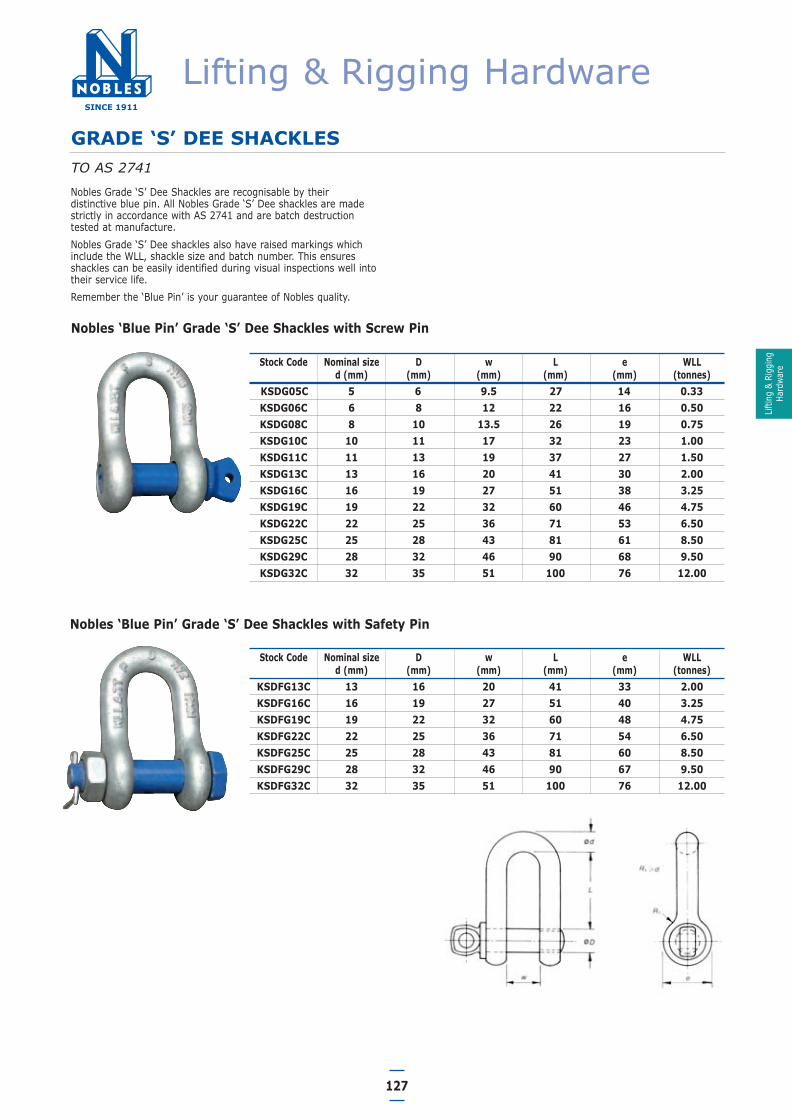
GRADE ‘S’ DEE SHACKLESTO AS 2741
Stock Code Nominal size D w L e WLLd (mm) (mm) (mm) (mm) (mm) (tonnes)
KSDG05C 5 6 9.5 27 14 0.33KSDG06C 6 8 12 22 16 0.50KSDG08C 8 10 13.5 26 19 0.75KSDG10C 10 11 17 32 23 1.00KSDG11C 11 13 19 37 27 1.50KSDG13C 13 16 20 41 30 2.00KSDG16C 16 19 27 51 38 3.25KSDG19C 19 22 32 60 46 4.75KSDG22C 22 25 36 71 53 6.50KSDG25C 25 28 43 81 61 8.50KSDG29C 28 32 46 90 68 9.50KSDG32C 32 35 51 100 76 12.00
Stock Code Nominal size D w L e WLLd (mm) (mm) (mm) (mm) (mm) (tonnes)
KSDFG13C 13 16 20 41 33 2.00KSDFG16C 16 19 27 51 40 3.25KSDFG19C 19 22 32 60 48 4.75KSDFG22C 22 25 36 71 54 6.50KSDFG25C 25 28 43 81 60 8.50KSDFG29C 28 32 46 90 67 9.50KSDFG32C 32 35 51 100 76 12.00
Nobles Grade ‘S’ Dee Shackles are recognisable by theirdistinctive blue pin. All Nobles Grade ‘S’ Dee shackles are madestrictly in accordance with AS 2741 and are batch destructiontested at manufacture.
Nobles Grade ‘S’ Dee shackles also have raised markings whichinclude the WLL, shackle size and batch number. This ensuresshackles can be easily identified during visual inspections well intotheir service life.
Remember the ‘Blue Pin’ is your guarantee of Nobles quality.
Nobles ‘Blue Pin’ Grade ‘S’ Dee Shackles with Screw Pin
Nobles ‘Blue Pin’ Grade ‘S’ Dee Shackles with Safety Pin
Lifting & Rigging Hardware
Lifti
ng &
Rig
ging
Hard
ware
06 Lifting & Rigging Hardware.qxd 15/2/12 5:39 PM Page 9
128
Stock Code Nominal size D w B L e WLLd mm mm mm mm mm mm tonnes
KSBG05 5 6 9.5 16 22 12.5 0.33KSBG06 7 8 12 20 29 17 0.50KSBG08 9 10 13.5 22 32 21 0.75KSBG10 10 11 17 26 36.5 23 1.00KSBG11 11 13 19 29 43 26 1.50KSBG13 13.5 16 22 32 51 34 2.00KSBG16 16 19 27 43 64 40 3.25KSBG19 19 22 31 51 76 47 4.75KSBG22 22 25 36 58 83 53 6.50KSBG25 25 28 43 68 95 60 8.50KSBG29 28 32 47 75 108 67 9.50KSBG32 32 35 51 83 115 74 12.00KSBG35 35 38 57 92 133 80 13.50KSBG38 38 42 60 99 146 89 17.00KSBG44 45 50 74 126 178 104 25.00KSBG51 50 57 83 138 197 119 35.00KSBG57 57 65 95 160 222 134 42.50KSBG63 65 70 105 185 260 145 55.00
Stock Code Nominal size D w B L e WLLd mm mm mm mm mm mm tonnes
KSBFG10 10 11 17 26 36.5 23 1.00KSBFG11 11 13 19 29 43 26 1.50KSBFG13 13.5 16 22 32 51 34 2.00KSBFG16 16 19 27 43 64 40 3.25KSBFG19 19 22 31 51 76 47 4.75KSBFG22 22 25 36 58 83 53 6.50KSBFG25 25 28 43 68 95 60 8.50KSBFG29 28 32 47 75 108 67 9.50KSBFG32 32 35 51 83 115 74 12.00KSBFG35 35 38 57 92 133 80 13.50KSBFG38 38 42 60 99 146 89 17.00KSBFG44 45 50 74 126 178 104 25.00KSBFG51 50 57 83 138 197 119 35.00KSBFG57 57 65 95 160 222 134 42.50KSBFG65 65 70 105 180 260 145 55.00KSBFG75 75 83 127 190 329 163 85.00
‘Green Pin’ Standard Bow Shackles with Screw Pin
‘Green Pin’ Standard Bow Shackles with Safety Pin
GRADE ‘S’ BOW SHACKLESTO AS 2741
B
e
d
w
L
D
B
e
d
w
L
D
Lifting & Rigging Hardware
Lifting & RiggingHardware
06 Lifting & Rigging Hardware.qxd 15/2/12 5:39 PM Page 10

129
Stock Code Nominal size D w L e WLLd (mm) (mm) (mm) (mm) (mm) (tonnes)
KSDG06 7 8 12 22 17 0.50KSDG08 9 10 13.5 26 21 0.75KSDG10 10 11 17 32 23 1.00KSDG11 11 13 19 37 26 1.50KSDG13 13.5 16 22 43 34 2.00KSDG16 16 19 27 51 40 3.25KSDG19 19 22 31 59 48 4.75KSDG22 22 25 36 73 53 6.50KSDG25 25 29 43 85 60 8.50KSDG29 28 32 47 90 67 9.50KSDG32 32 35 51 94 74 12.00KSDG35 35 38 57 115 80 13.50KSDG38 38 42 60 127 89 17.00KSDG44 45 50 74 149 104 25.00KSDG51 50 57 83 171 119 35.00KSDG57 57 65 95 190 134 42.50KSDG63 65 70 105 203 145 55.00
Stock Code Nominal size D w L e WLLd (mm) (mm) (mm) (mm) (mm) (tonnes)
KSDFG13 13.5 16 22 43 34 2.00KSDFG16 16 19 27 51 40 3.25KSDFG19 19 22 31 59 48 4.75KSDFG22 22 25 36 73 53 6.50KSDFG25 25 28 43 85 60 8.50KSDFG29 28 32 47 90 67 9.50KSDFG32 32 35 51 94 74 12.00KSDFG35 35 38 57 115 80 13.50KSDFG38 38 42 60 127 89 17.00KSDFG44 45 50 74 149 104 25.00KSDFG51 50 57 83 171 119 35.00KSDFG57 57 65 95 190 134 42.50KSDFG63 65 70 105 203 145 55.00KSDFG75 75 83 127 229 163 85.00
Van Beest ‘Green Pin’ Standard Dee Shackles with Screw Pin
Van Beest ‘Green Pin’ Standard Dee Shackles with Safety Pin
GRADE ‘S’ DEE SHACKLESTO AS 2741
Lifting & Rigging Hardware
Lifti
ng &
Rig
ging
Hard
ware
06 Lifting & Rigging Hardware.qxd 15/2/12 5:39 PM Page 11

130
GRADE ‘S’ BOW SHACKLES
Stock Code Nominal size w B L D e WLLd mm mm mm mm mm mm tonnes
KSBFG95 95 144 238 381 95 215 120KSBFG105 105 165 275 400 108 245 150
- 120 175 290 500 130 288 200- 130 200 305 540 140 308 250- 140 200 305 600 150 335 300- 170 225 325 650 175 387 400- 180 250 350 700 185 410 500- 200 275 375 700 205 458 600- 210 300 400 700 215 468 700- 210 300 400 700 220 478 800- 220 320 420 700 230 500 900- 240 340 420 700 240 530 1,000- 260 360 450 700 270 600 1,250- 280 360 450 700 290 640 1,500
Stock Code Nominal size D w B L e WLLd mm mm mm mm mm mm tonnes
KSWBG055 60 57 95 160 250 115 55KSWBG075 70 70 105 186 290 140 75KSWBG125 85 80 130 220 365 155 125KSWBG150 94 95 140 250 390 180 150KSWBG200 110 105 150 276 480 200 200
- 126 120 170 300 540 228 250- 135 134 185 350 600 245 300
KSWBG400 160 160 220 370 575 295 400- 170 180 250 450 680 330 500- 190 200 275 490 740 350 600- 200 215 300 540 750 392 700- 218 230 325 554 850 420 800- 242 255 350 584 850 466 900- 260 270 380 614 855 490 1,000- 285 300 430 650 930 510 1,250- 295 320 460 680 950 550 1,500
‘Green Pin’ Heavy Duty Bow Shackles with Safety Pin
‘Green Pin’ Sling Shackle with Safety Pin
d
D
ew
L
B
B
e
d
w
L
D
1500 Tonne Sling Shackle
Lifting & Rigging Hardware
Lifting & RiggingHardware
06 Lifting & Rigging Hardware.qxd 15/2/12 5:39 PM Page 12

Grade 8 shackles with quenched and tempered pin and bow. Meets requirements of US Fed Spec RR-C-271 Type IVA Class 3, Grade BMBL = 5 x WLL .
131
SUPER SHACKLES
Stock Code Nom. size D w B L e WLLd mm mm mm mm mm mm tonnes
KTBFG13 13.5 16 22 32 51 34 3.3KTBFG16 16 19 27 43 64 40 5.0KTBFG19 19 22 31 51 76 47 7.0KTBFG22 22 25 36 58 83 53 9.5KTBFG25 25 28 43 68 95 60 12.5KTBFG29 28 32 47 75 108 67 15.0KTBFG32 32 35 51 83 115 74 18.0KTBFG35 35 38 57 92 133 80 21.0KTBFG38 38 42 60 99 146 89 30.0KTBFG44 45 50 74 126 178 104 40.0KTBFG57 57 57 83 138 197 133 55.0KTBFG70 70 70 105 180 260 159 85.0KTBFG83 83 83 127 190 329 171 120.0
B
e
d
w
L
D
Extra wide mouth shackle, suitable for lifting.Grade 8 shackles with quenched and tempered pin and bow.MBL = 6 x WLL
WIDE MOUTH SHACKLES
Stock Code Nom. size D w B L e WLLd mm mm mm mm mm mm tonnes
KTBWM475 22 25 63 88 112 52 4.75KTBWM650 25 28 75 105 135 59 6.5KTBWM950 32 35 90 126 162 72 9.5KTBWM120 35 38 100 140 180 79 12KTBWM160 38 42 106 159 216 89 16KTBWM250 45 50 127 175 248 104 25KTBWM300 50 57 146 207 273 111 30KTBWM550 65 70 165 213 314 145 55KTBWM750 75 83 184 254 330 163 75
B
e
d
w
L
D
Lifting & Rigging Hardware
Lifti
ng &
Rig
ging
Hard
ware
06 Lifting & Rigging Hardware.qxd 15/2/12 5:39 PM Page 13
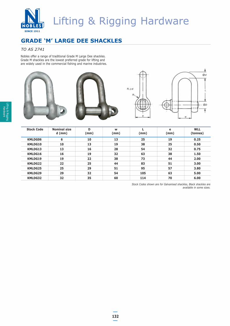
Stock Codes shown are for Galvanised shackles, Black shackles areavailable in some sizes.
132
Nobles offer a range of traditional Grade M Large Dee shackles.Grade M shackles are the lowest preferred grade for lifting andare widely used in the commercial fishing and marine industries.
Stock Code Nominal size D w L e WLL d (mm) (mm) (mm) (mm) (mm) (tonnes)
KMLDG06 6 10 13 25 19 0.25KMLDG10 10 13 19 38 25 0.50KMLDG13 13 16 28 54 32 0.75KMLDG16 16 19 32 63 38 1.50KMLDG19 19 22 38 73 44 2.00KMLDG22 22 25 44 83 51 3.00KMLDG25 25 29 51 95 57 3.80KMLDG29 29 32 54 105 63 5.00KMLDG32 32 35 60 114 70 6.00
GRADE ‘M’ LARGE DEE SHACKLES TO AS 2741
Lifting & RiggingHardware
Lifting & Rigging Hardware
06 Lifting & Rigging Hardware.qxd 15/2/12 5:39 PM Page 14

133
HOOKS
GeneralThere are numerous hook designs and configurations to suit manydifferent applications. It is important to select the right hook forthe job. Nobles sales staff can advise on the most suitable hooktypes for any given application.
Inspection Before UseThe pre-use check for hooks should cover the following:
1. The WLL should be clearly marked.2. The safety catch should be in place and functioning correctly.3. The hook should be checked for any distortion, cracking and
excessive wear or corrosion.NOTE: The wear on the bearing surface of the hook shouldnot exceed 8% of the nominal dimension.
4. Check that the opening of the hook is within themanufacturers parameters. If the hook is opened excessivelyit is a sign that it has been point loaded or overloaded.
5. Moving parts such as release cams should be checked for freemovement.
6. If the hook is a ball bearing swivel hook check that the hookis swivelling freely and that the bearing is not making anyunusual noises. Unusual noises are often a sign of bearingfatigue or bearing failure.
7. If the hook has a threaded machined shank ensure that thethread is in good order and that the nut is turning freely onthe thread.
MarkingAll hooks designed and tested in accordance with AustralianStandards shall include:• Manufacturer’s identification.• Quality grade.• SWL or WLL.• Identification marking or batch number to trace the hook to
the manufacturers test certificate.
Care In Use1. For hooks used in frequent load cycles or pulsating loads,
the hook and threads should periodically be inspected byMagnetic Particle or Dye Penetrant. (Note: Some disassemblymay be required.)
2. Never use a hook if its throat opening has been increased, orits tip has been bent more than 10 degrees out of plane fromthe hook body, or is in any other way distorted or bent. Note:A safety catch will not work properly on a hook with a bent orworn tip.
3. Never use a hook that is worn beyond a recommendedmaximum of 8%.
4. Remove from service any hook with a crack, nick, or gouge.Hooks with cracks, nicks, or gouges shall be repaired bycarefully grinding lengthwise, following the contour of thehook, provided that the reduced dimension is within the 8%wear limit.
5. Never repair, alter, rework, or reshape a hook by welding,heating, burning or bending.
6. Never side load, back load, or tip load a hook.7. Eye hooks, shank hooks and swivel hooks are designed to be
used with wire rope or chain. Efficiency of an assembly maybe reduced when used with synthetic material.
8. Always make sure the hook supports the load. The catch mustnever support the load.
9. When placing two sling legs in a hook, make sure the anglefrom the vertical to the outermost leg is not greater than 45 degrees, and the included angle between the legs does not exceed 90 degrees.
10. The WLL of a hook applies only when the load is correctlypositioned on the load line of the hook. If the hook iseccentrically loaded, or the load is applied other than on the load line, the WLL is greatly reduced.
11. Always use a swivel hook, or insert a swivel link between theload hook and the lifting rope, when the load has a tendencyto rotate when lifted.
12. Always check to ensure that the hook safety catch has closedcorrectly before allowing the load to be lifted.
WARNING• All hooks should be safety hooks i.e. have a safety catch.• Hooks without safety catches are not recommended.
WARNING• Loads may disengage from hooks if proper procedures are not
followed.• Falling loads may cause property damage, serious injury
or death.• Threads may corrode and/or strip and drop the load.• The hooks must always support the load. The load must never
be supported by the safety catch.• Never apply more force than the hook’s WLL.• Read and understand the manufacturers instructions before using
the hook.
Check for wear
Check for wear
Check forcracking or twisting
Checkoperation ofsafety catch
Check fordistortion
Side LoadIncorrect
Side LoadIncorrect
Correct CorrectIncorrect
Back LoadIncorrect
Tip LoadIncorrect
Lifti
ng &
Rig
ging
Hard
ware
Lifting & Rigging Hardware
06 Lifting & Rigging Hardware.qxd 15/2/12 5:39 PM Page 15
134
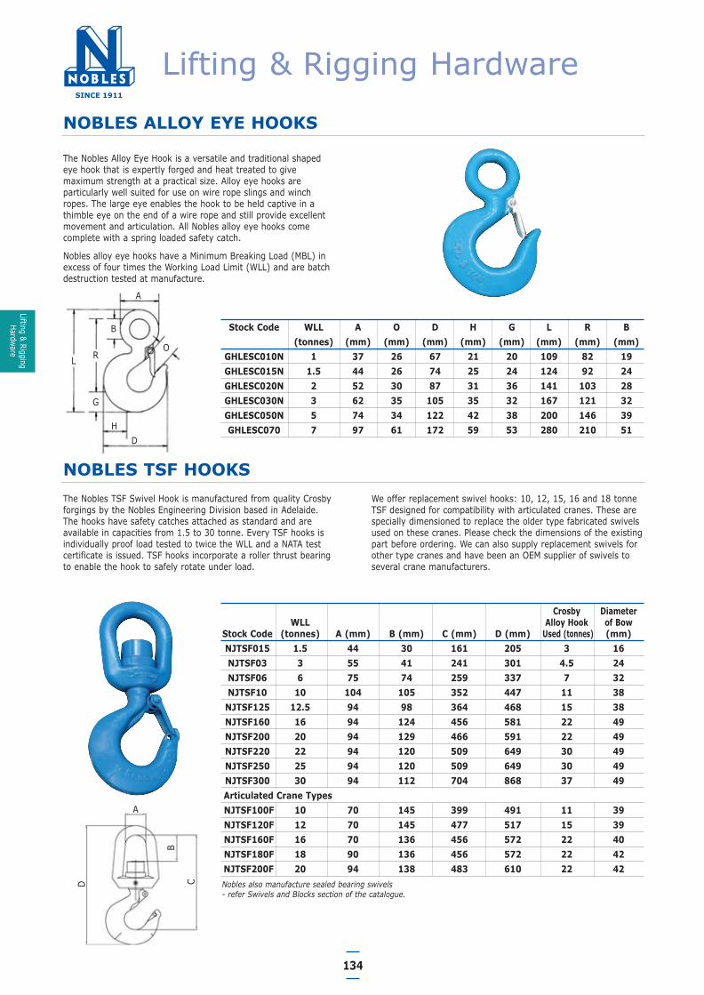
NOBLES ALLOY EYE HOOKS
The Nobles Alloy Eye Hook is a versatile and traditional shapedeye hook that is expertly forged and heat treated to givemaximum strength at a practical size. Alloy eye hooks areparticularly well suited for use on wire rope slings and winchropes. The large eye enables the hook to be held captive in athimble eye on the end of a wire rope and still provide excellentmovement and articulation. All Nobles alloy eye hooks comecomplete with a spring loaded safety catch.
Nobles alloy eye hooks have a Minimum Breaking Load (MBL) inexcess of four times the Working Load Limit (WLL) and are batchdestruction tested at manufacture.
Stock Code WLL A O D H G L R B(tonnes) (mm) (mm) (mm) (mm) (mm) (mm) (mm) (mm)
GHLESC010N 1 37 26 67 21 20 109 82 19GHLESC015N 1.5 44 26 74 25 24 124 92 24GHLESC020N 2 52 30 87 31 36 141 103 28GHLESC030N 3 62 35 105 35 32 167 121 32GHLESC050N 5 74 34 122 42 38 200 146 39GHLESC070 7 97 61 172 59 53 280 210 51
The Nobles TSF Swivel Hook is manufactured from quality Crosbyforgings by the Nobles Engineering Division based in Adelaide. The hooks have safety catches attached as standard and areavailable in capacities from 1.5 to 30 tonne. Every TSF hooks isindividually proof load tested to twice the WLL and a NATA testcertificate is issued. TSF hooks incorporate a roller thrust bearingto enable the hook to safely rotate under load.
Crosby DiameterWLL Alloy Hook of Bow
Stock Code (tonnes) A (mm) B (mm) C (mm) D (mm) Used (tonnes) (mm)NJTSF015 1.5 44 30 161 205 3 16NJTSF03 3 55 41 241 301 4.5 24NJTSF06 6 75 74 259 337 7 32NJTSF10 10 104 105 352 447 11 38
NJTSF125 12.5 94 98 364 468 15 38NJTSF160 16 94 124 456 581 22 49NJTSF200 20 94 129 466 591 22 49NJTSF220 22 94 120 509 649 30 49NJTSF250 25 94 120 509 649 30 49NJTSF300 30 94 112 704 868 37 49Articulated Crane TypesNJTSF100F 10 70 145 399 491 11 39NJTSF120F 12 70 145 477 517 15 39NJTSF160F 16 70 136 456 572 22 40NJTSF180F 18 90 136 456 572 22 42NJTSF200F 20 94 138 483 610 22 42
NOBLES TSF HOOKSWe offer replacement swivel hooks: 10, 12, 15, 16 and 18 tonneTSF designed for compatibility with articulated cranes. These arespecially dimensioned to replace the older type fabricated swivelsused on these cranes. Please check the dimensions of the existingpart before ordering. We can also supply replacement swivels forother type cranes and have been an OEM supplier of swivels toseveral crane manufacturers.
Nobles also manufacture sealed bearing swivels - refer Swivels and Blocks section of the catalogue.
A
D C
B
A
B
L R
G
HD
O
Lifting & RiggingHardware
Lifting & Rigging Hardware
06 Lifting & Rigging Hardware.qxd 15/2/12 5:39 PM Page 16

135
NOBLES SAFETY HANDLE HOOKS
Nobles Safety Handle Hooks are commonly used on the end of acrane pendant/stinger wire rope assembly. These hooks are usedextensively in onshore and offshore lifting applications.
The safety handle enables an operator to safely open and closethe hooks while keeping hands and gloves well clear of the closingmechanism. The safety handle also makes it easy to guide theopen hook onto the load ring or attachment point.
Stock Code WLL A B C F G H J O R S AA(tonnes) (mm) (mm) (mm) (mm) (mm) (mm) (mm) (mm) (mm) (mm) (mm)
GHSPSC010 1.25 51 20.8 31.8 31.8 18.5 20.6 23.6 23.6 116 9.65 38.1GHSPSC015 1.6 63.5 33.3 38.1 35.1 21.3 23.9 24.6 24.6 136 12.7 50.8GHSPSC020 2.5 76 38.1 44.5 38.1 25.4 29.5 26.9 26.9 155 16 50.8GHSPSC030 3.2 76 38.1 44.5 41.1 28.7 33.3 30.2 29.5 165 16 50.8GHSPSC045 5.4 89 41.7 50.8 51 36.6 41.4 38.1 35.8 191 19.1 63.5GHSPSC070 8.0 116 58.0 63.5 63.5 46 52.5 45.2 42.9 245 25.4 76.2GHSPSC110 11.5 127 64.5 70 76 57 67 51.0 56.5 289 28.7 101GHSPSC150 16.0 143 63.0 79 82.5 66 74.5 66.5 61 311 31.8 101GHSPSC220 22.0 180 95.5 104 108 76 89 86.5 81 424 38.1 127GHSPSC300 31.5 180 95.5 104 127 93 118 102 82.6 459 38.1 165
WARNING• This hook is a positioning device only and is not intended to
rotate under load.• For swivel hooks designed to rotate under load use the Nobles
TSF hook.
WARNING• This hook is a positioning device only and is not intended to
rotate under load.• For swivel hooks designed to rotate under load use the Nobles
TSF hook.
CROSBY ALLOY SWIVEL HOIST HOOKS
• Crosby Swivel Hoist Hooks are Forged, Quenched andTempered.
• Proper design, careful forging, and precision controlledquench and tempering gives maximum strength withoutexcessive weight and bulk.
• Crosby swivel hoist hooks come complete with a safety catch.
• Load rating codes are stamped on each hook.
• Hoist hooks incorporate markings forged into the productwhich address two (2) QUIC-CHECK® features:
1. Deformation Indicators - Two strategically placed marks,one just below the shank or eye and the other on the hooktip, which allows for a QUIC-CHECK® measurement todetermine if the throat opening has changed, thusindicating abuse or overload.
2. Angle Indicators - Indicates the maximum included anglewhich is allowed between two (2) sling legs in the hook.These indicators also provide the opportunity toapproximate other angles between two sling legs.
For Crosby alloy swivel hooks 1.5 - 30 tonne the proof load is 2 times Working Load Limit.
Crosby alloy swivel hooks have a 4:1 safety factor.
Stock Code Size WLL D L M N Weight ea.(mm) (tonnes) (mm) (mm) (mm) (mm) (kg)
CMHV16100SP 16 10.0 173 54 317 65 9.75CMHV20100SP 20 16.0 187 61 355 78 12.5
L
N
M
D
These hooks now supplied in Grade 100.
Lifti
ng &
Rig
ging
Hard
ware
Lifting & Rigging Hardware
06 Lifting & Rigging Hardware.qxd 15/2/12 5:39 PM Page 17

136
CROSBY SHANK HOOKS
Crosby alloy shank hooks are available up to 300 tonne capacityand are expertly designed and manufactured with careful forgingand precision quenching and tempering to ensure maximumcapacity without excessive weight and bulk.
Crosby hooks feature a pre-drilled cam which can be equippedwith a safety catch and the Crosby QUIC-CHECK deformationindicators. The QUIC-CHECK indicators allow a measurement tobe taken to determine if the throat opening has changed thusindicating an overload.
Angle indicators are also included on Crosby hooks to ensuremaximum included sling angles are not exceeded and to assist inapproximating other sling angles.
Stock Code Hook WLL D F H J K L M O P I T X Y Z AAID (tons) (mm) (mm) (mm) (mm) (mm) (mm) (mm) (mm) (mm) (mm) (mm) (mm) (mm) (mm) (mm)D 1.25 73 32 21 24 16 131 16 24 50 60 25 15 52 18 38F 1.6 80 35 24 25 18 144 18 25 56 66 25 17 57 20 51
OFSH020 G 2.5 92 38 29 27 22 161 22 27 62 70 26 18 66 22 51OFSH030 H 3.2 102 41 33 30 24 181 24 29 71 80 29 22 72 25 51OFSH045 I 5.4 123 51 41 38 33 219 29 36 88 98 39 29 87 32 64OFSH070 J 8 160 64 52 45 42 265 37 43 117 121 49 36 98 40 76OFSH110 K 11.5 192 76 67 61 48 318 41 56 133 149 62 46 111 49 102OFSH150 L 16 212 83 75 67 56 342 49 61 151 163 66 51 114 56 102OFSH220 N 22 263 108 89 87 68 423 60 81 175 207 71 65 140 67 127OFSH302 O 30 346 127 117 102 76 586 76 83 223 240 87 79 254 79 165OFSH300 O 30 346 127 117 102 76 790 76 83 223 240 87 79 457 79 165
P 37 357 137 127 108 92 816 76 76 287 318 99 102 381 102 178OFSH370C P 37 357 137 127 108 92 1044 76 76 287 318 99 102 609 102 178
S 45 392 152 140 121 94 867 83 86 319 356 121 106 381 106 203OFSH450 S 45 392 152 140 121 94 1095 83 86 319 356 121 106 609 106 203
T 60 470 178 165 146 113 915 99 105 374 395 145 114 368 114 254OFSH600C T 60 470 178 165 146 113 1208 99 105 374 395 145 114 660 114 254
U 75 524 197 184 165 133 1045 108 137 420 492 152 127 381 127 292U 75 524 197 184 165 133 1248 108 137 420 492 152 127 584 127 292W 100 584 173 251 149 140 1069 140 114 438 468 178 178 381 178 305W 100 584 173 251 149 140 1222 140 114 438 468 178 178 533 178 305X 150 619 171 278 152 152 1162 152 114 457 467 178 184 457 184 330Y 200 678 191 300 168 178 1282 178 127 502 521 203 203 508 203 330Z 300 765 241 329 203 184 1389 203 159 576 597 210 241 508 241 381
Dimensions are as forged and are before machiningProof Load is 2 x WLLAll Crosby alloy hooks are designed with 4:1 Factor of Safety
Lifting & RiggingHardware
Lifting & Rigging Hardware
06 Lifting & Rigging Hardware.qxd 15/2/12 5:39 PM Page 18

137
CROSBY ROV ACCESSORIES
• Hook identification code stamped on each hook.• Quenched and Tempered.• QUIC-CHECK® deformation and angle indicators forged.
ROV Shank Hooks
Stock Code WLL(Tonne)
Weightkg/pc
A(mm)
B(mm)
C(mm)
D(mm)
E(mm) F (mm)
GHROV054T 5.4 9.5 65 250 421 123 9.9 51
GHROV115T 11.5 15 65 250 518 192 30 76
GHROV160T 16 18 65 250 550 212 30 83
GHROV220T 22 31 85 250 608 263 45 108
GHROV315T 31.5 44 85 250 660 346 - 127
GHROV370T 37 44 80 235 828 357 - 137
GHROV450T 45 90 80 235 865 392 - 152
GHROV600T 60 131 90 215 941 470 - 178
GHROV1000T 100 303 140 300 1185 584 - 173
GHROV1500T 150 395 150 230 1233 619 - 171
GHROV1750T 175 515 170 255 1326 678 - 191
• Fluorescent yellow finish for high "subsea" visibility.• Heavy duty stamped latch interlocks with the hook tips. • High cycle, long life spring.
StockCode
WLL(Tonne)
Weightkg/pc
A(mm)
B(mm)
C(mm)
H(mm)
L(mm)
O (mm)
P(mm)
S(mm)
T(mm)
KROV065T 6.5 1.79 36.6 25.4 84.0 148 102 50 58 17 10
KROV085T 8.5 2.28 42.9 28.7 95.5 167 119 50 61 18 10
KROV095T 9.5 3.75 46.0 31.8 108 190 131 70 83 18 12
KROV125T 12 5.31 51.5 35.1 119 210 146 70 84 23 12
KROV135T 13.5 7.18 57.0 38.1 133 233 162 75 91 23 15
KROV17T 17 9.43 60.5 41.4 146 254 175 75 93 24 15
KROV25T 25 15.4 73.0 51.0 178 313 225 90 114 29 17.5
KROV35T 35 23.7 82.5 57.0 197 348 253 106 132 30 20
KROV55T 55 44.6 105 70.0 267 453 327 120 145 45 25
ROV Shackles
• Capacities 6.5t to 55t.• Forged Steel, Quenched and Tempered, with
alloy pins.• Working Load Limit permanently shown on
every shackle.• QUIC-CHECK® deformation and angle
indicators forged on the bow.• All ROV bow shackles, unless
otherwise noted, are galvanized, then painted fluorescent yellow.
Lifti
ng &
Rig
ging
Hard
ware
Lifting & Rigging Hardware
C
BA
A
E
FD
06 Lifting & Rigging Hardware.qxd 15/2/12 5:39 PM Page 19

138
CROSBY ROV ACCESSORIES
ROV Eye Hooks
WLL(Tonne)
Weightkg/pc
C(mm)
D(mm)
E(mm)
F(mm)
G(mm)
M (mm)
N(mm)
O(mm)
Q(mm)
R(mm)
3.2 1.01 119 101 25 41 29 24 15 28 32 6
5.4 2.04 147 122 25 51 37 33 18 35 40 6
8 3.92 187 159 35 64 46 42 23 41 51 10
11.5 7.02 230 189 35 76 57 41 28 53 62 10
16 10.1 256 211 35 83 66 49 32 58 72 10
22 18.4 318 262 45 108 76 60 40 77 89 19
31.5 28.1 357 346 - 127 92 76 44 93 89 19
37 48.5 462 357 - 137 116 81 51 95 114 19
45 62.1 511 392 - 152 129 82 55 114 125 19
60 102 602 470 - 178 152 99 64 130 145 19
• Hook identification code stamped on each hook.• Quenched and Tempered.• QUIC-CHECK® deformation and angle indicators
forged on the hook.• Fluorescent yellow finish for high "subsea"
visibility.• Tip extension allows for easy handling.• Sizes 3.2t to 31.5t utilize new integrated latch
(S-4320) that meets the world class standardfor lifting.
• Heavy duty stamped latch interlocks with thehook tip.
• High cycle, long life spring.
Lifting & RiggingHardware
Lifting & Rigging Hardware
06 Lifting & Rigging Hardware.qxd 15/2/12 5:39 PM Page 20
139
COLLARED EYEBOLTSTO AS 2317
GeneralOur Collared Eyebolts are fully compliant with AS 2317 and are ofthe highest quality whilst still maintaining a very competitivepricing position in the market. The information and specifications attached here are for metriceyebolts but imperial eyebolts in BSW or UNC are stocked in some branches and are usually available. Eyenuts may also beavailable.
As collared eyebolts are suitable for a number of applications, thefollowing Care in Use information should be taken as a generalguide.
Inspection Before UseThe pre-use check for eyebolts should include the following:
1. Ensure the WLL is clearly legible.
2. Clean eyebolt and check for any signs of deformation,cracking, nicks, gouges and excessive bruising, wear orcorrosion.
3. Threads should be concentric and fit neatly into a standard nut.
4. Check that the centre line of the eye is aligned with thecentre line of the thread.
5. The threaded hole in which the eyebolt is to be fitted shouldalso be carefully checked to ensure the hole is free from dirt,grease and other contaminants that could restrict the eyeboltsfrom seating correctly in the hole. Particular attention shouldbe paid to the hole thread to ensure it is in good condition.
6. Check that the hole thread and the eyebolt thread arecompatible.
7. It is important to also carefully check the surface area aroundthe threaded hole (which the eyebolt collar will sit on) toensure it is clean, free from deformation, cracking or anyother problem that may restrict the eyebolt seating correctly.
Care In UseSmall EyeboltsNormally, eyebolts of sizes smaller than 12mm should not be usedfor general lifting, staying or tensioning purposes, as hightorsional stresses are easily induced in these smaller sizes bybeing screwed up too tightly. Therefore, where they are used,care should be taken to not cause excessive torsional stresseswhile they are being fitted to a threaded hole.
Matching of ThreadsExtreme care should be taken to ensure that eyebolts are notscrewed into threaded holes of a different size or type of thread.Accidents may be caused by eyebolts with metric threads beingscrewed inadvertently into tapped holes having a BSW or UNCthread and vice versa. Apart from force fits, the thread sizeslisted in the table below may be wrongly matched with the riskthat the eyebolt may pull out of the threaded hole below thedesign load.
The possibility of mixing threads has always existed, but it hasbeen accentuated by the change to metric threads. Where aneyebolt is removed from a threaded hole, it is recommended thatthe surface adjacent to the threaded hole be marked with thethread type and size and a plug be inserted into the threadedhole, or that other equally effective action be taken to reduce thepossibility of mismatching threads. Where an eyebolt cannot bescrewed by hand, the cause of the tight fit may be mixed threads.
Common Erroneously Matched Thread SizesMetric Eyebolt BSW and UNC hole
Inches
M12 1/2"
M20 7/8"
M24 1"
M30 11/4"
M36 11/2"
M42 13/4"
M48 2"
M56 21/4"
M64 23/4"
M72 3"
StorageEyebolts should always be stored in a clean, dry and wellventilated environment and in such a way that the threads areprotected.
WARNING• Eyebolts should always be used in accordance with Australian
Standards and the manufacturers recommendations.• When eyebolts are used the load should always be tethered to
prevent it from spinning.
WARNING• The WLL for eyebolts is in the direct vertical lifting plane.• Eyebolts used in multi leg assemblies must be derated.
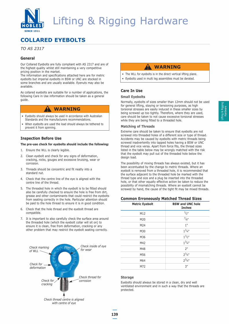
Check marking of WLL
Check inside of eyefor wear
Check for deformation
Check thread forcorrosionCheck for
cracking
Check thread centre is aligned with centre of eye
Lifti
ng &
Rig
ging
Hard
ware
Lifting & Rigging Hardware
06 Lifting & Rigging Hardware.qxd 15/2/12 5:40 PM Page 21

140
COLLARED EYEBOLTS
Threaded AttachmentWhere an eyebolt is used in an untapped hole, the thread shouldengage a nut with a thread length of at least the full thickness ofa standard sized nut.
Where an eyebolt is used with a tapped hole in a plate the lengthof thread engagement should be at least the nominal diameter ofthe thread. Where the undercut is not sufficient to allow for anadequate engagement of the collar, a parallel washer beneath thecollar should be used so that an adequate engagement isachieved.
If the nut side of the eyebolt is on a tapered surface, such as theinside flange of an RSJ beam, then a tapered washer should beused.
Tightening Of EyeboltsEyebolts should be screwed fully down to the face of the liftedload; however, excessive tightening of the eyebolt should beavoided. It should not be possible to enter a 0.04 mm feelergauge at any position between the collar of an eyebolt and itsseating. Where this condition is not achieved, any non-axialloading may overstress the screw thread.
Alignment Of EyeWhere correct alignment of the eye of an eyebolt is required butnot accomplished at the first fitting, it should be achieved by thefollowing methods:
(a) Fitting a shim washer of steel under the collar. A shim washershould not be less in diameter than the diameter of the collar,and the thickness should be between 50% and 100% of thepitch of the threaded shank.
(b) Machining the underside of the collar. The amount of materialmachined from the collar should not exceed 50% of the pitchof the thread on the shank of the eyebolt.
Continuous SlingsA continuous sling should not be used with pairs of eyebolts.Where a continuous sling is used with a pair of eyebolts, the loadapplied to the eyebolts is considerably increased by the tension inthe horizontal portion of the sling and this may overstress theeyebolts. Whenever lifting with eyebolts in pairs supported byslings, always use rigging assemblies with individual sling lengths.
Loading Not Aligned With Threaded EndWhere the centre-line of loading is not in line with the axis of thethreaded end of the eyebolt, including where a two-leg sling isconnected to a pair of eyebolts to support a load, the followingapply:
(a) The diameter of the boss of the tapped hole, into which theeyebolt is screwed, should be no less than the diameter of thecollar of the eyebolt.
(b) The angle between the centre-line of the loading on the eye ofthe eyebolt and the plane containing the eye of the eyeboltshould not exceed 5°, unless an adequate reduction is madeto the WLL.
Where the perpendicular loading is applied (sometimes called‘trunnion lifting’), the eye of the eyebolt should be aligned in thevertical plane.
Where two pairs of eyebolts are fitted to a single item, liftingshould be effected by means of two two-leg slings and a spreaderbar to ensure the load is distributed evenly across the eyebolts.This arrangement also allows the load to be readily applied toeach eyebolt in the plane of the eye.
Attachment of slingsEyebolts are not designed to have hooks attached directly tothem. An approved shackle should always be fitted to the eyeboltand the slings are then attached to the shackle.
Working Load Limits On Pairs Of EyeboltsThe Working Load Limits specified in the Australian Standardapplies to a direct vertical loading. Where eyebolts are used inpairs and the lift is taken by means of two-legged slings,allowance must be made for the angle between the sling legs, and the Working Load Limit decreased accordingly.
The table on the following page indicates Working Load Limit oftwo-legged slings with included angles of 30°, 60° and 90°, withthe comparative value when the load is carried through a singleeyebolt.
The load applied to eyebolts, when used in pairs and threadedwith continuous slings, is increased considerably by the tension in the horizontal portion of the slings. It is most important,therefore, that continuous slings are not used. Correct andincorrect methods are indicated.
Correct and incorrect methods of pairing sling legswith eye bolts
WARNINGWhere a single eyebolt is used care should be taken to ensure thatit remains screwed home throughout the lifting operation. If asingle eyebolt is used for lifting and there is a possibility that theload will rotate or twist, a swivel should be used in the system toprevent the eyebolt unscrewing.
WARNING• Never lift with an eyebolt that is not correctly seated on its collar.
A dangerous condition is created when incorrectly seated eyebolts are loaded.
• Never use excessive leverage to tighten an eyebolt. Excessive tightening will cause stretching and deformation of the thread resulting in a dangerous condition.
Correct
Incorrect Incorrect
CorrectLifting & Rigging
Hardware
Lifting & Rigging Hardware
06 Lifting & Rigging Hardware.qxd 15/2/12 5:40 PM Page 22

141
COLLARED EYEBOLTSTO AS 2317
StockCode
WLL(Tonnes)
Nominal Size
(Metric)A
Nominal Size
(Imperial)A
B(mm)
C(mm)
D(mm)
E(mm)
F (mm)
DELM10 0.25 M10 3/8” 21 14 9 19 18
DELM12 0.40 M12 1/2” 28 19 11 24 23
DELM16 0.80 M16 5/8” 35 24 15 31 30
DELM20 1.60 M20 3/4” 42 29 16 35 40
DELM22 2.00 M22 7/8” 50 33 20 41 41
DELM24 2.50 M24 1” 57 38 22 48 46
DELM30 4.00 M30 1 1/8” 71 48 28 65 50
DELM33 5.00 M33 1 1/4” 71 48 28 65 50
DELM36 6.30 M36 1 1/2” 86 55 33 73 66
DELM39 7.00 M39 1 1/2” 86 55 33 73 66
DELM42 8.00 M42 1 3/4” 102 66 40 90 77
DELM48 10.00 M48 2” 115 72 49 99 89
DELM56 15.00 M56 2 1/2” 143 95 56 124 111
DELM64 20.00 M64 2 1/2” 143 95 56 124 111
DELM76 30.00 M76 3” 163 106 66 140 125
• Nobles collared eyebolts are blue powder coatedfor extra protection.
• Nobles collared eyebolts have the WLLembossed on the body and the thread sizestamped underneath the thread to reduce therisk of incorrect matching of the thread to thetapped hole.
• UNC and BSW sizes available• Collared Eyenuts are also available
Single Eyebolt
WLL TONNES
M10M12M16M20M22M24M30M36M42M56M64
Nominalsize of eyebolt
Axial (WLL)
0.250.400.801.62.02.54.06.38.0
15.020.0
0.060.100.200.400.500.621.001.572.03.75.0
0.120.200.400.801.001.252.03.14.07.5
10.0
0.310.501.002.02.53.15.07.9
10.018.925.0
0.200.320.641.281.602.03.25.06.4
12.016.0
0.120.200.400.801.001.252.03.14.07.5
10.0
Trunnion-typemounting
Perpendicular Included angle 30° Included angle 60° Included angle 90°
Pair of Eyebolts (see note)
1 0.25 0.25 0.63 0.40 0.25
Note: The included angle, between the legs of every two-leg sling connected to a load by a pair of eyebolts, should not exceed 90°.
Reduction factor for single eyebolt
Lifti
ng &
Rig
ging
Hard
ware
Lifting & Rigging Hardware
06 Lifting & Rigging Hardware.qxd 15/2/12 5:40 PM Page 23

142
STARPOINT VRS EYEBOLT
Shape: Star shaped is a clear distinction from standard eye bolt.
Colour: Striking fluorescent pink powder coating.
Marking: Clear indication of WLL (in metric tonnes and lbs) for side load direction F (not allowed with standardeye bolt).
• Forged material 1.6541, alloy quenched and tempered, 100 % electromagnetic crack detected according to EN 1677-4
• Safety factor 4 : 1.• Workpiece material must conform to minimum steel quality
S235JR (do not use with cast iron payloads). • Countersink of tapped hole = nominal thread diameter. • VRS must be able to rotate by 360° in bolted condition.• Adjust to load direction before loading.• Specifically engineered Class 12.9 captive hexagon
socket screw.
Will rotate 360°
Type F1 WLL(t) A B C D E G K M N S Weight
(kg)
COVRSFM08 0.4 34 11 8.5 25 25 28 47 8 6 16 0.1
COVRSFM10 0.4 34 11 8.5 25 25 28 47 10 6 15 0.1
COVRSFM12 0.75 42 13 10 30 30 34 56 12 8 18 0.2
COVRSFM16 1.5 49 15 14 35 35 40 65 16 10 22 0.3
COVRSFM20 2.3 57 17 16 40 40 50 75 20 12 27.5 0.5
COVRSFM24 3.2 69 21 19 48 48 60 90 24 14 33 0.9
COVRSFM30 4.5 86 26 24 60 60 75 112 30 17 41.5 1.7
COVRSFM36 7 103 32 29 72 75 90 135 36 22 49.5 2.9
COVRSFM42 9 120 38 34 82 85 105 158 42 24 58 4.6
COVRSFM48 12 137 43 38 94 100 120 180 48 27 66 7
Type VRS-F is delivered with an integrated installation tool. Just engage the tool into the hexagon socket screw and tighten.STARPOINT is then adjustable 360°.
All dimensions in mm. Also available in UNC threads 3/8” to 2”
VRS-F fixed Adjustable
Lifting & RiggingHardware
Lifting & Rigging Hardware
06 Lifting & Rigging Hardware.qxd 15/2/12 5:40 PM Page 24

143
VLBG LOAD RING
Will rotate 360°
All dimensions in mm.
Also available in UNC threads 1/2” to 1 1/4”
WARNING• The load ring must be installed perpendicular to the work
piece. The work piece must be flat, providing completecontact for the load ring bushing.
• Load ring has to be adjusted in pull direction, free to move,and must not support on edges.
• Use acc. to user instructions and by trained persons• The lifting attachment must be free to move when attached
to the load ring!• Regular inspections should be carried out by a competent
person.• Load should not be turned during lifting.
Type WLL(Tonne)
A B C D F G HStand
HMax
J K LStand
LMax
N SW R T Weight(kg)
Torque(Nm)
COVLBGM08 0.3 30 54 34 35 10 29 11 76 75 45 40 105 5 13 32 75 0.3 30
COVLBGM10 0.63 30 54 34 36 10 29 16 96 75 45 45 125 6 17 32 75 0.32 60
COVLBGM12 1 32 54 34 37 10 29 21 116 75 45 50 145 8 19 32 75 0.33 100
COVLBGM16 1.5 33 56 36 46 13.5 36 24 149 87 47 60 85 10 24 38 85 0.55 150
COVLBGM20 2.5 50 82 54 55 16.5 43 32 187 113 64 75 230 12 30 48 110 1.3 250
COVLBGM24 4 50 82 54 58 18 43 37 222 130 78 80 265 14 36 48 125 1.5 400
COVLBGM30 5 60 103 65 80 22.5 61 49 279 151 80 110 340 17 46 67 147 3.1 500
COVLBGM36 8 77 122 82 100 26.5 77 63 223 205 110 140 300 22 55 85 197 5.8 800
COVLBGM42 10 77 122 82 103 26.5 77 73 273 205 110 150 350 24 65 85 197 6.4 1000
COVLBGM4215 15 95 156 100 113 36 87 63 263 230 130 150 350 24 65 100 222 11.2 1500
COVLBGM48 20 95 156 100 117 36 87 73 303 230 130 160 390 27 75 100 222 11.6 2000
Standard type
Max.lengthwithwasherand nut
Load direction:Permissible only within the green range.
not r
ecom
men
ded
• RUD Universal bolts and nuts for VLBG - 100 % crack detected!• The hex-head-bolt is suitable for internal and external wrench
mounting for types with metric threads.• Surface protection: CORRUD - DT - at least 20 times better
corrosion protection than zinc plating (except for the spot face)after length shortening.
• Thread over whole bolting length "H". • Bolt is held captive in the body. Replace only with the same
quality class bolt.• Clear identification at the bolt head: RUD, thread size,
quality class.
Lifti
ng &
Rig
ging
Hard
ware
Lifting & Rigging Hardware
06 Lifting & Rigging Hardware.qxd 15/2/12 5:40 PM Page 25

144
VLBG LOAD RING - LONG BOLT
• Omni-directional
• RUD crack tested Class 10.9 longer bolt
• Can be cut to suit specific applications
• In-built clamping spring secures ring in flat position
• Load ring manufactured from Grade 100 material
• Rotates through 360˚
• Fully rated for loading in any direction
Stock Code WLL(tonnes)
A(mm)
B(mm)
C(mm)
Weight(kg)
COVLBGLM08 0.3 8 34 60 0.4
COVLBGLM10 0.63 10 34 77 0.4
COVLBGLM12 1.0 12 34 91 0.5
COVLBGLM16 1.5 16 36 116 0.8
COVLBGLM20 2.5 20 54 152 1.7
COVLBGLM24 4.0 24 54 176 2.3
COVLBGLM30 5.0 30 65 213 5.1
COVLBGLM36 8.0 36 82 158 8.3
COVLBGLM42 10.0 42 80 198 10.4
COVLBGLM4215 15.0 42 100 188 14.4
COVLBGLM48 20.0 48 100 223 17.0
VWBG-V SWIVEL RING BOLT
• Metric coarse thread
• Rotates through 360˚
• Longer bolts available upon request
Stock Code WLL(tonnes)
A(mm)
B(mm)
C(mm)
Weight(kg)
COVWBGVM08 0.3 8 29 12 0.25
COVWBGVM10 0.45 10 29 15 0.30
COVWBGVM12 0.6 12 35 21 0.40
COVWBGVM16 1.3 16 35 30 0.60
COVWBGVM20 2.0 20 35 33 1.10
COVWBGVM24 3.5 24 40 40 2.70
COVWBGVM30 5.0 30 50 50 5.50
Lifting & RiggingHardware
B
C
A
B
CA
Lifting & Rigging Hardware
Dimension C = Effective length when supplied with 2 nuts and a washer
06 Lifting & Rigging Hardware.qxd 15/2/12 5:40 PM Page 26

145
POWERPOINT STAR
Will rotate 360°
• Double ballbearing for free turning and soft winding.
• Suitable for all lifting/lashing attachments such as hooks, rings and slings.
• Non-protruding hook tip.
• Forged safety latch engages in the tip of the hook and isprotected against lateral bending.
• Triple coiled corrosion protected double leg spring.
• Thickened tip of the hook prevents handling malpractices andresists bending.
• Wearing edges on both sides and gauge marks for measuringthe width of the hook opening.
• Not suitable for permanent swivelling under load.
• Even under full load, can be rotated in a 90 degree positionfrom the bolt centre line.
Type WLL(t)
A B C D E FStand
FVario
G H M SW Weight(kg)
COPPS063 0.63 13 75 18 40 116 18 19-145 41 33 12 36 0.4
COPPS15 1.5 20 97 25 46 147 24 26-180 50 40 16 41 1
COPPS25 2.5 28 126 30 61 187 30 31-200 61 47 20 55 1.7
COPPS40 4 36 150 35 78 227 36 37-255 70 60 24 70 3.2
COPPS50 5 (6.7) 37 174 40 95 267 45 46-330 93 71 30 85 7.2
COPPS80 8 (10) 49 208 48 100 310 54 55-300 102 76 36 90 9.2
All dimensions in mm. Also available in UNC threads 1/2” to 1 1/2”
WPP-B RING CONNECTION
• The WPP-B is a ring connection for hook assemblies which iswelded in place, providing a simple and reliable lashing pointin a variety of applications.
• Like all WPP products it features the PowerPoint double ballbearing for smooth and reliable 360 degree swivelling in orderto provide the full working load performance in any direction.
• It's unique design can even be turned in a 90 degree positionunder full load from the centre line.
• PLEASE NOTE this is not suitable for permanent swivellingunder full load.
StockCode
WLL(Tonne)
Weightkg/pc
A(mm)
B(mm)
C(mm)
D(mm)
E(mm)
G (mm)
R1(mm) Weld
COWPPB063 0.63 0.35 9 65 35 40 105 40 15 3.5
COWPPB15 1.5 0.6 11 65 35 46 115 50 15 4.5
COWPPB25 2.5 1.0 13 74 40 61 135 61 18 HV3+4.5
COWPPB4 4.0 2.3 16 95 45 78 172 77 20 HV3+5
COWPPB5 5.0 (6.7) 4.7 19 130 60 95 223 93 25 HV3+8
COWPPB8 8.0 (10) 5.3 24 140 65 100 242 102 28 HV3+10
( ) Increased WLL in axial load direction
C
E
GB
A
ØD
R1
Lifting & Rigging Hardware
Lifti
ng &
Rig
ging
Hard
ware
Gauge marks to determine if overloaded
06 Lifting & Rigging Hardware.qxd 15/2/12 5:40 PM Page 27
146
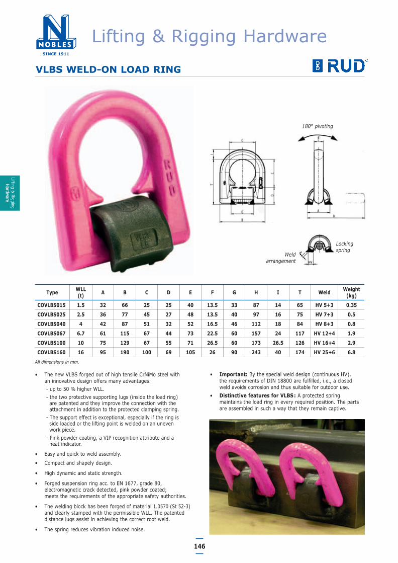
VLBS WELD-ON LOAD RING
• The new VLBS forged out of high tensile CrNiMo steel with an innovative design offers many advantages.- up to 50 % higher WLL.- the two protective supporting lugs (inside the load ring)
are patented and they improve the connection with theattachment in addition to the protected clamping spring.
- The support effect is exceptional, especially if the ring is side loaded or the lifting point is welded on an uneven work piece.
- Pink powder coating, a VIP recognition attribute and a heat indicator.
• Easy and quick to weld assembly.
• Compact and shapely design.
• High dynamic and static strength.
• Forged suspension ring acc. to EN 1677, grade 80,electromagnetic crack detected, pink powder coated; meets the requirements of the appropriate safety authorities.
• The welding block has been forged of material 1.0570 (St 52-3)and clearly stamped with the permissible WLL. The patenteddistance lugs assist in achieving the correct root weld.
• The spring reduces vibration induced noise.
180° pivoting
Weldarrangement
Lockingspring
• Important: By the special weld design (continuous HV), the requirements of DIN 18800 are fulfilled, i.e., a closedweld avoids corrosion and thus suitable for outdoor use.
• Distinctive features for VLBS: A protected springmaintains the load ring in every required position. The partsare assembled in such a way that they remain captive.
Type WLL(t) A B C D E F G H I T Weld Weight
(kg)
COVLBS015 1.5 32 66 25 25 40 13.5 33 87 14 65 HV 5+3 0.35
COVLBS025 2.5 36 77 45 27 48 13.5 40 97 16 75 HV 7+3 0.5
COVLBS040 4 42 87 51 32 52 16.5 46 112 18 84 HV 8+3 0.8
COVLBS067 6.7 61 115 67 44 73 22.5 60 157 24 117 HV 12+4 1.9
COVLBS100 10 75 129 67 55 71 26.5 60 173 26.5 126 HV 16+4 2.9
COVLBS160 16 95 190 100 69 105 26 90 243 40 174 HV 25+6 6.8
All dimensions in mm.
Lifting & Rigging Hardware
Lifting & RiggingHardware
06 Lifting & Rigging Hardware.qxd 15/2/12 5:40 PM Page 28

147
VRBS WELD-ON LOAD RING
X
180° pivoting
Weld arrangementDistance
lugs
Type WLL(t) A B C D E F O Q X T Weld
HV+LaWeight
(kg)
COVRBS040 4 62 14 28 48 135 71 17 77 14 65 HV 4+3 0.8
COVRBS067 6.7 88 20 39 60 170 91 23 101 15 84 HV 5.5+3 2.1
COVRBS100 10 100 22 46 65 195 100 28 106 22 95 HV 6+4 2.8
COVRBS160 16 130 30 57 90 265 134 36 147 28 127 HV 8.5+4 6.6
COVRBS300 30 160 42 78 130 375 195 47 220 37 178 HV 15+4 19
COVRBS500 50 240 70 120 230 620 340 65 380 - 313 HV 25+8 85
All dimensions in mm.
• Distribution of the load force due to the 2 point fixing, hencean optimised force introduction to the work piece.
• Forged, suspension ring acc. to EN 1677-1, electromagneticcrack detected, pink powder coated. Suspension ring can alsobe ordered single. For instance VRL 4.
• Lays flat when not in use.
• Low profile.
• Practical shaped design.
• High dynamic and static strength.
• The welding blocks are forged out of the ideal weldable steelST52-3N (S355J2+N) and the nominal WLL is embossed.
• Patented distance lugs assist in achieving the correct root weld
• The weld arrangement (continuous HV weld) fulfils the requirements of DIN 18800 i.e. the closed weld avoidscorrosion and is thus suitable for outdoor use.
Note: Refer to the RUD user welding instructions!
Ring-VRL
VRBS/VRBS(F)VRBS/VRBS(F)
Lifting & Rigging Hardware
Lifti
ng &
Rig
ging
Hard
ware
06 Lifting & Rigging Hardware.qxd 15/2/12 5:40 PM Page 29
148
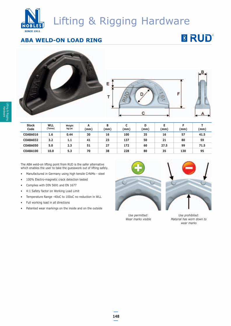
ABA WELD-ON LOAD RING
StockCode
WLL(Tonne)
Weightkg/pc
A(mm)
B(mm)
C(mm)
D(mm)
E(mm)
F(mm)
T(mm)
COABA016 1.6 0.44 30 16 100 35 16 57 41.5
COABA032 3.2 1.1 41 23 137 50 21 80 59
COABA050 5.0 2.3 51 27 172 60 27.5 99 71.5
COABA100 10.0 5.3 70 38 228 80 35 130 95
The ABA weld-on lifting point from RUD is the safer alternativewhich enables the user to take the guesswork out of lifting safely.
• Manufactured in Germany using high tensile CrNiMo - steel
• 100% Electro-magnetic crack detection tested
• Complies with DIN 5691 and EN 1677
• 4:1 Safety factor on Working Load Limit
• Temperature Range -40oC to 100oC no reduction in WLL
• Full working load in all directions
• Patented wear markings on the inside and on the outside
Use permitted:Wear marks visible
Use prohibited:Material has worn down to
wear marks
Lifting & Rigging Hardware
Lifting & RiggingHardware
06 Lifting & Rigging Hardware.qxd 15/2/12 5:40 PM Page 30

149
VABH-W WELDED EXCAVATOR HOOK
Used as a lifting point on lifting beams and spreader bars for wirerope slings, round slings and lifting attachments with an ovalsuspension ring or eye.
• Extremely robust safety latch protected by a ridge.
• Ideally welded in the direction of pull.
• Non-protruding tip of the hook - no unintentional hooking in.
• Enlarged hoook tip avoids improper use in smaller openings.
• Patented wear marks on the hook.
• Measureable overload indicator.
StockCode
WLL(Tonne)
Weightkg/pc
MW(mm)
A(mm)
B(mm)
C(mm)
F(mm)
I(mm) Weld
COVABHW15 1.5 0.8 25 7.5 78 117 70 38 3
COVABHW25 2.5 1.8 30 8.5 101 148 85 49 3
COVABHW40 4 3.1 35 11 122 171 104 59 4
COVABHW67 6.7 5.9 40 13 156 208 120 70 5
VABH-B BOLTED EXCAVATOR HOOK
Used as a lifting point on lifting beams and spreader bars for wirerope slings, round slings and lifting attachments with an ovalsuspension ring or eye.
• Extremely robust with forged safety latch.
• Supplied with RUD special bolts 100% crack detected andprovided with special corrosion protection.
• Non-protruding tip of the hook - no unintentional hooking in.
• Enlarged hoook tip avoids improper use in smaller openings.
• Patented wear marks on the hook.
• Measureable overload indicator.
StockCode
WLL(Tonne)
Weightkg/pc
MW(mm)
A(mm)
B(mm)
C(mm)
F(mm)
G (mm)
H(mm)
I(mm)
L(mm)
RUDBolt
COVABH15 1.5 0.78 25 6.5 78 117 70 48 60 38 15 4 x M10
COVABH25 2.5 1.73 30 7.5 101 148 85 60 75 49 18 4 x M12
COVABH40 4 3 35 10 122 171 104 70 90 59 25 4 x M16
COVABH67 6.7 5.6 40 12 156 208 120 85 110 70 30 4 x M20
Lifting & Rigging Hardware
Lifti
ng &
Rig
ging
Hard
ware
Gauge marks to determine if overloaded
06 Lifting & Rigging Hardware.qxd 15/2/12 5:40 PM Page 31

150
CONCRETE LIFTING CLUTCHES
• SwiftLift Concrete Lifting Clutches have been exclusivelydesigned and approved for use with Reid SwiftLift Anchors.
• They are available in a range of Working Load Limits.
• They have been designed so that they cannot spontaneouslydisengage whlist the system is under load at any orientation,provided they are connected to the head of the correct anchorin the recess. When the lift is complete and the load released,the clutch is quickly and simply disengaged.
Stock Code WLL (Tonne) Pack Qty
GSSL1.3 1.3 1
GSSL2.5 2.5 1
GSSL5.0 5.0 1
GSSL10 10.0 1
GSSL20 20.0 1
GSSL32 32.0 1
Disconnect Loads from BelowIt is common to place pre-fabricated structures and sections intoposition via crane, where the most convenient and stable point forlifting will be at the top of the load. Nobles Ratchet Shackles offeran economical solution, permitting disconnection remotely frombelow.
Ratchet SystemSimply attach lanyards of sufficient length to each end of theactuating belt. The ratchet wheel and handle are actuated byworking the belt back and forth. This action winds the pin out inone direction only.
SafetyFor safety, the shackle pin must be fully wound in. The pin has anextension piece that extends past the winding handle when the pinis not fully wound in.
StockCode
WLL(Tonne)
Approx. Mass(kg)
A(mm)
B(mm)
C(mm)
D(mm)
E(mm)
NSRRS150 15 29 50 125 45 45 40
NSRRS250 25 41 50 225 50 60 45
NSRRS400 40 59 50 245 60 70 70
WARNING• Improper use of this product could result in death or
serious injury.• Never exceed the Working Load Limit.• Ratchet shackles are rated for loading in tension only.• Ratchet release shackles are not to be side loaded.• Ratchet release shackles are not intended to release under load!
Tension must be relaxed prior to pin extraction.• The lug hole cut into the load must be appropriately designed for
the mass being lifted.• Interfacing rigging must be correctly sized and properly secured• Never weld any part of the assembly without consulting Nobles
NOBLES RATCHET SHACKLES
Other sizes and capacities can be manufactured on request.
Lifting & Rigging Hardware
Lifting & RiggingHardware
06 Lifting & Rigging Hardware.qxd 15/2/12 5:40 PM Page 32