060626_temple_mills_bridge_reconstruction_javad_akhtar
TRANSCRIPT

School of
Engineering and Design
First International Conference on Advances in Bridge Engineering
Bridges - Past, Present and Future
co-sponsored by
“Celebrating the 200th Birth
Anniversary of Isambard
Kingdom Brunel”
www.brunel.ac.uk/about/acad/sed/bec2006
to be held at Brunel University, West London
26-28th June 2006

Proceedings of the First International Conference on Advances in Bridge Engineering 26 - 28 June 2006
TEMPLE MILLS BRIDGE RECONSTRUCTION
Temple Mills Bridge Reconstruction
Javad Akhtar
Hyder Consulting (UK) Ltd.
Abstract
Temple Mills Bridge built in 1963, carries the A106, over the River Lea in five spans. The original bridge decks of 50m overall length, consist of precast, prestressed concrete beams with in situ concrete infill, supported on piled reinforced concrete piers and abutments. Extensive chloride contamination and difficult maintenance issues led to the decision to replace the structure. A number of alternative deck replacement solutions were examined – including complete “encapsulation” within new precast concrete arches.
Careful risk management played an important part in being able to develop the most economical solution within the framework of a design and build contract under NEC Option C conditions of contract. Review of geotechnical data and concrete testing concluded that the existing foundations were acceptable for re-use. The replacement adopted a similar span arrangement, but with a deck of semi-integral construction, bearings only being provided at the abutments. The original piers were demolished down to river foundation level and new ones built up with epoxy coated reinforcement below river level. The abutments were extended to form a series of plinths for the bearing shelf with existing faces encased in a 100mm thick skin of new concrete. piers.
A wide range of Environmental mitigation measures were undertaken, including hydraulic design to cater for future “Global Warming”. The design allows for the passage of small mammals along the river-banks and bat roosting facilities. The environmental management plan included a range of measures to mitigate noise and pollution threats.
Keywords: Bridge Reconstruction, Rehabilitation, Concrete Repair, precast prestressed, foundations, environmental, traffic management, GGBFS, PFA, DPS, epoxy coated reinforcement.

Proceedings of the First International Conference on Advances in Bridge Engineering 26 - 28 June 2006
TEMPLE MILLS BRIDGE RECONSTRUCTION
1.0 Background
Temple Mills Bridge is sited an Olympic champion’s stone’s throw from the site of the main Olympic Park in Stratford. The bridge, built in 1963, carries one of the area’s major routes, the A106, over the River Lea. The existing bridge consists of two nearly identical structures, 50 metres long, each carrying a three lane carriageway, a footway/cycleway and a central paved verge. The bridge decks are separated by a 3.66 metre gap and consist of precast, prestressed concrete beams with in situ concrete infill. Each five-span bridge structure is supported on reinforced concrete piers and abutments supported on piles. Unusually, the piers are articulated by means of bearings halfway up the pier, with a concrete ‘hinge’ detail at the top. Whilst many parts of the structure were judged beyond economic repair, the river foundations and the abutment supports were re-used.
Due to the high traffic volumes in the area, the replacement took place in two parts with traffic diverted initially all to the south carriageway while demolition and reconstruction of the North Carriageway was undertaken. By careful re-assessment of the existing deck four lanes were maintained for traffic, and services diverted to the other side.
2.0 Defects in original structure
Most of the problems with the bridge stem from inadequate waterproofing at the time of construction. The bridge was built just before the Highways Agency (HA) introduced specific requirements for waterproofing. The bitumen impregnated jute used at the time has failed to prevent water ingress, to the point that stalactites had formed on extensive areas at the underside of the bridge deck. The water ingress had also caused the sliding bearings of the abutments to seize to a point where they were beyond repair.
Previous investigations had also revealed that reinforcement corrosion due to chloride attack in the insitu concrete “stitch” over the piers had progressed to the point that the deck could no longer sustain the applied hogging moment over the piers due to vehicle loading on the continuous deck.
Fortunately, the original contractor had designed beams to cater for simply supported loading conditions, rather than attempt to refine the design to suit the actual complex continuous frame system. Thus, although the bridge is currently not supporting the applied loading in the manner intended by the designer, the reserve of strength in the beams has saved it from a more imminent demise.
A further concern with the structure was that a “mechanism” type failure mode of the piers was possible due to the presence of bearings at the lower part of the piers and the loss of moment restraint due to corrosion of reinforcement in the insitu concrete stitch at the top of the pier. This failure mode was only prevented by the restraint provided by the abutment curtain wall and the seized abutment bearings. Furthermore parapets did not conform to current standards.
These concerns over long-term structural behaviour and the whole life costs of a growing programme of investigation, monitoring and repair led to Hackney Council’s decision to replace the structure.
3 Project/Risk Management
Hyder Consulting was appointed by the London Borough of Hackney in 2003 as Project Managers to review and consolidate the findings of previous studies, to develop the options for the crossing and to supervise the detailed bridge design and construction phases. In February 2004, contractor Norwest Holst with Designers Mouchel Parkman started the £2 million, 18 month design and build project to replace the existing bridge.

Proceedings of the First International Conference on Advances in Bridge Engineering 26 - 28 June 2006
TEMPLE MILLS BRIDGE RECONSTRUCTION
3.1 Pre-contract Planning
Prior to letting the design and construction contract, the following steps were undertaken: • Scheme, program & procurement strategy review with LB Hackney • Stakeholder Consultation • Technical Investigations and Studies (Hydraulic Flow Modelling, Traffic Counts, Traffic Modelling,
Site Investigations, Planning Review, Environmental Appraisal, Contaminated Land investigation etc. • Design performance criteria and specifications • Preparation of reference designs • Contract Documents • CDM Risk Assessment and Pre-Tender Health & Safety Plan
These processes are illustrated on the figure 1.
3.2 Contract Strategy
The “ideal” form of construction contract was initially considered as NEC Form A for simplicity of administration and price certainty. However this was changed to NEC Option C to meet LBH accelerated program and to allow early letting of the design and construct contract prior to completion of the various investigations and studies. Tender documents were issued Oct 03 (two months after Hyder appointment). Tender evaluation was based on a 60:40 Quality: Price weighting.
3.3 Risk Management The key risks identified at project planning stage are given in Table 1 below, with a brief indication of mitigation measures. During construction a much more extensive Risk Register was developed based on contractual “Early Warnings”. Table 1 Perceived Risks and Proposed Mitigation Measures
Risk Comment/Mitigation Travellers not moving Two separate Traveller Community encampments were present adjacent
to the site. Sensitive discussion and liaison resulted in peaceful relocation of these communities.
Geotechnical - Lack of Information/ reuse of existing foundations (abutment & river piles/pedestals)
An extensive amount of Ground Investigation data was obtained from Transport for London (TfL) archives relating to the A12 Project. Further Site Investigations were instigated during the course of the contract.
Construction unknowns Dealt with through contractual “Early Warning” register. Environment Agency (EA) requirements & timing of responses
Maintained close contact with relevant responsible officers within EA. Extensive hydraulic and environmental studies undertaken.
Potential Traffic Problems Traffic studies undertaken and flows modelled to prove feasibility. Close liaison with Police, TfL, Buses and transport operators.
Public Objection Extensive consultations and publicity. Identification of key stakeholders and planning to minimise impacts.
Control of Construction Costs and planning of Funding
Administration of contract to limit instructed variations and close liaison with funding authorities, including raising risk awareness and provision of cash-flow forecasts.
Statutory Undertakers (SU’s) requirements and information issue
Early development of plans with SU’s and close liaison.
Major Sewers (syphon+Chambers) under bridge at river bed level
Close liaison with Thames Water Utilities. Provision of protective measures.

Proceedings of the First International Conference on Advances in Bridge Engineering 26 - 28 June 2006
TEMPLE MILLS BRIDGE RECONSTRUCTION
4 Alternatives Considered
One of the options considered during project planning stage was the propping and encapsulation of the existing structure on precast concrete arches launched from the existing river foundations. While this option would have avoided demolition with the associated requirements for traffic and services diversions, it was ruled out in conjunction with the Environment Agency because of worries over the hydraulic and ecological effects on the River Lea. Indeed, environmental issues are to the forefront generally because of the bridge’s location on the fringes of the Lea Valley Regional Park.
5 Environmental Considerations
One consequence is that the deck of the new bridge will be 0.5 metre higher than the original. This again takes into account some Environment Agency (EA) concerns about a 1 in 100 year flood event with a further 20% allowance for “Global Warming”. Hydraulic studies were scoped and commissioned by Hyder from external consultants – Halcrow, in order to re-assure the EA that the results were indeed independent from the construction team.
The “hard” revetments adjacent to the riverbank have been lined with “Geoweb” plastic mesh infilled with granular material in order to aid soil retention, vegetation growth and habitat creation. A minor surface bank slip adjacent to the structure has been stabilised by willow stakes.
The design of the new structure will also allow for the easier passage of small mammals along the river-banks and will provide for bat roosting facilities. The construction team liaised closely with Hackney Council and the Environment Agency to mitigate potential noise and pollution threats.
5.1 Traffic Modelling
Due to the critical location of the structure, Hackney were anxious to ensure that traffic flows were catered for with minimal disruption. Hyder therefore undertook advance traffic-modelling studies and developed an outline Traffic Management Scheme in liaison with Hackney, Transport for London, emergency services, transport operators and other stakeholders. The planned construction phasing allowed for services diversions, with the new structure also providing spare capacity to cater for future services.
6 Aspects of Design of Replacement Structure
6.4 Structural Form and Deck
Refer to figures 6 and 7 for deck details (from drawings by Messrs Mouchel Parkman). An infilled precast prestressed deck was adopted, continuous and integral over intermediate pier transoms, supported by laminated rubber bearings at abutments. This semi-continuous form minimised any additional lateral loads on the existing concrete bored piled abutments.
6.2 Materials
In order to improve longer term durability, the new bridge was constructed using a Ground Granulated Blast Furnace Slag (GGBFS) concrete mix. This in turn was subject to a two part spray waterproofing.
To prevent environmental pollution of the watercourse, impregnation of the concrete was undertaken using “Deep Penetrating Sealant” rather than Silane. This forms a permanent protective “glass” coating to the outer pores of the concrete that does not require renewal. DPS whilst having a history of use in Norway and other countries, does not previously appear to have been used in the UK.

Proceedings of the First International Conference on Advances in Bridge Engineering 26 - 28 June 2006
TEMPLE MILLS BRIDGE RECONSTRUCTION
6.3 Foundations
The existing 1.5m diameter, 6m deep cylindrical reinforced concrete “Pedestal” foundations were geotechnically appraised for upper and lower bound geotechnical parameters and judged capable of taking the loads from the new structure (which in any case were lower than pre-existing loads).
Contingency risk-management planning was undertaken in case the concrete condition (which would only be apparent once the existing piers were damaged and cofferdams installed) was found to be poor. However in the event the pedestals were found to be in good condition.
Whilst the effects of the enlarged tops of concrete pedestals have been hydraulically modelled and shown to have little impact on the flow of the River Lea, large pieces of concrete from the deck demolition will be placed around the pile cap to mitigate the possibility of scour on the pile caps below the water level. This is being done as a precaution against possible eddy currents under and around the lips of the enlarged pedestals.
Refer to figure 5 New Piers Founded on Existing "Pedestal" Foundations.
7 Construction
Demolition of the original bridge started with the northern carriageway. This initially required the stabilisation of the existing bridge piers and the positioning of pontoons underneath the bridge deck. Hydraulic breakers then moved in to break up the deck, with the debris being scooped up from the pontoons below using small robotic excavators refer to figure 8 Deck Demolition on Pontoons.
As the deck is removed temporary struts were put up to support the piers before removal of these down to river floor level. This was undertaken in two stages, firstly down to the level of the pier bearings, followed by removal of the stubs below the waterline down to the level of the top of the “Pedestal” foundations.
In order to begin the construction of the new piers, precast concrete rings were first embedded around the existing pile caps. As well as creating enlarged pedestals, these served as coffer-dams during the river level works and provided shuttering moulds for the concrete pour of the new piers. Prior to the pour, new epoxy coated reinforcement bars were drilled and resin anchored in to the existing pedestal.
While tests on the loading capabilities of the abutments showed good performance with core test results of 60 KPa, there was evidence of some corrosion of non-structural steel reinforcement in the abutment face due to water leaking in from the top and side of the expansion joints. Mouchel-Parkman, who carried out the detailed design for Norwest Holst, proposed that, the top of the existing abutments be scabbled down and new reinforcement bars resin anchored in at close centres. The abutments were then extended to form a series of plinths for the bearing shelf with existing faces encased in a 100mm thick skin of new concrete.
The buried faces of the abutments were tested and found to have negligible chloride contamination, however due to the uneven concrete finish it was decided to extend the “encapsulation” concrete skin to the rear face of the abutment also.
In the river itself, particular care was required working around the three 1 metre diameter sewage pipes which run longitudinally through the middle of the bridge just below the river floor. In the first stage the pontoons protected these pipes. However it was found that the pontoons grounded easily and would actually obstruct the river in the event of an unforeseen flood event. For demolition of the southern half of the deck the pontoons were omitted and a crash-deck provided - comprising a 300 mm thick granular pad over two layers of steel sheet piles laid flat on the bed (spanning the pipes).

Proceedings of the First International Conference on Advances in Bridge Engineering 26 - 28 June 2006
TEMPLE MILLS BRIDGE RECONSTRUCTION
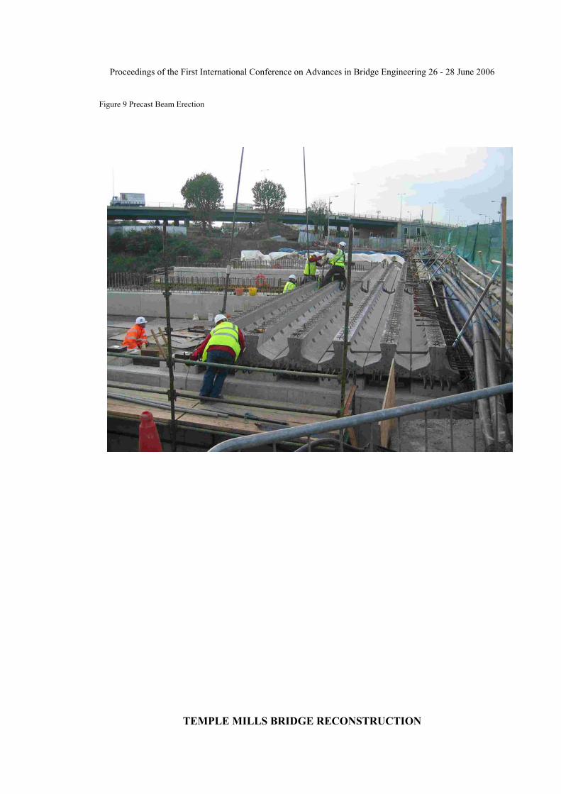
Precast beam erection was undertaken using a mobile crane sited just behind the abutments (refer to figure 9). Difficulties were encountered at the junction between previously erected North Deck and the South deck due to the need to “mesh” into the 3 dimensional reinforcement cage provided out of the cross-head and continuity reinforcement from the pre-erected deck. These were overcome by use of reinforcement couplers.
8 Conclusion
Completion of this bridge in March 2006 secured this important local transport link and marks the first project to cross the finish line at the start of the major developments on the adjacent Olympic site.
Acknowledgements
The author, whose role was as Project Manager, wishes to acknowledge the assistance and support of….
Client Manager Joe Figurado London Borough of Hackney Supervisor Richard Williams Hyder Consulting (UK) Ltd. Contractor Mark McGleenon Norwest Holst Construction Ltd Contractor’s Designer Andrew Foster Mouchel-Parkman Ltd
Figure 1 Pre-Construction Contract Project Management Processes
Figure 2 Existing Bridge

Proceedings of the First International Conference on Advances in Bridge Engineering 26 - 28 June 2006
TEMPLE MILLS BRIDGE RECONSTRUCTION
Figure 3 Installation of Phase 1 Traffic Management

Proceedings of the First International Conference on Advances in Bridge Engineering 26 - 28 June 2006
TEMPLE MILLS BRIDGE RECONSTRUCTION
Figure 4 Scheme Options Considered
Figure 5 New Piers Founded on Existing "Pedestal" Foundations
(Note details slightly modified during construction) Figure 6 Deck Cross-section at Central Reserve

Proceedings of the First International Conference on Advances in Bridge Engineering 26 - 28 June 2006
TEMPLE MILLS BRIDGE RECONSTRUCTION
Figure 7 Deck Long-section at Abutment and Abutment “Encapsulation” Detail Figure 8 Deck Long-section at Abutment and Abutment “Encapsulation” Detail
Figure 8 Deck Demolition
Proceedings of the First International Conference on Advances in Bridge Engineering 26 - 28 June 2006
TEMPLE MILLS BRIDGE RECONSTRUCTION
Figure 9 Precast Beam Erection

Call for papers
The theme of the conference will be ‘Bridges - past,present and future’. Papers can be presented onany aspect of the development of knowledge,techniques, innovations, control, monitoring andmanagement processes which may represent anadvancement in the field of bridge engineering. Aspecial session on Historical Bridges, with particularemphasis on Brunel’s work, is planned to celebrate his200th birth anniversary.
Invited Speakers
The following have indicated acceptance ofinvitations to make Keynote Presentations:
Mr Steven BrindleEnglish Heritage, UK
Prof Jean Armand CalgaroENPC and GCPC, Paris, France
Prof Jacques HeymanCambridge University, UK
Mr Makoto KitagawaHonshu Bridge Authority, Japan
Mr Brian PritchardConsultant, formerly Atkins, UK
Prof Santiago HuertaUniversity of Madrid, Spain
Prof Michael CollinsToronto University, Canada
Requirements and dates
Authors wishing to present a paper should submit anabstract (300 words approx.). Abstracts and Papersmust be in English and should clearly indicate thecontact author details (affiliation, address, telephone,FAX and e-mail). The abstracts may be submitted bypost (Bridge Conference 2006, Research Office,School of Engineering and Design, Brunel University,Uxbridge, UB8 3PH, UK) or e-mail([email protected])
Target dates
Submission of Abstracts 30 December 2005
Acceptance of Abstracts 6 January 2006
Submission of full Manuscripts 28 February 2006
Final acceptance will be based on peer-review of thefull manuscript.
Final Manuscripts should be no more than 8 pages in length and must comply with the'Instructions for Preparing a Paper' available atwww.brunel.ac.uk/about/acad/sed/bec2006
Manuscripts should be submitted via e-mail or the electronic submission form at the conferencewebsite. In exceptional circumstances, fullmanuscripts may be submitted for consideration aspaper hard copy. In all circumstances, a paper hardcopy and an electronic CD-ROM version of the finalmanuscript of the paper must be provided for thepublication process by the due date.
First International Conference on
Advances in Bridge Engineering
www.brunel.ac.uk/about/acad/sed/bec2006
Isambard Kingdom Brunel was a visionary and amongst the most influential engineers of the last millennium.His wide-ranging works, his aesthetic sense and legacy have withstood the test of time and have been aconstant inspiration to generations of engineers. He was a tunnelling engineer, a railway engineer, atransportation engineer, a buildings engineer, a marine engineer but above all he was a bridge engineer. Eventhe general public who have no special knowledge of engineering matters tend to automatically warm to theinherent beauty and merit of his works and contribution, recognising the genius he was. The splendid CliftonSuspension Bridge of his design is an example of this artistry. The University is proud to be named after thisgreat engineer and following his footsteps shall endeavour to advance the frontiers of knowledge andengineering for the future.

Exhibition
There will be an associated exhibition of selectedequipment, instrumentation, software andinformation relating to bridge engineering, providingdelegates an opportunity for exchange of ideas andinformation on topics of current interest in the field.Organisations interested in exhibiting their productsor services should contact the ConferenceAdministrator for terms and conditions.
Venue
Howell Theatre, Brunel University, Uxbridge,Middlesex UB8 3PH.
Booking Conditions
i) Early booking is recommended; places will bereserved on first come first served basis.
ii) Reserved places can be reassigned to anotherperson by prior written request.
v) Delegates are encouraged to travel by publictransport. A limited number of car parking permitswill be available for parking at the University.
vi) All rights reserved with the University.
Application Form: First International Conference on Advances in Bridge Engineering on 26-28 June 2006
For reserving a place, please either register online at www.brunel.ac.uk/about/acad/sed/bec2006 or complete thisapplication form with Conference fee (cheque or transfers made payable to Brunel University) or address forinvoicing to:
Mrs Carole Carr [e-mail: [email protected]]Research Office ManagerBridge Engineering CentreSchool of Engineering and DesignBrunel UniversityUxbridgeMiddlesex UB8 3PH Tel: 01895 266 962 Fax: 01895 269 797
!
Registration Fee
The registration fees for the various categories of participants at the conference, which include a copy of theproceedings, a reception, buffet lunches and refreshments for the 3 days of the conference, are as follows:
Fee received: Before 1 March 2006 From 1 March 2006Delegates £495 €740 £545 €815Authors £445 €665 N/AStudents (proof required) £295 €440 £325 €485Day rate delegates/authors £245 €365 £275 €410

SCHOOL OF ENGINEERING AND DESIGN
102240 0106
Conference Organising CommitteeProf Arvind Kumar Kumar Associates & Brunel UniversityMr Chris Brown Brunel UniversityProf Luiz Wrobel Brunel University
Conference AdministratorMrs Carole Carr Brunel University
Conference Advisory CommitteeProf Ben Barr Cardiff University & Institution of Civil EngineersMr Robert Benaim Robert Benaim & Associates, UKMr Steven Brindle English Heritage, UKProf Jean Armand Calgaro ENPC and GCPC, Paris, FranceMr Michael Chubb Atkins, UKProf Michael Collins Toronto University, CanadaMr Patrick Dallard Arup, UKDr Stuart Davis Mott MacDonald, UKProf Christopher Earls Pittsburgh University, USAMr Ian Firth Flint & Neil Partnership, UKProf Bill Harvey Bill Harvey Associates, UKProf Paulo Helene Sao Paulo University, BrazilProf Jacques Heyman Cambridge University, UKMr Makoto Kitagawa Honshu Bridge Authority, JapanProf Paulo Laurenco Minho University, PortugalMr Angus Low Arup, UKProf Jianming Lu Research Institute of Highways, ChinaProf Claudio Modena Padua University, ItalyMr Graham Nicholson Tony Gee & Partners, UKMr Brian Pritchard Consultant formerly Atkins, UKMr Nigel Ricketts Network Rail, UKProf Charles Roeder Washington University, USAMr Benjamin Sadka Highways Agency, UKProf Berthold Schlecht Technical University Dresden, GermanyProf Fernando Stucchi Sao Paulo University, BrazilMr Keith Wilson Faber Maunsell, UKDr Richard Woodward Transport Research Laboratory, UK
Surname
First Names
Organisation
Position
Address
City
Post Code
Tel
Fax
Date
Fee cheque enclosed £Or Invoicing Address (UK only)
!