071112 captive 2011 text catalog - apex fasteners · self-clinching fasteners specifications are...
TRANSCRIPT
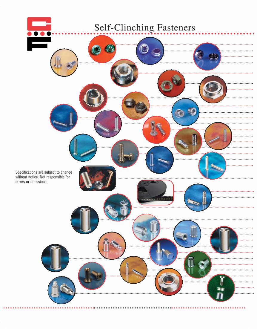
Self-Clinching Fasteners
Specifications are subject to changewithout notice. Not responsible forerrors or omissions.
33716 Captive_2011_Cv_Cover 12/5/12 8:28 AM Page 2

CAPTIVE FASTENER® SERIES DESCRIPTION PAGE
“PEM” is a registered trademark of PennEngineering®
About the Company / Product Description 4-8CFAS, CFAC Self-Clinching Floating Nuts 9-10CFFS, CFFC Self-Clinching Floating Locking Nuts 11-12CFSP Self-Clinching Nuts for Stainless Steel 13-14CFB, CFBS Blind Press Nuts 15-16C / CS Self-Clinching Steel and Stainless Steel Nuts 17-21CFH, CFHN Self-Clinching Steel Heavy Duty Nuts 22CA Self-Clinching Aluminum Nuts 23CKN Self-Clinching KAL-Nuts 24CFL Self-Clinching Flush Nuts 25-26CFE, CFEO Miniature Self-Clinching Self-Locking Fasteners 27-28CFEX, CFEOXCRT Self-Clinching Self-Locking Nuts 29-30CPL, CPLC Self-Clinching Top Collar Lock Nuts 31-32CH, CHS, CHA Self-Clinching Studs, Flush Head 33-35HCH, HCHS, HCHB Self-Clinching Studs, High Torque 36-37HCW Self-Clinching Studs, Wide Head 38-39TCH, TCHS Self-Clinching Studs, Thin Sheet 40-41CHE, CHES Close-to-Edge Studs 42-44CHTS 400 Series Stainless Steel Studs 45-47CFA-1, CFA-2 / CFC-1, CFC-2 Self-Clinching Concealed Head Studs 48-50CH, CHN, CHS, CHA Self-Clinching Pins 51-52CGS Self-Clinching Tapered Guide Pins 53
Broaching Type Fasteners for PermanentMounting in Non-Ductile Materials andPrinted Circuit Boards
CRM Reel Mounted Spacers and Nuts 59CFKSSB Spring-Top Standoffs for PC Boards 60-61CPFK PC Board Panel Fasteners 62LPH-0, 1, 2 Low-Profile Panel Fasteners 63-64CPFC2 Self-Clinching Panel Fastener Assemblies 65-66CFSO, CFSOS, CFSOA Self-Clinching Standoffs 67-73CFBSO, CFBSOS, CFBSOACFSOSG, CFSOAG Self-Clinching Grounding Standoffs 74CF40, CF40S Miniature Self-Clinching Standoffs 75-76CF4-S0, CF4-BS0 400 Series Stainless Steel Standoffs 77-79CFSKC Self-Clinching Slide-Top Standoffs 80-81CFMS Male Self-Clinching Standoffs 82CFSO, CFSOS, CFSOA Unthreaded Thru-Hole Standoffs 83-84CFT, CFTS, CFTA Thin Head Standoffs 85-87CFSSA, CFSSS, CFSSC Spring-Top Standoffs 88-89CFHS-1, CFHS-2 Self-Clinching Concealed Head Standoffs 90-92CFWN, CFWNS Weld Nuts 93-94CFS2, CFR2, CFN2 Panel Screw Components 95-98CPN, CPR Self-Clinching Spring-Loaded Plungers 99-100
Recommended Installation Procedure/Reference Charts 101-105
32011
Table of Contents
CKF2, CKFS2CKFE, CKFSECKFHCKFB3
54-55565758
071112 Captive_2011_Text_Catalog 12/5/12 8:19 AM Page 3

trademarks:
Zinc with clear trivalent chromate, 5µm thickness on all significant surfaces, withstands 12 hours saltspray to white corrosion. Reference applicable sections – ASTM B633, ASTMF1941, ASTMF1941M & ASTM B117.
Zinc with clear trivalent chromate and sealer, 5µm thickness on all significant surfaces, withstands 72 hours saltspray to white corrosion. Reference applicable sections – ASTM B633, ASTMF1941, ASTMF1941M & ASTM B117.
Zinc with colored trivalent chromate, 5µm thickness on all significant surfaces, withstands 96 hours salt spray towhite corrosion. Reference applicable sections – ASTM B633, ASTMF1941, ASTMF1941M & ASTM B117.
2011
Finishes
Available finishes for self-clinching fasteners:
Finish Chromate Suffix RoHsBlack Dry Film Lube -------- ML YesBlack Nitrate -------- BN YesBlack Oxide -------- BO YesBright Acid Tin -------- BT YesCadmium Black CB NoCadmium Yellow CC NoCadmium Clear Cl NoCadmium Dry Film Lube EF NoCopper Flash -------- CF YesCopper, Nickel, Tin -------- CT YesDacromet 320 -------- DM NoElectro Tin -------- ET YesElectro Tin (Matte Finish) -------- MT YesGeomet -------- GM YesLM1293 -------- LM YesNickel over Copper Flash -------- NC YesNickel Plate -------- NI YesNylon Locking Patch -------- NP YesTin Lead -------- TL NoZinc (*) Clear ZI YesZinc with Sealer (**) Clear ZS YesZinc (***) Black ZB YesZinc (***) Blue BZ YesZinc (***) Green ZG YesZinc (***) Red ZR YesZinc (***) Yellow ZC YesNone -------- X YesOther Finishes available upon request
Notes:1. Unless otherwise specified
self clinching fasteners willbe provided with zinc/clearchromate (ZI).
2. P/N Structure example:C632-1 ZC
Finish
3. In accordance with ANSIB1.1(inch) and ANSIB1.13M(metric) specifications,the maximum major diameterand pitch diameter of class2A/6g plated studs can begauged to class 3A/4h.
071112 Captive_2011_Text_Catalog 12/5/12 8:19 AM Page 6

72011
Locking Patch
Note: Minimum Order Quantities Apply. ND Patch® is a registered trademark of ND Industries.
The ND Patch coating process produces a completely dry product that is fused to the fastener and is ready to use right out of the box. ND Patch performs immediately upon assembly with no curing time required.
How ND Patch Works:
When assembled with a mating part the resilient ND Patch is compressed. The compressed engineered plastic (typically a Nylon Patch) provides locking action in the thread instead of at the bearing surface due to its vibration dampening characteristics. In general, the resilience of ND Patch holds the fastener in place without adhesives or thread distortion. Due to its resilience, Patch can be repeatedly adjusted and reused. ND Patch is normally positioned one to three threads back from the end of the fastener to assure ease of starting. The normal coating length of the Patch is four to six threads. Special Patch location and coating length can be specified for specific applications.
Features:
Saves Time: Fasteners coated with ND Patch can be automatically fed through standard feeding devices.
Retains Full Strength: ND Patch process involves no drilling or milling, so there is no loss of the fastener's strength or hardness and any troublesome burrs or chips.
Saves Money: Use of ND Patch eliminates the need for costly lock washers, cotter pins, or castellated nuts. You get a close fit without the costs involved in obtaining close tolerances. Moreover, ND Patch is less expensive than applying bottled thread locking compounds at the point of assembly.
Resists Heat & Cold: ND Patch meets and exceeds IFI Specifications 124 & 524 as well as Military specification MIL-DTL-18240F, Type P, for temperatures from -70°F (-56°C) to +250°F (121°C).
Chemical Resistant: ND Patch will not dry, shrink, or lose resiliency when exposed to commercial solvents, alcohol, gasoline, oil, caustic soda, jet fuel, etc.
Reusable: Fasteners coated with ND Patch can be reused repeatedly without damage to threads. ND Patch is particularly resistant to deformation, which makes it ideal for repeated
071112 Captive_2011_Text_Catalog 12/5/12 8:19 AM Page 7

Note: Minimum Order Quantities Apply. ND LM-1293® is a registered trademark of ND Industries.
ND LM-1293®
ND LM-1293 is an automotive approved process in which fasteners are accurately coated with one of a variety of thread masking and lubricating materials. The use of a Teflon® type material and a proprietary binder system in ND LM1293 makes it the ideal coating for many applications.
Description:
ND LM-1293 can be applied to male or female, ferrous or non-ferrous threaded fasteners of virtually any finish. It is a cross-linked coating providing excellent solvent resistance, high temperature resistance, e-coat resistance (as specified under GM6076-M), resistance to weld spatter, and improvement to torque-tension properties. ND LM-1293 lubricates fastener threads to reduce driving friction, heat buildup, and thread galling in long rundowns while helping to ensure uniform clamp loading. To meet your specific application needs, ND LM-1293 employs a wide range of polymers, including fluorinated ethylene polymer (Teflon®-type) material.
Features:
Reliable Masking: ND LM-1293 prevents undesirable substances such as electro-deposited undercoating, weld spatter and some other materials from adhering to fastener threads.
Low Heat Process: Unlike competitive processes which often subject parts to extremely high temperatures that may damage or discolor the fastener, ND's unique patented process employs minimal heat.
Minimal Pre-cleaning Requirements: Unlike competitive processes that require parts be completely free of oil or other rust preventative coatings, only parts with excess oil or surface contaminants may require pre-cleaning for ND LM-1293 processing.
Increases Productivity: By providing additional lubricity, ND LM-1293 speeds assembly operations and increases productivity.
Eliminates Capping and Plugging: ND LM-1293 eliminates the need to cap male and plug female threads.
Thread Coating
071112 Captive_2011_Text_Catalog 12/5/12 8:19 AM Page 8

92011
Part Number +.003 in. BThread Carbon Stainless D (.08mm) A E ± .015 in. C
Size Steel Steel Max. Min. -.000 (.00) Max. Max. (± .4mm) Max. Min.
#4-40 CFAS440-1 CFAC440-1 .038 .040 .290 .289 .290 .36 .13 .30CFAS440-2 CFAC440-2 .054 .056
#6-32 CFAS632-1 CFAC632-1 .038 .040 .328 .327 .335 .39 .13 .32CFAS632-2 CFAC632-2 .054 .056
#8-32 CFAS832-1 CFAC832-1 .038 .040 .368 .367 .365 .44 .13 .34CFAS832-2 CFAC832-2 .054 .056
#10-24 CFAS1024-1 CFAC1024-1 .038 .040CFAS1024-2 CFAC1024-2 .054 .056 .406 .405 .405 .47 .16 .36
#10-32 CFAS1032-1 CFAC1032-1 .038 .040CFAS1032-2 CFAC1032-2 .054 .056
1/4-20 CFAS420-2† CFAC420-2† .054 .056 .515 .514 .510 .60 .21 .421/4-28 CFAS428-2† CFAC428-2† .054 .056
M3 x 0.5 CFASM3-1 CFACM3-1 .97 1.0 7.37 7.35 7.37 9.1 3.3 7.6CFASM3-2 CFACM3-2 1.37 1.4
M4 x 0.7 CFASM4-1 CFACM4-1 .97 1.0 9.35 9.33 9.28 11.2 3.3 8.6CFASM4-2 CFACM4-2 1.37 1.4
M5 x 0.8 CFASM5-1 CFACM5-1 .97 1.0 10.31 10.29 10.29 11.9 4.3 9.0CFASM5-2 CFACM5-2 1.37 1.4
M6 x 1.0 CFASM6-2† CFACM6-2† 1.37 1.4 13.08 13.06 12.96 15.3 5.3 11.0
Dimensions & Specifications
Series Material Finish
Thread: Internal 2B, ANSI B1.1(6H, ANSI/ASME B1.13M).
Float: .015 in. (.4mm) minimum in all directions from center, .030 in. (.8mm) total.
Use in: Materials with Rockwell Hardness of B-70 or less.
E A
CD
B
CFAS Heat-treated Zinc* ClearCarbon Steel
CFAC 300 Series PassivatedStainless Steel ASTM A380
INCH
(in.
)M
ETRI
C (m
m)
†Not stocked, available on special order.
CFAS & CFAC floating clinch nuts provide a self-clinchingfastener with a floating nut that compensates for mating misalignments to .030 inches (.8 mm).
*See Finish Spec. on Page 6.
STARBURST® design indicates genuine Captive self-clinching Floating Nut.
Floating Clinch Nuts
Series CFAS & CFAC
071112 Captive_2011_Text_Catalog 12/5/12 8:19 AM Page 9

Installation & Performance Data
Cold-rolled Steel 2024-T3 Aluminum 5052-H34 Aluminum
Installation Torque- Installation Torque- Installation Torque-Thread Force Pushout out Force Pushout out Force Pushout out
Size Shank (tons) (lbs.) (in.-lbs.) (tons) (lbs.) (in.-lbs.) (tons) (lbs.) (in.-lbs.)
#4-40 -1 1 – 2 300 85 1 – 2 220 65 .5 – .75 215 65-2 1 – 2 300 150 1 – 2 225 150 1 225 80
#6-32 -1 1 – 2 300 150 1 – 2 235 110 1 240 140-2 1 – 2 300 175 1 – 2 275 150 1 250 150
#8-32 -1 1 – 2 300 150 1 – 2 240 110 1 250 140-2 1 – 2 400 200 1 – 2 300 150 1 265 150
#10-24 -1 1 400 150 1 – 2 300 150 1 300 150-2 2 450 200 1 – 2 300 200 1 350 175
#10-32 -1 1 400 150 1 – 2 300 150 1 300 150-2 2 450 200 1 – 2 300 200 1 350 175
1/4-20 -2 2 – 3 500 325 2 – 3 300 325 1 – 2 400 3251/4-28
Installation Torque- Installation Torque- Installation Torque-Thread Force Pushout out Force Pushout out Force Pushout out
Size Shank (kN) (N) (N•m) (kN) (N) (N•m) (kN) (N) (N•m)
M3 -1 13 1330 9 13 970 7 7 950 7-2 13 1330 16 13 1000 17 9 1000 9
M4 -1 13 1330 16 13 1050 12 9 1100 16-2 13 1775 22 13 1330 17 9 1178 17
M5 -1 15 1775 16 15 1330 17 9 1330 17-2 15 2000 22 15 1330 22 9 1550 22
M6 -2 22 2220 36 22 1330 36 13 1780 36
INCH
(in.
)M
ETRI
C (m
m)
Continued from previous page
Floating Clinch Nuts
Series CFAS & CFAC
071112 Captive_2011_Text_Catalog 12/5/12 8:19 AM Page 10

2011
Part Number +.003 in. BThread Carbon Stainless D (.08mm) A E ± .015 in. C
Size Steel Steel Max. Min. -.000 (.00) Max. Max. (± .4mm) Max. Min.
#4-40 CFFS440-1 CFFC440-1 .038 .040 .290 .289 .290 .36 .19 .30CFFS440-2 CFFC440-2 .054 .056
#6-32 CFFS632-1 CFFC632-1 .038 .040 .328 .327 .335 .39 .20 .32CFFS632-2 CFFC632-2 .054 .056
#8-32 CFFS832-1 CFFC832-1 .038 .040 .368 .367 .365 .44 .21 .34CFFS832-2 CFFC832-2 .054 .056
#10-24 CFFS1024-1 CFFC1024-1 .038 .040CFFS1024-2 CFFC1024-2 .054 .056 .406 .405 .405 .47 .27 .36
#10-32 CFFS1032-1 CFFC1032-1 .038 .040CFFS1032-2 CFFC1032-2 .054 .056
1/4-20 CFFS420-2† CFFC420-2† .054 .056 .515 .514 .510 .60 .31 .421/4-28 CFFS428-2† CFFC428-2† .054 .056
M3 x 0.5 CFFSM3-1 CFFCM3-1 .97 1.0 7.37 7.35 7.37 9.1 4.8 7.6CFFSM3-2 CFFCM3-2 1.37 1.4
M4 x 0.7 CFFSM4-1 CFFCM4-1 .97 1.0 9.35 9.33 9.28 11.2 5.3 8.6CFFSM4-2 CFFCM4-2 1.37 1.4
M5 x 0.8 CFFSM5-1 CFFCM5-1 .97 1.0 10.31 10.29 10.29 11.9 6.8 9.0CFFSM5-2 CFFCM5-2 1.37 1.4
M6 x 1.0 CFFSM6-2† CFFCM6-2† 1.37 1.4 13.08 13.06 12.96 15.3 7.9 11.0
Dimensions & Specifications
Series Material FinishBody Nut Body Nut
Thread: Self Locking Internal 3B, ANSI B1.1(6H, ANSI/ASME B1.13M).
Float: .015 in. (.4mm) minimum in all directions from center, .030 in. (.8mm) total.
Use in: Materials with Rockwell Hardness of B-70 or less.
Threaded TopEliptically Formed
E A
CD
B
Heat-treated 300 SeriesBlack Dry Film
CFFSCarbon Steel Stainless Steel
Zinc* Clear Lubricant** overCadmium Chromate
300 Series 300 Series PassivatedBlack Dry Film
CFFCStainless Steel Stainless Steel ASTM A380
Lubricant** overCadmium Chromate
INCH
(in.
)M
ETRI
C (m
m)
All items subject to minimum order requirements.†Not stocked, available on special order.
CFFS & CFFC floating clinch nuts provide a self-clinching fastener with a floating nut that com-pensates for mating misalignments to .030 inches(.8 mm) and provides prevailing torque for the mating screw equivalent to MIL-N-25027specifications.
*See Finish Spec. on Page 6.** Spec. MIL-L-46010
STARBURST® design indicates genuine Captive self-clinching Floating Nut.
Continued on next page.
Floating Locking Clinch Nuts
Series CFFS & CFFC
071112 Captive_2011_Text_Catalog 12/5/12 8:19 AM Page 11

Installation & Performance Data
Cold-rolled Steel 2024-T3 Aluminum 5052-H34 Aluminum
Installation Torque- Installation Torque- Installation Torque-Thread Force Pushout out Force Pushout out Force Pushout out
Size Shank (tons) (lbs.) (in.-lbs.) (tons) (lbs.) (in.-lbs.) (tons) (lbs.) (in.-lbs.)
#4-40 -1 1 – 2 300 85 1 – 2 220 65 .5 – .75 215 65-2 1 – 2 300 150 1 – 2 225 150 1 225 80
#6-32 -1 1 – 2 300 150 1 – 2 235 110 1 240 140-2 1 – 2 300 175 1 – 2 275 150 1 250 150
#8-32 -1 1 – 2 300 150 1 – 2 240 110 1 250 140-2 1 – 2 400 200 1 – 2 300 150 1 265 150
#10-24 -1 1 400 150 1 – 2 300 150 1 300 150-2 2 450 200 1 – 2 300 200 1 350 175
#10-32 -1 1 400 150 1 – 2 300 150 1 300 150-2 2 450 200 1 – 2 300 200 1 350 175
1/4-20 -2 2 – 3 500 325 2 – 3 300 325 1 – 2 400 3251/4-28
Installation Torque- Installation Torque- Installation Torque-Thread Force Pushout out Force Pushout out Force Pushout out
Size Shank (kN) (N) (N•m) (kN) (N) (N•m) (kN) (N) (N•m)
M3 -1 13 1330 9 13 970 7 7 950 7-2 13 1330 16 13 1000 17 9 1000 9
M4 -1 13 1330 16 13 1050 12 9 1100 16-2 13 1775 22 13 1330 17 9 1178 17
M5 -1 15 1775 16 15 1330 17 9 1330 17-2 15 2000 22 15 1330 22 9 1550 19
M6 -2 22 2220 36 22 1330 36 13 1780 36
INCH
(in.
)M
ETRI
C (m
m)
Continued from previous page.
Floating Locking Clinch Nuts
Series CFFS & CFFC
071112 Captive_2011_Text_Catalog 12/5/12 8:19 AM Page 12

2011
CFSP self-clinching nuts provide strong load-bearing threads instainless sheet metal as thin as .030 inches (.8mm).
Dimensions & Specifications
INCH
(in.
)M
ETRI
C (m
m)
Thread: Internal 2B, ANSI B1.1 (6H, ANSI/ASME B1.13M).Use in: Materials with Rockwell Hardness of B-88 or less.
+.003 in. C DThread Part A (.08 mm) B ± .01 in. ± .01 in.
Size Number Max. Min. –.000 (.00) Max. (±.25mm) (±.25mm) Min.CFSP440-0 .030 .030-.039
#4-40 CFSP440-1 .038 .040 .166 .165 .07 .25 .19CFSP440-2 .054 .056CFSP632-0 .030 .030-.039
#6-32 CFSP632-1 .038 .040 .1875 .187 .07 .28 .22CFSP632-2 .054 .056CFSP832-0 .030 .030-.039
#8-32 CFSP832-1 .038 .040 .213 .212 .09 .31 .27CFSP832-2 .054 .056CFSP1032-0 .030 .030-.039
#10-32 CFSP1032-1 .038 .040 .250 .249 .09 .34 .28CFSP1032-2 .054 .056
1/4-20 CFSP420-1 .054 .056 .344 .343 .17 .44 .34CFSP420-2 .087 .091CFSPM3-0 .76 .8-1
M3 x 0.5 CFSPM3-1 .97 1.0 4.22 4.2 1.5 6.3 4.8CFSPM3-2 1.37 1.4CFSPM4-0 .76 .8-1
M4 x 0.7 CFSPM4-1 .97 1.0 5.41 5.38 2 7.9 6.9CFSPM4-2 1.37 1.4CFSPM5-0 .76 .8-1
M5 x 0.8 CFSPM5-1 .97 1.0 6.35 6.33 2 8.7 7.1CFSPM5-2 1.37 1.4
M6 x 1.0 CFSPM6-1 1.37 1.4 8.75 8.73 4.1 11.1 8.6
D
C
B
A
Self-Clinching Nutsfor Stainless Steel
Series CFSP
Series Material Finish
CFSPPrecipitation
HardenedStainless Steel
PassivatedASTM A380
071112 Captive_2011_Text_Catalog 12/5/12 8:19 AM Page 13

Installation & Performance Data
INCH
(in.
)M
ETRI
C (m
m)
Installation Torque-Thread Shank Force Pushout out
Size Code (tons) (lbs.) (in.-lbs.)-0 125 13
#4-40 -1 1.5 – 2.5 160 16-2 285 17-0 135 17
#6-32 -1 2 – 3.5 165 23-2 335 27-0 140 29
#8-32 -1 2 – 3.5 175 36-2 355 45-0 175 34
#10-32 -1 3 – 4.5 225 44-2 390 59
1/4-20-1 4.5 – 5.5 445 146-2 700 170
Installation Torque-Thread Shank Force Pushout out
Size Code (kN) (N) (N•m)-0 570 1.55
M3 -1 13 – 22 720 1.90-2 1285 2.00-0 640 3.35
M4 -1 22 – 31 790 4.15-2 1595 5.05-0 790 3.90
M5 -1 26 – 40 1020 5.05-2 1770 6.75
M6 -1 40 – 48 1990 16.5
Continued from previous page.
Self-Clinching Nutsfor Stainless Steel
Series CFSP
071112 Captive_2011_Text_Catalog 12/5/12 8:19 AM Page 14

2011
CFB Heat-treated Zinc* ClearCarbon Steel
CFBS 300 Series PassivatedStainless Steel ASTM A380
Series Material FinishCFB & CFBS blind, sealed-thread, press nuts are designed toprovide extended thread lengths in thin sheet metal. Press nutsprovide a seal against the entrance of dirts, oils, moisture, andcorrosive atmospheres. They are usually more economical touse than nut and screw-type hardware that require elaborateseals and special assembly procedures.
Dimensions & Specifications
Barrel Shank XPart Number Dia. +.003 in. Dia. C Z Depth
Thread Carbon Stainless D (.08 mm) A Y B ±.01 in. ±.01 in. Full Thread
Size Steel Steel Max. Min. –.000 (.00) Max. Max. Max. (±.25 mm) (±.25 mm) Min. Min.
#4-40 CFB440-1 CFBS440-1 .149 .040 .166 .165 .335 .038 .25 .38 .19 .21CFB440-2 CFBS440-2 .056 .054
#6-32 CFB632-1 CFBS632-1 .169 .040 .187 .186 .335 .038 .28 .38 .22 .23CFB632-2 CFBS632-2 .056 .054
#8-32 CFB832-1 CFBS832-1 .204 .040 .213 .212 .385 .038 .31 .44 .27 .28CFB832-2 CFBS832-2 .056 .054
#10-32 CFB1032-1 CFBS1032-1 .235 .040 .250 .249 .385 .038 .34 .44 .28 .28CFB1032-2 CFBS1032-2 .056 .054
1/4-20 CFB420-1 CFBS420-1 .305 .056 .344 .343 .500 .054 .43 .56 .34 .31CFB420-2 CFBS420-2 .090 .087
M3 x 0.5 CFBM3-1 CFBSM3-1 3.8 1.0 4.25 4.22 8.5 .97 6.35 9.6 4.8 5.3CFBM3-2 CFBSM3-2 1.4 1.37
M4 x 0.7 CFBM4-1 CFBSM4-1 5.2 1.0 5.4 5.38 9.8 .97 7.95 11.2 6.9 7.1CFBM4-2 CFBSM4-2 1.4 1.37
M5 x 0.8 CFBM5-1 CFBSM5-1 6.0 1.0 6.4 6.38 9.8 .97 8.75 11.2 7.1 7.1CFBM5-2 CFBSM5-2 1.4 1.37
M6 x 1.0 CFBM6-1 CFBSM6-1 7.8 1.4 8.75 8.72 12.7 1.37 11.10 14.3 8.6 7.8CFBM6-2 CFBSM6-2 2.3 2.21
CD
Y
Z
A
BX
INCH
(in.
)M
ETRI
C (m
m)
*See Finish Spec. on Page 6.
Thread: Internal 2B, ANSI B1.1(6H, ANSI/ASME B1.13M).
Use In: CFB – Materials with HRB-80 or less.CFBS – Materials with HRB-70 or less.
Blind Press Nuts
Series CFB & CFBS
071112 Captive_2011_Text_Catalog 12/5/12 8:19 AM Page 15

Continued from previous page.
Installation & Performance Data
INCH
(in.
)M
ETRI
C (m
m)
Cold-rolled Steel 5052-H34 Aluminum
Installation Torque- Installation Torque-Thread Force Pushout out Force Pushout out
Size Min. (lbs.) (lbs.) (in.-lbs.) (lbs.) (lbs.) (in.-lbs.)#4-40
#6-32
#8-32
#10-32
1/4-20 6000 390 104 4000 310 90
Cold-rolled Steel 5052-H34 AluminumInstallation Torque- Installation Torque-
Thread Force Pushout out Force Pushout outSize Min. (kN) (N) (N•m) (kN) (N) (N•m)M3
M4
M5
M6 25 1775 11.75 17.8 1395 10.17
.040
.05612
25003500
120225
1217
16002000
95165
1112
.040
.05612
30004000
125255
1727
18002800
100185
1621
.040
.03612
35005000
130280
2944
20003000
105215
2434
.040
.05612
40005000
135315
3459
21003500
105265
3349
.040
.09012
11.4
12
1013
5551000
1.361.92
7.19
435745
1.241.36
11.4
12
1519
5951245
1.923.05
8.912.5
485965
1.812.37
11.4
12
1724
6151405
3.284.97
9.314
4851185
2.713.84
1.42.3
12
Shan
k Co
deSh
ank
Code
Blind Press Nuts
Series CFB & CFBS
071112 Captive_2011_Text_Catalog 12/5/12 8:19 AM Page 16

2011
C & CS nuts provide strong load-bearing threads in sheet metaland other thin section assemblies. Some C & CS nuts meetspecification features of NASM45938/1.
C Heat-treated Zinc* ClearCarbon Steel
CS 300 Series PassivatedStainless Steel ASTM A380
Series Material Finish
Dimensions & Specifications
INCH
(in.
)
*See Finish Spec. on Page 6.
Part NumberThread Carbon Stainless D +.003 in. A B C
Size Steel Steel Max. Min. –.000 Max. ± .01 in. ± .01 in. Min.C256-0 CS256-0 .030 .030
#2-56 C256-1 CS256-1 .038 .040 .166 .165 .250 .070 .19C256-2 CS256-2 .054 .056C256-3 CS256-3 .087 .091C348-0 CS348-0 .030 .030
#3-48 C348-1 CS348-1 .038 .040 .166 .165 .250 .070 .19C348-2 CS348-2 .054 .056C348-3 CS348-3 .087 .091C440-0 CS440-0 .030 .030
#4-40 C440-1 CS440-1 .038 .040 .166 .165 .250 .070 .19C440-2 CS440-2 .054 .056C440-3 CS440-3 .087 .091C632-0 CS632-0 .030 .030
#6-32 C632-1 CS632-1 .038 .040 .1875 .187 .281 .070 .22C632-2 CS632-2 .054 .056C632-3 CS632-3 .087 .091C832-0 CS832-0 .030 .030
#8-32 C832-1 CS832-1 .038 .040 .213 .212 .312 .090 .27C832-2 CS832-2 .054 .056C832-3 CS832-3 .087 .091
Thread: Internal 2B, ANSI B1.1(6H, ANSI/ASME B1.13M).
Use In: C – Materials with HRB-80 or less.CS – Materials with HRB-70 or less.
Self-Clinching Nuts
Series C & CS
AB
C
D
071112 Captive_2011_Text_Catalog 12/5/12 8:19 AM Page 17

INCH
(in.
)
Dimensions & Specifications
Continued from previous page.
AB
C
D
Part NumberThread Carbon Stainless D +.003 in. A B C
Size Steel Steel Max. Min. –.000 Max. ± .01 in. ± .01 in. Min.C1024-0 CS1024-0 .030 .030
#10-24 C1024-1 CS1024-1 .038 .040 .250 .249 .344 .090 .28C1024-2 CS1024-2 .054 .056C1024-3 CS1024-3 .087 .091C1032-0 CS1032-0 .030 .030
#10-32 C1032-1 CS1032-1 .038 .040 .250 .249 .344 .090 .28C1032-2 CS1032-2 .054 .056C1032-3 CS1032-3 .087 .091C1224-1 CS1224-1 .038 .040
#12-24 C1224-2 CS1224-2 .054 .056 .277 .276 .380 .130 .31C1224-3 CS1224-3 .087 .091C420-0 CS420-0 .045 .047
1/4-20 C420-1 CS420-1 .054 .056 .344 .343 .440 .170 .34C420-2 CS420-2 .087 .091C420-3 CS420-3 .120 .125C428-1 CS428-1 .054 .056
1/4-28 C428-2 CS428-2 .087 .091 .344 .343 .437 .170 .34C428-3 CS428-3 .120 .125C518-1 CS518-1 .054 .056
5/16-18 C518-2 CS518-2 .087 .091 .413 .412 .500 .230 .38C518-3 CS518-3 .120 .125C524-1 CS524-1 .054 .056
5/16-24 C524-2 CS524-2 .087 .091 .413 .412 .500 .230 .38C524-3 CS524-3 .120 .125C616-1 CS616-1 .087 .091
3/8-16 C616-2 CS616-2 .120 .125 .500 .499 .562 .270 .44C616-3 CS616-3 .235 .250C624-1 CS624-1 .087 .091
3/8-24 C624-2 CS624-2 .120 .125 .500 .499 .562 .270 .44C624-3 CS624-3 .235 .250
1/2-13 C813-1 CS813-1 .120 .125 .656 .655 .810 .360 .63C813-2 CS813-2 .235 .250
Self-Clinching Nuts
Series C & CS
071112 Captive_2011_Text_Catalog 12/5/12 8:19 AM Page 18

2011
Dimensions & Specifications
MET
RIC
(mm
)
†Not stocked, available upon special order.
Continued from previous page.
Continued on next page.
Part NumberThread Carbon Stainless D +.08 mm A B C
Size Steel Steel Max. Min. –.00 Max. ± .25 mm ± .25 mm Min.CM2-0 CSM2-0 .76 .8
M2 x 0.4 CM2-1 CSM2-1 .97 1.0 4.22 4.20 6.3 1.5 4.8CM2-2 CSM2-2 1.37 1.4CM2-3 CSM2-3 2.21 2.3
CM2.5-0 CSM2.5-0 .76 .8
M2.5 x 0.45CM2.5-1 CSM2.5-1 .97 1.0 4.22 4.20 6.3 1.5 4.8CM2.5-2 CSM2.5-2 1.37 1.4CM2.5-3 CSM2.5-3 2.21 2.3CM3-0 CSM3-0 .76 .8
M3 x 0.5 CM3-1 CSM3-1 .97 1.0 4.22 4.20 6.3 1.5 4.8CM3-2 CSM3-2 1.37 1.4CM3-3 CSM3-3 2.21 2.3
CM3.5-0 CSM3.5-0 .76 .8
M3.5 x 0.6 CM3.5-1 CSM3.5-1 .97 1.0 4.75 4.73 7.1 1.5 5.6CM3.5-2 CSM3.5-2 1.37 1.4CM3.5-3 CSM3.5-3 2.21 2.3CM4-0 CSM4-0 .76 .8
M4 x 0.7 CM4-1 CSM4-1 .97 1.0 5.41 5.38 7.9 2.0 6.9CM4-2 CSM4-2 1.37 1.4CM4-3 CSM4-3 2.21 2.3CM5-0 CSM5-0 .76 .8
M5 x 0.8 CM5-1 CSM5-1 .97 1.0 6.35 6.33 8.7 2.0 7.1CM5-2 CSM5-2 1.37 1.4CM5-3 CSM5-3 2.21 2.3CM6-0 CSM6-0 1.15 1.2
M6 x 1.0 CM6-1 CSM6-1 1.37 1.4 8.75 8.73 11.05 4.08 8.6CM6-2 CSM6-2 2.21 2.3CM6-3† CSM6-3 3.05 3.2CM8-1 CSM8-1 1.37 1.4
M8 x 1.25 CM8-2 CSM8-2 2.21 2.3 10.5 10.47 12.65 5.47 9.7CM8-3† CSM8-3 3.05 3.2CM10-1 CSM10-1 2.21 2.3
M10 x 1.5 CM10-2 CSM10-2 3.05 3.2 14.0 13.97 17.35 7.48 13.5CM10-3† CSM10-3† 6.00 6.4CM12-1† CSM12-1† 3.05 3.2M12 x 1.75CM12-2† CSM12-2† 6.00 6.4
17.0 16.95 20.55 8.5 16
Self-Clinching Nuts
Series C & CS
071112 Captive_2011_Text_Catalog 12/5/12 8:19 AM Page 19

Installation & Performance Data
INCH
(in.
)
Cold-rolled Steel 5052-H34 Aluminum
Installation Torque- Installation Torque-Thread Shank Force Pushout out Force Pushout out
Size Code (tons) (lbs.) (in.-lbs.) (tons) (lbs.) (in.-lbs.)
#2-56 -0 100 13 60 8
#3-48 -1 1 – 2 120 14 0.5 – 1 89 9.5
#4-40 -2 225 17 169 12-3 225 18 169 12-0 105 15 60 16
#6-32 -1 1.5 – 3 125 19 1 – 2 90 17-2 270 27 185 21-3 270 27 185 21-0 105 25 65 21
#8-32 -1 2 – 3 140 34 1 – 2 100 23-2 280 44 215 32-3 280 44 215 32-0 115 31 65 25
#10-24 -1 2 – 3.5 175 39 1 – 2 105 31#10-32 -2 245 59 245 49
-3 315 59 245 49-1 195 73 115 62
#12-24 -2 3 – 4 345 79 2 – 3.25 280 69-3 345 79 280 69
1/4-20 3 – 4 310 110 2 – 3.5 2151/4-28 395 145 355
5/16-18 -1 3 – 4 420 160 2 – 3.5 375 1155/16-24 -2-3 420 175 375 1553/8-16 -1-2-3 3.5 – 5.5 455 315 2.5 – 4 395 2653/8-241/2-13 -1-2 5 – 7.5 1040 730 7 – 9 470 345
Fastener Must Be InstalledSquarely In Hole
Squeezing Force Is AppliedTo Head Of Fastener
Install Bolt Or Screw From Opposite Side Of Head Of Fastener
Continued from previous page.
-0-1
-2-3
6585
120
Self-Clinching Nuts
Series C & CS
071112 Captive_2011_Text_Catalog 12/5/12 8:19 AM Page 20

2011
Installation & Performance Data
MET
RIC
(mm
)
Fastener Must Be InstalledSquarely In Hole
Squeezing Force Is AppliedTo Head Of Fastener
Install Bolt Or Screw From Opposite Side Of Head Of Fastener
Continued from previous page.
Cold-rolled Steel 5052-H34 Aluminum
Installation Torque- Installation Torque-Thread Shank Force Pushout out Force Pushout out
Size Code (kN) (N) (N•m) (kN) (N) (N•m)-0 465 1.4 275 .9
M2 -1 11.2-15.6 545 1.7 6.7-8.9 390 1.1M2.5 -2 1010 2.0 745 1.4M3 -3 1100 2.0 850 1.4
-0 475 1.8 290 1.8
M3.5 -1 13.4-26.7 565 1.8 11.2-13.4 465 1.9-2 1200 2.3 965 2.5-3 1300 2.5 1050 2.8-0 485 2.9 290 2.3
M4 -1 18-27 640 2.95 11.2-13.4 465 2.6-2 1245 4.2 965 4.0-3 1300 4.2 1100 4.0-0 525 3.6 290 3.0
M5 -1 18-31 790 3.6 11.2-15.6 475 3.6-2 1400 6.0 1180 4.7-3 1500 6.0 1225 5.7
M6 27-36 18-32
M8 -1-2-3 27-36 1860 18.1 18-32 1560 13.0
M10 -1-2-3 32-50 2000 36.2 22-36 1750 32.7
M12 -1-2 33-49 3080 75 23-30 1400 36
-0
-1-2-3
1375
1755
965
1570
12.8
16.4
7.7
9.6
Self-Clinching Nuts
Series C & CS
071112 Captive_2011_Text_Catalog 12/5/12 8:19 AM Page 21

CFH nut fasteners are available in both heat-treated and non-heat-treated versions, offering an opportunity to up-grade fas-tening quality with appreciable cost reduction over weld nuts.
A
CD
B
Series Material Finish
CFH-X Heat-treated NoneCFH-ZI Carbon Steel Zinc* ClearCFHN-X Non-Heat-treated NoneCFHN-ZI Carbon Steel Zinc* Clear
*See Finish Spec. on Page 6.
Thread: Internal 2B, ANSI B1.1(6H, ANSI/ASME B1.13M).
Use in: CFH-materials with Rockwell Hardnessof B-80 or less.CFHN -materials with RockwellHardness of B-60 or less.
Part NumberNon- + .005 in. B C
Thread Heat Heat D (.13mm) A ±.01 in. ±.005 in.Size Treated Treated Max. Min. – .000(.00) Max. (±.25 mm) (±.13 mm) Min.
1/4-20 CFH420 CFHN420 .058 .058 .344 .343 .500 .189 .34
M6 x 1.0 CFHM6 CFHNM6 1.48 1.48 8.75 8.72 12.8 5.0 10.0
Dimensions & Specifications
INCH
INCH
MET
RIC
MET
RIC
Installation & Performance Data
Panel InstallationMaterial Thickness Force Pushout Torque-out
1/4-20Cold-rolled Steel .060 in. 4800 lbs. 450 lbs. 120 in.-lbs.
Aluminum .062 in. 3500 lbs. 370 lbs. 110 in.-lbs.
M6 Cold-rolled Steel 2.24 mm 33 kN 2020 N 23.5 N•mAluminum 2.29 mm 22 kN 1760 N 21.5 N•m
Part Number Structure:CFH-420-X
FinishThread CodeSeries
Self-Clinching Nuts
Series CFH & CFHN
071112 Captive_2011_Text_Catalog 12/5/12 8:19 AM Page 22

2011
+.003 in. B CThread Part D (+.08 mm) A ± .01 in. ± .01 in.
Size Number Max. Min. –.000 (–.00) Max. (± .25 mm) (± .25 mm) Min.
#2-56 CA256-1 .038 .040 .166 .165 .25 .07 .19CA256-2 .054 .056
#4-40 CA440-1 .038 .040 .1875 .187 .25 .09 .22CA440-2 .054 .056
#6-32 CA632-1 .038 .040 .213 .212 .28 .09 .27CA632-2 .054 .056
#8-32 CA832-1 .038 .040 .234 .233 .31 .13 .28CA832-2 .054 .056
#10-24 CA1024-1 .038 .040CA1024-2 .054 .056 .296 .295 .38 .16 .31
#10-32 CA1032-1 .038 .040CA1032-2 .054 .056CA420-1 .054 .056
1/4-20 CA420-2 .087 .091 .344 .343 .44 .17 .34CA420-3 .120 .125
Thread: Internal 2B, ANSI B1.1 (6H, ANSI/ASME B1.13M).Use in: Materials with Rockwell Hardness of B-50 or less.
Dimensions & Specifications
INCH
(in.
)
B
A B
C D
M2 x 0.4 CAM2-1 .97 1.0 4.22 4.2 6.3 1.5 4.8CAM2-2 1.37 1.4
M3 x 0.5 CAM3-1 .97 1.0 4.75 4.73 6.3 2.0 5.6CAM3-2 1.37 1.4
M3.5 x 0.6 CAM3.5-1 .97 1.0 5.41 5.38 7.1 2.0 6.9CAM3.5-2 1.37 1.4
M4 x 0.7 CAM4-1 .97 1.0 6.0 5.97 7.9 3.0 7.1CAM4-2 1.37 1.4
M5 x 0.8 CAM5-1 .97 1.0 7.5 7.47 9.5 3.8 7.9CAM5-2 1.37 1.4
M6 x 1.0CAM6-1 1.37 1.4 8.75 8.73 11.1 4.1 8.6CAM6-2 2.21 2.3
MET
RIC
(mm
)
CA aluminum self-clinching nuts provide strong load-bearingthreads. All Captive Fastener self-clinching nuts fit standard holesizes and are dimensionally identical to industry standards.
Self-Clinching Nuts
Series CA-Aluminum
Series Material Finish
CA 2024-T4 Aluminum None
071112 Captive_2011_Text_Catalog 12/5/12 8:19 AM Page 23
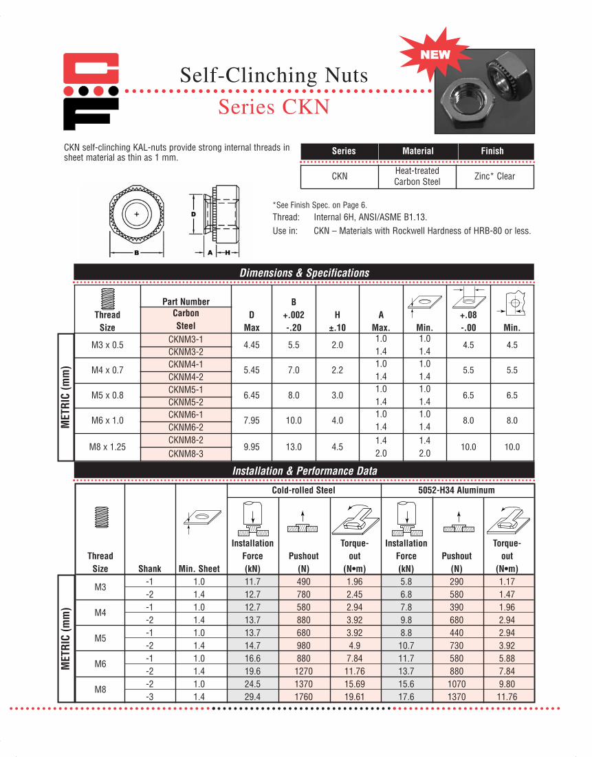
ThreadSize
Part NumberD
Max
B+.002-.20
H±.10
AMax. Min.
+.08-.00 Min.
CarbonSteel
M3 x 0.5 CKNM3-1 4.45 5.5 2.01.01.4
1.01.4
4.5 4.5CKNM3-2
M4 x 0.7CKNM4-1
5.45 7.0 2.21.01.4
1.01.4
5.5 5.5CKNM4-2
M5 x 0.8 CKNM5-1 6.45 8.0 3.01.01.4
1.01.4
6.5 6.5CKNM5-2
M6 x 1.0CKNM6-1
7.95 10.0 4.01.01.4
1.01.4
8.0 8.0CKNM6-2
M8 x 1.25CKNM8-2
9.95 13.0 4.51.42.0
1.42.0
10.0 10.0CKNM8-3
Dimensions & Specifications
CKN self-clinching KAL-nuts provide strong internal threads insheet material as thin as 1 mm.
*See Finish Spec. on Page 6.Thread: Internal 6H, ANSI/ASME B1.13.Use in: CKN – Materials with Rockwell Hardness of HRB-80 or less.
MET
RIC
(mm
)
Installation & Performance Data
MET
RIC
(mm
)
Cold-rolled Steel 5052-H34 Aluminum
Installation Torque- Installation Torque-Thread Force Pushout out Force Pushout out
Size Shank Min. Sheet (kN) (N) (N•m) (kN) (N) (N•m)
M3 -1 1.0 11.7 490 1.96 5.8 290 1.17-2 1.4 12.7 780 2.45 6.8 580 1.47
M4 -1 1.0 12.7 580 2.94 7.8 390 1.96-2 1.4 13.7 880 3.92 9.8 680 2.94
M5 -1 1.0 13.7 680 3.92 8.8 440 2.94-2 1.4 14.7 980 4.9 10.7 730 3.92
M6 -1 1.0 16.6 880 7.84 11.7 580 5.88-2 1.4 19.6 1270 11.76 13.7 880 7.84
M8 -2 1.0 24.5 1370 15.69 15.6 1070 9.80-3 1.4 29.4 1760 19.61 17.6 1370 11.76
Self-Clinching Nuts
Series CKN
Series Material Finish
CKN Heat-treatedCarbon Steel Zinc* Clear
071112 Captive_2011_Text_Catalog 12/5/12 8:19 AM Page 24

2011
Dimensions & Specifications
INCH
(in.
)M
ETRI
C (m
m)
CFL flush nuts offer the advantage of being completely flush withinthe sheet while providing load-bearing threads in materials tooductile to tap. All dimen-sions are identical toindustry standards.
Thread: Internal 2B, ANSI B1.1 (6H, ANSI/ASME B1.13M)Use in: Materials with Rockwell Hardness of B-70 or less.
Thread Part D +.003 in. (.08 mm) H BSize Number Max. Min. –.000 (.00) Nom. Max. Min.
#2-56 CFL256-1 .171 .061 .172 .1875 .060 .23CFL256-2 .091 .090
#4-40 CFL440-1 .171 .061 .172 .1875 .060 .23CFL440-2 .091 .090
#6-32 CFL632-1 .212 .061 .213 .25 .060 .27CFL632-2 .091 .090
#8-32 CFL832-1 .289 .061 .290 .3125 .060 .28CFL832-2 .091 .090
#10-24 CFL1024-1 .311 .061 .312 .3438 .060 .31CFL1024-2 .091 .090
#10-32 CFL1032-1 .311 .061 .312 .3438 .060 .31CFL1032-2 .091 .090CFL420-3 .126 .120
1/4-20 CFL420-4 .343 .156 .344 .375 .151 .34CFL420-5 .187 .182CFL428-3 .126 .120
1/4-28 CFL428-4 .343 .156 .344 .375 .151 .34CFL428-5 .187 .182
M2 x 0.4CFLM2-1 4.34 1.5 4.37 4.8 1.5 6.0CFLM2-2 2.3 2.3
M2.5 x 4.5CFLM2.5-1 4.34 1.5 4.37 4.8 1.5 6.0CFLM2.5-2 2.3 2.3
M3 x 0.5 CFLM3-1 4.34 1.5 4.37 4.8 1.5 6.0CFLM3-2 2.3 2.3
M3.5 x 0.6 CFLM3.5-1 5.35 1.5 5.4 6.4 1.5 6.5CFLM3.5-2 2.3 2.3
M4 x 0.7 CFLM4-1 7.34 1.5 7.37 7.9 1.5 7.2CFLM4-2 2.3 2.3
M5 x 0.8 CFLM5-1 7.87 1.5 7.92 8.7 1.5 8.0CFLM5-2 2.3 2.3CFLM6-3 3.2 3.1
M6 x 1.0 CFLM6-4 8.71 4.0 8.74 9.5 3.9 8.8CFLM6-5 4.75 4.7
B
D H
Clinching profile may vary.
Self-Clinching Flush Nuts
Series CFL
Series Material Finish
CFL 300 SeriesStainless Steel
PassivatedASTM A380
071112 Captive_2011_Text_Catalog 12/5/12 8:19 AM Page 25

Installation & Performance Data
INCH
(in.
)M
ETRI
C (m
m)
Cold-rolled Steel 5052-H34 Aluminum
Max.Screw Installation Installation
Part torque Force Pushout Force PushoutNumber (in.-lbs.) (tons) (lbs.) (tons) (lbs.)
CFL256-1 1.5 1.5 200 1 200CFL256-2 1.5 1.5 200 1 200CFL440-1 2.5 1.5 200 1 200CFL440-2 2.5 1.5 200 1 200CFL632-1 3.5 1.5 200 1 200CFL632-2 3.5 1.5 200 1 200CFL832-1 5.25 2 240 1 240CFL832-2 5.25 2 240 1 240CFL1024-1 7.5 2 240 1.5 240CFL1024-2 7.5 2 240 1.5 240CFL1032-1 7.5 2 240 1.5 240CFL1032-2 7.5 2 240 1.5 240
CFL420-3,4,5 35 2.25 840 1.75 640CFL428-3,4,5 35 2.25 840 1.75 640
Max.Screw Installation Installation
Part Torque Force Pushout Force PushoutNumber (N•m) (kN) (kN) (kN) (kN)CFLM2-1 .16 13.3 .9 8.9 .9CFLM2-2 .16 13.3 .9 8.9 .9
CFLM2.5-1 .23 13.3 .9 8.9 .9CFLM2.5-2 .23 13.3 .9 8.9 .9CFLM3-1,2 .3 13.3 .9 8.9 .9
CFLM3.5-1,2 .4 15 1.0 8.9 .9CFLM4-1,2 .5 17 1.1 8.9 1.0CFLM5-1,2 .8 17 1.1 11 1.1
CFLM6-3,4,5 3.7 20 3.7 15 2.8
Continued from previous page.
Self-Clinching Flush Nuts
Series CFL
071112 Captive_2011_Text_Catalog 12/5/12 8:19 AM Page 26
2011
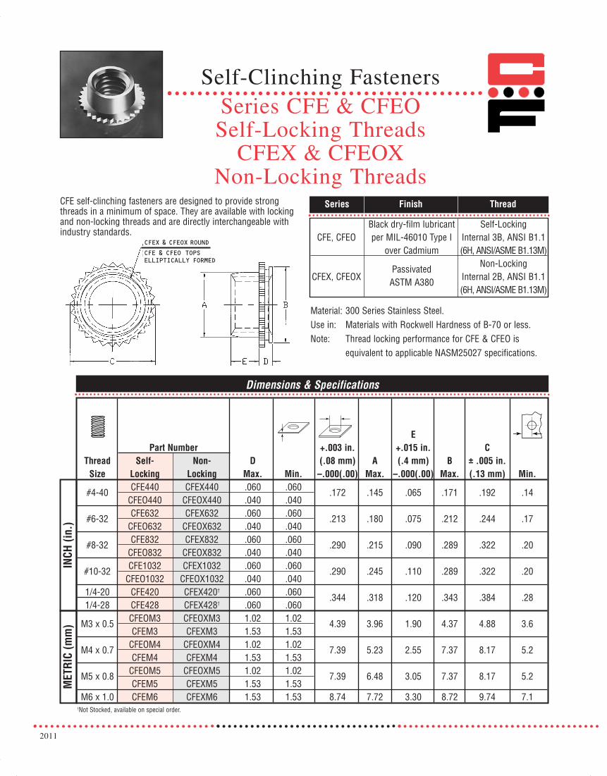
CFE self-clinching fasteners are designed to provide strongthreads in a minimum of space. They are available with lockingand non-locking threads and are directly interchangeable withindustry standards.
Series Finish Thread
Dimensions & Specifications
INCH
(in.
)M
ETRI
C (m
m)
Black dry-film lubricant Self-LockingCFE, CFEO per MIL-46010 Type I Internal 3B, ANSI B1.1
over Cadmium (6H, ANSI/ASME B1.13M)
Passivated Non-LockingCFEX, CFEOX ASTM A380 Internal 2B, ANSI B1.1
(6H, ANSI/ASME B1.13M)
Material: 300 Series Stainless Steel.Use in: Materials with Rockwell Hardness of B-70 or less.Note: Thread locking performance for CFE & CFEO is
equivalent to applicable NASM25027 specifications.
EPart Number +.003 in. +.015 in. C
Thread Self- Non- D (.08 mm) A (.4 mm) B ± .005 in.Size Locking Locking Max. Min. –.000(.00) Max. –.000(.00) Max. (.13 mm) Min.
#4-40 CFE440 CFEX440 .060 .060 .172 .145 .065 .171 .192 .14CFEO440 CFEOX440 .040 .040
#6-32 CFE632 CFEX632 .060 .060 .213 .180 .075 .212 .244 .17CFEO632 CFEOX632 .040 .040
#8-32 CFE832 CFEX832 .060 .060 .290 .215 .090 .289 .322 .20CFEO832 CFEOX832 .040 .040
#10-32 CFE1032 CFEX1032 .060 .060 .290 .245 .110 .289 .322 .20CFEO1032 CFEOX1032 .040 .040
1/4-20 CFE420 CFEX420† .060 .060 .344 .318 .120 .343 .384 .281/4-28 CFE428 CFEX428† .060 .060
M3 x 0.5 CFEOM3 CFEOXM3 1.02 1.02 4.39 3.96 1.90 4.37 4.88 3.6CFEM3 CFEXM3 1.53 1.53
M4 x 0.7 CFEOM4 CFEOXM4 1.02 1.02 7.39 5.23 2.55 7.37 8.17 5.2CFEM4 CFEXM4 1.53 1.53
M5 x 0.8 CFEOM5 CFEOXM5 1.02 1.02 7.39 6.48 3.05 7.37 8.17 5.2CFEM5 CFEXM5 1.53 1.53
M6 x 1.0 CFEM6 CFEXM6 1.53 1.53 8.74 7.72 3.30 8.72 9.74 7.1†Not Stocked, available on special order.
CFEX & CFEOX ROUND
CFE & CFED TOPSELLIPTICALLY FORMEDCFE & CFEO TOPSELLIPTICALLY FORMED
Self-Clinching FastenersSeries CFE & CFEOSelf-Locking Threads
CFEX & CFEOXNon-Locking Threads
071112 Captive_2011_Text_Catalog 12/5/12 8:19 AM Page 27

Installation & Performance Data
INCH
(in.
)M
ETRI
C (m
m)
Continued from previous page.
Cold-rolled Steel 5052-H34 Aluminum
Sheet Installation Torque- Installation Torque-Thread Thickness Force Pushout out Force Pushout out
Size Series (in.) (lbs.) (lbs.) (in.-lbs.) (lbs.) (lbs.) (in.-lbs.)
#4-40 CFEO, CFEOX .040 1500 135 10 900 85 10CFE, CFEX .060 1500 200 10 900 130 10
#6-32 CFEO, CFEOX .040 2100 180 20 1200 100 20CFE, CFEX .060 2100 250 20 1300 170 20
#8-32 CFEO, CFEOX .040 2500 250 47 1500 150 47CFE, CFEX .060 2500 350 47 1500 250 47
#10-32 CFEO, CFEOX .040 2500 250 47 1500 150 47CFE, CFEX .060 2500 350 47 1500 250 47
1/4-20 CFE, CFEX .060 3500 400 105 2100 300 1051/4-28
Cold-rolled Steel 5052-H34 Aluminum
Sheet Installation Torque- Installation Torque-Thread Thickness Force Pushout out Force Pushout out
Size Series (mm.) (kN) (N) (N•m) (kN) (N) (N•m)
M3 CFEO, CFEOX 1.0 6.7 600 1.3 4.0 380 1.3CFE, CFEX 1.5 6.7 900 1.3 4.0 590 1.3
M4 CFEO, CFEOX 1.0 11.1 1100 5.3 7.0 675 5.3CFE, CFEX 1.5 11.1 1600 5.3 7.0 1100 5.3
M5 CFEO, CFEOX 1.0 12 1200 5.3 7.0 675 5.3CFE, CFEX 1.5 12 1600 5.3 7.0 1100 5.3
M6 CFE, CFEX 1.5 15.6 1800 11.3 9.0 1400 11.3
Self-Clinching FastenersSeries CFE & CFEOSelf-Locking Threads
CFEX & CFEOXNon-Locking Threads
071112 Captive_2011_Text_Catalog 12/5/12 8:19 AM Page 28

Dimensions & Specifications
Series
Thread Size
Carbon Steel
StainlessSteel
Aluminum† ShankCode
A Max. Min.
+.003 -.000
B Max.
D Max.
C ±.010
H Nom.
1 .038 .040 #440 CRT CRTS CRTA
2 .054 .056 .187 .186 .185 .135 .250 .156
1 .038 .040 #6-32 CRT CRTS CRTA
2 .054 .056 .219 .218 .220 .145 .312 .187
1 .038 .040 #8-32 CRT CRTS CRTA
2 .054 .056 .266 .265 .250 .175 .343 .203
1 .038 .040
INCH
(in.
)
#10-32 CRT CRTS CRTA 2 .054 .056
.312 .311 .285 .205 .375 .218
Dimensions & Specifications
Thread Size
Carbon Steel
StainlessSteel
Aluminum† ShankCode
A Max. Min.
+.08 -.00
B Max.
D Max.
C ±.25
H Nom.
1 .97 1.0 M3 x 0.5 CRT CRTS CRTA
2 1.38 1.4 4.75 4.73 4.85 3.43 6.35 4
1 .97 1.0 M4 x 0.7 CRT CRTS CRTA 2 1.38 1.4
6.76 6.73 6.2 4.45 8.73 5.2
1 .97 1.0
MET
RIC
(mm
)
M5 x 0.8 CRT CRTS CRTA 2 1.38 1.4
7.92 7.9 7.4 5.21 9.53 5.6
Part Number Structure: CRTS 440-1ML
ROHS CompliantShank Code Thread CodeSeries
Series
Min.
Min.
2011
Self-Clinching Self-LockingNuts
Series CRT, CRTS, CRTA
Series Material Finish
CRT Carbon Steel Black Dry film Lubricantover Zinc Phosphate
CRTS 300 SeriesStainless Steel
Black Dry filmLubricant
CRTA 7075-T6 Aluminum None
CRT series fasteners provide a low-installed-cost solutionwhere a clinching fastener with repeat locking torque is required.The design allows for greater reusability and minimizes thepossibility of thread damage of the mating screw.
Thread: Internal 3B, ANSI B1.1 (6H ANSI/ASME B1.13M).Use in: Cold-rolled Steel.
Note: Thread locking performance for CRT & CRTS isequivalent to applicable NASM25027 specifications.
071112 Captive_2011_Text_Catalog 12/5/12 8:19 AM Page 29

Installation & Performance Data
Cold-rolled Steel
Thread Size
Shank Code
Installation Force Pushout
(lbs.)Torque-out
(in.-lbs.)
Installation Force Pushout
(lbs.)Torque-out
(in.-lbs.)
1 3000 1600#4-40 2 3000 2000
1 4000 2400#6-32 2 4300 2700
1 4000 2700#8-32 2 4300 3000
1 4000 3200
INCH
(in.
)
#10-32 2 4300 3200
Thread Size
Shank Code
Installation Force (kN)
Pushout (N)
Torque-out (N•m)
Installation Force (kN)
Pushout (N)
Torque-out (N•m)
1 13.5 7M3 2 13.5 9
1 18 12M4 2 18 12
1 18 12
MET
RIC
(mm
)
M5 2 19 12
Continued from previous page.
Installation & Performance Data
155 31 134 26 258 41 207 36 155 46 134 26 284 51 232 46 196 51 155 46 310 72 258 52 258 103 155 93 310 124 258 108
688 3.5 598 2.9 1148 4.6 921 4.0 874 5.8 688 5.1 1376 8.1 1148 5.8 1148 11.6 688 10.4 1376 14.0 1148 12.2
5052-H34 Aluminum
Cold-rolled Steel 5052-H34 Aluminum
(lbs.)(lbs.)
Series CRT, CRTS & CRTA
Self-Clinching Self-LockingNuts
071112 Captive_2011_Text_Catalog 12/5/12 8:19 AM Page 30

2011
Thread: Internal 2B, ANSI B1.1 (6H, ANSI/ASME B1.13M).Use in: Material with Rockwell Hardness of B-70 or less.
Note 1. Installation TipsThin Sheets: May be installed in panel thickness of .040
to .059 in. (1mm to 1.5mm) if fastener ispartially installed in sheet. The knurled collarmust be raised above sheet by the difference in thickness from .059 in. (1.5mm).
Thick Sheets: If fastener is installed in sheet greater than .070in. (1.7mm), knurled collar may crack if mating screw is tightened above maximumtorque limit.
Note 2. Thread locking performance for CPL & CPLC isequivalent to applicable NASM25027 specifications.
Series Material Finish Locking Element
Dimensions & Specifications
INCH
(in.
)M
ETRI
C (m
m)
CPL Heat-treated Zinc* Clear Clear NylonCarbon Steel
CPLC 300 Series Passivated Clear NylonStainless Steel ASTM A380
+.003 in.Thread Part Number Thickness (.08mm) A B C D
Size Carbon Steel Stainless Steel Range –.000(.00) Max. Max. Max. Max. Min.#4-40 CPL440 CPLC440 .059-.070 .234 .233 .274 .130 .216 .132#6-32 CPL632 CPLC632 .059-.070 .265 .264 .305 .130 .246 .158#8-32 CPL832 CPLC832 .059-.070 .297 .296 .338 .155 .278 .184#10-32 CPL1032 CPLC1032 .059-.070 .312 .311 .353 .165 .292 .210
M3 x 0.5 CPLM3 CPLCM3 1.5-1.78 6.0 5.97 7.01 3.6 5.5 4.3M4 x 0.7 CPLM4 CPLCM4 1.5-1.78 7.5 7.47 8.54 4.2 7.0 5.6M5 x 0.8 CPLM5 CPLCM5 1.5-1.78 8.0 7.97 9.0 4.5 7.5 6.4
B
D
A
C
.060 In. (1.5 mm) MAX.
CLEAR NYLONLOCKING ELEMENT
CPL top collar lock nuts combine reliable self-clinching mountingwith a reusable non-metallic thread locking element.
*See Finish Spec. on Page 6.
See Note 1
Self-ClinchingTop Collar Lock Nuts
Series CPL & CPLC
071112 Captive_2011_Text_Catalog 12/5/12 8:19 AM Page 31

Installation & Performance Data
Continued from previous page.
.048 in. Cold-rolled Steel .060 in. Cold-rolled Steel
Max.Tightening Installation Torque- Installation Torque-
Thread Torque Force Pushout out Force Pushout outSize (in.-lbs.) (tons) (lbs.) (in.-lbs.) (tons) (lbs.) (in.-lbs.)
#4-40 9 1-2 230 20 1-2 260 20#6-32 12 1-2 270 30 1-2 290 30#8-32 19 1-2 270 60 1-2 290 60#10-32 26 1-2 300 70 1-2 350 70
.060 in. 5052H34 Aluminum .040 in. 5052H34 AluminumMax.
Tightening Installation Torque- Installation Torque-Thread Torque Force Pushout out Force Pushout out
Size (in.-lbs.) (tons) (lbs.) (in.-lbs.) (tons) (lbs.) (in.-lbs.)#4-40 9 1 225 20 1 150 20#6-32 12 1 285 30 1 180 25#8-32 19 1 290 60 1 180 28#10-32 26 1 300 70 1 180 40
1.5mm Cold-rolled Steel 1.2mm Cold-rolled SteelMax.
Tightening Installation Torque- Installation Torque-Thread Torque Force Pushout out Force Pushout out
Size (N•m) (kN) (N) (N•m) (kN) (N) (N•m)M3 1.1 13.34 1156 2.2 13.34 1000 2.2M4 2.2 13.34 1290 6.7 13.34 1200 6.7M5 3.1 13.34 1557 7.9 13.34 1380 7.9
1.5mm 5052H34 Aluminum 1.0mm 5052H34 AluminumMax.
Tightening Installation Torque- Installation Torque-Thread Torque Force Pushout out Force Pushout out
Size (N•m) (kN) (N) (N•m) (kN) (N) (N•m)M3 1.1 8.90 1000 2.2 6.67 710 2.2M4 2.2 8.90 1290 6.7 6.67 800 3.1M5 3.1 8.90 1330 7.9 6.67 800 4.5
INCH
(in.
)M
ETRI
C (m
m)
Self-ClinchingTop Collar Lock Nuts
Series CPL & CPLC
071112 Captive_2011_Text_Catalog 12/5/12 8:19 AM Page 32

2011
CH studs provide a strong flush-head assembly in material as thin as .040 in. (1.0 mm) with high torque-out and pushout performance.
CH Heat-treated Zinc* ClearCarbon Steel
CHS 300 Series PassivatedStainless Steel ASTM A380
CHA 2024-T4 NoneAluminum
Series Material Finish
Dimensions & Specifications
INCH
(in.
)
Thread: External 2A, ANSI B1.1 (6g ANSI/ASME B1.13M).**Use in: CH- Materials with HRB-80 or less.
CHS- Materials with HRB-70 or less.CHA- Materials with HRB-50 or less.
**See Note 3 on Page 6 for Gauging Spec.
Max.††
Rec. NutL Tight.
Thread Thread Length ±.015 in. D +.003 TorqueSize Code .250 .3125 .375 .500 .625 .750 .875 1.00 1.25 1.50 ± .015 –.000 in.-lbs. Min. Min.
#2-56 256 -4 -5 -6 -8 -10 -12† .144 .085 2.5 .187 .040#4-40 440 -4 -5 -6 -8 -10 -12 -14 -16† .176 .111 5 .219 .040#6-32 632 -4 -5 -6 -8 -10 -12 -14 -16 -20 -24† .206 .137 10 .250 .040#8-32 832 -4 -5 -6 -8 -10 -12 -14 -16 -20 -24† .237 .163 15 .281 .040#10-24 1024 -5† -6 -8 -10 -12 -14 -16 -20 -24† .256 .189 25 .281 .040#10-32 1032 -5† -6 -8 -10 -12 -14 -16 -20 -24 .256 .189 30 .281 .0401/4-20 420 -6 -8 -10 -12 -14 -16 -20 -24 .337 .249 55 .312 .062
5/16-18 518 -8 -10 -12 -14 -16 -20 -24 .376 .311 115 .375 .093
Continued on next page.
L D
Dimensions & Specifications
† Not stocked, available on special order. †† For aluminum studs, values are 60% of those listed.
*See Finish Spec. on Page 6.Part Number Structure:CH 256-4
Length CodeThread CodeSeries
Note: Studs are available in lengths up to 3 in. (76.2 mm) upon special order for 1/4-20/M6 and larger.
MET
RIC
(mm
)
Max.††
Rec. NutTight.TorqueN•m
LThread Thread Length ± .4 mm D +.08
Size Code 6 8 10 12 15 18 20 22 25 28 30 35 38 ± .4 –.00 Min. Min.M2.5x0.45 M2.5 -6† -8† -10† -12† -15† -18† 4.1 2.5 .40 5.4 1.0
M3x0.5 M3 -6† -8 -10 -12 -15 -18 -20 -22 -25 4.6 3.0 .72 5.6 1.0M3.5x0.6 M3.5 -6 -8 -10 -12 -15 -18 -20 -22 -25 -28 -30 5.3 3.5 1.1 6.4 1.0M4x0.7 M4 -6† -8 -10 -12 -15 -18 -20 -22 -25 -28 -30 -35 -38 5.9 4.0 1.6 7.2 1.0M5x0.8 M5 -8† -10 -12 -15 -18 -20 -22 -25 -28 -30 -35 -38 6.5 5.0 3.4 7.2 1.0M6x1.0 M6 -10 -12 -15 -18 -20 -22 -25 -28 -30 -35 -38 8.2 6.0 5.7 7.9 1.6M8x1.25 M8 -12* -15 -18 -20 -22 -25 -28 -30 -35 -38 9.6 8.0 14.0 9.6 2.4
Self-Clinching Studs
Series CH, CHS & CHA
071112 Captive_2011_Text_Catalog 12/5/12 8:19 AM Page 33

MET
RIC
(mm
)
INCH
(in.
)
Continued from previous page.
Thread Anvil Dimensions (in.)Code X +.004 Y +.003
256 .110 .087.114 .090
440 .136 .113.140 .116
632 .162 .139.166 .142
832 .188 .165.192 .168
1024 .216 .191.220 .194
1032 .216 .191.220 .194
420 .295 .250.300 .253
518 –– .3125–– .3155
Anvil Dimensions (mm)Thread X YCode +.1 +.08M2.5 3.1 2.50M3 3.6 3.00
M3.5 4.1 3.50M4 4.6 4.00M5 5.6 5.00M6 6.6 6.00M8 –– 8.00
Tooling for sheet thickness .059 in. (1.51mm) and less with #2 (M2.5) thru#10 (M5) thread sizes and less than .093 in. (2.3mm) for 1/4 in. (M6) threads.
Tooling for sheet thickness .060 in. (1.51mm) minimum and greater with #2 (M2.5) thru #10 (M5) thread sizes and .092 in. (2.3mm) minimum and greater for 1/4 in. (M6) and 5/16 in. (M8) threads.
PRESS
SHEET
ASSEMBLYANVIL
STUD
45˚
LENGTHOF STUD+.125 in. (3.175mm)
X
Y
ASSEMBLYANVIL
STUD
LENGTHOF STUD+.125 in. (3.175mm)
YPRESS
SHEET
TOOLING
Note 1.For material thickness of .059 in. or less, a countersunkhole is needed in the anvil.
Note 2.For material thickness of .060 in. or more, a through-holeis needed in the anvil.
Self-Clinching Studs
Series CH, CHS & CHA
071112 Captive_2011_Text_Catalog 12/5/12 8:19 AM Page 34

2011
Sheet Installation Torque-Thread Thickness & Force Pushout outCode Material (lbs.) (lbs.) (in.-lbs.)
256 .062 Aluminum 2000 95 5.060 Steel 2500 175 5
440 .064 Aluminum 3800 165 10.060 Steel 4300 270 10
632 .064 Aluminum 3800 175 19.060 Steel 4700 295 19
832 .064 Aluminum 4800 215 29.060 Steel 6800 370 39
1024 .064 Aluminum 5500 265 371032 .060 Steel 6800 445 59
420 .093 Aluminum 6500 305 64.088 Steel 9500 570 95
518 .093 Aluminum 6500 425 105.093 Steel 10000 645 170
Sheet Installation Torque-Thread Thickness & Force Pushout outCode Material (kN) (N) (N•m)
M2.5 1.6 Aluminum 8.9 465 .91.5 Steel 11.1 740 .9
M3 1.6 Aluminum 12.9 600 1.61.5 Steel 14.7 820 1.6
M3.5 1.6 Aluminum 15.6 800 1.61.5 Steel 22.3 1335 2.7
M4 1.6 Aluminum 20.0 975 2.81.5 Steel 28.9 1780 4.1
M5 1.6 Aluminum 24.5 1070 3.41.5 Steel 33.4 1980 6.4
M6 2.4 Aluminum 44.5 1660 7.22.2 Steel 42.3 2560 11.2
M8 2.4 Aluminum 29.8 1910 11.22.2 Steel 44.5 2890 19.1
Installation & Performance Data
INCH
(in.
)M
ETRI
C (m
m)
Continued from previous page.
Note: Values based on stainless steel studs (steel stud values may be higher).Note: Values based on stainless steel studs (steel stud values may be higher).
Self-Clinching Studs
Series CH, CHS & CHA
071112 Captive_2011_Text_Catalog 12/5/12 8:19 AM Page 35

HCH high-torque studs offer advantages over weld studs andother fasteners. The heavy head configuration provides greatertorque-out and improved pull-through resistance.Phospher Bronze studs provide excellent electrical conductivityand mechanical attachment in copper.
Series Material Finish
HCH Heat-treated Zinc* ClearMedium Carbon Steel
HCHS 300 Series PassivatedStainless Steel ASTM A380
HCHB Phosphor Bronze NoneCDA-510
Thread: External 2A, ANSI B1.1 (6g ANSI/ASME B1.13M).**Use in: Cold-rolled Steel or 5052-H34 Aluminum with
Rockwell Hardness as follows:
Dimensions & Specifications
Max.L Hole in
Thread Thread Length ± .015 in. +.005 Attach. A BSize Code .500 .750 1.00 1.25 1.50 1.75 Min. –.000 Parts Max. ± .01 Min.
#10-24 1024 -8 -12 -16 -20 -24 -28 .050 .190 .250 .040 .300 .415#10-32 1032 -8 -12 -16 -20 -24 -28† .050 .190 .250 .040 .300 .4151/4-20 420 -8 -12 -16 -20 -24 -28† .060 .250 .312 .050 .380 .4605/16-18 518 -8† -12 -16 -20 -24 -28† .075 .312 .375 .070 .480 .5003/8-16 616 -12 -16 -20 -24 -28† .090 .375 .437 .085 .580 .530
Dimensions & Specifications
B
A L
Max.L Hole In
Thread Thread Length ± .4 mm +.13 Attach. A BSize Code 20 25 30 35 40 50 Min. –.00 Parts Max. ± .25 Min.
M5x0.8 M5 -20 -25 -30 1.3 5.0 6.5 1.14 7.8 10.7M6x1.0 M6 -20 -25 -30 -35 1.5 6.0 7.5 1.27 9.4 11.5M8x1.25 M8 -20 -25 -30 -35 -40 -50 2.0 8.0 9.5 1.78 12.5 12.7M10x1.5 M10 -20 -25 -30 -35 -40 -50 2.3 10.0 11.5 2.29 15.7 13.7
Thread Strength: HCH = 120 ksi / HCHS = 75 ksi / HCHB = 60 ksi.† Not stocked, available on special order.
INCH
(in.
)M
ETRI
C (m
m)
*See Finish Spec. on Page 6.
HCH 1024-8Length CodeThread CodeSeries
Thread Strength: HCH = 900 MPa / HCHS = 515 MPa / HCHB = 415 MPa.Note: Studs are available in lengths up to 3 in. (76.2 mm) upon special order for 1/4-20/M6 and larger.
HCH- Materials with HRB-85 or less.HCHS- Materials with HRB-70 or less.HCHB- Materials with HRB-55 or less.
**See Note 3 on Page 6 for Gauging Spec.
Part Number Structure:
The head of the studwill remain above thesurface when properlyinstalled.
Self-Clinching Studs
Series HCH, HCHS & HCHB(High-Torque)
071112 Captive_2011_Text_Catalog 12/5/12 8:19 AM Page 36

2011
Installation & Performance Data
INCH
(in.
)
Continued from previous page.
Self-Clinching Studs
Series HCH, HCHS & HCHB(High-Torque)
ThreadCode Series
Sheet Thickness &Material
SheetHardness
HRBInstallationForce (lbs.)
Pushout(lbs.)
Torque-out (ft.-lbs.)
Max. NutTightening
Torque (ft.-lbs.)
10241032
HCH .060 Aluminum 15 3000 175 4 3.25HCH .060 Steel 65 6000 370 5.5 3.25
HCHS .050 Aluminum 38 3000 175 4 3.25HCHS .058 Aluminum 52 4500 320 4 3.25HCHB .061 Copper CDA-110 28 3400 145 2.9 2.56
420
HCH .060 Aluminum 43 5500 280 11 8HCH .060 Steel 59 7000 475 11 8
HCHS .064 Aluminum 32 4000 280 8 8HCHS .072 Aluminum 43 6500 475 8 8HCHB .061 Copper CDA-110 28 6000 375 5 4.35
518
HCH .091 Aluminum 39 8000 375 22 16HCH .090 Steel 58 10000 585 22 16
HCHS .087 Aluminum 41 5500 375 15 16HCHS .099 Steel 44 7500 585 15 16HCHB .126 Copper CDA-110 32 7500 495 11 10.56
616
HCH .091 Aluminum 39 12000 545 25 27HCH .090 Steel 58 18000 775 36 27
HCHS .123 Aluminum 44 10000 555 25 27HCHS .099 Steel 44 13000 775 25 27HCHB .126 Copper CDA-110 32 12000 555 18 21
MET
RIC
(mm
)
ThreadCode Series
Sheet Thickness &Material
SheetHardness
HRBInstallationForce (kN) Pushout (N)
Torque-out (N • m)
Max. NutTightening
Torque (N • m)
M5
HCH 1.5 Aluminum 15 13 795 5.4 4.4HCH 1.5 Steel 65 26 1495 7.6 4.4
HCHS 1.62 Aluminum 35 12.4 795 5.4 4.4HCHS 1.47 Aluminum 54 21.7 1495 6.4 4.4HCHB 1.5 Copper CDA-110 28 15.6 1110 3.4 3.47
M6
HCH 1.5 Aluminum 43 29 1265 14 10HCH 1.5 Steel 59 33 1745 14 10
HCHS 1.62 Aluminum 35 15.4 1265 11 10HCHS 1.6 Aluminum 45 24.6 1745 11 10HCHB 1.5 Copper CDA-110 28 25.3 1595 6.7 5.9
M8
HCH 2.3 Aluminum 39 35.6 1695 30 21.7HCH 2.3 Steel 58 44.5 2195 30 21.7
HCHS 2.23 Aluminum 44 24.4 1695 20 21.7HCHS 2.48 Steel 43 37.8 2095 20 21.7HCHB 3.2 Copper CDA-110 32 33 2245 15.3 14.3
M10
HCH 2.3 Aluminum 39 53.3 2440 36 36.6HCH 2.3 Steel 58 80 3465 49 36.6
HCHS 2.3 Aluminum 44 44.4 2440 36 36.6HCHS 2.3 Steel 44 57.7 3465 36 36.6HCHB 3.2 Copper CDA-110 32 53.3 2495 25 28.5
071112 Captive_2011_Text_Catalog 12/5/12 8:19 AM Page 37
Self-Clinching Studs
Series HCW(Wide-Head)
ThreadSize
ThreadCode
LLength ± .015 in.
Min. SheetThickness
+.005-.000
AMax.
B± .01
Max Holein
AttachedParts Min..500 .750 1.00 1.25 1.50 1.75 2.00
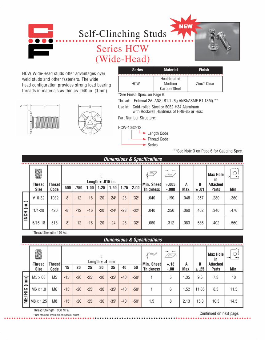
#10-32 1032 -8† -12 -16 -20 -24† -28† -32† .040 .190 .048 .357 .280 .360
1/4-20 420 -8† -12 -16 -20 -24† -28† -32† .040 .250 .060 .462 .340 .470
5/16-18 518 -8† -12 -16 -20 -24 -28† -32† .060 .312 .083 .586 .402 .560
ThreadSize
ThreadCode
LLength ± .4 mm Min. Sheet
Thickness+.13-.00
AMax.
B± .25
Max Holein
AttachedParts Min.15 20 25 30 35 40 50
M5 x 08 M5 -15† -20 -25† -30 -35† -40† -50† 1 5 1.35 9.6 7.3 10
M6 x 1.0 M6 -15† -20 -25† -30 -35† -40† -50† 1 6 1.52 11.35 8.3 11.5
M8 x 1.25 M8 -15† -20 -25† -30 -35† -40† -50† 1.5 8 2.13 15.3 10.3 14.5
Thread Strength= 900 MPa.† Not stocked, available on special order.
Thread Strength= 120 ksi.
INCH
(in.
)M
ETRI
C (m
m)
Dimensions & Specifications
Dimensions & Specifications
Continued on next page.
**See Note 3 on Page 6 for Gauging Spec.
HCW Wide-Head studs offer advantages overweld studs and other fasteners. The widehead configuration provides strong load bearingthreads in materials as thin as .040 in. (1mm).
Series Material Finish
*See Finish Spec. on Page 6.Thread: External 2A, ANSI B1.1 (6g ANSI/ASME B1.13M).**Use in: Cold-rolled Steel or 5052-H34 Aluminum
with Rockwell Hardness of HRB-85 or less:
HCW-1032-12Length CodeThread CodeSeries
Part Number Structure:
HCWHeat-treated
MediumCarbon Steel
Zinc* Clear
071112 Captive_2011_Text_Catalog 12/5/12 8:19 AM Page 38

2011
Installation & Performance Data
Thread Code Sheet Thickness & Material Sheet Hardness
HRB Installation Force
(lbs.) Pushout
(lbs.) Torque-out (in.-lbs.)
1032
420
INCH
(in.
)
518
Thread Code Sheet Thickness & Material Sheet Hardness
HRB Installation Force
(kN) Pushout
(N) Torque-out
(N•m)
M5
M6 MET
RIC
(mm
)
M8
Continued from previous page.
58
58
118
128
238
288
165
295
175
335
270
570
7500
9500
8000
13500
9000
15500
27
67
27
67
22
65
.040 Aluminum
.040 Cold Rolled Steel
.040 Aluminum
.040 Cold Rolled Steel
.060 Aluminum
.060 Cold Rolled Steel
8.0
8.0
11.7
14.3
23.4
33.8
685
1345
745
1395
1225
2395
37.7
51.1
39
60
42
71.1
27
67
27
67
22
65
1 mm Aluminum
1 mm Cold Rolled Steel
1 mm Aluminum
1 mm Cold Rolled Steel
1.5 mm Aluminum
1.5 mm Cold Rolled Steel
Self-Clinching Studs
Series HCW(Wide-Head)
CAPTIVE studs are available with a dog-point end to assist theattachment of mating nuts, which is especially useful in high-speed production assembly, using motorized nut drivers. Dog-points may be specified on most CH, TCH, HCH, CHTS, andHCW style studs as a special order, using the following PartNumber Structure:
HCW 1032-8 DPDog-PointLength CodeThread CodeSeries
CAPTIVE® Dog-Point Studs
Note: Maximum dog-point diameter is .003 in. (.08 mm) less than the minimum minor diameter of 2B or 6g mating nut threads.
INCH D P METRIC D P(in.) ±.005 ±.010 (mm) ±.13 ±.256-32 .086 .050 M3.5 x 0.6 2.4 1.278-32 .111 .055 M4 x 0.7 2.79 1.410-24 .124 .065 M5 x 0.8 3.66 1.7810-32 .138 .065 M6 x 1 4.37 2.03
1/4 x 20 .173 .085 M8 x 1.25 6.05 2.671/4 x 28 .192 .0855/16 x 18 .228 .105
Example:
P
D
071112 Captive_2011_Text_Catalog 12/5/12 8:20 AM Page 39

TCH non-flush studs are manufactured for use in sheets as thin as .020 inches (.5 mm) thick. The pushout and torque-outvalues are excellent for most applications. The head of the studwill project above the panel surface when installed properly. Do not over squeeze!
TCH Heat-treated Zinc* ClearCarbon Steel
TCHS 300 Series PassivatedStainless Steel ASTM A380
Series Material Finish
Thread: External 2A, ANSI B1.1 (6g ANSI/ASME B1.13M).**Use in: Cold-rolled Steel or 5052-H34 Aluminum with
Rockwell Hardness as follows:
A L
B
Dimensions & Specifications
LThread Thread Length ± .015 in. +.003 A B
Size Code .250 .3125 .375 .500 .625 .750 .875 1.00 1.25 1.50 Min. –.000 Max. ± .015 Min.#4-40 440 -4 -5 -6 -8 -10 -12 .020 .111 .025 .176 .219#6-32 632 -4 -5 -6 -8 -10 -12 -14 -16 -20 -24† .020 .137 .025 .203 .250#8-32 832 -4 -5 -6 -8 -10 -12 -14 -16 -20 -24† .020 .163 .025 .234 .281#10-24 1024 -5† -6 -8 -10 -12 -14 -16 -20 -24† .020 .189 .025 .250 .281#10-32 1032 -5† -6 -8 -10 -12 -14 -16 -20 -24† .020 .189 .025 .250 .281
INCH
(in.
)M
ETRI
C (m
m)
†Not stocked, available on special order.
Dimensions & Specifications
LThread Thread Length ± .4 mm +.08 A B
Size Code 6 8 10 12 15 18 20 22 25 28 30 35 38 Min. -.00 Max. ± .4 Min.M3 x 0.5 M3 -6 -8 -10 -12 -15 -18 .51 3.0 .64 4.5 5.6M4 x 0.7 M4 -10 -12 -15 -18 -20 -22 -25 -28 -30 -35 -38 .51 4.0 .64 5.8 7.2M5 x 0.8 M5 -10 -12 -15 -18 -20 -22 -25 -28 -30 -35 -38 .51 5.0 .64 6.4 7.2
TCH - Materials with HRB 80 or less.TCHS - Materials with HRB 70 or less.
**See Note 3 on Page 6 for Gauging Spec.
*See Finish Spec. on Page 6.
TCH 440-4Length CodeThread CodeSeries
Part Number Structure:
Self-Clinching StudsSeries TCH & TCHS
Non-Flush Studs
071112 Captive_2011_Text_Catalog 12/5/12 8:20 AM Page 40

2011
Continued from previous page.
Installation & Performance Data
INCH
(in.
)M
ETRI
C (m
m)
Max. NutTight. Sheet Sheet Installation
Thread Torque Thickness & Hardness Force Pushout Torque-outCode (in-lbs.) Material HRB (lbs.) (lbs.) (in.-lbs.)
440 5 .020 Aluminum 28 1200 40 6.9.025 Steel 52 1500 95 7.8
632 9 .020 Aluminum 28 1500 45 7.9.025 Steel 52 2500 105 15.8
832 17 .020 Aluminum 28 2100 55 9.8.025 Steel 52 2700 115 25.7
1024 24 .020 Aluminum 28 2500 60 13.81032 27 .025 Steel 52 3000 135 27.7
Max. NutTight. Sheet Sheet Installation
Thread Torque Thickness & Hardness Force Pushout Torque-outCode (N•m) Material HRB (kN) (N) (N•m)
M3 .74 .5 Aluminum 28 5.3 190 .6.6 Steel 52 6.7 290 1.0
M4 1.70 .5 Aluminum 28 9.8 245 .7.6 Steel 52 13.4 495 2.5
M5 3.50 .5 Aluminum 28 13.4 265 1.2.6 Steel 52 17.8 665 2.9
Note: Values based on stainless steel studs (steel stud values may be higher).
Self-Clinching StudsSeries TCH & TCHS
Non-Flush Studs
071112 Captive_2011_Text_Catalog 12/5/12 8:20 AM Page 41

MET
RIC
(mm
)
Length CodeThread CodeSeries
Part Number Structure:
CHE 256 -4
Thread:
Use in : CHE – Materi als with HRB-80 or less.CHES – Materials with HRB-70 or less.
L D
U
*See Finish Spec. on Page 6.
Note: Min Sheet Thickness 1 mm.
Note: Min Sheet Thickness .040 in.
-6 -8 -10 -12 -15 -18
-6 -8 -10 -12 -15 -18 -20 -25
-6 -8 -10 -12 -15 -18 -20 -25 -30
-6 -8 -10 -12 -15 -18 -20 -25 -30 -35
-8 -10 -12 -15 -18 -20 -25 -30 -35
2.5 3.15 2.1 2.8
3 3.65 2.1 3.3
3.5 4.15 2.3 3.8
4 4.65 2.4 4.3
5 5.9 2.7 5.6
M2.5 x 0.45 CHE CHES M2.5
M3 x 0.5 CHE CHES M3
M3.5 x 0.6 CHE CHES M3.5
M4 x 0.7 CHE CHES M4
M5 x 0.8 CHE CHES M5
-4 -5 -6 -8 -10 -12
-4 -5 -6 -8 -10 -12 -14 -16
-4 -5 -6 -8 -10 -12 -14 -16 -20 -24
-4 -5 -6 -8 -10 -12 -14 -16 -20 -24
-5 -6 -8 -10 -12 -14 -16 -20 -24
.085 .112 .080 .098
.111 .138 .085 .124
.137 .164 .090 .150
.163 .190 .090 .176
.189 .225 .100 .210
#2-56 CHE CHES 256
#4-40 CHE CHES 440
#6-32 CHE CHES 632
#8-32 CHE CHES 832
#10-32 CHE CHES 1032
L Length ± .015 in.
Thread Size
Thread Code .250 .312 .375 .500 .625 .750 .875 1.00 1.25 1.50 Min.
Series
D±.015
U Max.
+.003-.000SSSteel
L Length ± .4 mm
Thread Size
Thread Code
Series
SSSteel 6 8 10 12 15 18 20 25 30 35+.08-.00 Min.
D± .4 Max.
U
Dimensions & Specifications
Dimensions & Specifications
INCH
(in
.)
CHE Heat-treated Zinc* ClearCarbon Steel
CHES 300 Series PassivatedStainless Steel ASTM A380
Series Material Finish
External 2A, ANSI B1.1 (6g ANSI/ASME B1.13M).**
**See Note 3 on Page 6 for Gauging Spec.
Close Edge Studs
Series CHE & CHES
CHE studs allow installation closer to material edge thanstandard studs without distortion of sheet edge. Provides flush-head assembly in material thickness of .040 in. (1 mm) ormore.
071112 Captive_2011_Text_Catalog 12/5/12 8:20 AM Page 42

2011
Installation Procedure1) Prepare the correct size hole in the base material by punching or drilling. Do not deburr hole.2) Place the stud through the hole in the base material and insert into the support anvil.3) Apply sufficient squeezing force with a shop press until the head of the fastener is flush with the sheet material.
Anvil Dimensions (in)SERIESX +.004 Y + .003
256 .110 .087 M2.5 3.1 2.53440 .136 .113 M3 3.6 3.03632 .162 .139 M3.5 4.1 3.53832 .188 .165 M4 4.6 4.03IN
CH (in
.)
1032 .216 .191 M5 5.6 5.03
X
Y
ASSEMBLY ANVIL
LENGTH OF STUD
+.125 in. (3.18 mm)
LENGTH OF STUD
+.125 in. (3.18 mm)
SHEET
ASSEMBLY ANVIL
PRESS STUD
Y
SHEET
PRESS STUD
45°
Anvil Dimensions (mm)SERIESX +.01 Y + .08
MET
RIC
(mm
)
Tooling for panel thickness.059 in. (1.5 mm) and less.
Tooling for panel thickness.060 in. (1.51 mm) and greater.
Continued from previous page.
Close Edge Studs
Series CHE & CHES
071112 Captive_2011_Text_Catalog 12/5/12 8:20 AM Page 43

Continued from previous page.
Close Edge Studs
Series CHE & CHES
Installation & Performance Data
INCH
(in.
) ThreadCode
Max. NutTightening
Torque(in. lbs.)
Sheet ThicknessAnd
Material
SheetHardness
HRB
InstallationForce(lbs.)
Pushout(lbs.)
TorqueOut
(in.-lbs.)
PullThru(lbs.)
TestBushing
HoleSize
256 2.3 .047 Aluminum 33 700 55 4 230 .1062.3 .045 Cold Rolled Steel 54 1200 85 8 425 .106
440 4.0 .047 Aluminum 33 1000 60 5 300 .1325.0 .045 Cold Rolled Steel 54 1200 105 11 580 .132
632 5.4 .047 Aluminum 33 1000 65 6.5 325 .1589.0 .045 Cold Rolled Steel 54 1500 110 15 650 .158
832 6.9 .047 Aluminum 33 1200 80 9 350 .18415.2 .045 Cold Rolled Steel 54 1500 125 18 740 .184
1032 9.7 .047 Aluminum 33 2500 115 18 395 .21019.4 .045 Cold Rolled Steel 54 4500 210 38 800 .210
MET
RIC
(mm
)
ThreadCode
Max. NutTightening
Torque(N.m.)
Sheet ThicknessAnd
Material
SheetHardness
HRB
InstallationForce(kN)
Pushout(N)
TorqueOut
(N•m)
PullThru(N)
TestBushing
HoleSize
M2.5 .41 1.2mm Aluminum 33 3.1 285 .55 1200 3.41 1.1mm Cold Rolled Steel 54 5.3 450 1.1 2250 3
M3 .46 1.2mm Aluminum 33 4.4 285 .65 1300 3.5.74 1.1mm Cold Rolled Steel 54 5.3 475 1.25 2500 3.5
M3.5 .58 1.2mm Aluminum 33 4.4 290 .76 1400 41.15 1.1mm Cold Rolled Steel 54 6.6 500 1.75 2800 4
M4 .75 1.2mm Aluminum 33 5.3 365 1.1 1550 4.51.7 1.1mm Cold Rolled Steel 54 6.6 550 2.1 3300 4.5
M5 1.11 1.2mm Aluminum 33 11.1 530 2.2 1850 5.52.25 1.1mm Cold Rolled Steel 54 20 1000 4.4 3750 5.5
071112 Captive_2011_Text_Catalog 12/5/12 8:20 AM Page 44

Dimensions & Specifications
LLength ±.015 in.
ThreadSize Series
Thread Code .250 .312 .375 .500 .625 .750 .875 1.00 1.25 1.50
Sheet Thickness
Hole Size InSheet+.003-.000
D ±.015
U Max.
#4-40 -4 -5 -6 -8 -10 -12 -14 -16 #6-32 -4 -5 -6 -8 -10 -12 -14 -16 -20
#8-32 -4 -5 -6 -8 -10 -12 -14 -16 -20 #10-32 -5 -6 -8 -10 -12 -14 -16 -20
1/4-20 -6 -8 -10 -12 -14 -16 -20
INCH
(in.
)
5/16-18 -8 -10 -12 -14 -16 -20 Dimensions & Specifications
6 8 10 12 15 18 20 25 30 35
-6 -8 -10 -12 -15 -18 -20 -25
-6 -8 -10 -12 -15 -18 -20 -25 -30
-8 -10 -12 -15 -18 -20 -25 -30
-10 -12 -15 -18 -20 -25 -30
MET
RIC
(mm
)
-12 -15 -18 -20 -25 -30
440
632
832
1032
420
518
CHTS
CHTS
CHTS
CHTS
CHTS
CHTS
M3
M4
M5
M6
M8
CHTS
CHTS
CHTS
CHTS
CHTS
Min.
.219
.250
.281
.281
.312
.375
ThreadSize Series
Thread Code
Sheet Thickness
Hole Size InSheet+.08-.00
D ±.4
U Max. Min.
LLength ±.4 mm
M3 x 0.5
M4 x 0.7
M5 x 0.8
M6 x 1.0
M8 x 1.25
-35
-35
-35
-35
-24
-24
-24
-24
-24
.085
.090
.090
.100
.135
.160
.176
.206
.237
.256
.337
.376
.111
.137
.163
.189
.249
.311
.040 - .095
.040 - .095
.040 - .095
.040 - .095
.062 - .117
.093 - .148
5.6
7.2
7.2
7.9
9.6
2.1
2.4
2.7
3.0
3.7
4.6
5.9
6.5
8.2
9.6
3
4
5
6
8
1 - 2.4
1 - 2.4
1 - 2.4
1.6 - 3
2.4 - 3.8
2011
Note: All items subject to minimum order. Continued on next page.
Studs For Stainless Steel SheetsSeries CHTS
L D
U
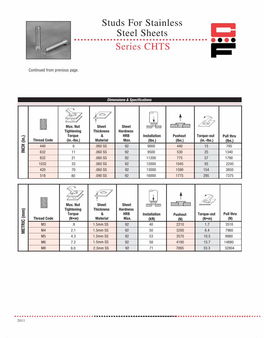
CHTS studs are made of heat treated stainless steelproviding a strong, flush-head assembly in stainlesssteel material as thin as .040 in. (1 mm) with hightorque-out and pushout performance.
CHTS 400 Series PassivatedStainless Steel ASTM A380
Series Material Finish
CHTS 440-48Length Code
Thread Code
Series
Part Number Structure:
Thread: External 2A, ANSI B1.1 (6g ANSI/ASME B1.13M).Use in: CHTS - Materials with HRB-92 or less.
071112 Captive_2011_Text_Catalog 12/5/12 8:20 AM Page 45

Continued from previous page.
Installation Procedure Drill or punch the proper size hole in the parent material and apply the recommended force, with a standard shop press, to fully seat the fastener. For best results, a flat punch with a minimum hardness of Rockwell C55 should beused along with a special anvil that has a raised ring. This will assure full displacement of the stainless sheet material into the clinch ring of the stud.Be sure to monitor the height of the ring on the anvil periodically and replace anvil when ring height wears down to .005 in. (.13 mm) to assure desired performance.
Anvil Dimensions (in.) Thread Code
E F G H R1 R2
440 .113 .144 .174 .010 .003 .005 632 .140 .170 .200 .010 .003 .005 832 .166 .202 .236 .010 .003 .005 IN
CH (i
n.)
1032 .191 .235 .275 .010 .003 .005
Anvil Dimensions (mm) Thread Code
E F G H R1 R2
M3 3.05 3.81 4.57 .25 .08 .13M4 4.04 4.95 5.82 .25 .08 .13M5 5.08 6.15 7.16 .25 .08 .13M
ETRI
C (m
m)
M6 6.05 7.87 8.79 .51 .08 .13
RAISED RING ANVIL
M8 7.95 9.78 10.27 .51 .08 .13
420 .251 .310 .363 .020 .003 .005 518 .313 .385 .474 .020 .003 .005
Studs For Stainless Steel Sheets
Series CHTS
071112 Captive_2011_Text_Catalog 12/5/12 8:20 AM Page 46
2011
Dimensions & Specifications
Thread Code
Max. Nut Tightening
Torque (in.-lbs.)
Sheet Thickness
& Material
Sheet Hardness
HRB Max.
Installation (lbs.)
Pushout (lbs.)
Torque-out(in.-lbs.)
Pull thru (lbs.)
440 6 .060 SS 92 9000 440 15 795
632 11 .060 SS 92 9500 530 25 1340
832 21 .060 SS 92 11200 775 57 1790
1032 33 .060 SS 92 12000 1045 93 2245
420 70 .060 SS 1590 154 3850
INCH
(in.
)
518 .090 SS 92 16000 1775 295 7375
Thread Code
Max. Nut Tightening
Torque (N•m)
Sheet Thickness
& Material
Sheet Hardness
HRB Max.
Installation (kN)
Pushout (N)
Torque-out (N•m)
Pull thru (N)
M3 .9 1.5mm SS 92 40 2210 1.7 3510
M4 2.1 1.5mm SS 92 50 3200 6.4 7960
M5 4.3 1.5mm SS 92 53 3570 10.5 9980
M6 7.2 92 58 4195 15.7 14880
MET
RIC
(mm
)
M8
92 13000
80
1.5mm SS
2.3mm SS 9.0 92 71 7895 33.3 32804
Continued from previous page.
Studs For Stainless Steel SheetsSeries CHTS
071112 Captive_2011_Text_Catalog 12/5/12 8:20 AM Page 47

CFA & CFC concealed-head studs allow permanent mounting inthin metal sheets, using a hollow punch and solid anvil. Thestud head is pressed permanently into a blind milled hole, withno marring of the exterior surface. CFA 2024-T4 None
Aluminum
CFC 300 Series PassivatedStainless Steel ASTM A380
Series Material Finish
Thread: External 2A, ANSI B1.1 (6g ANSI/ASME B1.13M).*Use in: CFA - HRB-50 or less.
CFC - HRB-70 or less.
LD
A
.062 in.
1.6mm
Max.
B
Dimensions & Specifications
Dimensions & Specifications
INCH
(in.
)
†Not stocked, available on special order. Continued on next page.
CFA-1-440-4Length CodeThread CodeShank LengthSeries
Part Number Structure:
*See Note 3 on Page 6 for Gauging Spec.
ThreadSize
Material
ThreadCode
LLength± .015
(Length Code is in 16ths of an inch)
Min.
BlindMounting
Hole Dia.
+.003-.000
Min.
Depth
Of
Blind
Hole
DMax.
B± .010
AMax. Min.
Max.Hole in
AttachedPartsAluminum
StainlessSteel .250 .375 .500 .625 .750 1.00
#4-40CFA-1 CFC-1
440 -4 -6 -8 -10 -12.062
.172.043 .041
.205 .171 .156 .135CFA-2 CFC-2 .093 .075 .071
#6-32CFA-1 CFC-1
632 -4 -6 -8 -10 -12 -16.062
.213.043 .041
.250 .212 .188 .160CFA-2 CFC-2 .093 .075 .071
#8-32CFA-1 CFC-1
832 -4 -6 -8 -10 -12 -16.062
.290.043 .041
.328 .289 .219 .185CFA-2 CFC-2 .093 .075 .071
#10-32CFA-1 CFC-1
1032 -6 -8 -10 -12 -16.062
.312.043 .041
.350 .311 .250 .210CFA-2 CFC-2 .093 .075 .071
MET
RIC
(mm
)
ThreadSize
MaterialThreadCode
LLength
± .4(Length Code is in mm)
Min.
BlindMounting
Hole Dia.
+.08-.00
Min.
Depth
Of
Blind
Hole
DMax.
B± .25
AMax. Min.
Max.Hole in
AttachedPartsAluminum
StainlessSteel 6 8 10 12 16 20 25
M3x0.5CFA-1 CFC-1
M3 -6 -8 -10 -12 -16 -201.6
4.41.09 1.04
5.21 4.35 4 3.6CFA-2 CFC-2 2.4 1.91 1.8
M4x0.7CFA-1 CFC-1
M4 -6 -8 -10 -12 -16 -20 -251.6
7.41.09 1.04
8.33 7.35 5.6 4.6CFA-2 CFC-2 2.4 1.91 1.8
M5x0.8CFA-1 CFC-1
M5 -10 -12 -16 -20 -251.6
7.951.09 1.04
8.89 7.9 6.4 5.6CFA-2 CFC-2 2.4 1.91 1.8
Series CFA & CFC
Self-ClinchingConcealed-Head Studs
071112 Captive_2011_Text_Catalog 12/5/12 8:20 AM Page 48

2011
Continued from previous page.
INCH
(in.
)
Installation & Performance Data
MET
RIC
(mm
)
TypeThread Code
TighteningTorqueMax.
(in.-lbs.)
Sheet MaterialCold-rolled Steel 5052-H34 Aluminum
InstallationForce(lbs.)
Pullout(lbs.)
InstallationForce(lbs.)
Pullout(lbs.)
CFC-1
440 4.75 1800 240 1400 130632 9 2500 260 1800 160832 18 4000 270 2800 1801032 32 5000 290 4000 210
CFC-2
440 4.75 2000 240 1500 200632 9 2700 350 2500 260832 18 3300 440 3000 3101032 32 4000 680 3500 360
CFA-1
440 2.85 N/A N/A 1400 125632 5.4 N/A N/A 1800 135832 10.8 N/A N/A 2800 1451032 19.2 N/A N/A 4000 170
CFA-2
440 2.85 N/A N/A 1500 190632 5.4 N/A N/A 2500 220832 10.8 N/A N/A 3000 2401032 19.2 N/A N/A 3500 300
TypeThread Code
Max.(N•m) (kN) (N) (kN) (N)
CFC-1M3 .5 8 1065 6.2 575M4 2 17.8 1200 12.5 800M5 3.6 22.2 1290 17.8 930
CFC-2M3 .5 8.9 1065 6.7 890M4 2 14.7 1955 13.3 1375M5 3.6 17.8 3020 15.6 1600
CFA-1M3 .3 N/A N/A 6.2 555M4 1.2 N/A N/A 12.5 645M5 2.16 N/A N/A 17.8 755
CFA-2M3 .3 N/A N/A 6.7 845M4 1.2 N/A N/A 13.3 1065M5 2.16 N/A N/A 15.6 1330
Self-ClinchingConcealed-Head Studs
Series CFA & CFC
071112 Captive_2011_Text_Catalog 12/5/12 8:20 AM Page 49

Self-ClinchingConcealed-Head Studs
1. Mill a blind hole in material to specified depth.*
2. Place fastener into hole in anvil.
3. Place sheet material over head of fastener.
4. Apply a downward squeezing force with punch,
pressing on sheet material until serrated collar
of fastener is flush with surface.
*Depth of blind holes may be greater than minimum, if sheet thickness allows.
Series CFA & CFCTypical Installation Method
Continued from previous page.
Installation Procedure
Anvil ‘D’ Diameter Dimensions for Concealed Head Studs
INCH
(in.
)
Series Thread CodeD
Dia. (in.)
CFACFC
440 .127
632 .152
832 .179
1032 .205
MET
RIC
(mm
)
Series Thread CodeD
Dia. (mm)
CFACFC
M3 3.4
M4 4.4
M5 5.4
071112 Captive_2011_Text_Catalog 12/5/12 8:20 AM Page 50
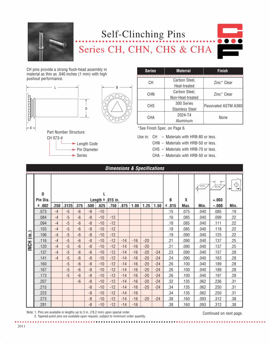
2011
Self-Clinching Pins
Series CH, CHN, CHS & CHA
CH pins provide a strong flush-head assembly inmaterial as thin as .040 inches (1 mm) with highpushout performance.
CH Carbon Steel, Zinc* ClearHeat-treated
CHN Carbon Steel, Zinc* ClearNon-Heat-treated
CHS 300 Series Passivated ASTM A380Stainless Steel
CHA 2024-T4 NoneAluminum
Series Material Finish
Dimensions & Specifications
X
L
D
B
D LPin Dia. Length ± .015 in. B X +.003± .002 .250 .3125 .375 .500 .625 .750 .875 1.00 1.25 1.50 ± .015 Max. Min. –.000 Min..073 -4 -5 -6 -8 -10 .15 .075 .040 .085 .19.084 -4 -5 -6 -8 -10 -12 .16 .085 .040 .099 .22.094 -4 -5 -6 -8 -10 -12 .18 .085 .040 .111 .22.103 -4 -5 -6 -8 -10 -12 .18 .085 .040 .118 .22.106 -4 -5 -6 -8 -10 -12 .19 .090 .040 .125 .22.116 -4 -5 -6 -8 -10 -12 -14 -16 -20 .21 .090 .040 .137 .25.120 -4 -5 -6 -8 -10 -12 -14 -16 -20 .21 .090 .040 .137 .25.137 -4 -5 -6 -8 -10 -12 -14 -16 -20 -24 .23 .090 .040 .157 .28.141 -4 -5 -6 -8 -10 -12 -14 -16 -20 -24 .24 .090 .040 .163 .28.160 -5 -6 -8 -10 -12 -14 -16 -20 -24 .26 .100 .040 .189 .28.167 -5 -6 -8 -10 -12 -14 -16 -20 -24 .26 .100 .040 .189 .28.173 -5 -6 -8 -10 -12 -14 -16 -20 -24 .26 .100 .040 .197 .28.207 -6 -8 -10 -12 -14 -16 -20 -24 .32 .135 .062 .236 .31.215 -8 -10 -12 -14 -16 -20 -24 .34 .135 .062 .250 .31.223 -8 -10 -12 -14 -16 .34 .135 .062 .250 .31.273 -8 -10 -12 -14 -16 -20 -24 .38 .160 .093 .312 .38.281 -8 -10 -12 -14 -16 .38 .160 .093 .312 .38
INCH
(in.
)
Part Number Structure:CH 073-4
Length CodePin DiameterSeries
*See Finish Spec. on Page 6.
Continued on next page.Note: 1. Pins are available in lengths up to 3 in. (76.2 mm) upon special order.2. Tapered-point pins are available upon request, subject to minimum order quantity.
Use in: CH – Materials with HRB-80 or less.CHN – Materials with HRB-50 or less.CHS – Materials with HRB-70 or less.CHA – Materials with HRB-50 or less.
071112 Captive_2011_Text_Catalog 12/5/12 8:20 AM Page 51
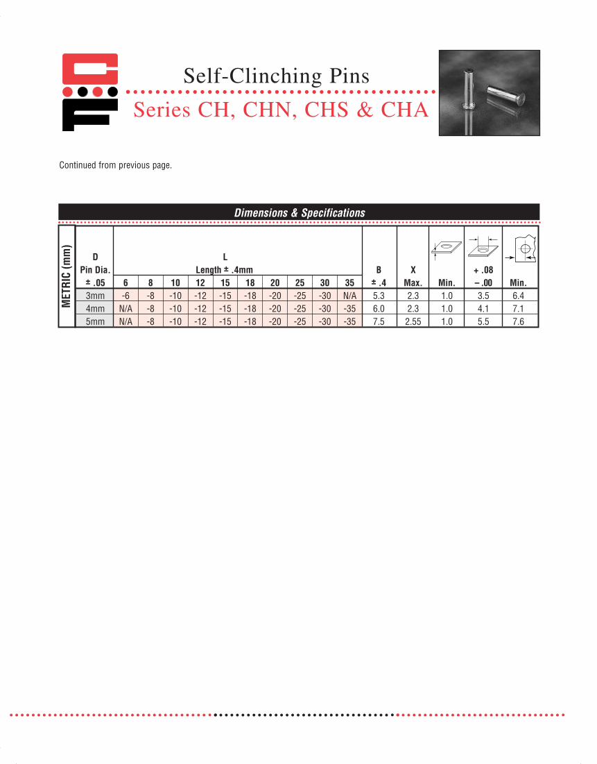
Self-Clinching Pins
Series CH, CHN, CHS & CHA
Continued from previous page.
Dimensions & Specifications
D LPin Dia. Length ± .4mm B X + .08
± .05 6 8 10 12 15 18 20 25 30 35 ± .4 Max. Min. – .00 Min.3mm -6 -8 -10 -12 -15 -18 -20 -25 -30 N/A 5.3 2.3 1.0 3.5 6.44mm N/A -8 -10 -12 -15 -18 -20 -25 -30 -35 6.0 2.3 1.0 4.1 7.15mm N/A -8 -10 -12 -15 -18 -20 -25 -30 -35 7.5 2.55 1.0 5.5 7.6
MET
RIC
(mm
)
071112 Captive_2011_Text_Catalog 12/5/12 8:20 AM Page 52
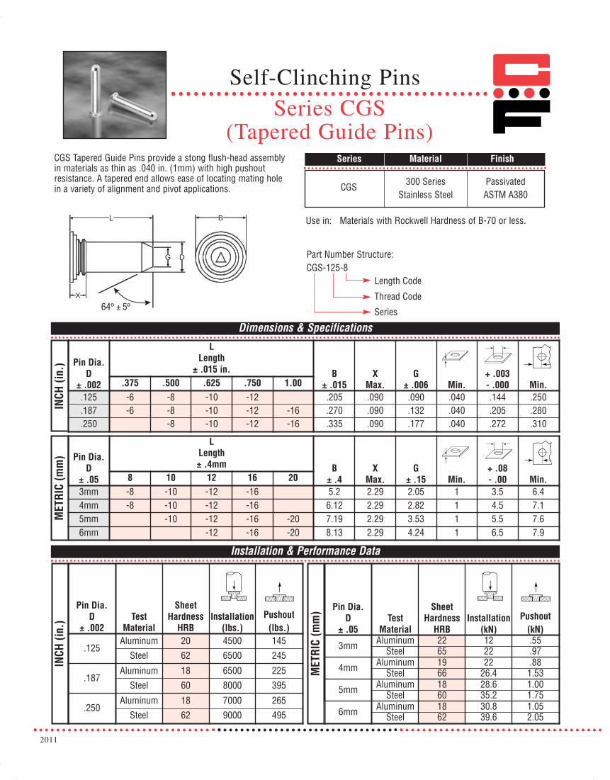
2011
Self-Clinching PinsSeries CGS
(Tapered Guide Pins)CGS Tapered Guide Pins provide a stong flush-head assemblyin materials as thin as .040 in. (1mm) with high pushoutresistance. A tapered end allows ease of locating mating holein a variety of alignment and pivot applications. CGS 300 Series Passivated
Stainless Steel ASTM A380
Series Material Finish
Use in: Materials with Rockwell Hardness of B-70 or less.
Dimensions & Specifications
Installation & Performance Data
INCH
(in.
)IN
CH (i
n.)
CGS-125-8Length Code
Thread Code
Series
Part Number Structure:
Pin Dia.D
± .002
LLength
± .015 in. B± .015
XMax.
G± .006 Min.
+ .003- .000 Min..375 .500 .625 .750 1.00
.125 -6 -8 -10 -12 .205 .090 .090 .040 .144 .250
.187 -6 -8 -10 -12 -16 .270 .090 .132 .040 .205 .280
.250 -8 -10 -12 -16 .335 .090 .177 .040 .272 .310
MET
RIC
(mm
) Pin Dia.D
± .05
LLength± .4mm B
± .4X
Max.G
± .15 Min.+ .08- .00 Min.8 10 12 16 20
3mm -8 -10 -12 -16 5.2 2.29 2.05 1 3.5 6.44mm -8 -10 -12 -16 6.12 2.29 2.82 1 4.5 7.15mm -10 -12 -16 -20 7.19 2.29 3.53 1 5.5 7.66mm -12 -16 -20 8.13 2.29 4.24 1 6.5 7.9
MET
RIC
(mm
)Pin Dia.D
± .002Test
Material
SheetHardness
HRBInstallation
(lbs.)Pushout
(lbs.)
.125Aluminum 20 4500 145
Steel 62 6500 245
.187Aluminum 18 6500 225
Steel 60 8000 395
.250Aluminum 18 7000 265
Steel 62 9000 495
Pin Dia.D
± .05Test
Material
SheetHardness
HRBInstallation
(kN)Pushout
(kN)
3mm Aluminum 22 12 .55Steel 65 22 .97
4mm Aluminum 19 22 .88Steel 66 26.4 1.53
5mm Aluminum 18 28.6 1.00Steel 60 35.2 1.75
6mm Aluminum 18 30.8 1.05Steel 62 39.6 2.05
BL
X
DG
64º ± 5º
071112 Captive_2011_Text_Catalog 12/5/12 8:20 AM Page 53

CKF2 and CKFS2 broaching-type fasteners are designed foruse on printed circuit boards and on most brittle or hardmaterials; such as, glass laminates, epoxy or resin with paper,nylon, or canvas bases. They are also used on materials toothin or unsuitable for threading, such as acrylic and polycarbonate panels.Since the aforementioned materials do not flow underpressure, these fasteners are designed with a knurled shankthat can be pressed into a drilled hole. The shank grips theboard with an interference fit by broaching its way into thepanel as it is squeezed into the holes.
Series Material Finish
CKF2 Carbon Steel Electro tin plating(Zinc* optional)
CKFS2 300 Series Passivated ASTM A380Stainless Steel
*See Finish Spec. on Page 6.
Thread: Internal 2B, ANSI B1.1 (6H, ANSI/ASME B1.13M).Use in: Materials with Rockwell Hardness of B-60 or less.
Dimensions & Specifications
Thread Part Number A B C + .003Size Carbon Steel Stainless Steel ± .003 ± .005 ± .005 –.000 Min. Min.
#2-56 CKF2256 CKFS2256 .165 .219 .065 .147 .16 .060#4-40 CKF2440 CKFS2440 .184 .219 .065 .166 .17 .060#6-32 CKF2632 CKFS2632 .231 .281 .065 .213 .22 .060#8-32 CKF2832 CKFS2832 .268 .344 .096 .250 .25 .060#10-24 CKF21024 CKFS21024 .290 .375 .127 .272 .28 .060#10-32 CKF21032 CKFS21032 .290 .375 .127 .272 .28 .060Thread Part Number A B C + .08
Size Carbon Steel Stainless Steel ± .08 ± .13 ± .13 –.00 Min. Min.M2 x 0.4 CKF2M2 CKFS2M2 4.19 5.56 1.5 3.7 4.2 1.5
M2.5 x 0.45 CKF2M2.5 CKFS2M2.5 4.68 5.56 1.5 4.2 4.5 1.5M3 x 0.5 CKF2M3 CKFS2M3 4.68 5.56 1.5 4.2 4.5 1.5M4 x 0.7 CKF2M4 CKFS2M4 6.81 8.74 2.0 6.4 6.4 1.5M5 x 0.8 CKF2M5 CKFS2M5 7.37 9.53 3.0 6.9 7.1 1.5
A
C
B
.060 in.
(1.5 mm)
MAX.
INCH
(in.
)M
ETRI
C (m
m)
Continued on next page.
Note: CKF2 & CKFS2 broaching fasteners are designed for unplated through-holes. When installed in plated through-holes, ahole tolerance of +.005 - .001 in. (+.13 - .03 mm) should be used.
When used in plated through-holes, performance will be reduced and plating may be damaged by knurl.
Broaching-Type Fasteners
Series CKF2 & CKFS2
071112 Captive_2011_Text_Catalog 12/5/12 8:20 AM Page 54

2011
INCH
(in.
)M
ETRI
C (m
m)
Fiberglass .060 in. (1.5 mm)
Thread Size Installation Force (lbs.) Pushout (lbs.) Torque-out (in.-lbs.)#2-56 400 60 6#4-40 400 65 15#6-32 500 80 30#8-32 700 95 35#10-24 700 100 40#10-32 700 100 40
Thread Size Installation Force (kN) Pushout (N) Torque-out (N•m)M2 2.22 265 .65
M2.5 2.22 285 1.35M3 2.22 285 1.70M4 2.90 415 3.95M5 2.90 435 4.52
Installation & Performance Data
Continued from previous page.
Broaching-Type Fasteners
Series CKF2 & CKFS2
071112 Captive_2011_Text_Catalog 12/5/12 8:20 AM Page 55

CKFE and CKFSE threaded and non-threaded standoffs allowscrews to be inserted through multiple layered boards forstacked assemblies. All fasteners from Captive Fastener areidentical to industry standards so that they can be fed throughstandard automatic insertion equipment.
Series Material Finish
CKFE Carbon Steel
CKFSE 300 Series Passivated ASTM A380Stainless Steel
*See Finish Spec. on Page 6.
Dimensions & Specifications
INCH
(in.
)
ThruHole L
Thread +.004 Part Number Length ± .005 in. A B +.003Size -.003 Carbon Steel Stainless Steel .125 .250 .375 .500 .625 .750 .875 ± .003 ± .005 -.000 Min.
#4-40 CKFE440 CKFSE440 -4 -8 -12 -16 -20 -24† .184 .219 .166 .17#6-32 CKFE632 CKFSE632 -4 -8 -12 -16 -20 -24† -28† .231 .281 .213 .22
.116 CKFE116 CKFSE116 -4 -8 -12 -16 -20 -24† .184 .219 .166 .17
.143 CKFE143 CKFSE143 -4 -8 -12 -16 -20 -24† -28† .231 .281 .213 .22E=minimum thread length Full .375 ± .015
Thread +.10 Part Number Length ± .13 mm A B +.08Size -.08 Carbon Steel Stainless Steel 3 4 6 8 10 12 14 16 ± .08 ±.13 -.00 Min.
M3x0.5 CKFEM3 CKFSEM3 -3 -4 -6 -8 -10 -12 -14 -16† 4.68 5.56 4.2 4.43.6 CKFE3.6 CKFSE3.6 -3 -4 -6† -8† -10† -12† -14† -16† 5.87 7.14 5.4 5.54.2 CKFE4.2 CKFSE4.2 -3† -4† -6† -8† -10† -12† -14† -16† 6.86 8.74 6.4 7.1
E=minimum thread length (where applicable) Full 9.5 ± .4
Thread: Internal 2B, ANSI B1.1 (6H, ANSI/ASME B1.13M).Use in: CKFE - Materials with Rockwell Hardness of B-60 or less.
CKFSE - Materials with Rockwell Hardness of B-70 or less.Part Number Structure:CKFE 440-4
Length CodeThread/Hole SizeSeries
AB
1.5 mm.060 in.
max.
EL
Installation & Performance Data
Fiberglass .060 in. (1.5 mm)
Thread Installation Force Pushout Torque-outSize (lbs.) (lbs.) (in.-lbs.)
#4-40 400 65 14#6-32 500 80 29Thread Installation Force Pushout Torque-out
Size (kN) (N) (N•m)M3 2.22 295 1.35
INCH
(in.)
MET
RIC
(mm
)M
ETRI
C (m
m)
Note: CKFE & CKFSE broaching standoffs are designed for unplatedthrough-holes. When installed inplated through-holes, a hole tolerance of +.005 - .001 in. (+.13 - .03 mm) should be used.
When used in plated through-holesperformance will be reduced andplating may be damaged by knurl.† Not stocked, available on special order. Note: Min Panel Thickness .060 in. (1.5mm)
Electro Tin PlatingASTM B545 Class B
(Zinc* Clear Optional)
Broaching-Type Standoffs
Series CKFE & CKFSE
071112 Captive_2011_Text_Catalog 12/5/12 8:20 AM Page 56
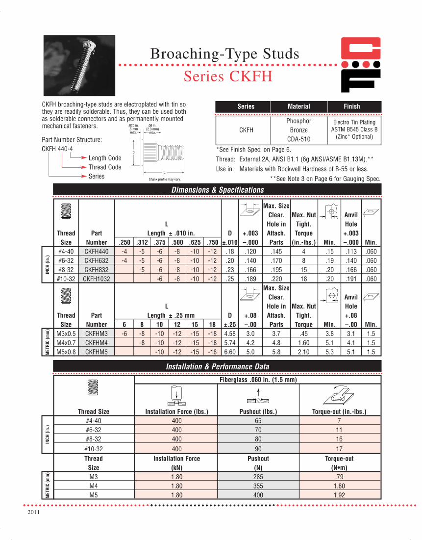
2011
L
D
.09 in. (2.3 mm)
max.
.020 in..5 mmmax.
Shank profile may vary.
CKFH broaching-type studs are electroplated with tin so they are readily solderable. Thus, they can be used both as solderable connectors and as permanently mountedmechanical fasteners.
Series Material Finish
PhosphorCKFH Bronze
CDA-510
Thread: External 2A, ANSI B1.1 (6g ANSI/ASME B1.13M).**Use in: Materials with Rockwell Hardness of B-55 or less.
**See Note 3 on Page 6 for Gauging Spec.
Dimensions & Specifications
Max. SizeClear. Max. Nut Anvil
L Hole in Tight. HoleThread Part Length ± .010 in. D +.003 Attach. Torque +.003
Size Number .250 .312 .375 .500 .625 .750 ±.010 –.000 Parts (in.-lbs.) Min. –.000 Min.#4-40 CKFH440 -4 -5 -6 -8 -10 -12 .18 .120 .145 4 .15 .113 .060#6-32 CKFH632 -4 -5 -6 -8 -10 -12 .20 .140 .170 8 .19 .140 .060#8-32 CKFH832 -5 -6 -8 -10 -12 .23 .166 .195 15 .20 .166 .060#10-32 CKFH1032 -6 -8 -10 -12 .25 .189 .220 18 .20 .191 .060
Max. SizeClear. Anvil
L Hole in Max. Nut HoleThread Part Length ± .25 mm D +.08 Attach. Tight. +.08
Size Number 6 8 10 12 15 18 ±.25 –.00 Parts Torque Min. –.00 Min.M3x0.5 CKFHM3 -6 -8 -10 -12 -15 -18 4.58 3.0 3.7 .45 3.8 3.1 1.5M4x0.7 CKFHM4 -8 -10 -12 -15 -18 5.74 4.2 4.8 1.60 5.1 4.1 1.5M5x0.8 CKFHM5 -10 -12 -15 -18 6.60 5.0 5.8 2.10 5.3 5.1 1.5
INCH
(in.
)
Installation & Performance Data
MET
RIC
(mm
)IN
CH (i
n.)
MET
RIC
(mm
)
Fiberglass .060 in. (1.5 mm)
Thread Size Installation Force (lbs.) Pushout (lbs.) Torque-out (in.-lbs.)#4-40 400 65 7#6-32 400 70 11#8-32 400 80 16#10-32 400 90 17Thread Installation Force Pushout Torque-out
Size (kN) (N) (N•m)M3 1.80 285 .79M4 1.80 355 1.80M5 1.80 400 1.92
*See Finish Spec. on Page 6.
Electro Tin PlatingASTM B545 Class B
(Zinc* Optional)Part Number Structure:CKFH 440-4
Length CodeThread CodeSeries
Broaching-Type Studs
Series CKFH
071112 Captive_2011_Text_Catalog 12/5/12 8:20 AM Page 57

CKFB3 flare mounted threaded standoffs provide a flared shank for stronger holding power and are used for spacing or stacking PC boards.
Thread: Internal 2B ANSI B1.1 (6H, ANSI/ASME B1.13M).Use in: Materials with Rockwell Hardness of B-65 or less.
Series Material Finish
CKFB3 BrassCDA-360
Dimensions & Specifications
LThread Part Length ± .005 in. A C B H +.005
Size Number .0625 .125 .1875 .250 .3125 .375 .500 .625 .750 ±.003 Max. ±.003 ±.005 –.001 Min. Min.#4-40 CKFB3440 -2 -4 -6 -8 -10 -12 -16 -20 .179 .165 .122 .22 .166 .17 .050#6-32 CKFB3632 -2 -4 -6 -8 -10 -12 -16 -20* -24* .226 .212 .171 .28 .213 .22 .065
“T” Minimum Full .375 ±.015thread length
INCH
(in.
)
Dimensions & Specifications
LThread Part Length ± .13 mm A C B H +.13
Size Number 2 3 4 6 8 10 12 14 16 ± .08 Max. ±.08 ±.13 –.03 Min. Min.M3x0.5 CKFB3M3 -2 -3 -4 -6 -8 -10 -12 -14 -16 4.55 4.22 3.20 5.56 4.2 4.33 1.27M4x0.7 CKFB3M4 -2 -3 -4 -6 -8 -10 -12 -14 -16 6.68 6.40 5.23 8.74 6.4 6.36 1.65
“T” Minimum Full 9.5 ± .4thread lengthM
ETRI
C (m
m)
TL
.04 in. (1.0 mm)
.09 in. (2.28 mm) MAX.
B C A
H
Installation & Performance Data
INCH
(in.)
MET
RIC
(mm
)
Fiberglass .060 in. (1.5 mm)
Thread Size Installation Force (lbs.) Pushout (lbs.) Torque-out (in.-lbs.)#4-40 1000 140 18#6-32 1500 170 28Thread Installation Force Pushout Torque-out
Size (kN) (N) (N•m)M3 4.4 560 2.02M4 6.0 680 3.20
*See Finish Spec. on Page 6.
Electro Tin PlatingASTM B545 Class B
(Zinc* Optional)
Part Number Structure:CKFB3 440-2
Length CodeThread CodeSeries
Flare Mounted Threaded Standoffs
Series CKFB3
071112 Captive_2011_Text_Catalog 12/5/12 8:20 AM Page 58

2011
Series Material Finish
CRMElectro Tin Plated,
ASTM B545, Class A w/ Preservative
Coating
L Length ± .005 in.
Thread Size Series
Thread Code
Thru Hole
+.004 -.003 .062 .125 .250 .375
A Max. Min.
+.003-.000
B Max.
D ±.005
Min. Solder Pad ø
#2-56 256 -2 -4 -8 .060 .060 .147 .142 .219 .244
#4-40 440 -2 -4 -8 .060 .060 .166 .161 .219 .244
#6-32 CRM 632 -2 -4 -8 .060 .060 .213 .208 .281 .306 #8-32 CRM 832 -2 -4 -8 .060 .060 .250 .245 .344 .369
CRM .116 -2 -4 -8 .060 .060 .166 .161 .219 .244
INCH
(in.
)
CRM .143 -2 -4 -8 .060 .060 .213 .208 .281 .306
2 3 4 6 8 10
M2 x 0.4 M2 -2 -3 -4 -6 -8 -10 1.53 1.53 3.73 3.6 5.56 6.2
M2.5 x 0.45 CRM M2.5 -2 -3 -4 -6 -8 -10 1.53 1.53 4.22 4.09 5.56 6.2
M3 x 0.5 M3 -2 -3 -4 -6 -8 -10 1.53 1.53 4.22 4.09 5.56 6.2 M3.5 x 0.6 M3.5 -2 -3 -4 -6 -8 -10 1.53 1.53 5.41 5.28 7.14 7.77
M4 x 0.7 M4 -2 -3 -4 -6 -8 -10 1.53 1.53 6.35 6.22 8.74 9.37
CRM 3.6 -2 -3 -4 -6 -8 -10 1.53 1.53 5.41 5.28 7.14 7.77
MET
RIC
(mm
)
CRM 4.2 -2 -3 -4 -6 -8 -10 1.53 1.53 6.35 6.22 8.74 9.37
Number of Parts per Reel / Pitch (mm) for Each Size – as per EIA standards (13” reels/24mm wide) Length Thread Size &
Thru Hole Size 2 3 4 6 8 10 12256, 440, 632, .116, .143 1500 / 12 -- 1000 / 12 -- 650 / 12 -- 300 / 16
832 1100 / 16 -- 800 / 16 -- 500 / 16 -- 300 / 16 M2, M2.5, M3, M3.5, 3.6 1500 / 12 1000 / 12 900 / 12 650 / 12 375 / 16 300 / 16 --
M4, 4.2 1100 / 16 800 / 16 675 / 16 500 / 16 375 / 16 300 / 16 --
CRM Reel Mount nuts and spacers provide alow-installed-cost solution for surface mount hardware.The fasteners are fed from the recyclable reel using “pickand place” equipment and oriented prior to the reflowsoldering operation.
Note: All Items Subject To Minimum Order
CRM- 440 - 4 Part Number Structure:
Thread: Internal 2B, ANSI B1.1 (6H, ANSI/ASME B1.13M).
Dimensions & Specifications
Length Code
Thread Code
Series
Carbon Steel
CRM
CRM -12
-12
-12 -12
-12
-12
L Length ± .13 mm
Thread Size Series
Thread Code
Thru Hole
+.10 -.08
A Max. Min.
+.08-.00
B Max.
D ±.13
Min. Solder Pad ø
CRM
CRM
CRM
CRM
Reel Mounted Spacers andNuts
Series CRM
071112 Captive_2011_Text_Catalog 12/5/12 8:20 AM Page 59

Dimensions & Specifications
Dimensions & Specifications
Top Board
Mounting Hole Length L ± .005 in.Diameter (Length Code In 32nds Of An Inch) B C E P T
Series Code .250 .312 .375 .437 .500 .562 .625 .750 .875 1.000 ± .005 ± .003 ± .005 ± .005 ± .005CFKSSB 156 -8 -10 -12 -14 -16 -18 -20 -24 -28 -32 .188 .226 .250 .141 .020
Top Board
Mounting Hole Length L ± .13mmDiameter (Length Code In Millimeters) B C E P T
Series Code 8 10 12 14 16 18 20 22 25 ± .13 ± .08 ± .13 ± .13 ± .13CFKSSB 4 MM -8 -10 -12 -14 -16 -18 -20 -22 -25 4.77 5.74 6.35 3.58 .51
INCH
(in.
)M
ETRI
C (m
m)
CB
LP
T
E
Part Number Structure:CFKSSB 156-8
Length CodeHole DiameterSeries
Use in: PC Boards with Rockwell HardnessB-65 or less.
CFKSSB spring-top standoffs are designed for permanentinstallation into PC boards by pressing into a drilled or punched hole. The spring-action post provides quickattachment and removal of PC boards, with a simple snapeliminating the problems associated with loose hardware.
Continued on next page.
Spring-Top Standoffs
Series CFKSSB
CFKSSB CDA-360 Brass None
Series Material Finish
071112 Captive_2011_Text_Catalog 12/5/12 8:20 AM Page 60

2011
Installation & Performance Data
Bottom Panel (Fixed) Top Panel (Removable)
Bottom TopMounting Mounting
Hole Location Hole+.003 Hardness Thickness Tolerance +.003 Thickness
Series –.000 Material Max. Min. Min. Max. –.000 Material Range Min.PC .040-
CFKSSB .213 PC board HRB65 .050 .220 ± .005 .156 board .070 .100or metalIN
CH (i
n.)
Installation & Performance Data
Bottom Panel (Fixed) Top Panel (Removable)
Bottom TopMounting Mounting
Hole Location Hole+.08 Hardness Thickness Tolerance +.08 Thickness
Series –.00 Material Max. Min. Min. Max. –.00 Material Range Min.PC 1-
CFKSSB 5.4 PC board HRB65 1.25 5.6 ± .13 4.0 board 1.8 2.5or metalM
ETRI
C (m
m)
Continued from previous page.
Installation & Performance Data
Installation & Performance Data
Bottom Panel (Fixed) Top Panel (Removable)
Sheet Thickness Installation Pushout Max. first on Min. first off Min. 15th offSeries & Sheet Material (lbs.) (lbs.) force (lbs.) force (lbs.) force (lbs.)
CFKSSB .060 FR-4 Fiberglass 500 110 13 3.0 1.0
Bottom Panel (Fixed) Top Panel (Removable)
Sheet Thickness Installation Pushout Max. first on Min. first off Min. 15th offSeries & Sheet Material (kN) (N) force (N) force (N) force (N)
CFKSSB 1.52 FR-4 Fiberglass 2.2 484 58 13 4.0
INCH
(in.
)M
ETRI
C (m
m)
Spring-Top Standoffs
Series CFKSSB
071112 Captive_2011_Text_Catalog 12/5/12 8:20 AM Page 61

CPFK PC board panel fasteners provide permanent attachment ofscrew assemblies to PC board substrate material. Screw assem-blies remain captive for easy mounting and removal of board.
CPFK 300 Series PassivatedStainless Steel ASTM A380
Series Material Finish
Dimensions & Specifications
INCH
(in.
)M
ETRI
C (m
m)
D+.016 in.
G P L (.4mm) Y B C +.003 in.
Thread Part ± .016 in. ± .016 in. ± .016 in. -.010 in. A ± .005 in. ± .010 in. ± .003 in. (.08 mm)
Size Number (.4 mm) (.4 mm) (.4 mm) (.25 mm) Max. (.13 mm) (.25mm) (.08mm) –.000(.00) Min.CPFK440-40 .250 .000
#4-40 CPFK440-62 .375 .125 .19 .310 .36 .072 .28 .283 .265 .20CPFK440-84 .500 .250CPFK632-40 .250 .000
#6-32 CPFK632-62 .375 .125 .19 .340 .36 .072 .28 .299 .281 .26 CPFK632-84 .500 .250CPFKM3-40 6.4 .0
M3 x 0.5 CPFKM3-62 9.5 3.2 4.8 7.92 9.15 1.83 7.2 7.19 6.73 5.1CPFKM3-84 12.7 6.4
C
L
B
PG
A
D
Y
Glass Filled NylonRetaining Ring
Min. Panel Thickness.060 in. (1.5 mm)
Installation & Performance Data
INCH
(in
.)M
ETRI
C (m
m)
Fiberglass .060 in. (1.5 mm)
Installation Torque-Thread Force Pushout out
Size (lbs.) (lbs.) (in.-lbs.)#4-40 250 55 (1)#6-32 400 60 (1)
Installation Torque-Thread Force Pushout out
Size (kN) (N) (N•m)M3 1.1 245 (3)
Thread: External 2A, ANSI B1.1 (6g ANSI/ASME B1.13M).*Use in: PC Boards with Rockwell Hardness of B-70 or less.
*See Note 3 on Page 6 for Gauging Spec.
PC Board Panel Fasteners
Series CPFK
071112 Captive_2011_Text_Catalog 12/5/12 8:20 AM Page 62

2011
Low-Profile Panel Fastener
Series LPH
C
T
A2Y
D
A1
G
Series Material Finish*
LPH Carbon Bright Nickel overSteel Copper Flash
LPH panel fasteners are preassembled for attachment toremovable sheet metal panels. Screw assemblies remaincaptive for servicing ease and provide low profile when secure.Slotted head with deep skirt allows tool or finger operation.
Thread: External 2A, ANSI B1.1 (6g ANSI/ASME B1.13M).**Use in: Materials with Rockwell Hardness of B-60 or less.
Dimensions & Specifications
INCH
(in.
)
LPH-0 440-30Length CodeThread CodeShank LengthSeries
Part Number Structure:
**See Note 3 on Page 6 for Gauging Spec.
ThreadSize Type
ThreadCode
ScrewLengthCode Min.
TMax.
G±.015
CMax.
D±.010
Y±.005
A1Max.
A2Nom.
+.003-.000 Min.
#4-40LPH-0
440 30.030 .030
.300 .202 .406 .202 .325 .595 .203 .26LPH-1 .040 .038LPH-2 .060 .058
#6-32LPH-0
632 30.030 .030
.300 .218 .438 .202 .325 .595 .219 .28LPH-1 .040 .038LPH-2 .060 .058
#8-32LPH-0
832 30.030 .030
.300 .249 .468 .207 .330 .600 .250 .29LPH-1 .040 .038LPH-2 .060 .058
#10-32LPH-0
1032 30.030 .030
.300 .311 .530 .220 .335 .605 .312 .33LPH-1 .040 .038LPH-2 .060 .058
1/4-20 LPH-2 420 35 .060 .058 .350 .374 .625 .242 .385 .675 .375 .38
ThreadSize Type
ThreadCode
ScrewLengthCode Min.
TMax.
G±.4
CMax.
D±.25
Y±.13
A1Max.
A2Nom.
+.08-.00 Min.
M3 x 0.5LPH-0
M3 30.76 .76
7.62 5.48 10.31 5.13 8.26 15.11 5.5 6.6LPH-1 1 .97LPH-2 1.5 1.48
M4 x 0.7LPH-0
M4 30.76 .76
7.62 6.38 11.89 5.26 8.38 15.24 6.4 7.37LPH-1 1 .97LPH-2 1.5 1.48
M5 x 0.8LPH-0
M5 30.76 .76
7.62 7.98 13.46 5.59 8.51 15.37 8 8.38LPH-1 1 .97LPH-2 1.5 1.48
M6 x 1 LPH-2 M6 35 1.5 1.48 8.89 9.48 15.88 6.12 9.78 17.15 9.5 9.65
MET
RIC
(mm
)
*Black Nitride (BN) finish available
071112 Captive_2011_Text_Catalog 12/5/12 8:20 AM Page 63

Low-Profile Panel Fastener
Series LPH
Continued from previous page.
Installation & Performance Data
Installation & Performance Data
INCH
(in.
)
TypeThreadCode
Sheet Material5052-H34 Aluminum Cold-rolled Steel (B-60 Max)
InstallationForce (lbs.)
Pushout(lbs.)
InstallaionForce (lbs.)
Pushout(lbs.)
LPH-0440 2200
645000
90LPH-1 105 110LPH-2 185 300LPH-0
632 240066
550090
LPH-1 105 130LPH-2 190 300LPH-0
832 280068
600090
LPH-1 110 130LPH-2 200 300LPH-0
1032 350072
800095
LPH-1 150 160LPH-2 260 425LPH-2 420 4300 320 12000 450
TypeThreadCode
Sheet Material5052-H34 Aluminum Cold-rolled Steel (B-60 Max)
InstallationForce (kN)
Pushout(N)
InstallaionForce (kN)
Pushout(N)
LPH-0M3 9.8
28522.2
400LPH-1 465 489LPH-2 823 1334LPH-0
M4 12.5302
26.7400
LPH-1 489 578LPH-2 890 1334LPH-0
M5 15.6320
35.6423
LPH-1 667 712LPH-2 1156 1890LPH-2 M6 19.1 1423 53.4 2002
MET
RIC
(mm
)
071112 Captive_2011_Text_Catalog 12/5/12 8:20 AM Page 64

2011
CPFC2 panel fasteners provide permanent attachment of screwassemblies to removable sheet metal panels. Pre-assembledscrew assemblies remain captive for easy mounting andremoval of panel. CPFC2 300 Series Passivated
Stainless Steel ASTM A380
Series Material Finish
Dimensions & Specifications
INCH
(in.
)
DThread Part G P L +.016 A Y B C +.003
Size Number ± .016 ± .016 ± .016 –.010 Max. ±.005 ±.010 Max. –.000 Min.CPFC2440-40 .250 .000
#4-40 CPFC2440-62 .375 .125 .19 .31 .36 .072 .28 .264 .265 .25CPFC2440-84 .500 .250CPFC2632-40 .250 .000
#6-32 CPFC2632-62 .375 .125 .19 .34 .36 .072 .28 .280 .281 .28CPFC2632-84 .500 .250CPFC2832-50 .312 .000
#8-32 CPFC2832-72 .437 .125 .25 .38 .45 .082 .36 .311 .312 .31CPFC2832-94 .562 .250CPFC21032-50 .312 .000
#10-32 CPFC21032-72 .437 .125 .25 .41 .45 .082 .36 .343 .344 .34CPFC21032-94 .562 .250CPFC2420-60 .375 .000
1/4-20 CPFC2420-82 .500 .125 .31 .47 .58 .097 .47 .412 .413 .38CPFC2420-04 .625 .250
Thread: External 2A, ANSI B1.1 (6g, ANSI/ASME B1.13M).Use in: Materials with Rockwell Hardness B-70 or less.
Continued on next page.
Min. Panel Thickness.060 in. (1.5mm)
NylonRetaining Ring
Pre-Assembled Panel Fasteners
Series CPFC2
Part Number Structure:CPFC2 440-40
Length CodeThread CodeSeries
071112 Captive_2011_Text_Catalog 12/5/12 8:20 AM Page 65

Dimensions & Specifications
Installation & Performance Data
INCH
(in.
)M
ETRI
C (m
m)
MET
RIC
(mm
)
DThread Part G P L +.4 A Y B C +.08
Size Number ± .4 ± .4 ± .4 –.25 Max. ± .13 ± .25 Max. –.00 Min.CPFC2M3-40 6.4 .0
M3 x 0.5 CPFC2M3-62 9.5 3.2 4.8 7.9 9.1 1.83 7.2 6.7 6.75 6.4CPFC2M3-84 12.7 6.4CPFC2M4-50 7.9 .0
M4 x 0.7 CPFC2M4-72 11.1 3.2 6.4 9.5 11.4 2.08 9.3 7.9 7.95 7.9CPFC2M4-94 14.3 6.4CPFC2M5-50 7.9 .0
M5 x 0.8 CPFC2M5-72 11.1 3.2 6.4 10.3 11.4 2.08 9.3 8.7 8.75 8.7CPFC2M5-94 14.3 6.4CPFC2M6-60 9.5 .0
M6 x 1.0 CPFC2M6-82 12.7 3.2 7.9 11.9 14.6 2.46 12.0 10.5 10.5 9.5CPFC2M6-04 15.9 6.4
Continued from previous page.
Cold-rolled Steel 5052-H34 Aluminum
Installation InstallationThread Force Pushout Force Pushout
Size (lbs.) (lbs.) (lbs.) (lbs.)#4-40 3000 300 2400 240#6-32 3500 350 2700 275#8-32 3800 400 2900 300#10-32 4000 500 3000 4001/4-20 5000 600 3500 400
(kN) (N) (kN) (N)M3 13.3 1330 10.7 1070M4 16.9 1780 12.9 1330M5 17.8 2220 13.3 1780M6 22.2 2670 15.6 1780
Pre-Assembled Panel Fasteners
Series CPFC2
071112 Captive_2011_Text_Catalog 12/5/12 8:21 AM Page 66

2011
CFSO self-clinching standoffs are designed for quick, easyinstallation with any standard pneumatic, hydraulic ormechanical press. Through-threaded standoffs are used inmetal panels with thickness of .040 in. (1.0 mm) and up.No secondary operation, such as reaming or deburring, is necessary prior to installation.
Dimensions & Specifications
Series Material Finish
Thread: Internal 2B, ANSI B1.1 (6H, ANSI/ASME B1.13M).Use in: CFSO for materials with Rockwell Hardness of
B-80 or less.CFSOS for materials with Rockwell Hardness ofB-70 or less.CFSOA for materials with Rockwell Hardness ofB-50 or less.
D ±.0156 None .1875 .3125 .4375
All Measurements In Inches.
H
LD
C A
Through Threads
LT
*See Finish Spec. on Page 6.
Part Number Structure:CFSOS 6440-4
Length CodeThread CodeBody Code (if applicable)Series
LLength+.002
-.005 in.
Self-Clinching Standoffs
Series CFSO, CFSOS, CFSOA
CFSO
CFSOS 440
CFSOA
CFSO
CFSOS 6440
CFSOA
-4 -6 -8 -10 -12 -14 -16 -18 -20 -22 -24
-4 -6 -8 -10 -12 -14 -16 -18 -20 -22 -24
(Through Threads)
A H CDim. Hex Counter-
Thread Part +.003 +.000 Dim. bore
Size Number –.000 –.005 (Nom.) ±.005 Min. Min.
#4-40 .166 .165 .1875 .125 .23 .040
#4-40 .213 .212 .25 .125 .27 .040
.125 .1875 .250 .3125 .375 .4375 .500 .5625 .625 .6875 .750 .8125 .875 .9375 1.00 1.0625
CFSO Heat-treatedCarbon Steel Zinc* Clear
CFSOS 300 SeriesStainless Steel
PassivatedASTM A380
CFSOA 7075-T6 Aluminum None
071112 Captive_2011_Text_Catalog 12/5/12 8:21 AM Page 67

A H CDim. Hex Counter-
Thread Part +.003 +.000 Dim. bore
Size Number –.000 –.005 (Nom.) ±.005 Min. Min.
#6-32 .213 .212 .25 .156 .27 .04
#6-32 .281 .280 .3125 .156 .31 .05
#8-32 .281 .280 .3125 .188 .31 .05
#10-32 .281 .280 .3125 .203 .31 .05
Dimensions & Specifications
D ±.0156 None .1875 .3125 .4375
Continued from previous page.
All Measurements In Inches.
.125 .1875 .250 .3125 .375 .4375 .500 .5625 .625 .6875 .750 .8125 .875 .9375 1.00 1.0625
H
LD
C A
Through Threads
Self-Clinching Standoffs
-4 -6 -8 -10 -12 -14 -16 -18 -20 -22 -24 -26 -28 -30 -32 -34
-4 -6 -8 -10 -12 -14 -16 -18 -20 -22 -24 -26 -28 -30 -32 -34
-4 -6 -8 -10 -12 -14 -16 -18 -20 -22 -24 -26 -28 -30 -32 -34
-4 -6 -8 -10 -12 -14 -16 -18 -20 -22 -24 -26 -28 -30 -32 -34
CFSO
CFSOS 632
CFSOA
CFSO
CFSOS 8632
CFSOA
CFSO
CFSOS 832
CFSOA
CFSO
CFSOS 1032
CFSOA
Series CFSO, CFSOS, CFSOA(Through Threads)
LLength+.002
–.005 in.
071112 Captive_2011_Text_Catalog 12/5/12 8:21 AM Page 68

2011
Dimensions & Specifications
A H CDim. Hex Counter-
Thread Part +.08 +.00 Dim. bore
Size Number –.00 –.13 (Nom.) ± .13 Min. Min.
M3x0.5 4.22 4.19 4.8 3.2 6.0 1.0
M3x0.5 5.41 5.38 6.4 3.2 7.0 1.0
M3.5x0.6 5.41 5.38 6.4 4.0 7.0 1.0
M4x0.7 7.14 7.11 7.9 4.8 8.0 1.3
M5x0.8 7.14 7.11 7.9 5.35 8.0 1.3
All Measurements In Millimeters.
Continued from previous page.
3 4 6 8 10 12 14 16 18 20 22 25
H
LD
C A
Through Threads
D ± .4 None 4.0 8.0 11.0
Self-Clinching Standoffs
-3 -4 -6 -8 -10 -12 -14 -16 -18
-3 -4 -6 -8 -10 -12 -14 -16 -18
-3 -4 -6 -8 -10 -12 -14 -16 -18 -20 -22 -25
-3 -4 -6 -8 -10 -12 -14 -16 -18 -20 -22 -25
-3 -4 -6 -8 -10 -12 -14 -16 -18 -20 -22 -25
CFSO
CFSOS M3
CFSOA
CFSO
CFSOS 3.5M3
CFSOA
CFSO
CFSOS M3.5
CFSOA
CFSO
CFSOS M4
CFSOA
CFSO
CFSOS M5
CFSOA
Series CFSO, CFSOS, CFSOA(Through Threads)
LLength+.05
–.13 mm
071112 Captive_2011_Text_Catalog 12/5/12 8:21 AM Page 69

.3125 .375 .4375 .500 .5625 .625 .6875 .750 .8125 .875 .9375 1.00 1.0625
-10 -12 -14 -16 -18 -20 -22 -24 -26 -28 -30 -32 -34
-10 -12 -14 -16 -18 -20 -22 -24 -26 -28 -30 -32 -34
CFBSO self-clinching standoffs are designed for quick, easyinstallation with any standard pneumatic, hydraulic ormechanical press. Blind standoffs are used in metal panelswith thickness of .040 in. (1.0 mm) and up. No secondaryoperation, such as reaming or deburring, is necessary priorto installation.
Dimensions & Specifications
Series Material Finish
Thread: Inernal 2B ANSI B1.1 (6H, ANSI/ASME B1.13M).Use in: CFBSO for materials with Rockwell Hardness of
B-80 or less.CFBSOS for materials with Rockwell Hardness ofB-70 or less.CFBSOA for materials with Rockwell Hardness ofB-50 or less.
T Min. .1563 .1875 .25 .375
All Measurements In Inches.
H
H
LT
A
Blind Threads
*See Finish Spec. on Page 6.
Part Number Structure:CFBSOS 6440-10
Length CodeThread CodeBody Code (if applicable)Series
CFBSO
CFBSOS 440
CFBSOA
CFBSO
CFBSOS 6440
CFBSOA
Self-Clinching Standoffs
Series CFBSO, CFBSOS, CFBSOA(Blind Threads)
LLength+.002
–.005 in.A H
Dim. Hex
Thread Part +.003 +.000 Dim.
Size Number –.000 –.005 (Nom.) Min. Min.
#4-40 .166 .165 .1875 .23 .040
#4-40 .213 .212 .25 .27 .040
CFBSO Heat-treatedCarbon Steel Zinc* Clear
CFBSOS 300 SeriesStainless Steel
PassivatedASTM A380
CFBSOA 7075-T6 Aluminum None
071112 Captive_2011_Text_Catalog 12/5/12 8:21 AM Page 70

2011
Dimensions & Specifications
Continued from previous page.
All Measurements In Inches.H
LT
A
Blind Threads
CFBSO
CFBSOS 632
CFBSOA
CFBSO
CFBSOS 8632
CFBSOA
CFBSO
CFBSOS 832
CFBSOA
CFBSO
CFBSOS 1032
CFBSOA
Self-Clinching StandoffsSeries CFBSO, CFBSOS, CFBSOA
(Blind Threads)
LLength+.002
–.005 in.
.3125 .375 .4375 .500 .5625 .625 .6875 .750 .8125 .875 .9375 1.00 1.0625
-10 -12 -14 -16 -18 -20 -22 -24 -26 -28 -30 -32 -34
-10 -12 -14 -16 -18 -20 -22 -24 -26 -28 -30 -32 -34
-10 -12 -14 -16 -18 -20 -22 -24 -26 -28 -30 -32 -34
-10 -12 -14 -16 -18 -20 -22 -24 -26 -28 -30 -32 -34
T Min. .1563 .1875 .25 .375
A HDim. Hex
Thread Part +.003 +.000 Dim.
Size Number –.000 –.005 (Nom.) Min. Min.
#6-32 .213 .212 .25 .27 .04
#6-32 .281 .280 .3125 .31 .05
#8-32 .281 .280 .3125 .31 .05
#10-32 .281 .280 .3125 .31 .05
071112 Captive_2011_Text_Catalog 12/5/12 8:21 AM Page 71
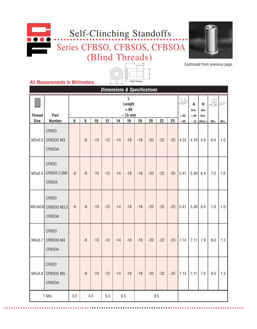
Dimensions & SpecificationsAll Measurements In Millimeters.
Continued from previous page.
6 8 10 12 14 16 18 20 22 25
-8 -10 -12 -14 -16 -18 -20 -22 -25
-6 -8 -10 -12 -14 -16 -18 -20 -22 -25
-6 -8 -10 -12 -14 -16 -18 -20 -22 -25
-8 -10 -12 -14 -16 -18 -20 -22 -25
-8 -10 -12 -14 -16 -18 -20 -22 -25
H
LT
A
Blind Threads
T Min. 3.2 4.0 5.0 6.5 9.5
CFBSO
CFBSOS M3
CFBSOA
CFBSO
CFBSOS 3.5M3
CFBSOA
CFBSO
CFBSOS M3.5
CFBSOA
CFBSO
CFBSOS M4
CFBSOA
CFBSO
CFBSOS M5
CFBSOA
Self-Clinching Standoffs
Series CFBSO, CFBSOS, CFBSOA(Blind Threads)
LLength+.05
–.13 mm
A HDim. Hex
Thread Part +.08 +.00 Dim.
Size Number –.00 –.13 (Nom.) Min. Min.
M3x0.5 4.22 4.19 4.8 6.0 1.0
M3x0.5 5.41 5.38 6.4 7.0 1.0
M3.5x0.6 5.41 5.38 6.4 7.0 1.0
M4x0.7 7.14 7.11 7.9 8.0 1.3
M5x0.8 7.14 7.11 7.9 8.0 1.3
071112 Captive_2011_Text_Catalog 12/5/12 8:21 AM Page 72

2011
Punch
Sheet .040 in. (1.0 mm)
Anvil
Standoff
Max. Length of Standoff+.125 in. (3.175mm)
+.004 in. (.1 mm)
RECOMMENDED INSTALLATION PROCEDURE
1. Insert Standoff through hole in sheet into anvil.
2. Apply only sufficient squeezing force between parallelsurfaces of punch an anvil to embed hex head flushin sheet. Avoid excessive pressures.
Continued from previous page.
Sheet Material: .060 in. 5052-H34 Aluminum .060 in. Cold-rolled SteelRec.
Tighten
InstallationPull
InstallationPull Torque
Thread Standoff Force Pushout Torque-out Through Force Pushout Torque-out Through Max.Code Material (lbs.) (lbs.) (in.- lbs.) (lbs.) (lbs.) (lbs.) (in.- lbs.) (lbs.) (in.- lbs.)
Steel 1075 155 10 270 2100 220 18 325 4.7
440 Stainless 1075 155 10 220 2100 220 18 260 3.6Steel
Aluminum 1075 155 10 160 nr nr nr nr 2.7Steel 1680 290 24 300 3200 410 32 375 4.6, 8.6
6440, 632 Stainless 1680 290 24 235 3200 410 32 300 3.6, 6.8Steel
Aluminum 1680 290 24 180 nr nr nr nr 2.7, 5.1
Steel 2350 380 44 560 3900 550 72 690 8.6, 17,30
8632, 832, Stainless 2350 380 44 450 3900 550 72 550 6.8, 13,1032 Steel 24
Aluminum 2350 380 44 340 nr nr nr nr 5.2, 10,17
Sheet Material: 1.5mm 5052-H34 Aluminum 1.5mm Cold-rolled SteelRec.
TightenInstallation Pull Installation Pull Torque
Thread Standoff Force Pushout Torque-out Through Force Pushout Torque-out Through Max.Code Material (kN) (N) (N•m) (N) (kN) (N) (N•m) (N) (N•m)
Steel 4.7 700 1.2 1230 9.6 990 2.1 1450 .5
M3 Stainless 4.7 700 1.2 985 9.6 990 2.1 1150 .4Steel
Aluminum 4.7 700 1.2 740 nr nr nr nr .3Steel 7.4 1310 2.79 1230 14.5 1850 3.9 1450 .5
3.5M3 Stainless 7.4 1310 2.79 1100 14.5 1850 3.9 1150 .4Steel
Aluminum 7.4 1310 2.79 810 nr nr nr nr .3Steel 10.5 1750 5.01 2550 17.6 2460 8.45 3100 1.9, 3.4
M4, M5 Stainless 10.5 1750 5.01 2020 17.6 2460 8.45 2450 1.5, 2.7Steel
Aluminum 10.5 1750 5.01 1525 nr nr nr nr 1.1, 2.1
INCH
(in.
)M
ETRI
C (m
m)
nr = Not recommended.
Installation & Performance Data
Self-Clinching StandoffsSeries CFSO, CFSOS, CFSOA,CFBSO, CFBSOS & CFBSOA
071112 Captive_2011_Text_Catalog 12/5/12 8:21 AM Page 73

CFSOSG & CFSOAG self-grounding standoffs are designed to beinstalled in steel and aluminum chassis to ground PC boards.Projecting teeth assure excellent electrical contact with PCboard circuit and eliminate need for serrated or star washers.
Series Material Finish
CFSOSG 300 Series PassivatedStainless Steel ASTM A380
CFSOAG 7075-T6 NoneAluminum
Thread: Internal 2B ANSI B1.1 (6H, ANSI/ASME B1.13M).Use in: CFSOSG for materials with Rockwell Hardness of B-70
or less.CFSOAG for materials with Rockwell Hardness of B-50or less.
D
Thread Part Numbers +.000 +.003
Size Stainless Aluminum .125 .187 .250 .312 .375 .437 .500 -.005 –.000 Min.
#4-40 CFSOSG6440 CFSOAG6440 -4† -6 -8 -10 -12 -14 -16 .250 .212 .213 .27
#6-32 CFSOSG8632 CFSOAG8632 -4† -6† -8 -10 -12 -14 -16 .312 .280 .281 .31
Thread Part Numbers +.00 +.08
Size Stainless Aluminum 3 4 6 8 10 12 14 -.13 –.00 Min.
M3x0.5 CFSOSG3.5M3 CFSOAG3.5M3 -3 -4 -6 -8 -10 -12 -14 6.4 5.38 5.4 6.86
Dimensions & Specifications
INCH
(in.
)M
ETRI
C (m
m)
INCH
(in.
)M
ETRI
C (m
m)
Installation & Performance Data
5052-H34 Aluminum
Thread Installation Torque-Size Min. Force (lbs.) Pushout (lbs.) out (in.-lbs.)
#4-40 .040 1500-2000 290 24
#6-32 .050 1500-2000 380 44
Thread Installation Torque-Size Min. Force (kN) Pushout (N) out (N•m)M3 1.0 8 1290 2.7
GrippingTeeth
D
L
F
† Not stocked, available on special order.
D
Self-Grounding Standoffs
Series CFSOSG & CFSOAG
FHexDim.(Nom.)
FHexDim.(Nom.)
LLength
+.010 -.000 in.
LLength
+.25 - .00 mm
071112 Captive_2011_Text_Catalog 12/5/12 8:21 AM Page 74

2011
Self-Clinching StandoffsSeries CF40 & CF40S(Miniature Standoff)
All Measurements In Inches.
All Measurements In Millimeters.
Dimensions & Specifications
Dimensions & Specifications
Series Material Finish
CF4O Heat-treated Zinc* YellowCarbon Steel
CF4OS 300 Series PassivatedStainless Steel ASTM A380
*See Finish Spec. on Page 6.Thread: Internal 2B ANSI B1.1 (6H, ANSI/ASME B1.13M).Use in: CF40 for Material with HRB-80 or less.
CF40S for Material with HRB-70 or less.
Part Number Structure:CF40 - 440 - .250
Length CodeThread CodeSeries
CF40 & CF40S MIniature Standoffs aredesigned to be used in limited spaceapplications. They are ideal for securing D-subconnectors to enclosure backplanes andprovide a flush mounting surface for RFI/EMIgaskets.
Thread Size
Part NumberL
Length+.002
-.005 in.+.003-.000
ADim.Max.
HDim.
(Nom.) Min. Min.SteelStainless
Steel
#4-40 CF40-440 CF40S-440 -.250 -.275 .166 .165 .194 .126 .037-.250
Thread Size
Part NumberL
Length+.05
-.13mm+.08-.00
ADim.Max.
HDim.
(Nom.) Min. Min.SteelStainless
Steel
M3 CF40-M3 CF40S-M3 -6.35 -7 4.22 4.2 4.92 3.2 .94-6.35
071112 Captive_2011_Text_Catalog 12/5/12 8:21 AM Page 75

Sheet Material: .040 in. Cold-rolled Steel Sheet Material: .040 in. 5052-H34 Aluminum
ThreadCode Material
InstallationForce(lbs.)
Pushout(lbs.)
Torque-out(in.-lbs.)
Rec.Tightening
TorqueMax.
(in.-lbs.)ThreadCode Material
InstallationForce(lbs.)
Pushout(lbs.)
Torque-out(in.-lbs.)
Rec.Tightening
TorqueMax.
(in.-lbs.)
440Steel 1300 70 9 3.8
440Steel 1000 45 9 3.8
StainlessSteel 1300 70 9 3.8 Stainless
Steel 1000 45 9 3.8
Sheet Material: 1mm Cold-rolled Steel Sheet Material: 1mm 5052-H34 Aluminum
ThreadCode Material
InstallationForce(kN)
Pushout(N)
Torque-out(N•m)
Rec.Tightening
TorqueMax.(N•m)
ThreadCode Material
InstallationForce(kN)
Pushout(N)
Torque-out(N•m)
Rec.Tightening
TorqueMax.(N•m)
M3Steel 5.8 330 1.0 .44
M3Steel 4.5 220 1.0 .44
StainlessSteel 5.8 330 1.0 .44 Stainless
Steel 4.5 220 1.0 .44
Self-Clinching StandoffsSeries CF40 & CF40S(Miniature Standoff)
Continued from previous page.
Installation & Performance Data
INCH
(in.
)M
ETRI
C (m
m)
071112 Captive_2011_Text_Catalog 12/5/12 8:21 AM Page 76
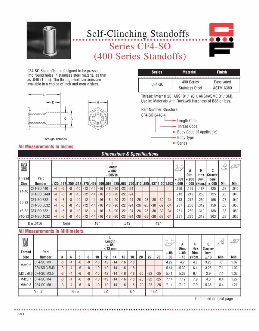
2011
Series CF4-SO(400 Series Standoffs)
Self-Clinching Standoffs
All Measurements In Inches.
All Measurements In Millimeters.
Dimensions & Specifications
ThreadSize
PartNumber
LLength+.002
-.005 in.+.003-.000
ADim.+.000-.005
HHexDim.
(Nom.)
CCounter-
bore±.005 Min. Min..125 .187 .250 .312 .375 .437 .500 .562 .625 .687 .750 .812 .875 .937 1.00 1.062
#4-40CF4-SO 440 -4 -6 -8 -10 -12 -14 -16 -18 -20 -22 -24 .166 .165 .187 .125 .23 .040
CF4-SO 6440 -4 -6 -8 -10 -12 -14 -16 -18 -20 -22 -24 .213 .212 .250 .125 .28 .040
#6-32CF4-SO 632 -4 -6 -8 -10 -12 -14 -16 -18 -20 -22 -24 -26 -28 -30 -32 -34 .213 .212 .250 .156 .28 .040
CF4-SO 8632 -4 -6 -8 -10 -12 -14 -16 -18 -20 -22 -24 -26 -28 -30 -32 -34 .281 .280 .312 .156 .33 .050
#8-32 CF4-SO 832 -4 -6 -8 -10 -12 -14 -16 -18 -20 -22 -24 -26 -28 -30 -32 -34 .281 .280 .312 .188 .33 .050
#10-32 CF4-SO 1032 -4 -6 -8 -10 -12 -14 -16 -18 -20 -22 -24 -26 -28 -30 -32 -34 .281 .280 .312 .203 .33 .050
D ± .0156 None .187 .312 .437
ThreadSize
PartNumber
LLength+.05
-.13 mm+.08-.00
ADim.+.00-.13
HHexDim.
(Nom.)
CCounter-
bore±.13 Min. Min.3 4 6 8 10 12 14 16 18 20 22 25
M3x0.5CF4-SO M3 -3 -4 -6 -8 -10 -12 -14 -16 -18 4.22 4.2 4.8 3.25 6 1.02
CF4-SO 3.5M3 -3 -4 -6 -8 -10 -12 -14 -16 -18 5.41 5.39 6.4 3.25 7.1 1.02
M3.5x0.6 CF4-SO M3.5 -3 -4 -6 -8 -10 -12 -14 -16 -18 -20 -22 -25 5.41 5.39 6.4 3.9 7.1 1.02
M4x0.7 CF4-SO M4 -3 -4 -6 -8 -10 -12 -14 -16 -18 -20 -22 -25 7.14 7.12 7.9 4.8 8.4 1.27
M5x0.8 CF4-SO M5 -3 -4 -6 -8 -10 -12 -14 -16 -18 -20 -22 -25 7.14 7.12 7.9 5.35 8.4 1.27
D ± .4 None 4.0 8.0 11.0
Continued on next page.
CF4-SO Standoffs are designed to be pressedinto round holes in stainless steel material as thinas .040 (1mm). The through-hole versions areavailable in a choice of inch and metric sizes.
Series Material Finish
CF4-SO 400 Series PassivatedStainless Steel ASTM A380
Thread: Internal 2B, ANSI B1.1 (6H, ANSI/ASME B1.13M).Use in: Materials with Rockwell Hardness of B88 or less.
Part Number Structure:CF4-SO 6440-4
Length CodeThread CodeBody Code (if Applicable)Body TypeSeries
071112 Captive_2011_Text_Catalog 12/5/12 8:21 AM Page 77

Self-Clinching StandoffsSeries CF4-BSO
(400 Series Blind Standoffs)Continued from previous page.
All Measurements In Inches.
All Measurements In Millimeters.
Dimensions & Specifications
ThreadSize
PartNumber
LLength+.002
-.005 in.+.003-.000
ADim.+.000-.005
HHexDim.
(Nom.) Min. Min..312 .375 .437 .500 .562 .625 .687 .750 .812 .875 .937 1.00 1.062
#4-40CF4-BSO 440 -10 -12 -14 -16 -18 -20 -22 -24 .166 .165 .187 .23 .040CF4-BSO 6440 -10 -12 -14 -16 -18 -20 -22 -24 -26 -28 -30 -32 -34 .213 .212 .250 .28 .040
#6-32CF4-BSO 632 -10 -12 -14 -16 -18 -20 -22 -24 -26 -28 -30 -32 -34 .213 .212 .250 .28 .040CF4-BSO 8632 -10 -12 -14 -16 -18 -20 -22 -24 -26 -28 -30 -32 -34 .281 .280 .312 .33 .050
#8-32 CF4-BSO 832 -10 -12 -14 -16 -18 -20 -22 -24 -26 -28 -30 -32 -34 .281 .280 .312 .33 .050#10-32 CF4-BSO 1032 -10 -12 -14 -16 -18 -20 -22 -24 -26 -28 -30 -32 -34 .281 .280 .312 .33 .050
T Dim. Min. .156 .187 .250 .375
ThreadSize
PartNumber
LLength+.05
-.13 mm+.08-.00
ADim.+.00-.13
HHexDim.
(Nom.) Min. Min.6 8 10 12 14 16 18 20 22 25
M3x0.5CF4-BSO M3 -6 -8 -10 12 -14 -16 -18 4.22 4.2 4.8 6 1.02CF4-BSO 3.5M3 -6 -8 -10 12 -14 -16 -18 5.41 5.39 6.4 7.1 1.02
M3.5x0.6 CF4-BSO M3.5 -6 -8 -10 12 -14 -16 -18 -20 -22 -25 5.41 5.39 6.4 7.1 1.02M4x0.7 CF4-BSO M4 -6 -8 -10 12 -14 -16 -18 -20 -22 -25 7.14 7.12 7.9 8.4 1.27M5x0.8 CF4-BSO M5 -6 -8 -10 12 -14 -16 -18 -20 -22 -25 7.14 7.12 7.9 8.4 1.27
T Dim. Min. 3.2 4.0 5.0 6.5 9.5
CF4-BSO Standoffs are designed to be pressedinto round holes in stainless steel material as thinas .040 (1mm). The blind-hole versions areavailable in a choice of inch and metric sizes.
Series Material Finish
CF4-BSO 400 Series PassivatedStainless Steel ASTM A380
Thread: Internal 2B, ANSI B1.1 (6H, ANSI/ASME B1.13M).
Use in: Materials with Rockwell Hardness of B88 or less.
Part Number Structure:CF4-BSO 6440-10
Length CodeThread CodeBody CodeBody TypeSeries
071112 Captive_2011_Text_Catalog 12/5/12 8:21 AM Page 78

Sheet Material: .050 in. 300 Series Stainless Steel
Thread Code
InstallationForce(lbs.)
Pushout(lbs.)
Torque-out(in.-lbs.)
Pull Through(lbs.)
Rec.Tightening
Torque Max.(in.-lbs.)
440 5500 330 16 595 4.756440 9500 640 29 675 4.75632 9500 640 29 675 8.758632 10500 895 70 1390 8.75832 10500 895 70 1515 181032 10500 895 70 1365 32
Sheet Material: 1.3mm 300 Series Stainless Steel
Thread Code
InstallationForce(kN)
Pushout(N)
Torque-out(N•m)
Pull Through(N)
Rec.Tightening
Torque Max.(N•m)
M3 24.5 1467 1.81 2645 .553.5 M3 42.3 2847 3.00 3000 .55M3.5 42.3 2847 3.00 3000 .91M4 46.7 3981 8.85 6450 2M5 46.7 3981 8.85 6070 3.6
2011
Continued from previous page.
Self-Clinching StandoffsSeries CF4-SO, CF4-BSO
(400 Series Standoffs)
Dimensions & Specifications
RECOMMENDED INSTALLATION PROCEDURE
1. Insert Standoff through hole in sheet into anvil.
2. Apply sufficient squeezing force between parallelsurfaces of punch an anvil to embed hex head flushin sheet. Avoid excessive pressure.
INCH
(in.
)M
ETRI
C (m
m)
071112 Captive_2011_Text_Catalog 12/5/12 8:21 AM Page 79
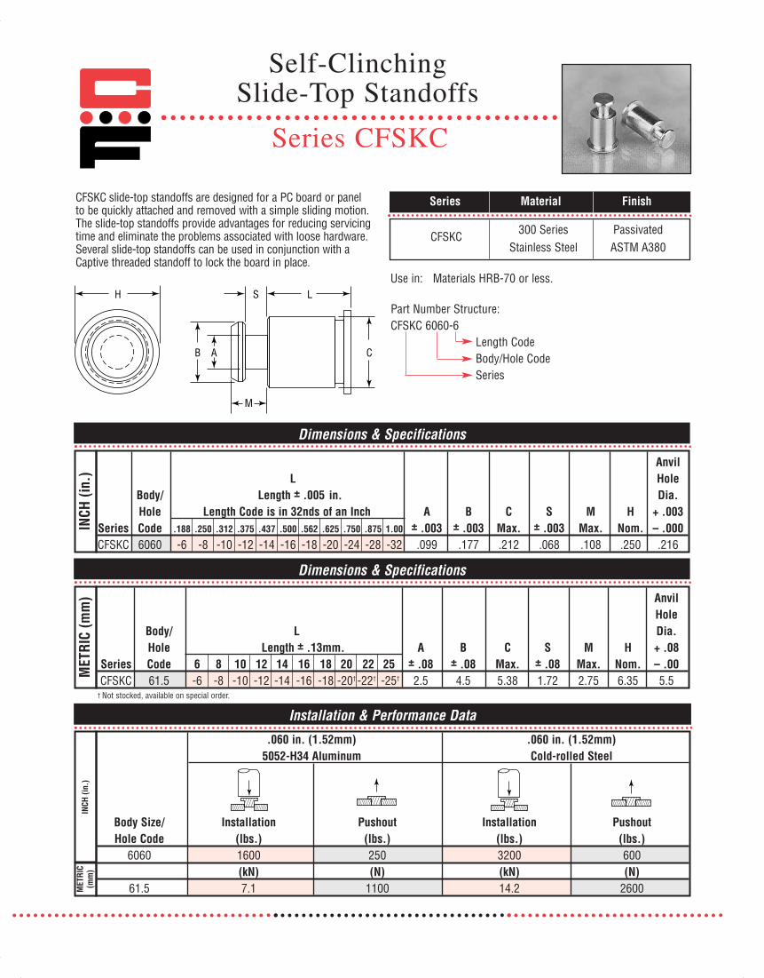
H
M
S L
B A C
Dimensions & Specifications
Dimensions & Specifications
AnvilL Hole
Body/ Length ± .005 Dia.Hole Length Code is in 32nds of an Inch A B C S M H + .003
Series Code .188 .250 .312 .375 .437 .500 .562 .625 .750 .875 1.00 ± .003 ± .003 Max. ± .003 Max. Nom. – .000CFSKC 6060 -6 -8 -10 -12 -14 -16 -18 -20 -24 -28 -32 .099 .177 .212 .068 .108 .250 .216
AnvilHole
Body/ L Dia.Hole Length ± .13mm. A B C S M H + .08
Series Code 6 8 10 12 14 16 18 20 22 25 ± .08 ± .08 Max. ± .08 Max. Nom. – .00CFSKC 61.5 -6 -8 -10 -12 -14 -16 -18 -20† -22† -25† 2.5 4.5 5.38 1.72 2.75 6.35 5.5
INCH
(in.
)M
ETRI
C (m
m)
CFSKC slide-top standoffs are designed for a PC board or panel to be quickly attached and removed with a simple sliding motion.The slide-top standoffs provide advantages for reducing servicingtime and eliminate the problems associated with loose hardware.Several slide-top standoffs can be used in conjunction with aCaptive threaded standoff to lock the board in place.
Series Material Finish
CFSKC 300 Series PassivatedStainless Steel ASTM A380
Use in: Materials HRB-70 or less.
Part Number Structure:CFSKC 6060-6
Length CodeBody/Hole CodeSeries
† Not stocked, available on special order.
Installation & Performance Data
INCH
(in.
)M
ETRI
C(m
m)
.060 in. (1.52mm) .060 in. (1.52mm) 5052-H34 Aluminum Cold-rolled Steel
Body Size/ Installation Pushout Installation PushoutHole Code (lbs.) (lbs.) (lbs.) (lbs.)
6060 1600 250 3200 600(kN) (N) (kN) (N)
61.5 7.1 1100 14.2 2600
in.
Self-ClinchingSlide-Top Standoffs
Series CFSKC
071112 Captive_2011_Text_Catalog 12/5/12 8:21 AM Page 80
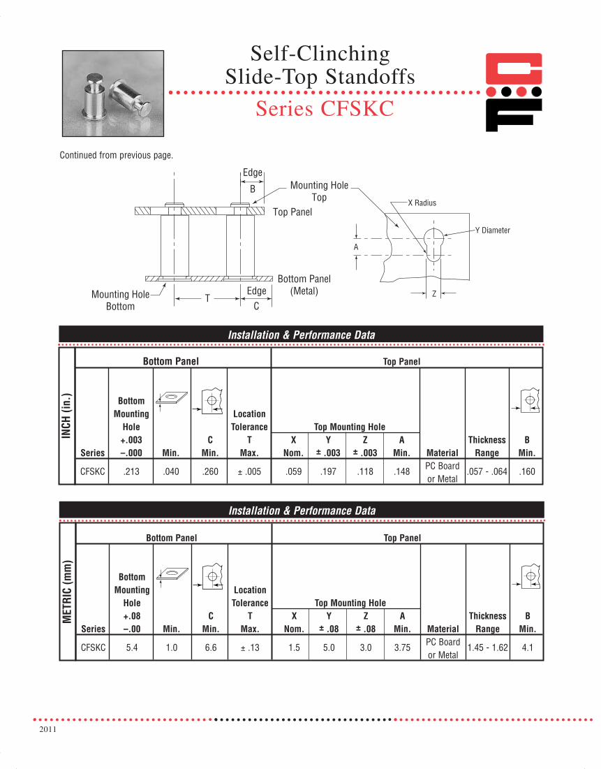
2011
A
X Radius
Y Diameter
Z
Mounting HoleTop
Mounting HoleBottom
Top Panel
Bottom Panel(Metal)
Edge
Edge
B
CT
Continued from previous page.
Installation & Performance Data
INCH
(in.
)
Bottom Panel Top Panel
BottomMounting Location
Hole Tolerance Top Mounting Hole+.003 C T X Y Z A Thickness B
Series –.000 Min. Min. Max. Nom. ± .003 ± .003 Min. Material Range Min.
CFSKC .213 .040 .260 ± .005 .059 .197 .118 .148 PC Board .057 - .064 .160or Metal
Installation & Performance Data
MET
RIC
(mm
)
Bottom Panel Top Panel
BottomMounting Location
Hole Tolerance Top Mounting Hole+.08 C T X Y Z A Thickness B
Series –.00 Min. Min. Max. Nom. ± .08 ± .08 Min. Material Range Min.
CFSKC 5.4 1.0 6.6 ± .13 1.5 5.0 3.0 3.75 PC Board 1.45 - 1.62 4.1or Metal
Self-ClinchingSlide-Top Standoffs
Series CFSKC
071112 Captive_2011_Text_Catalog 12/5/12 8:21 AM Page 81

Male Self-ClinchingStandoffs
Series CFMS
CFMS Standoffs provide a permanently captivatedfastener with a reusable threaded post to mount PCboards and other components in electronic displays.The unique part is available in heat-treated and zincplated steel or passivated stainless steel and can beinstalled into metal sheets as thin as.050 in (1.27 mm) thick.
Series Material Finish
Thread: External 2A, ANSI B1.1 (6g, ANSI/ASME B1.13M).*Use in: CFMS for materials with HRB-80 or less.
CFMSS for materials with HRB-70 or less.
Part Number Structure:CFMS 632 - 6
Length CodeThread CodeSeries
ThreadSize
Part NumberThreadCode
LLength ±.015 in.
Min.+.003-.000
T±.005
D±.005
CMax.Steel Stainless .375 .437 .500
#6-32 CFMS CFMSS 632 -6 -7 -8 .050 .250 .312 .303 .249#6-32 CFMS CFMSS 8632 -6 -7 -8 .050 .281 .375 .334 .280
Dimensions & Specifications
INCH
(in.
)
ThreadSize
Part NumberThreadCode
LLength ±.4 mm
Min.+.08-.00
T±.13
D±.13
CMax.Steel Stainless 8 10 12
M3.5x0.6 CFMS CFMSS M3.5 -8 -10 -12 1.27 6.35 7.92 7.70 6.32M3.5x0.6 CFMS CFMSS 4M3.5 -8 -10 -12 1.27 7.14 9.52 8.49 7.12
Dimensions & Specifications
MET
RIC
(mm
)
Note: All items subject to minimum order
*See Note 3 on Page 6 for Gauging Spec.
CFMS Heat-treatedCarbon Steel
Zinc Clear perASTM B633
CFMSS 300 SeriesStainless Steel
PassivatedASTM A380
071112 Captive_2011_Text_Catalog 12/5/12 8:21 AM Page 82

2011
Dimensions & Specifications
B+.004 -.003 C HThru-Hole Part +.003 +.000 Hex
Diameter Number .125 .1875 .250 .3125 .375 .4375 .500 .5625 .625 .6875 .750 –.000 –.005 Dim. Min. Min.
CFSO.116 CFSOS4116 -4 -6 -8 -10 -12 -14 -16 -18 -20 -22 -24 .166 .165 .187 .23 .040
CFSOACFSO
.116 CFSOS 6116 -4 -6 -8 -10 -12 -14 -16 -18 -20 -22 -24 .213 .212 .250 .27 .040CFSOACFSO
.143 CFSOS 6143 -4 -6 -8 -10 -12 -14 -16 -18 -20 -22 -24 .213 .212 .250 .27 .040CFSOACFSO
.143 CFSOS 8143 -4 -6 -8 -10 -12 -14 -16 -18 -20 -22 -24 .281 .280 .312 .31 .050CFSOACFSO
.169 CFSOS 8169 -4 -6 -8 -10 -12 -14 -16 -18 -20 -22 -24 .281 .280 .312 .31 .050CFSOACFSO
.194 CFSOS 8194 -4 -6 -8 -10 -12 -14 -16 -18 -20 -22 -24 .281 .280 .312 .31 .050CFSOA
CFSO self-clinching standoffs are designed for quick, simpleinstallation with any standard press into a drilled or punchedhole, and become permanently attached to the thin sheet metalmaterial. They are primarily used to provide spacing of multi-panel assemblies. The unthreaded hole allows threaded studsto pass directly through the spacer to lower areas.
HL
B C
All Measurements In Inches.
Series Material Finish
Use in: CFSO for materials with Rockwell Hardness of B-80 or less.CFSOS for materials with Rockwell Hardness of B-70 or less.CFSOA for materials with Rockwell Hardness of B-50 or less.
*See Finish Spec. on Page 6.
Part Number Structure:CFSO 4116-4
Length CodeBody/Hole CodeSeries
LLength+.002
–.005 in.
Unthreaded Thru-Hole Standoffs
Series CFSO, CFSOS & CFSOA
CFSO Heat-treatedCarbon Steel Zinc* Clear
CFSOS 300 SeriesStainless Steel
PassivatedASTM A380
CFSOA 7075-T6 Aluminum None
071112 Captive_2011_Text_Catalog 12/5/12 8:21 AM Page 83
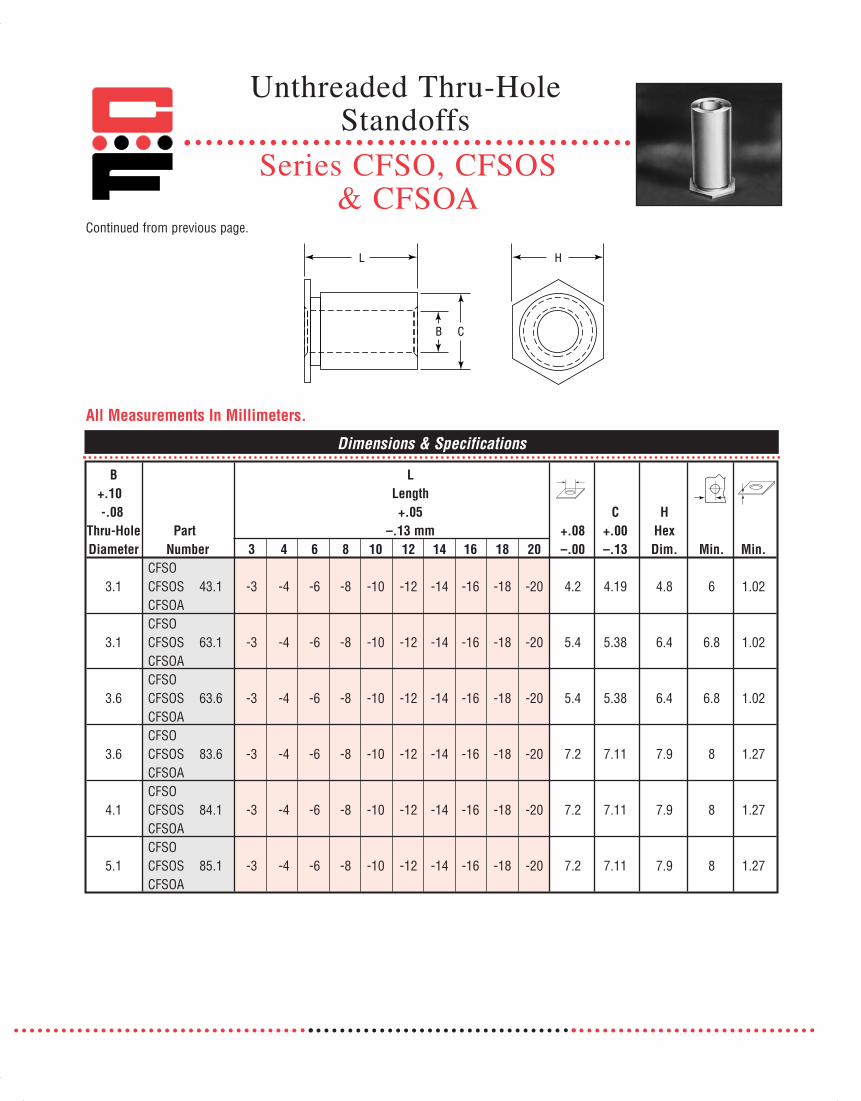
Continued from previous page.
Dimensions & Specifications
B+.10-.08 C H
Thru-Hole Part +.08 +.00 HexDiameter Number 3 4 6 8 10 12 14 16 18 20 –.00 –.13 Dim. Min. Min.
CFSO3.1 CFSOS 43.1 -3 -4 -6 -8 -10 -12 -14 -16 -18 -20 4.2 4.19 4.8 6 1.02
CFSOACFSO
3.1 CFSOS 63.1 -3 -4 -6 -8 -10 -12 -14 -16 -18 -20 5.4 5.38 6.4 6.8 1.02CFSOACFSO
3.6 CFSOS 63.6 -3 -4 -6 -8 -10 -12 -14 -16 -18 -20 5.4 5.38 6.4 6.8 1.02CFSOACFSO
3.6 CFSOS 83.6 -3 -4 -6 -8 -10 -12 -14 -16 -18 -20 7.2 7.11 7.9 8 1.27CFSOACFSO
4.1 CFSOS 84.1 -3 -4 -6 -8 -10 -12 -14 -16 -18 -20 7.2 7.11 7.9 8 1.27CFSOACFSO
5.1 CFSOS 85.1 -3 -4 -6 -8 -10 -12 -14 -16 -18 -20 7.2 7.11 7.9 8 1.27CFSOA
All Measurements In Millimeters.
HL
B C
LLength+.05
–.13 mm
Unthreaded Thru-Hole Standoffs
Series CFSO, CFSOS & CFSOA
071112 Captive_2011_Text_Catalog 12/5/12 8:21 AM Page 84
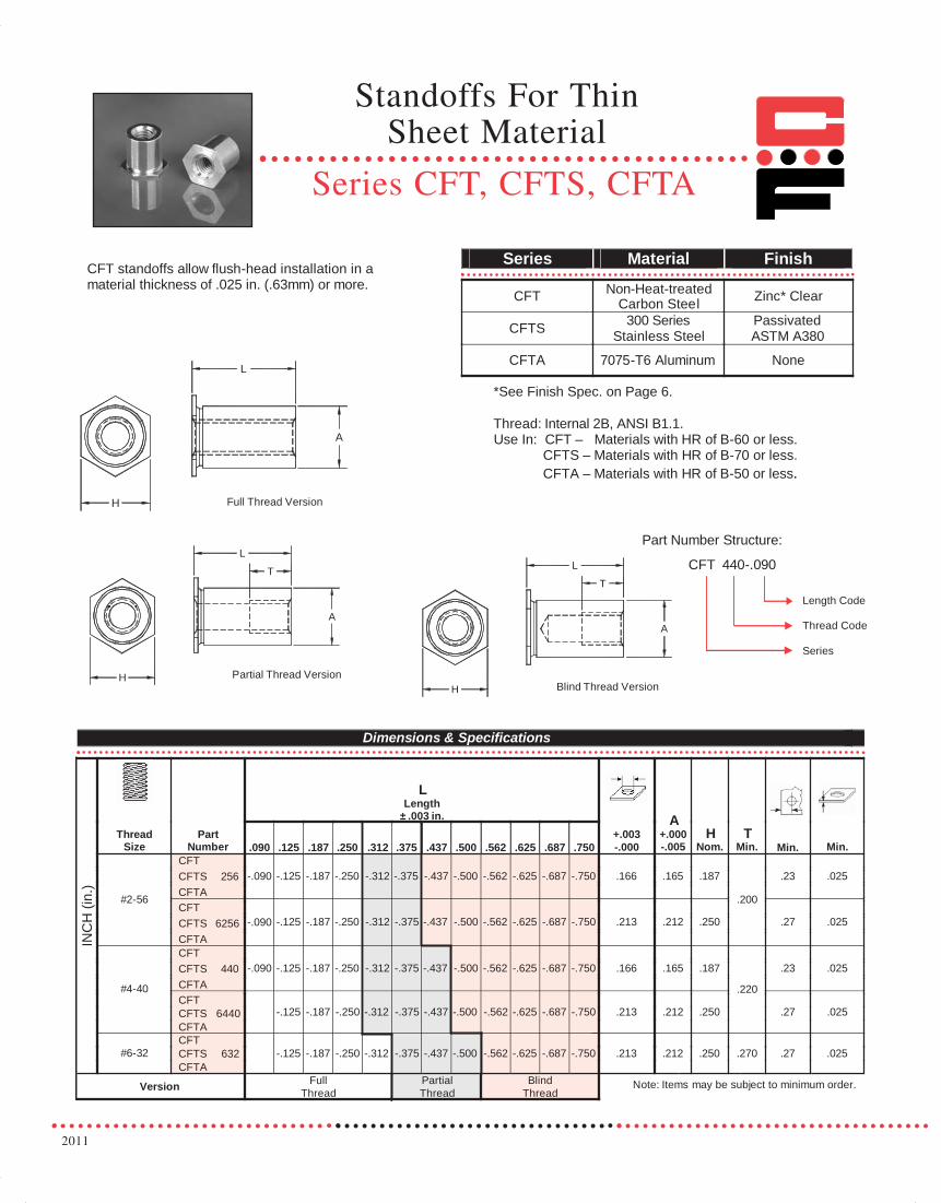
2011
H
L
A
T
Thread: Internal 2B, ANSI B1.1.Use In: CFT – Materials with HR of B-60 or less.
CFTS – Materials with HR of B-70 or less.CFTA – Materials with HR of B-50 or less.
Series Material Finish
CFT Non-Heat-treatedCarbon Steel Zinc* Clear
CFTS 300 SeriesStainless Steel
PassivatedASTM A380
CFTA 7075-T6 Aluminum None
Length Code
Thread Code
Series
Dimensions & Specifications
LLength
± .003 in.Thread
SizePart
Number .090 .125 .187 .250 .312 .375 .437 .500 .562 .625 .687 .750+.003-.000
A+.000-.005
HNom.
TMin. Min. Min.
CFTCFTS 256
#2-56 CFTA-.090 -.125 -.187 -.250 -.312 -.375 -.437 -.500 -.562 -.625 -.687 -.750 .166 .165 .187 .23 .025
CFTCFTS 6256CFTA
-.090 -.125 -.187 -.250 -.312 -.375 -.437 -.500 -.562 -.625 -.687 -.750 .213 .212 .250
.200
.27 .025
CFTCFTS 440
#4-40 CFTA-.090 -.125 -.187 -.250 -.312 -.375 -.437 -.500 -.562 -.625 -.687 -.750 .166 .165 .187 .23 .025
CFTCFTS 6440CFTA
-.125 -.187 -.250 -.312 -.375 -.437 -.500 -.562 -.625 -.687 -.750 .213 .212 .250
.220
.27 .025
CFTCFTS 632
INC
H (i
n.)
#6-32CFTA
-.125 -.187 -.250 -.312 -.375 -.437 -.500 -.562 -.625 -.687 -.750 .213 .212 .250 .270 .27 .025
Version FullThread
PartialThread
BlindThread
CFT standoffs allow flush-head installation in a material thickness of .025 in. (.63mm) or more.
Note: Items may be subject to minimum order.
CFT 440-.090
Part Number Structure:
Blind Thread Version
H
L
A
Full Thread Version
H
A
T
L
Partial Thread Version
*See Finish Spec. on Page 6.
Standoffs For Thin Sheet Material
Series CFT, CFTS, CFTA
071112 Captive_2011_Text_Catalog 12/5/12 8:21 AM Page 85

H
L
A
T
Thread: Internal 6H, ANSI/ASME B1.13M.Use In: CFT – Materials with HR of B-60 or less.
CFTS – Materials with HR of B-70 or less. CFTA – Materials with HR of B-50 or less.
Series Material Finish
CFT Non-Heat-treatedCarbon Steel Zinc* Clear
CFTS 300 SeriesStainless Steel
PassivatedASTM A380
CFTA 7075-T6 Aluminum None
Length Code
Thread Code
Series
Dimensions & Specifications
LLength
±.08 mm
ThreadSize
PartNumber 2.00 3.00 4.00 6.00 8.00 10.00 12.00 14.00 16.00 18.00 19.00
+.08 -.00
A +.00 -.13
HNom.
TMin. Min. Min.
CFTCFTS M2.5CFTA
-200 -300 -400 -600 -800 -1000 -1200 -1400 -1600 -1800 -1900 4.2 4.19 4.8 5.8 .63
CFTCFTS 6M2.5 CFTA
-200 -300 -400 -600 -800 -1000 -1200 -1400 -1600 -1800 -1900 5.4 5.38 6.45.2
7.1 .63
CFTCFTS M3CFTA
-200 -300 -400 -600 -800 -1000 -1200 -1400 -1600 -1800 -1900 4.2 4.19 4.8 5.8 .63
CFTCFTS 6M3CFTA
-200 -300 -400 -600 -800 -1000 -1200 -1400 -1600 -1800 -1900 5.4 5.38 6.4
6.2
7.1 .63
CFTCFTS M3.5CFTA
-300 -400 -600 -800 -1000 -1200 -1400 -1600 -1800 -1900 5.4 5.38 6.4 7.0 7.1 .63
Version FullThread
PartialThread
Blind Thread
CFT standoffs allow flush-head installation in a material thickness of .025 in. (.63mm) or more.
Note: Items may be subject to minimum order.
CFT M2.5-200
Part Number Structure:
Blind Thread VersionPartial Thread Version
Full Thread Version
H
L
A
H
A
T
L
M2.5x0.45
M3.5x0.6
M3x0.5
*See Finish Spec. on Page 6.
MET
RIC
(mm
)Standoffs For Thin
Sheet Material
Series CFT, CFTS & CFTA
Continued from previous page.
071112 Captive_2011_Text_Catalog 12/5/12 8:21 AM Page 86

2011
Continued from previous page.
Installation & Performance Data
.165 in. (4.19mm)
2000 8.9 98 435 8 .901500 6.7 68 302 5 .56- - - - - -
2500 11.1 148 658 14 1.6.212 in. (5.38 mm)
CFTCFTSCFTA
CFTCFTSCFTA
1800 8 88 391 10 1.13- - - - - -
Sheet Material.025 in. (.64mm) 5052-H-34 Aluminium .025 in. (.64mm) Cold-rolled Steel
A Installation Pushout Torque-out Installation Pushout Torque-outDim. Series lbs. kN lbs. N in.-lbs. N•m lbs. kN lbs. N in.-lbs. N•m
120°
Y
L
X
ANVIL
PUNCH
1. Prepare the required size hole in thebase material by punching or drilling.Do not deburr hole.
2. Place standoff through hole inmaterial and into installation anviland squeeze into place using a shoppress with flat punch.
3. Apply a sufficient force to seat thehex head flush into the basematerial.
4. Use chamfered anvil shown for sheetthickness of .025 to .032 in. (.63 to.81 mm) for sheets over .032 (.81mm) The special anvil is notrequired.
The installation and performance data listed are nominal when all specifications are adhered to. Changes in sheet hardness and mounting hole tolerance will affect performance. Therefore, we recommend testing the product in your application to determine actual results. Samples are available upon request.
Installation
StandoffA
Dimension Inches mm Inches mm.165 in./4.19mm
.212 in./5.38mm
.167 - .170
.213 - .216
4.24 - 4.32
5.41 - 5.49
.187 - .194
.250 - .257
4.75 - 4.93
6.35 - 6.53
Y XAnvil Dimensions
Standoffs For Thin Sheet Material
Series CFT, CFTS, CFTA
071112 Captive_2011_Text_Catalog 12/5/12 8:21 AM Page 87

CB
LD
H
CFSSA, CFSSS & CFSSC spring-top standoffs are designed for permanent installation into sheet metal by pressing into a prepared hole. The spring-action post provides quick attach-ment and removal with a simple snap eliminating the problemsassociated with loose hardware.
Series Material Finish
CFSSA 7075-T6 PlainAluminum
CFSSS Carbon Steel Zinc* Clear
CFSSC 400 Series PassivatedStainless Steel ASTM A380
*See Finish Spec. on Page 6.
Part Number Structure:CFSSA 156-8
Length CodeHole DiameterSeries
Use in: CFSSA – Cold-rolled Steel HRB-50 or less.CFSSS – Cold-rolled Steel HRB-60 or less.CFSSC – Cold-rolled Steel HRB-70 or less.
Continued on next page.
Dimensions & Specifications
Top Panel
Mounting Hole Length ± .005 in.Diameter (Length Code in 32nds of an inch) B C D H
Series Code .250 .312 .375 .437 .500 .562 .625 .750 .875 1.000 ± .005 Max. ± .005 ± .005CFSSACFSSC 156 -8 -10 -12 -14 -16 -18 -20 -24 -28 -32 .188 .212 .141 .250CFSSSIN
CH (i
n.)
Dimensions & Specifications
Top Panel
Mounting Hole Length ± .13 mmDiameter (Length Code is in millimeters) B C D H
Series Code 8 10 12 14 16 18 20 22 25 ± .13 Max. ± .13 ± .13CFSSACFSSC 4MM -8 -10 -12 -14 -16 -18 -20 -22 -25 4.77 5.38 3.58 6.35CFSSSM
ETRI
C (m
m)
L
L
Spring-Top Standoffs
Series CFSSA, CFSSS& CFSSC
071112 Captive_2011_Text_Catalog 12/5/12 8:21 AM Page 88
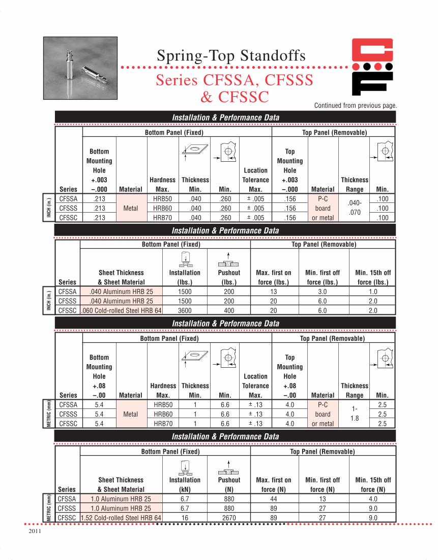
2011
Installation & Performance Data
Bottom Panel (Fixed) Top Panel (Removable)
Bottom TopMounting Mounting
Hole Location Hole+.003 Hardness Thickness Tolerance +.003 Thickness
Series –.000 Material Max. Min. Min. Max. –.000 Material Range Min.CFSSA .213 HRB50 .040 .260 ± .005 .156 P-C .040- .100CFSSS .213 Metal HRB60 .040 .260 ± .005 .156 board .070 .100CFSSC .213 HRB70 .040 .260 ± .005 .156 or metal .100IN
CH (i
n.)
Installation & Performance Data
Bottom Panel (Fixed) Top Panel (Removable)
Bottom TopMounting Mounting
Hole Location Hole+.08 Hardness Thickness Tolerance +.08 Thickness
Series –.00 Material Max. Min. Min. Max. –.00 Material Range Min.CFSSA 5.4 HRB50 1 6.6 ± .13 4.0 P-C 1- 2.5CFSSS 5.4 Metal HRB60 1 6.6 ± .13 4.0 board 1.8 2.5CFSSC 5.4 HRB70 1 6.6 ± .13 4.0 or metal 2.5M
ETRI
C (m
m)
Continued from previous page.
Installation & Performance Data
Bottom Panel (Fixed) Top Panel (Removable)
Sheet Thickness Installation Pushout Max. first on Min. first off Min. 15th offSeries & Sheet Material (lbs.) (lbs.) force (lbs.) force (lbs.) force (lbs.)CFSSA .040 Aluminum HRB 25 1500 200 13 3.0 1.0CFSSS .040 Aluminum HRB 25 1500 200 20 6.0 2.0CFSSC .060 Cold-rolled Steel HRB 64 3600 400 20 6.0 2.0IN
CH (i
n.)
Installation & Performance Data
Bottom Panel (Fixed) Top Panel (Removable)
Sheet Thickness Installation Pushout Max. first on Min. first off Min. 15th offSeries & Sheet Material (kN) (N) force (N) force (N) force (N)CFSSA 1.0 Aluminum HRB 25 6.7 880 44 13 4.0CFSSS 1.0 Aluminum HRB 25 6.7 880 89 27 9.0CFSSC 1.52 Cold-rolled Steel HRB 64 16 2670 89 27 9.0M
ETRI
C (m
m)
Spring-Top Standoffs
Series CFSSA, CFSSS& CFSSC
071112 Captive_2011_Text_Catalog 12/5/12 8:21 AM Page 89

Self-ClinchingConcealed-Head Standoffs
CFHS concealed head standoffs allow permanent mounting inthin metal sheets, using a hollow punch and solid anvil. Thestandoff is pressed permanently into a blind milled hole, withno marring of the exterior surface.
300 Series PassivatedCFHS Stainless Steel ASTM A380
Series Material Finish
Thread: Internal 2B, ANSI B1.1 (6H ANSI/ASME B1.13M)Use in: Materials with HRB-70 or less.
Dimensions & Specifications
INCH
(in.
)
CFHS-1-440-4Length CodeThread CodeType CodeSeries
Part Number Structure:
ThreadSize
TypeCode
ThreadCode
LLength
+.002 - .005 (in.) Min.SheetThick-ness
BlindMountingHole Dia.
+.003-.000
Min.Depth
OfBlindHole
TMin.DepthFull
ThreadD
Max.C
Max.A
Max.H
Nom.
Min.
Dist.
Hole C/L
To Edge
.187 .250 .312 .375 .500 .525 .750 1.00
.112-40(#4-40)
CFHS-1 440 3A 4B 5B 6B 8C 10C 12C 16C .062 .213 .043 .188 .041 .165 .212 .250 .188CFHS-2 .093 .075 .072
.138-32(#6-32)
CFHS-1 632 3A 4A 5B 6B 8C 10C 12C 16C .062 .290 .043 .250 .041 .213 .289 .312 .219CFHS-2 .093 .075 .072
.164-32(#8-32)
CFHS-1832† 3A 4A 5B 6B 8C 10C 12C 16C
.062.312
.043.250
.041.245 .311 .344 .250
CFHS-2 .093 .075 .072.190-32(#10-32)
CFHS-11032† 3A 4A 5A 6A 8B 10C 12C 16C
.062.344
.043.375
.041.290 .343 .375 .281
CFHS-2 .093 .075 .072.250-20(1/4-20)
CFHS-2 420† 3A 4A 5A 6A 8B 10B 12C 16C .093 .390 .075 .375 .072 .354 .389 .438 .375
Type CFHS-1 Type CFHS-2
MET
RIC
(mm
)
ThreadSize
TypeCode
ThreadCode
LLength
+.05 - .13 (mm) Min.SheetThick-ness
BlindMountingHole Dia.
+.08-.00
Min.Depth
OfBlindHole
TMin.DepthFull
ThreadD
Max.C
Max.A
Max.H
Nom.
Min.
Dist.
Hole C/L
To Edge
4 6 8 10 12 16 20 25
M3x0.5 CFHS-1 M3 4A 6A8B
10C 12C 16C 20C 25C 1.6 5.41 1.1 5 1.04 4.2 5.39 6.35 4.8CFHS-2 8C 2.4 1.91 1.83
M4x0.7 CFHS-1 M4 4A 6A 8B10B
12C 16C 20C 25C 1.6 7.92 1.1 6.5 1.04 6.23 7.9 8.74 6.4CFHS-2 10C 2.4 1.91 1.83
M5x0.8CFHS-1
M5† 4A 6A 8B 10B 12B 16C 20C 25C1.6
8.741.1
9.61.04
7.37 8.72 9.53 7.2CFHS-2 2.4 1.91 1.83
M6x1 CFHS-2 M6† 4A 6A 8A 10B 12B 16C 20C 25C 2.4 9.9 1.91 9.6 1.83 9 9.89 11.11 9.5
Continued on next page.†Not stocked, available on special order.
Full ThreadA
Partial ThreadB
Blind ThreadC
Series CFHS
071112 Captive_2011_Text_Catalog 12/5/12 8:21 AM Page 90
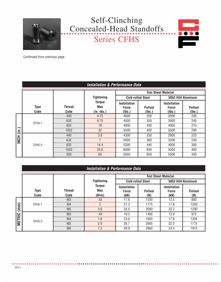
2011
Self-ClinchingConcealed-Head Standoffs
Series CFHS
Installation & Performance Data
INCH
(in.
)
TypeCode
ThreadCode
TighteningTorque
Max(in.-lbs.)
Test Sheet MaterialCold-rolled Steel 5052-H34 Aluminum
InstallationForce(lbs.)
Pullout(lbs.)
InstallationForce(lbs.)
Pullout(lbs.)
CFHS-1
440 4.75 4000 300 2000 200632 8.75 4500 350 3000 240832 18 4800 400 4000 2701032 32 5500 450 5000 290
CFHS-2
440 3.8 4300 330 2900 220632 7 5000 360 3200 240832 14.4 5300 440 4000 3001032 25.6 6000 600 5000 400420 64 6500 650 5500 430
TypeCode
ThreadCode
TighteningTorque
Max(N•m)
Test Sheet MaterialCold-rolled Steel 5052-H34 Aluminum
InstallationForce(kN)
Pullout(N)
InstallationForce(kN)
Pullout(N)
CFHS-1M3 .55 17.8 1330 12.5 890M4 2 21.3 1775 17.8 1200M5 3.6 24.5 2000 22.2 1290
CFHS-2
M3 .44 19.2 1465 12.9 975M4 1.6 23.6 1955 17.8 1335M5 2.9 26.7 2665 22.2 1775M6 7.2 28.9 2860 24.4 1915
Installation & Performance Data
MET
RIC
(mm
)
Continued from previous page.
071112 Captive_2011_Text_Catalog 12/5/12 8:21 AM Page 91

Series CFHSTypical Installation Method
Self-ClinchingConcealed-Head Standoffs
1. Mill a blind hole in material to specified depth.
2. Place fastener into hole in anvil.
3. Place sheet material over head of fastener.
4. Apply a downward squeezing force with punch,
pressing on sheet material until serrated collar of
fastener is flush with surface.
*Depth of blind holes may be greater than minimum, if sheet thickness allows.
Continued from previous page.
Installation Procedure
Anvil ‘D’ Diameter Dimensions for Concealed Head Studs
INCH
(in.
)
Series Thread CodeD
Dia. (in.)
CFHS
440 .170
632 .218
832 .250
1032 .295
420 .358
MET
RIC
(mm
)
Series Thread CodeD
Dia. (mm)
CFHS
M3 4.33
M4 6.36
M5 7.5
M6 9.13
071112 Captive_2011_Text_Catalog 12/5/12 8:21 AM Page 92

2011
CFWN weld nuts are the solution to providing load bearingthreads in sheets that are too thin to tap. They provide three-point projections for fast, easy welding. Captive Fastener weldnuts self align into standard hole sizes, and are dimensionallyidentical to industry standards. The alignment collar orients theweld nut and prevents weld spatter from entering thread area.
Series Material Finish
Light Oil CoatCFWN Carbon Steel (Copper Flash
Optional)
CFWNS 300 Series PassivatedStainless Steel ASTM A380
Thread: Internal 2B, ANSI B1.1 (6H, ANSI/ASME B1.13M).
D
+.000 in.
+.004 in. C (+.00 mm)
Thread Part Number (+.10 mm) A B ± .004 in. –.010 in.
Size Carbon Steel Stainless Steel Min. –.000(.00) Max. Max. (± .10 mm) (–.25 mm) Min.
#4-40 CFWN440 CFWNS440 .030 .173 .172 .030 .063 .310 .15
#6-32 CFWN632 CFWNS632 .030 .193 .191 .030 .093 .340 .17CFWN632-1 N/A .060 .193 .191 .050
#8-32 CFWN832 CFWNS832 .030 .218 .216 .030 .107 .370 .18CFWN832-1 N/A .060 .218 .216 .050
#10-24 CFWN1024 CFWNS1024 .030 .250 .248 .030 .155 .440 .22CFWN1024-1 N/A .060 .250 .248 .050
#10-32 CFWN1032 CFWNS1032 .030 .250 .248 .030 .155 .440 .22CFWN1032-1 N/A .060 .250 .248 .050
1/4-20 CFWN420 CFWNS420 .050 .316 .315 .048 .185 .520 .26
M3 x 0.5 CFWNM3 CFWNSM3 .77 4.4 4.36 .77 1.5 7.95 4.5
M4 x 0.7 CFWNM4 CFWNSM4 .77 5.6 5.57 .77 2.6 9.4 5.2
M5 x 0.8 CFWNM5 CFWNSM5 .77 6.4 6.33 .77 3.8 11.1 5.7
M6 x 1.0 CFWNM6 CFWNSM6 1.25 8.1 8.03 1.24 4.6 13.2 6.7
Dimensions & Specifications
INCH
(in.
)M
ETRI
C (m
m)
D
C
B
A
Continued on next page.N/A = Not Available
Weld Nuts
Series CFWN & CFWNS
Part Number Structure:CFWN 632-1
Sheet ThicknessThread CodeSeries
071112 Captive_2011_Text_Catalog 12/5/12 8:21 AM Page 93

Performance Data
Cold-Rolled Steel .060 in. (1.5 mm) 300 Series Stainless Steel .060 in. (1.5mm)Series
ThreadSize Pushout (lbs.) Torque-Out (in.-lbs.) Pushout (lbs.)
#4-40 500 13#6-32 640 22#8-32 760 33
#10-32 880 56CFWN
1/4-20 1000 185
N/A N/A
#4-40 680 13#6-32 800 28#8-32 850 45
#10-32 900 110
INC
H (i
n.)
CFWNS N/A N/A
1000 200Thread Size Pushout (N) Torque-Out (N•m) Pushout (N) Torque-Out (N•m)
M3 2220 1.4M4 3380 3.7M5 3910 6.3
CFWN
M6 4445 20.9
N/A N/A
M3 3020 1.4M4 3780 5M5 4000 12.4
ME
TRIC
(mm
)
CFWNS
M6
N/A N/A
4445 22.5
Installation Data
Sheet Material .030 in. (.077mm) to .063 in. (1.6mm)Cold Rolled Steel 300 Series Stainless Steel
SeriesThread
Size
ElectrodeRam Force
(lbs.)
SecondaryCurrent Amps
± 500 Weld TimeCycles/Sec.
ElectrodeRam Force
(lbs.)
SecondaryCurrent Amps
± 500 Weld TimeCycles/Sec.
#4-40 450-500 17,000 6/0.10#6-32 450-500 17,000 6/0.10#8-32 450-500 17,000 6/0.10
#10-32 500-550 18,000 10/0.17CFWN
550-600 20,000 10/0.17
N/A N/A N/A
#4-40 450-500 16,500 6/0.10#6-32 450-500 16,500 6/0.10#8-32 500-550 16,500 6/0.10
#10-32 550-600 18,500 6/0.10
INC
H (i
n.)
CFWNS N/A N/A N/A
650-700 20,000 6/0.10
ThreadSize
ElectrodeRam Force
(N)
SecondaryCurrent Amps
± 500 Weld TimeCycles/Sec.
ElectrodeRam Force
(N)
SecondaryCurrent Amps
± 500 Weld TimeCycles/Sec.
M3 2000-2200 17,000 6/0.10M4 2000-2200 17,000 6/0.10M5 2220-2440 18,000 10/0.17
CFWN
M6 2440-2670 20,000 10/0.17
N/A N/A N/A
M3 2000-2220 16,500 6/0.10M4 2220-2225 16,500 6/0.10M5 2440-2670 18,500 6/0.10
ME
TRIC
(mm
)
CFWNS
M6
N/A N/A N/A
2890-3110 20,000 6/0.10TECHNIQUES FOR BETTER WELDING
Be sure the electrodes, sheet material and weld nuts themselves are clean and contain no grease, rust or burrs. If installed welds look good, but pushoutperformance is poor, check for the following causes:
∑ Electrode force too high ∑ Low current level ∑ Dirty panel∑ Nuts not centered∑ Hold time too short, causing insufficient cooling ∑ Inconsistent pressure regulator
If threads are distorted after installation, check for the following causes:∑ Long weld time∑ High current level∑ Electrode force too high
INSTALLATION TIPS Electrode force is the pressure applied by electrodes on the weld nut andsheet material to squeeze them together and make good contact.
Low electrode force may cause discoloration, flashing, burning or spatter.
High electrode force may compress weld projections before correcttemperature is achieved or push projections of the unheated weld nutinto the sheet.
Secondary current setting controls the heat applied to the Captive weld nutand sheet material.
N/A = Not Available
1/4-20
1/4-20
1/4-20
Torque-Out (in.-lbs.)
Weld Nuts
Series CFWN & CFWNSContinued from previous page.
071112 Captive_2011_Text_Catalog 12/5/12 8:21 AM Page 94

2011
CFS2 SCREW CFR2 RETAINER
CFN2 RECEPTACLE
Y
X
K
Z
MANUALLY RETRACTEDPOSITION
H
D
Series Material Finish
CFS2 300 Series PassivatedStainless Steel ASTM A380
CFR2 300 Series PassivatedStainless Steel ASTM A380
CFN2 Heat-treated Zinc* ClearCarbon Steel
*See Finish Spec. on Page 6.Threads:
CFS2 - External 2A, ANSI B1.1 (6g, ANSI/ASME B1.13M)CFR2 - Internal 2B, ANSI B1.1 (6H, ANSI/ASME B1.13M)CFN2 - Internal 2B, ANSI B1.1 (6H, ANSI/ASME B1.13M)
Use in: materials of HRB 70 or less.
Dimensions & Specifications
Dimensions & Specifications
INCH
(in.
)M
ETRI
C (m
m)
Y X Z DMin. Nom. ± .010 H K Nom..04 .125 .40 .16 .28 .13
Y X Z DMin. Nom. ± .25 H K Nom.1.0 3.18 10.3 3.8 7.2 3.3
Continued on next page.
B
D
P
A
Alternate Attachment Method:When thin panel material makes it necessary for the screwhead to remain above the top panel surface, CFS2 Screwsmay be used with CFL Flush Nuts as retainers. CFL nutsself-clinch into sheets as thin as .060 in. (1.5 mm) andremain flush on both sides of the panel. CFS2 Screws arerotated through the threads of the CFL Retainers to installand captivate. Refer to CFL section for dimensions andinstallation data.
P Max. A B D Nom.INCH (in.)CFS2 w/CFL Retainer .060 .075 .210 .130
METRIC (mm)CFS2 w/CFL Retainer 1.50 1.90 5.40 3.30
CFS2, CFR2 & CFN2 Panel Screw Components remain captiveto panel and frame when unassembled. Panel Screws aredesigned to be flush in sheets as thin as .125 in. (3.2 mm.)
Flush-Mounted Panel Screw Components
Series CFS2, CFR2 & CFN2
071112 Captive_2011_Text_Catalog 12/5/12 8:21 AM Page 95

Dimensions & Specifications
Screw YThread Thread Length B +.002 L T
Size Series Code Code Nom. -.006 ±.010 Nom.
CFS2 440 40 .18 .075 .33 .13
CFS2 632 40 .21 .075 .33 .13
CFS2 832 40 .25 .075 .33 .13
CFS2 1032 40 .28 .075 .33 .13
INCH
(in.
)
Dimensions & Specifications
Screw YThread Thread Length B +.05 L T
Size Series Code Code Nom. -.15 ±.25 Nom.M3 x 0.5 CFS2 M3 40 4.7 1.9 8.3 3.3M4 x 0.7 CFS2 M4 40 6.3 1.9 8.3 3.3M5 x 0.8 CFS2 M5 40 7.1 1.9 8.3 3.3
MET
RIC
(mm
)
B
Y
L
T
Continued from previous page.
Series CFS2Flush-Mounted Screw
Part Number Structure:CFS2 440-40
Screw LengthThread CodeSeries
#4-40
#6-32
#8-32
#10-32
Flush-Mounted Panel Screw Components
Series CFS2, CFR2 & CFN2
071112 Captive_2011_Text_Catalog 12/5/12 8:21 AM Page 96

2011
CD
E
B
A
Dimensions & Specifications
Min. Min.Thread Thread C Self- Flush +.003 E A B D
Size Series Code Max. clinching Install. -.000 Nom. Max. Nom. Nom. Min.
CFR2 440 .125 .050 .125 .281 .195 .280 .310 .075 .310
CFR2 632 .125 .050 .125 .312 .225 .311 .340 .075 .330
CFR2 832 .125 .050 .125 .344 .255 .343 .370 .075 .340
CFR2 1032 .125 .050 .125 .375 .290 .374 .410 .075 .360
INCH
(in.
)
Continued from previous page.
Dimensions & Specifications
Min. Min.Thread Thread C Self- Flush +.08 E A B D
Size Series Code Max. clinching Install. -.00 Nom. Max. Nom. Nom. Min.M3 x 0.5 CFR2 M3 3.18 1.27 3.18 7.14 4.95 7.12 7.87 1.91 7.87M4 x 0.7 CFR2 M4 3.18 1.27 3.18 8.74 6.48 8.72 9.53 1.91 8.64M5 x 0.8 CFR2 M5 3.18 1.27 3.18 9.53 7.37 9.50 10.41 1.91 9.14
MET
RIC
(mm
)
Series CFR2Flush-Mounted RetainerPart Number Structure:CFR2 440
Thread CodeSeries
#4-40
#6-32
#8-32
#10-32
Flush-Mounted Panel Screw Components
Series CFS2, CFR2 & CFN2
071112 Captive_2011_Text_Catalog 12/5/12 8:22 AM Page 97

Continued from previous page.
Dimensions & Specifications
INCH
(in.
)
Thread Thread Shank D +.003 A B T E CSize Series Code Code Max. Min. -.000 Max. Nom. ±.010 Nom. ±.005 Min.
CFN2 440 1 .038 .040 .187 .186 .280 .130 .126 .240 .220
CFN2 632 1 .038 .040 .213 .212 .310 .130 .156 .240 .270
CFN2 832 1 .038 .040 .250 .249 .340 .130 .187 .240 .280
CFN2 1032 1 .038 .040 .277 .276 .370 .130 .213 .240 .310
Dimensions & Specifications
Thread Thread Shank D +.08 A B T E CSize Series Code Code Max. Min. -.00 Max. Nom. ±.25 Nom. ±.13 Min.
M3 x 0.5 CFN2 M3 1 .97 1.00 4.75 4.73 7.10 3.30 3.20 6.00 7.90M4 x 0.7 CFN2 M4 1 .97 1.00 6.40 6.38 8.70 3.30 4.75 6.00 8.70M5 x 0.8 CFN2 M5 1 .97 1.00 7.00 6.96 9.50 3.30 5.41 6.00 9.20
MET
RIC
(mm
)
Series CFN2Self-Clinching Nut
B
E
A
T
D
CPart Number Structure:CFN2 440-1
Shank CodeThread CodeSeries
#4-40
#6-32
#8-32
#10-32
Flush-Mounted Panel Screw Components
Series CFS2, CFR2 & CFN2
071112 Captive_2011_Text_Catalog 12/5/12 8:22 AM Page 98

2011
D
Y
A
C
B
E
G
L
(CPR Version Shown)
Z
Series CPN & CPR
Self-Clinching Plungers
CPN & CPR Spring-Loaded Plunger Assembliesare used as positioning pins and locking stopson drawer slides and equipment consoles. CPRseries has a hold open feature activated bypulling out the plunger head and rotating it,which allows smooth slide operation.
Series Material Finish Feature
Dimensions & Specifications
Part Number Structure:CPN - 04 - 4
Length CodeDiameter CodeSeries
Use in: Cold-rolled Steel or 5052-H34 Aluminumwith Rockwell Hardness of HRB-80 or less.
CPN
Carbon Steel
Bright Nickelover Copper
FlashASTM B689
Spring Return
CPR Hold Open
SeriesPlunger
DiameterPlungerLength
A±.010
B±.005
CMax.
D±.010
E+.000-.005
G±.010
LNom.
Y±.010
Z±.010 Min.
+.003-.000 Min.
CPR 04 4 .595 .430 .327 .50 .250 .310 .895 .17 .406 .060 .328 .34
CPN* 04 4 .510 .350 .327 .50 .250 .310 .780 .17 .406 .060 .328 .34
SeriesPlunger
DiameterPlungerLength
A±.25
B±.13
CMax.
D±.25
E+.00-.13
G±.25
LNom.
Y±.25
Z±.25 Min.
+.08-.00 Min.
CPR 04 4 15.11 10.92 8.31 12.7 6.35 7.87 22.73 4.32 10.3 1.53 8.33 8.64
CPN* 04 4 12.95 8.89 8.31 12.7 6.35 7.87 19.81 4.32 10.3 1.53 8.33 8.64
*Available on special order.
INCH
(in.
)M
ETRI
C (m
m)
071112 Captive_2011_Text_Catalog 12/5/12 8:22 AM Page 99

Installation & Performance Data
Cold Rolled Steel Aluminum
Installation Force (lbs.) Pushout (lbs.)
CPNINCH
(in.
)
4000 500 3000 400
Series
MET
RIC
(mm
)
17.79 2224 13.35 1779
CPR
CPN
CPR
Series Installation Force (lbs.) Pushout (lbs.)
Installation Force (kN) Pushout (N) Installation Force (kN) Pushout (N)
Self-Clinching Plungers
Series CPN & CPR
Continued from previous page.
071112 Captive_2011_Text_Catalog 12/5/12 8:22 AM Page 100

2011
To achieve the correct installation results for Captive self-clinching fasteners, please follow the 11 simple rules listed below:
DO: 1. Provide the properly sized mounting hole for each fastener.
2. Place fastener in hole on punched side of panel.
3. Be sure the fastener shank or pilot is squarely within the hole before pressure is applied.
4. Apply a steady squeezing force between press and anvil.
5. Use sufficient force to embed the clinching ring around its entire circumference.
DO NOT: 6. Do not install steel and stainless fasteners in aluminum before the panels have been anodized.
7. Do not deburr mounting holes, as the rough metal is used to help clinch the fastener into the sheet.
8. Do not install the fastener closer to the edge of the sheet than specifiedin the dimension table for the fastener in use.
9. Do not over squeeze, as this may flatten the fastener head, distort the thread and buckle the panel.
10. Do not install fastener with a hammer blow; doing so does not allow sufficient time for the sheet metalto flow into the clinching profile. A squeezing force is required for optimum performance.
11. Do not install the screw in the head side of the fastener, but from theopposite side, which directs the load toward the sheet.
NOTES: 1. All installation, pushout and torque-out force references are nominal, based on recommended installationspecifications and procedures. Differences in mounting hole dimensions, sheet material and installationmethods may alter this data. Testing the performance of this product in application is suggested. Samplesare available for this purpose upon request.
2. Dimensional and performance characteristics are subject to change without notice.
NUTS
Press
Sheet
Anvil
STANDOFFS
Press
Sheet
Anvil
Max. Length of Standoff+.125 in. (3.175mm)
STUDS
Press
Sheet
AnvilMax. Length of Stud+.125 in. (3.175mm)
Recommended Installation Procedure
071112 Captive_2011_Text_Catalog 12/5/12 8:22 AM Page 101

Inch (in.) Metric (mm)
Gage No. SteelStainless
Steel Aluminum Gage No. SteelStainless
Steel Aluminum7 0.179 7 4.558 0.164 0.172 8 4.17 4.379 0.150 0.156 9 3.81 3.96
10 0.135 0.141 10 3.43 3.5811 0.120 0.125 11 3.05 3.1812 0.105 0.109 12 2.67 2.7713 0.090 0.094 0.072 13 2.29 2.39 1.8314 0.075 0.078 0.064 14 1.91 1.98 1.6315 0.067 0.070 0.057 15 1.70 1.78 1.4516 0.060 0.063 0.051 16 1.52 1.60 1.3017 0.054 0.056 0.045 17 1.37 1.42 1.1418 0.048 0.050 0.040 18 1.22 1.27 1.0219 0.042 0.044 0.036 19 1.07 1.12 0.9120 0.036 0.038 0.032 20 0.91 0.97 0.8121 0.033 0.034 0.028 21 0.84 0.86 0.7122 0.030 0.031 0.025 22 0.76 0.79 0.6423 0.027 0.028 0.023 23 0.69 0.71 0.5824 0.024 0.025 0.020 24 0.61 0.64 0.5125 0.021 0.022 0.018 25 0.53 0.56 0.4626 0.018 0.019 0.017 26 0.46 0.48 0.4327 0.016 0.017 0.014 27 0.41 0.43 0.3628 0.015 0.016 28 0.38 0.4129 0.014 0.014 29 0.36 0.3630 0.012 0.013 30 0.30 0.3331 0.011 31 0.28
Characteristic When You Know Multiply By To Find When You Know Multiply By To FindLength Inches 25.4 Millimeters (mm) Millimeters (mm) 0.03937 InchesArea Square Inches 645.16 Square Millimeters Square Millimeters 0.00155 Square inchesPlating Thickness Inches 25400 µm µm 3.937 x 10⁻⁵ InchesForce Pounds 4.448 Newtons (N) Newtons (N) 0.2248 PoundsTorque Inch-pounds 0.113 Newton-meters (N•m) Newton-meters (N•m) 8.851 Inch-poundsStress PSI 0.006895 MPa MPa 145.04 PSIStress KSI 6.895 MPa MPa 0.14504 KSI
Inch – MetricConversion Table
Sheet Metal ConversionChart
071112 Captive_2011_Text_Catalog 12/5/12 8:22 AM Page 102
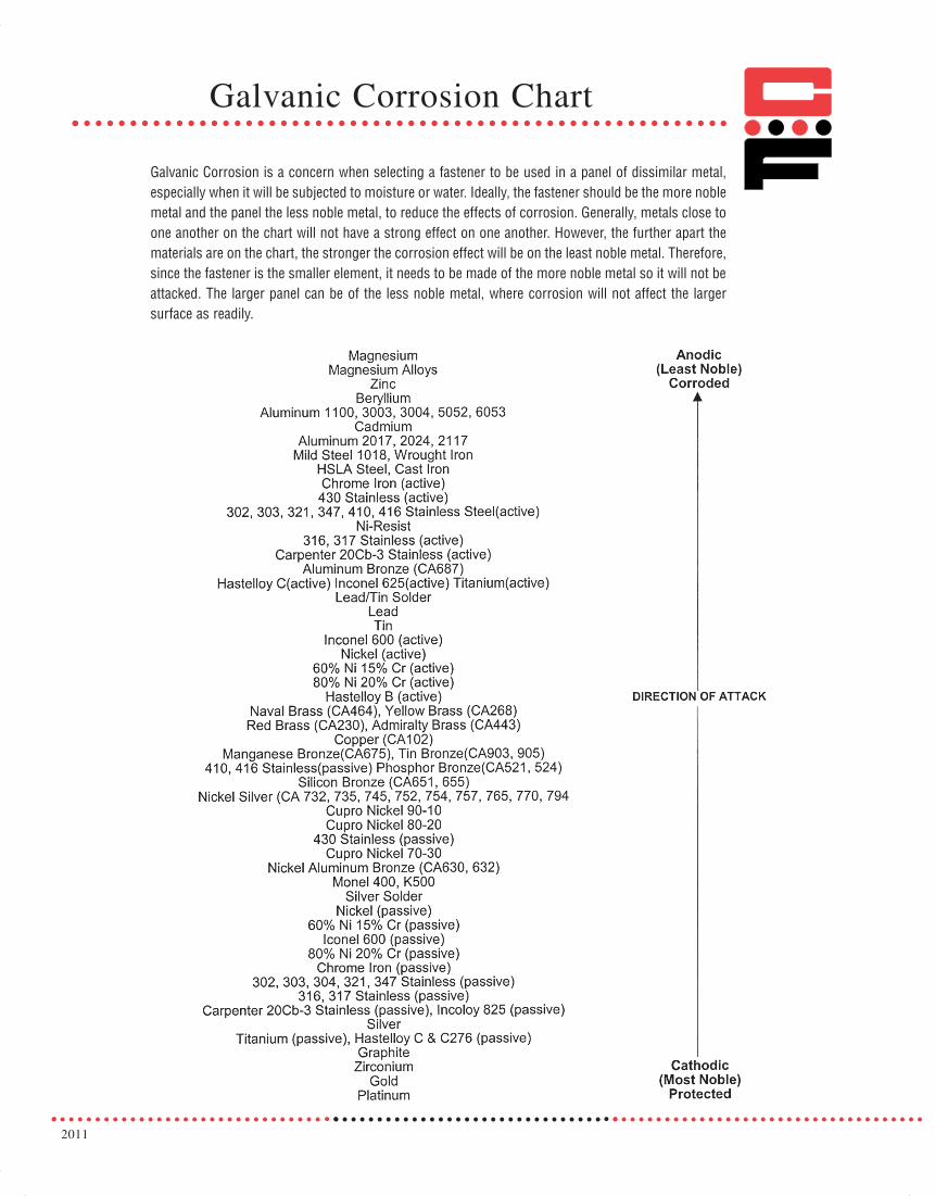
2011
Galvanic Corrosion Chart
Galvanic Corrosion is a concern when selecting a fastener to be used in a panel of dissimilar metal,especially when it will be subjected to moisture or water. Ideally, the fastener should be the more noblemetal and the panel the less noble metal, to reduce the effects of corrosion. Generally, metals close toone another on the chart will not have a strong effect on one another. However, the further apart thematerials are on the chart, the stronger the corrosion effect will be on the least noble metal. Therefore,since the fastener is the smaller element, it needs to be made of the more noble metal so it will not beattacked. The larger panel can be of the less noble metal, where corrosion will not affect the largersurface as readily.
071112 Captive_2011_Text_Catalog 12/5/12 8:22 AM Page 103

CAPTIVE FASTENER® SERIES PEM® SERIES PAGE
“PEM” is a registered trademark of PennEngineering®
CFAS, CFAC AS, ACCFFS, CFFC LAS, LACCFSP SPCFB, CFBS B, BSC / CS S,SS / CLS, CLSSCFH, CFHN H, HNCA CLACKN -CFL FCFE, CFEO FE, FEOCFEX, CFEOX FEX, FEOXCRT LKCPL, CPLC PL, PLCCH, CHS, CHA FH, FHS, FHAHCH, HCHS, HCHB HFH, HFHS, HFHBHCW HFETCH, TCHS TFH, TFHSCHE, CHES FHL, FHLSCHTS FH4CFA-1, CFA-2 / CFC-1, CFC-2 CHA, CFHA / CHC, CFHCCH, CHN, CHS, CHA FH, FHN, FHS, FHACGS TPS
CRM SMTSOCFKSSB KSSBCPFK PFKLPH-0, 1, 2 PF30, 31, 32CPFC2 PFC2CFSO, CFSOS, CFSOA SO, SOS, SOACFBSO, CFBSOS, CFBSOA BSO, BSOS, BSOACFSOSG, CFSOAG SOSG, SOAGCF40, CF40S DSO, DSOSCF4-S0, CF4-BS0 S04, BS04CFSKC SKCCFMS -CFSO, CFSOS, CFSOA SO, SOS, SOACFT, CFTS, CFTA TSO, TSOS, TSOACFSSA, CFSSS, CFSSC SSA, SSS, SSCCFHS-1, CFHS-2 CSS, CSOSCFWN, CFWNS WN, WNSCFS2, CFR2, CFN2 PS10, PR10, N10CPN, CPR PSL2, PTL2
Part Number Cross Reference Chart
CKF2, CKFS2 KF2, KFS2CKFE, CKFSE KFE, KFSECKFH KFHCKFB3 KFB3
9-1011-1213-1415-1617-2122232425-26
27-28
29-3031-3233-3536-3738-3940-4142-4445-4748-5051-5253
5960-616263-6465-66
67-73
7475-7677-7980-818283-8485-8788-8990-9293-9495-9899-100
54-55565758
071112 Captive_2011_Text_Catalog 12/5/12 8:22 AM Page 106

Conversion ChartInch & Metric
105
33716 Captive_2011_Cv_Cover 12/5/12 8:28 AM Page 3