08 - vibration effects and control in helicopters
DESCRIPTION
Vibration Effects and Control in HelicoptersTRANSCRIPT

§>‘\ \
L\R
t
g
oQ
Vibration Effects andControl in Helicopters
He Whareleura-tinKaihautu 0 Aotearoa
THE OPE NP0|.YTE(HN|(OF NEW ZEALAND
555—3—8
i

CONTENTS
Vibration
The Effects of VibrationPrinciples of VibrationSources of Vibration
Aerodynamic SourcesMechanical Sources
Methods of Reducing Vibration
Resonant MassNodal BeamCounterweights
Types of Vibration
Low-frequency VibrationMedium-frequency VibrationHigh-frequency Vibration
Measurement of Vibration
The Hand VibrographElectronic Vibration MeasurementThe Vibration Signature Analyser
Analysis of Vibration
Main and Tail Rotor Balancing
Main Rotor Tracking and Balancing
Main Rotor Blade TrackingMain Rotor Balancing
Tail Rotor Tracking and Balancing
Tail Rotor BalancingTail Rotor Blade Tracking
Drive Shafts and Cooling Fans
555/3/8
AIRCRAFT ENGINEERING
HELICQPTERS ASSIGNMENT
VIBRATION
g‘ In this assignment, we shall discuss the various kinds ofvibration that affect helicopters, together with their more
N» common causes and remedies.
A dictionary definition of vibration is
To shake, to tremble, to oscillate, to swing, tochange to and fro, especially rapidly, to resoundor ring, to tingle
Chambers Twentieth Century Dictionary
With the possible exception of "to resound or ring", thisdefinition fits the response of a helicopter to the variousvibrations that can develop in its rotating components.
Even a perfectly balanced shaft vibrates at all rev/min,but at certain well—defined rev/min ~— for that particular shaft
i —~ the vibration becomes severe. This is a material effect thatcannot be avoided, but it can be minimised by avoiding those
= critical rev/min or by accelerating and decelerating throughthese rev/min without any delay. Most of the vibrationsexperienced in a helicopter are not natural ones but are theresult of a rotating component or components becoming unbalancedThe severity of the vibration will depend upon the amount of"out~of~balance" and the speed of rotation of the component.
5/8“/~15 ssa/3/s
8
_ 2 _
The Effects of Vibration
To the flight crew and passengers, the vibration of ahelicopter can cause physical and mental effects, ranging fromslight worry and annoyance to definite pain and distress. Tothe pilot, these effects can lead to an impaired ability causing,say, a poorly made landing at the end of a flight. To the 'passengers, these effects may cause such a deep distrust of thehelicopter that they will refuse to fly in one again.
Of equal, or greater, importance are the effects of allvibrations to the helicopter. These effects include
1. Accelerated wear
(a) In the bearings, control rod ends, cables,pulleys and fairleads, and bellcrankattachments of flight control systems;
(b) In the bearings of all rotating parts;and
(c) In all instruments.
2. The cracking of fuselage skins, frames, andstringers (especially near the tail rotor).
3. The loosening of rivets and of the attachmentsfor component parts, which in turn leads tofretting and to corrosion.
H. Internal damage to electronic equipment.
5. The reduction in "life" of lifed components.
The "life" reduction of lifed components, which is especiallydangerous, is brought about by the forces that cause thevibration changing the point of failure of the component on itsS/N curve.
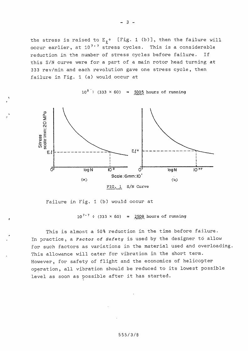
Figure 1 (a) shows a stress cycle fatigue curve ~— S/N curve—— that does Q93 represent any particular component or material.On this curve, Eg is the endurance limit for failure after 108stress cycles. If, because of the forces causing the vibration,
S55/3/8
_ 3 l
the stress is raised to Eg+ [Fig. 1 (b)], then the failure willoccur earlier, at 207'? stress cycles. This is a considerablereduction in the number of stress cycles before failure. Ifthis S/N curve were for a part of a main rotor head turning at333 rev/min and each revolution gave one stress cycle, thenfailure in Fig. 1 (a) would occur at
108'? (333 X 60) = gggé hours of running
ZOMPG
FTHTI
Stress scoetm 81-
_____________ ___ 55+ --_---~-----__
or--Q QJ 6%-—- 1|it6' io9N logNSc0m:6nvnflO' »
(e> (s)FIG. 1 S/N Curve
Failure in Fig. 3 (b) would occur at
107'? % (333 X 60) = £§Q§:hours of running
This is almost a 50% reduction in the time before failure.In practice5 a Factor of safety is used by the designer to allowfor such factors as variations in the material used and overloadingThis allowance will cater for vibration in the short term.However, for safety of flight and the economics of helicopteroperation, all vibration should be reduced to its lowest possiblelevel as soon as Possible after it has started.
555/3/8

_ u _
Principles of Vibration
The speed at which vibration takes place is known as freguencgand is expressed in hertz (Hz). One hertz is a frequency of1 cycle per second, where a cycle consists of movement in onedirection followed by movement in the opposite direction andthen a return to the starting point.
The amplitude (range of movement) of the displacement thattakes place during vibration is usually measured from the meanor equilibrium position, but it may be measured on a peak-to-peak basis. The units used for this measurement are inches,mils (1 mil =' 0.001 inch), or millimetres. Because it isdifficult to measure amplitude directly, the related functionof velocity expressed in inches per second or millimetres persecond (in/s or IPS and mm/s) is often used. Because thevelocity is not constant, the figure used is the velocity ofthe point being measured as it passes through the mid-positionof its oscillatory motion. Figure 2 (a) shows the termscycle and amplitude as they are used for vibration.
, 1 Cycle\
\
Dspacement
ll. — W ~ e t W ,;"‘: Time
_____ ____ __ Amplitude
\ (A) DAMPED VIBRATION
~~:W \u[>mm
(B) mvsneem" v|an/mom
Dspacéinent
FIG. 2 .Forms of vibration
555/3/8

Y Hz
_ 5 _
The velocity of vibration may be related to actual displacementat a given frequency by using the formula
D = _!l
where D is the displacement amplitude in inches omillimetres (i),
V is the velocity in inches per second or
Zwf
millimetres per second,
f is the circular frequency (Hz), andTEVmin
Example: What is the displacement (D) of a tail rotor witha vibration velocity (V) of H IPS at 3000 rev/min” (This 1S asevere imbalance)
D2
The displacement is 0.013" each side of the mean or apeak-to-peak movement of 0.026" (2 X 0.01
Example: What is the displacement (D) of a main rotorwith a vibration velocity (V) of 38 mm/s at 315 rev/min°
D:
is the *T- X 60 (cycles/second)
“X.Zflf
iL_2w5O
0.0127
Qlgéiaa
_Y_Zflf
__%i__mH5.2&
iakififi
555/3/8

_ 5 _
The displacement is 1.15 mm each side of the mean or a peakto peak movement of 2.30 mm (2 X 1.15 mm).
Another term met when dealing with vibration is resonance.Any object that is flexibly mounted has a natural vibrationfrequency. This is the frequency at which it will naturally vibratewhen stimulated by an outside source. For example, if a thin _wooden ruler overhanging a desk is struck at its end, it Willvibrate at a frequency that depends on how much of the ruleroverhangs the desk. If a small weight is now fixed to the endof the ruler, the natural frequency will be lowered; the forceused to strike the ruler will not alter the frequency of vibration,but it will alter the amplitude; and the vibration of the rulerdecays as the stimulation is removed [Fig. 2 (a)1. However,should the stimulation continue in phase (in time) with thenatural vibration, the amplitude of the vibrations will increaseEfig. 2 (b)] to the point where the strength of the ruler isexceeded and it breaks. Ground resonance is an example of thisform of vibration, as we shall discuss later in this assignment.
Rotor
-<—i— Spring (A)
t <w--—-VVmght(B)
(a)Rotor
'-s-——-—-—-—-—-- Spring (A)
L -e---—— Weight (B)
as-Spring (0)
+ 4--i—*—--Weight (C)
(b)FIG.&§ Dynamic response to vibration
(:1 (rs (J1
Figure 3 shows the dynamicbehaviour of a helicopter ~structure in greatly simplifiedform. in Fig. 8 (a), a springA and weight B form a systemsuspended from a rotor thatexcites the system. The mainexcitation frequency (Hz) willbe given by the number of rotorblades multiplied by the rev/secof the rotor. Weight B respondsto this excitation in a way thatdepends on the value of theweight and the natural resonantfrequency of the weight/springsystem. This response couldbe naturally damped (attenuated)or it could be divergent(amplified). If a weight C is
/3/8

_ 7 _
hung on weight B by another spring D [see Fig. 2 (b)], then theoriginal response to vibration by weight B will be modified.Weight C will respond in opposition to the exciting force fromweight 8 and tend to reduce it - or cancel it if the naturalfrequencies of the two weight/spring systems match each other.The structural response will now be zero. That is, the vibrationhas been absorbed.
In practice, the absorption of vibration in a helicopter isa very complex matter. Because the structure is not a singlemass of uniform material, because the rotor speed varies, andbecause the main rotor is only one of several sources of vibration,it is not possible to eliminate all vibration from a helicopter.However, careful maintenance with special attention to rotatingcomponents and accurate rigging and balancing will keep a helicopterto its design standard, and vibration levels will then beacceptable.
Sources of Vibration
The two sources of vibration are
1. Aerodynamic, and
2. Mechanical.
Aerodynamic Sources
The primary sources of aerodynamic vibrations are the mainand tail rotor blades. Bach blade is of airfoil section andprovides lift, or thrust, or both, and aerodynamic disturbanceswill cause vibrations of a frequency depending on the speed ofrotation and the number of blades in the rotor. For example,a two—bladed semi—rigid (teetering) rotor will have a normalvibration of 2/rev, and a five—bladed rotor will have a normalvibration of 5/rev. (These normal vibrations pass almostunnoticed because of good design.) However, differences relatingto one blade only, such as minor damage or natural ageing, will
555/3/8

- 3 _
cause the blade to develop more or less lift and drag and thusproduce an additional 1/rev vibration. In an articulated rotorvariations in blade spacing (blade phase) will cause similarvibrations, and if only one blade is affected, the additionalvibration will be a 1/rev. A variation of track of one blade,on any rotor, will also produce an additional 1/rev vibration.if two blades are out of track, there will be an additional -2/rev vibration. The same is true of a tail rotor, except thatthe vibration frequency will be higher because of the higherrotational speed of the tail rotor.
Under some conditions, a disturbed airflow can cause thevibration of elevators, stabilisers, cowlings, and access doors,but more often these will vibrate in sympathy with some othersource if their attachments are loose or worn.
Mechanical Sources
Mechanical sources of vibration are, simply, rotating partsThey are conveniently divided into transmission sources andpowerplant sources.
Transmi§siQn sources: ‘Sources in this group can be listedELSZ
1. -Rotors: A rotor will vibrate as a result ofany out-of—balance condition or because ofwear in its control linkage.
2. Drive shafts: These shafts may have to be balancedand=specially assembled on to the shaft couplingsto keep the balance of the.whole assembly.Misalignment of a shaft can cause vibration asa result of the slight flexing motion produced.Wear in support bearings and coupling splinesare further sources of vibration.
3. Gearboxes:These devices have components runningat.different speeds and supported on differentkinds of bearings that provide sources of vibrationat several frequencies. Also, due to theaccumulation of manufacturing and assemblytolerances, gear teeth may vary slightly inposition, shape, and mesh at different positions
555/3L8
7

_ 9 _
on the gear, which results in vibration. Varyingloadings due to changes in helicopter attitude andairspeed are transmitted through the rotor mast,its support and thrust bearings, and the drivegear train bearings to give changes in vibration.ln addition, many main gearboxes provide drivesfor such accessories as generators, hydraulicpumps, and tachometers, and each of the componentshas its own characteristic vibration, which mayvary with differing operating conditions.
4. Ancillary equipment: Cooler fan_units that supplycooling air for the main gearbox oil cooler and,sometimes, for the engine oil cooler may be driventhrough a belt drive by the tail rotor drive shaft.This unit may vibrate due to defective bearings,damaged fan blades, or defective drive belts. Arotor brake device may act on the tail rotor driveshaft and can give rise to vibrations if itsbrake disc or pucks are damaged.
Powerplant sources: Powerplants fall naturally into the twodivisions of piston engine and turbine engine, each having totallydifferent vibration characteristics.
1. Piston engine: The piston engine, with its onepower stroke per cylinder for every two revolutionsof the crankshaft, is a prime source of vibration,the severity of which depends on the number ofcylinders ~— the greater the number of cylinders,the smoother the running of the engine. Thevibration is transmitted not only through theengine mounts but also as a torsional vibrationthrough the crankshaft into the helicoptertransmission. For this reason, many piston-enginedinstallations use a flexible coupling between thecrankshaft and the transmission, and the_crankshaftitself usually embodies counterweights to absorbtorsional vibration. This last reason is why onlythe speeified engine model may be fitted to ahelicopter, as seemingly similar engines may bevery different in their vibration characteristics.
2. Turbine engine: Although the turbine engine isnaturally smooth running, its higher rotationalspeeds mean that the effects of any imbalance aremagnified as much as ten times compared with apiston engine. Ingestion damage to compressorblades, creep damage to turbine blades, and wearon bearings and seals are all causes of abnormalvibration. As with the helicopter main gearbox,all engine—driven accessories can produce noticeablecharacteristic vibrations, which, on the pistonengine, are hidden by its usual clatter.
555/3/8

_ 19 _
Methods of Reducing Vibration
If good maintenance practices and attention to detail arefollowed during all maintenance and repair of a helicopter, thenvibrations will be kept.to an acceptable level and the helicopterwill fly safely and well. .However, there will always be acertain degree of vibration natural to the design of a helicopterWe shall discuss below some of the ways that manufacturers dampenthese natural vibrations.
Resonant Mass
The principle behind this vibration damping method is shownin Fig. 3 and explained on page 6. One type of helicopteruses its 2H d.c. battery and mount assembly supported by threecantilever springs, as the resonant mass. [This is weight cin Pig. 3 (b).] The spring length, which is adjustable, is setduring construction using special equipment. The assembly istuned to allow for any variation in battery weight by adding orsubtracting weights, weight being added to lower the resonantfrequency.
Another application of this principle is used in the cycliccontrols of a helicopter to prevent vibration being transmittedthrough the control runs. See Fig. M.
555/3/8
:1/.1';;¢;';.e¢&>:.~» we " ;”' W " .'.. ’ ’ "'§s§€;;¢ .. /.». .-22¢
_ 11 _
»~=.:=~,'@<e'i.QQ”?/'§/aft“ .'Z~ 5 =€e
>;#..~.~,e/1/fiwe‘ .9*. -’/%/6* ~ FTé_—I-1,_____ ,1 5'5 .4._-=; ~',;.'1/e u . ..,~;@’/:¢§%%%%%%e€ewes@~re
’ W "~ /4‘ /. </\ /3»-Mi
/ C‘
1:2;-g
E.. ’§¢§.l:""F‘=>= Q“">'5*=j:‘.a
1 -*5"-"'?" .?§.;/i.:2§r;§1::-;_::;=.:-"”4~./s~./’“.‘w 3 ~ §“"?'f:'>:'.7.:~E“'9~,-
%a%%aa@%g@%eea:<. e. .....~... .. .. ... - ;—~.¢;T..3:_........¢.M».»+,sw:~s.=e-» M 1. -
<-‘;§.»=¢ V. £'~'; 1" 4';2:»-51-r<'=;<§:.-==-:-'2 He-¢\.~./..w».\¢%’;~./~ . '4/;/.. .' >..~.\»-~.~./-.,. __. ._ _ . . ..,,...,.~.. /,,_»\\§\_,_),,.,-= r.‘:>T:I:'1=Ii;-*'<..i»I;;‘->2;-='::assess “”% "a /“.2 \”;;I§“%/~8 Y“__ " 9., re)», XN »
e-..~..- ». =5. V . .
'\‘,\;'E§§
W» . < aasaasr \-I§=.:‘-‘*?'."'1i'lI:;;;’:@ %e*wsww
...‘-.~'='='.'‘ 55--'s;»i5;§=:‘_:.=;._.~'-*-==-3 it-‘-'q="fl..,':,=5.="‘i5g§_;.'I{,;.; 1;::<:~_~_;_._;:.‘-‘_.\:\.a-‘j;_. I:;',1;"'-'="*‘:':‘.‘i"I
"EM*2,’‘*<"llM....€:_9:w,w».'!‘. .w_w-w '1‘-4-:i;Z=‘ .‘-=-,‘;:I1>’<;>=./":2-/,'.~:~;I=:~¢-W ..-TI1-"PI
‘fig.;.
<.".»,_‘
, .-:-,\>.~<‘Y1:
g5/i‘:'
>\-<=v
>’Z§§>s’) ,‘
.. _':;;.;-,:4 1;--1
<=.~,.»_<.. >.. ..--..--.~.. .~ .55.; '»-‘e:»=:;e~:-~‘&“ . ~,.»:/~>:; =.;.;-1-,»,;;.~ ,,. 1-av-11:’
, ‘ at gs Q1’&‘:.--»
’ » ,. cw, . ‘--1»-......
‘ 1312/~' ‘=\.;<;;.-:='(a-I -",, / . .,
1;:-1 :.'.¢'~"/»</_<-1<';»~.<.\.,,¢~-'~. =- ..1
~,-_~":-.~ '»;a~~.- ass’ . . .-.,— e-2 er"1" ==':fi2;‘<=;'
'11‘; ._.,..~>,--.,--.; -. .- »; as _ , . -r::'»‘>-="»
saaassaasa§aaeee.;%@_-.s-.sattat*»ilaeastasaaasa%saeeeee*’+~,‘_:= ' ' '='$»,/>-A1 \.-/,>»»¢<. ~-1» ;*-'*:.§'::/I-.-;::.\;
I x isaaegereai
,/ V » 3_e,g.~~. -=4’ \~,;.W ,¢¢ ;<3§WV~/,“" WW,’ ~ * > ~>
1*-“ \ x Q v» 3 »"~,.,-¢-=m.a~*1=\-;\.:;..;». @.<>4,~»=<;:¢>>:¢:4¢e<@%3Z%s¢$za4__._-.,...,...v.= .~.. -.. .._.»,,.\.-,. ..».»».,»,,».;»,,;;... ax .»\,»»*/N‘;-\,’ q
.‘'_i;.::§'.‘:‘»':*' ,» 2*‘ ". ’;4"'A'>.-.§3.-“.-’5:‘\’Q‘>.<€“:I»14m~~~~asaaaMis
W.» a * * ‘
. _. .-.4 ,1, . . . {.3 ~_ : _. "\~);.,_ ; ;';_ ,__,. ‘ - : 4' ';- '/.I»Z\ ,_, 1:;- a -7,-\~: .-_ ‘ =' pa ~4~..~»c->-»\ __ ,. _.wt .\ \- \: ':<-2¢:;£t>m;"*- W-’ E at »- . Wis?1‘ ._, @»:=,1.~ ‘__. _ :._ ,,:.,_.\.,.g,,g;;,
rs 1-~1e§;s:§§%§sease:-_ = Z>:--"-».:1.~,.., .. ,..., , .' e= .4‘-'.-5' '¢31§55Z>;' IW- .;£h V
~~'-s==.§ - -'>»»<-i¢;/a4<;.~:;,=<;,_*.> :. 7:1" \
»:.>w~§%’ Q” .4‘:...-,'<;=.ese;=. -.;._._ 7-5*?-I_, ~' as -'1-I ii“ "1>»<-W :1,-97.~‘ ‘
~/A- ..» .%%%E§fi%'
an 1 A N ‘ ' my_ _ _.__ . . — , 7 - -s A'\*: _ ~-7 . ...: _-11 I -.:= -'—"- /- ' '- A 41.1 ‘.~‘.-é.-5-ac \,7;.,.=..-..~, W: #-
11-"I-’ - -1- -:' _' "1 *f§=% ex; -.';. L ' at ~ .-' -_ '- '1 =" ' .€"- . /’ sew‘, ‘i. :'i_. .>'. -'_1‘— J1 .' »; .' .1 "3"? Q; ;=.--'/A-’i1,>; -' ~ I .'.<\'j=.-~'>f,’5:?.~.e‘-s;=,a>£7'-/:j?~;'“
....,'<-';: ‘Ti-Ifi2';€=r -=-_-,_;,.;:<-, ;..._ -\.;_,;_.:: _¢, .1 .~u¢v~,;‘“* ' : __;. as a? t;eaeeaiase'
..»...___ I -::-_—-:'= re --_.-a. '=-‘ 5/£1 ."<'-1&1."-=’;;\’..-§»'*.i;:§i,>:-»-;_:=-:==" .~'-I‘/1:?-It~.'»-'-. ..-as ' _L .1 L ».,.,-».aea~ .:=- .,. WE: ; .. ..,v@.,.,..-.-,_.......»..»....,=ae»>.»~»
=\ sea-;<1~‘>*'--"\ _.,, . ssesegggseeaassggeesgtaasa2aseeeeeaeseesagaea;-t:“< = --,_;.=_;:=;=.;see';>21; ..5 ., £1-5;5%.»; .,.,__.» ...>.s.,g_.,_. . 9. .. 1, . :/—_1§_ .» . . v- .\..~#~.»»f.2» 1,;’ < r“I ':i~e.:;.".;<.-.~=\;-._ :5;4' r" 1"’ ', ~’>"~-‘W:-./'~'‘('1' i *\"—'~ (,1->,,,/¢~.~>»‘~=1=a>¢§::s5:i. ~ ..-=';1:.:%_ "'\.':':'; .--I-.1~;:..-;;-1 : 1;$—.» a
% £!i=;=-"L ‘I-‘1'E>‘;\,:».1:-.-.. . 111%; ‘£1. .—;_;=;=?5—; 1 ‘.-.-‘.. ism:31. »' -. p@n' .:::I}}~;;2~ E-::'=-5-::_ ‘>:-5;: ' '51,3? .: :3§.¢;;., Ev~ "W '»~ :— V ‘— \v1~?1’:<:»~>==:w@:~&¢»%~ 14¢;'1"?'<1;§‘":=1~‘E=I-1:1» -» ea? age '» 1:»... . ..‘=22; sé;-*2‘.
,~.,_ff, I3.._§.I;=;. ‘ 7' ' ' ;— j135:5, '.N‘.
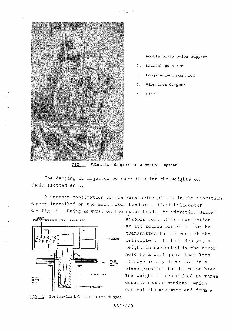
FIG. 4 Vibration dampers in a control system
l. Wobble plate pylon support
2. Lateral push rod
3. Longitudinal push rod
4. Vibration dampers
5. Link
The damping is adjusted by repositioning the weights ontheir slotted arms.
A further application of the same principle is in the vibrationdamper installed on the main rotor head of a light helicopter.See Fig. 5. Being mounted on the rotor head, the vibration damper
SPFHNG{ONE OF THREE EQUALLY SPAGED AROUND A505)g|_
F1MiM17
i
|MAI Nsownwxsr
Id-LL’ U
_1§1s. 5
WEIGHT"QMAINROTORHEAD
SUPPORT TUBE
BALL JOINT
Spring~loaded main rotor damper
absorbs most of the excitationat its source before it can betransmitted to the rest of thehelicopter. In this design, aweight is supported in the rotorhead by a ball-joint that letsit move in any direction in aplane parallel to the rotor head.The weight is restrained by threeequally spaced springs, whichcontrol its movement and form a
585/3/8

_ 12 _
tuned system. This system is excited by the vibratory loadsdeveloped in the rotor head and responds in opposition, thusreducing these vibratory loads. -
Nodal Beam
The principle of a nodal beam can be demonstrated witha long, thin piece of wood. If you hold the wood at its mid-point and shake it up and down, the ends, because of theflexibility of the wood, will move in opposite directions tothe mid-point. That is, they will be out of phase. This willoccur when the induced vibration is near the natural vibrationfrequency of the piece of wood. The positions on the woodwhere the motion changes from one direction to another areknown as nodal Qoints. Here, there is no movement. If a beamarrangement is built up, see Fig. 6, and a helicopter fuselageis attached at these points, with the gearbox and rotor attachedto the centre of the beam, then the fuselage will not besubjected to the vertical vibration induced by the rotor.
vnamvrme component . 'moron AND ssaneoxl _
/~ FLEXIBLE /X/ ‘ Q,__ ‘I I MEMBER A ,\\ __\ f ,’'~J\ ""
‘ Is‘ ,c a-. ,/\,_ , _,
“'~ , 4". ~,_‘ _,- ‘
F_ _ _ _ __'
‘ NODAL. POINT
ATTACHMENTINSRTIAWEIGHT
//////.4./..( T ///////// _FIG. 6 Principle of nodal beam damping
In a helicopter, the beam consists of flexible members withinertia weights attached at their ends. These flexible membersmay be formed from glass fibre with a low Young‘s modulus ofelasticity (it is quite an elastic material) and high allowablestress that is fairly easy to form into complicated shapes.
555/3/8

M 13 _
The mounting to the airframe is through elastomeric bearings,and the response of the system is adjusted by tuning weights mountedOI1 arms
Elastomer: A rubber—like substance
Figure V shows an inservice version of a nodal beam dampingassembly. Compare this system with the one in Fig. 6.
a-ww*\m
!\
" _ >‘ _ _¢;r 3’ ,
i’LQ£fi§$§§L/
» zii» ,~\~,
L/ 7.,i%_.~;._€-‘
E"73; ,1 _,Av»
~‘§Z?_»>-,-
P?
\
G
\F*»_ 1 £E§§%§g!!!
W * ’ Q‘S i .6:-‘//t \I\‘~fl\ i
/i%§" ‘e5§§§§§%5’ 'aau§ \ aQz:iEt\\ ‘\$' , 1' " . . ‘ ‘"1 '7 _ \"‘ ‘G
, " ; i Q ‘Q "~11‘*
links
.L§;Gig
A
i?‘%*H 3 .__‘ \ t ‘~ Q1 \\ 31- 3 '
1. Transmission to nodal system 3. Glass fibre flexures
2. Tuning weights
¢a,q§sEJ;“ "Q& . J. )6 4/- V ‘V w_i_.¢-- >
%¥?#%A i“’ i&§wmfi%§§§§;%mlH-4%
1____....——figs.’
fin
,“H "/0 ‘Q\ E:If /,
\l@ir vb§»;‘=\4/?’ '3;
4. Fuselage mounting points
FIG. 7 A nodal beam damping assembly
Counterweights
One type of vibration damper that does not have springs, usedin at least one model of helicopter, is generally known as apendulum dynamic vibra ion damper A vibration absorber assemblyt .
is attached to each main rotor blade so as to rotate in the same
555/3/8

....j_l.§._
plane as the rotor. It consists of a support bracket that carriestwo pendulums loosely mounted and free to move within therestriction imposed by the support bracket. Figure 8 shows avibration absorber installation. ~5t5'“BRACKEI
,,_ ¢>‘ * y///F \\\\ ‘I’ , .} U
,/“ |~ /' -i‘
§_* % “L-A 1s /i y‘iii ‘ 5 P. - ER REVOLUTION
PENDUKUM
l\\e"9e~\ 17'‘—m\éll“\t 3'PER REVOLUTION, /PENDULUM
FIG._§_ Vibration absorber
This vibration damper uses the inertia forces generated bythe in~p1ane pendular dynamic weights to oppose the forcesgenerated by the rotor. Because the weights are subject tocentrifugal force, which varies with rotor speed, the dampingprovided by this type of absorber is effective throughout theoperating speed range.
Types of Vibration
Vibrations in<1he1iccpter can, for practical reasons, beconveniently put into three ranges:
1. LOW frequency —— 'i TO 7 h(~‘(*1j7,,
2. Medium frequency —w 16 to 30 hurts, and
3. High frequency —— 30 hart; and upward.
S55/3/8

_ 15 _
This classification is rough and ready, but its use is ahelp when diagnosing the cause and source of a vibration.
Low-frequency Vibrations
Abnormal vibrations in this category are nearly alwaysassociated with the main rotor. The vibration will be of somefrequency related to the rev/min and the number of blades ofthe main rotor. It is very often referred to as a "1 per rev","2 per rev", and so on. A "1 per rev" is usually slow enoughto be counted without any help,but a "2 per rev" can be impossibleto count without resorting to a vibration measuring instrument.For example, a helicopter with a rotor speed of M20 rev/min anda "2 per rev" vibration will have a vibration frequency ofis hertz. You calculate the frequency by finding the productof the rev/sec and the vibration per rev. Thus:
420 (rem) X Z_(vibrations), = 14 (vibrations)60 (second) 1 (féfil 1 (second)
= _.L.%..5s
A 1s—hertz vibration is too fast to count unaided.
The frequency and strength of a low frequency vibrationwill cause the pilot and passengers to be noticeably bounced orshaken laterally or vertically or in a combination of bothmovements. '
A vertical vibration is usually caused by a main rotor blade(s)being out of track, and a lateral vibration by an out~of-balancecondition of some kind in the main rotor head and blades assembly.These vibrations may change in strength with rotor rev/min, withairspeed, and with power-on and power~off flight. Specificinstructions for these vibrations will be found in the maintenancemanual for the helicopter. However, in using these instructions,you must be prepared to find and rectify a cause that they maynot mention.
555/3/8

-16-‘
Ground resonance: This is a form of low-frequency vibrationfound only in a helicopter on the ground that has
1. An articulated main rotor head (whose bladesare controlled in their movement about verticalhinges by lead-lag blade dampers), and0
2. An undercarriage system with a sprung undercarriage.
If either of these two conditions are removed, then groundresonance cannot occur. For example, neither a helicopter withan articulated main rotor head, mounted on floats or skids, nora helicopter with a semi~rigid main rotor head, mounted on asprung undercarriage can get ground resonance.
The vibration is started when one or more blades move ontheir vertical hinges to become unevenly spaced in the rotor disc.
See Fig. 9. This unevenspacing means that the centre of
Ollploced bladegravity of the assembly doesnot coincide with the centre ofrotation of the head. Thehead then tries to rotate aboutOlaplncod \
C M G ‘ Contra of mum ‘¢ the centre of gravity and,
1’ ‘~ as a result, the fuselage rocks,a low—frequency vibration,from side to side.
§E§L_g Displaced blade
when the period of the fuselage vibration coincides with thenatural vibration frequency of the undercarriage, the rotor-induced vibration amplifies the undercarriage vibration and viceversa. The result is a very quickly growing vibration amplitude,that, if unchecked, will cause the helicopter to roll far enoughfor the blades to touch the ground. The helicopter usually endsup on its side on the ground, destroyed. Figure 10 shows,simplified, the development of ground resonance.
555/3/8

_ 17 _
Ground resonance can occur
~7L\ 1. As you are bringing themain rotor up to operatingrev/min from a standstill;
a--~_¢$' 2. During taxying over rough
or uneven ground;
“ 3. If the undercarriage oleoI5 ‘ y struts and tyres are
:ii_ - o rial __ U- _ incorrectly inflated; or
H. If, during landing, thecyclic control is moved
\ suddenly as a main wheeltouches the ground.
,/,¢¢¢aI§r¢,',,,, The'immediate cure for- “ ground resonance is to lift
ifthe helicopter off the ground,
1
pi @_ T whereupon the rocking motionswiftly dies down. if liftoffis not possible, then therotor must be slowed down and
. stopped as quickly as possible.§%5x:x\ Use the rotor brake, if one is
vg» fitted, to do this.
<Jqék‘fiiip §§5$
FIG. 10 Ground resonance
The rocking movement of the helicopter in ground resonanceis violent and develops very rapidly. The pilot must be securedby lap straps and a shoulder harness in his seat so that he canregain control of the helicopter before it destroys itself.
555/3/8

....j_8...
NOTE
Because of possible ground resonance, it isusual for a helicopter with an articulatedmain rotor head to be ground run only by aqualified pilot.
Medium~frequency Vibration
These vibrations are too fast to be counted unless aninstrument is used. In some helicopters, their source will bethe tail rotor and its associated drive—shaft.
High-frequency Vibration
These vibrations are too fast to be counted unless aninstrument is used. Their usual source will be the engine, buton some helicopters in which the tail rotor rev/min is nearlyequal to or greater than that of the engine rev/min, thesource could be the tail rotor. In this case, a means ofpositively identifying the source will have to be devised.
SUMMARY
Vibration causes accelerated wear of components,cracking of skins, and frames, loosening of rivets,and internal damage to electronic equipment. It
\ also reduces the "life" of lifed components.
Careful preventative maintenance will keep vibrationlevels to an acceptable standard.
Sources of vibration are either aerodynamic ormechanical.
\\
The sources of aerodynamic vibration are the mainrotor blades and the tail rotor blades. T
Mechanical vibration is caused by any rotating partthat is in an out—of—balance condition.
555/3/8

_ 19 _
Three design methods used to reduce natural vibrationsare
1. Resonant mass,
2. Nodal beam, and
3. Counterweights.
Vibration frequency is measured in hertz (Hz).
Vibration amplitude can be given in inches, mils, ormillimetres, but it is usually given as a velocity ininches per second (IPS) or millimetres per second (mm/sec)
PRACT
' 2.
ICE EXERCISE A
In each of the following, choose the option that correctlycompletes the statement, writing A, B, C, or D as youranswer.
1. The natural vibration from a three~bladed mainrotor would be a low frequency:
A. 1 per rev
B. 3 per rev
C. 4 per rev
D D. 6 per rev
The probable cause of a low frequency 1 per revvertical vibration is
A. A main rotor blade out of balance
B. A tail rotor blade out of track
C. Nothing unusual
D. A main rotor blade out of track
3. A tail rotor turning at 3000 rev/min has one bladeout of track (to give an impossible to count1 per rev vibration). This vibration will have afrequency of
555/3/8

_ 29 _
A. 3000 Hz
B. 60 Hz
C. 50 Hz
D. 30 Hz T
4. The peak-to~peak displacement of a main rotor turningat 420 rev/min with a vibration velocity of 6 IPS is:
A. 136.4 mils
B. 68.2 mils
C. 273 mils
D‘. 546 mils
NOTE: 6 IPS gives an unacceptable level of"“*“* vibration.
(Answers on page 50)
Measurement of Vibration
An assessment of the level of vibration is often all that isneeded to know that something is wrong, or going wrong, with ahelicopter. However, knowing that a level of vibration isunacceptable does not tell you its cause. Some faults haveobvious and well defined symptoms, but many can be hard to locateand careful and systematic thought and actions are necessary toidentify them. To do this efficiently, you must measure thefrequency and velocity of the vibration. Three instruments thatmay be used to measure vibration are:
1. The hand vibrograph,
2. The electronic vibration measurer, and
3, The vibration signature analyser.
555/3/8

_.2j_...
The Hand Vibrograph
This instrument consists of a steel reed with a weight atone end. Varying the length of the reed will vary its naturalvibration frequency, the length being calibrated in hertz.
To pick up the maximum amplitude, vibration measurementsshould be made in the flight conditions where the vibration ismost noticeable —— but only if it is safe to do so - with thehand vibrograph placed against the aircraft structure as closeas possible to the suspected source of vibration. Remember thatvibration may be found in both vertical and lateral places, andso readings should be taken in both positions. From the vibrationfrequency given by the instrument, the source of the vibrationcan, with some detective work, be found. A different form of thisinstrument gives a readout in the form of a graph. Figure 11shows a trace, with diagnostic additions, from a hand-heldvibrograph.i um time
1<——1 Rev of rnoin rotor —-|
+ ..3 “ '‘Y 1i“\ I‘ !"‘\\>'urJ’ \»‘~\»J'J“\\ 0‘ l!m\) 1"! \\*'-1,4It. t . t ' . , r ’‘ \l‘\“p{ \),;\vJ *!\\J' Q,‘-‘An
I 4~ -+in .a»- _ .1» _~
Y%sQl§§%Efi$ag§gw _., ‘Qwfi‘§%¥flAaE$g .iy!@\\“'
sex J" vi’ 2g§i~be t>21..I"=:(_in."FIG. ll Vibrograph trace
555/3/8

_ 22 ,
Electronic Vibration Measurement
In this system, an accelerometer is mounted in the helicopterin either a lateral or vertical position, and its signals arefed to an instrument that electronically processes them and thendisplays them on a meter. Some forms of this system use twoaccelerometers, both reading at the same time, and whose signalscan be selected as needed. Besides the accelerometer(s) a 'magnetic pickup is fitted to the main rotor to provide a phasereference of 1 signal per revolution of the rotor. This signalis fed.into a display that shows the phase relationship betweenthe rotor and the vibratory motion and is used to determine thelocation of any balance weights that may be needed. In thecase of the main rotor, this display ~— the clock angle We is.__._-_.--____..................._.....
in the form of a circle of 2% lights giving such positions as"ten o'clock", "half past two", and so on. For a tail rotor,the clock angle is shown by a reflective target or by specialpaint fixed to a blade that is lit up by a strobe light slavedto flash in time with the vibration-
Many helicopters have magnetic switch actuators permanentlyfitted to each push—pull rod attachment on the rotating star.All that needs to be added to make a vibration check is themagnetiC piCkuR from the instrument kit. This pickup isinstalled, as a temporary fitment, on the fixed star. See Pig. 12
555/3/8

-23..
.fail/
ééi-we @1575II9E/'0Q\\! “a
pp\\\lr“"-—-*"“““"\ Y
N03
»ill‘; VI
%;O |'\J
mnkn eat?‘as‘ t ”’@e$%@%T@_ sum %%: MAGNHWC _ ..;io.n2sm. ..em» PICKUP if A
CABLE \ II » TA PE
FIG. 12 Magnetic switch indicators and magnetic pickup installation
when carrying out a fault diagnosis of a main rotor, firstcheck the blade track and, if necessary, correct it before youdo any rotor balancing. Blade tracking involves
1. The adjustment of individual blade angles toensure that all blades "fly" in the sameplane, and
2. Where applicable, rectification to ensure thatall the blades "fly" equally spaced within therotor disc.
Blade tracking is discussed later on.
For main rotor balancing, install the accelerometer(s)and magnetic pickup in their correct positions in the helicopterand head the helicopter into the wind on flat, level, firmground. Avoid operation in gusty conditions or in windspeedsabove 15 knots as these conditions may mask faults. Run therotor on the ground at its nominal speed and rough—tune the
555/3/8
E; .M;‘Jd _ I”no.1 _xggsazncwy _/ no.1
Qfiii sown? <L_ ‘ ¥;:>i_____ ADJUSTMENT .
Y i NUT !--—-~I 3 r"

6
_ gu _
electronic equipment to a frequency corresponding to a 1/revvibration of the rotor being checked. For example:
Main rotor rev/min = 450
450.I Frequency of a 1/rev vibration = YET
= Zaifié
Hover the helicopter, and fine tune and check the equipment,using its own internal test facility.
If the rotor is correctly tracked, two readings may betaken:
1. Phase. Note which clock angle light is on.
2. Amplitude. Note the reading on the meter scale.
After the helicopter has landed and been shut down, thesevalues are plotted on the correct ggyogram for the helicopter.Prom the nomogram, you can find the number and size of balance _weights and the position where to fit them to achieve balance.See Fig. 13. c a
In this example:
Meter reading = 0.15 IPS
Clock angle e 5.30
These twp readings are plotted as position M on the nomogramTwo lines drawn from M at right angles to the nearest scalesgive the blade location and amount of weights to be added toachieve balance. when corrections have been made, repeat thebalance check until you obtain good balance. Acceptable balancelimits are given by the helicopter manufacturer, but, the closerthe balance gets to being perfect, the better it is for thehelicopter. If you can read a definite clock angle, then the
555/3/8

balance can still be improved As the balance approachesperfection, the clock angle does not remain constant but movesaround at random, becoming jlttérg
a§E
I K ,Polnt M on Chartji
BALANCEMEASUHEM 1 2 3
at5psjnAcmNs Z qsab
,..._..........................-.-.....-.
CLOCKANGLE 5“ 30 7 ifAMP UDE G /6-
IQ1:E.-
Cnrrne
YELLOW
%§I BLUE I
4’HEDBLADE 4* j"e|_:_ was _ 5:20 _ _LUE os_ it
E BLACKBLADE* 7*‘it/r—fig’at
QQ/\66:9 9\,'o~§, /$0‘!4&8 1
O
all
t ‘3\_\/\ .~>§,§v‘aces
.»$|muQ
\ /
QM’$45,‘Q \ .9’/
$3359‘$10 *§»;;~12a~:.@;::»@e W’swaluht Required apt 0 Q1; NOTES W "'on Rad mad \ wn In TableE25 grammas Balnnc1ng to
FIG 13 Nomogram for a 4 bladed rotor

-26.-
This electronic equipment may be used for tail rotorbalancing and for locating the unknown sources of vibration. Tolocate a source,mount the accelerometer in the area where thevibration is most noticeable and tune the equipment slowlythrough its ranges until the meter reading peaks. This givesthe frequency of the vibration. By reference to drive speedsin the helicopter, you should then be able to pinpoint thesource of the vibration.
The ¥fibration Signature Analyser
This is a-very useful diagnostic tool, especially whenused at regular intervals, for example, before a 100-hourinspection. The analyser is a self-contained piece of equipmentthat measures vibration frequency against peak velocity andautomatically makes a record of the test in the form of a graph.The output from the accelerometer is processed electronically bya tuneable band pass filter that separates vibrations on thebasis of their frequency. The filter automatically scansthrough the selected frequency range, and a pen records theresult on a card. This card should be kept as a part of thehelicopter maintenance records. This analyser is not analternative to the electronic vibration measurement equipmentbut is a supplement to it. Figure 1H shows a card from thistype of instrument.
555/3/8

_ 27 _
AIRCRAFT TYPE:... r t — W" ' ""
i i ‘ REGETHAHON:.1 ,__
7 ‘ ‘issues . TU as to ttt "a *
‘ MODE: sPEED:-_- — —— ' — ~——H2 ER
FREQUENCYRANGE VELOCTYMULTPL VQCTY'nfsecPK
iii'_mu:I—_\
\:.
1 0,6 ‘i7:L::77 I I 7 ll ii’ W 7
l"l I o W""t* y“ “ Wmmhn M 1
9,4 TTHCQ :i V . aw e,,,,,, as i'*'i _ ‘i iEL
I; i I T 1o ‘ 0'2 ' W ”";":: ’ \ ‘ \ i ‘— . lb /. 1 I \ . I I if i r if ii
; ' N '\ ! 7 ‘
_§, _ 1 ' '1" -_ 1-~' "iii";;?;:;i:':‘;i*—'c:"'"—=*1'—‘—'=—*;r‘—* * —\.‘_\‘ 0 10 20 so 40 so so vo so so 100Equipment 'gamma: FREQUENCY‘ ‘
; I3lQ+¢= 1T -= ‘Tcaii v“o‘l-orFIG. 14 Vibration signature record card
' Use the same location each time you use the accelerometer,so as to keep the readings comparable. Normally, both lateraland vertical, and sometimes fore and aft, signatures would be takenin each frequency range. Any significant peaks are then analysedand the faults, if any, corrected. In this way, a completevibration history can be built up for a particular helicopterand the information can also be used to form the basis of a databank for that type of helicopter. '
Calibration: As with all measuring tools, the value of theinformation given by vibration measuring equipment and theanalyser depends upon the instruments being properly used andtheir being calibrated at regular intervals. You should recordthe calibration results so as to build up a history of theinstrument and adjust the calibration period to suit the conditionsof that instrument.
555/3/8

- 23 ,
Analysis of Vibration
Measurement of a vibration will give you the two values offreguencg and amplitude (Or velocity). Knowing these tW@ Va1ue5allows you to locate the source and determine the severity of thevibration. »
Frequency and Speed Relationships
To be able to relate the frequency of the measured vibrationto the speed of different rotating components, you need anintimate knowledge of a particular helicopter. You can relatea vibration of 1/rev to the speed of rotation by multiplying themeasured frequency (F) in hertz, by 60, to give the speed inrevolutions per minute. Thus: ‘
rev/min = F(Hz) X 60
A 1/rev vibration is typical of an out—of-balance conditionaffecting a rotating component. For example, one blade out ofbalance on a main rotor turning at 203 rev/min gives a vibrationfrequency as follows.
_ rev/minF " so
_ 203T so
Q? 3@f.?.4
In a case affecting, say, five blades in a rotor, thefrequency would be
rev/min X No. of bladesF = ,_ .,. ">> , . . . _.60
203 X 5= “_YiT'
= 16.9 Hz
‘H 2*50 ‘m N—-- ~==
555/3/8

" \
In the same way, you can find the frequency produced by
_ 39 _
the meshing of gear teeth in a gearbox if you know the numberof teeth on the gear and its nominal speed. In this way, youcan make up a table of vibration orders for a specific helicoptermodel. Some manufacturers publish such a table in the maintenancemanual. Table 1 is a list of vibration orders from which, ifyou know the vibration frequency, you can find the componentproducing it.
TABLE 1
ical Vibiation Order Table
l Frequency (Hz) i Rev/Min Component
g 3.4 ?;15.7 7;17.0 ll20.7 I
\ 50.5~ 53.2 .1
; 101.0Aii 140.0\ \1‘ \:1 1;T 316 .0 J
325.0 j832.0 1!
203
939
203
1243
3031
3195
6060
8410
Main rotor (1/rev)
Main bevel gear (MGMain rotor (5/rev)
Tail rotor (1/rev)
Tail rotor drive shInput bevel gear (Mor Rotor brake disc
Oil cooler fan (MGB
Tail take off freewhunit
Nos 1 and 2 inputPinion gears
Engine
Meshing, tail-rotorgearbox (M.TRG)
B)
aft
GB)
)881
. \
V
1
To identify the different orders, abbreviations are oftenused. Some examples are
555/3/8

- 39 _
1R = 1/rev main rotor
5R = 5/rev main rotor i
1T = 1/rev tail rotor
1E =' 1/rev engine output shaft
MGB = Main gearbox
TRG = Tail rotor gearbox
The letter M, used as a prefix, shows that the vibrationcomes from the meshing of the gear identified. In Table 1,the last item gives the frequency generated by the meshing ofthe gears in the tail rotor gearbox. It is usual to quote vibrationorders based on speeds related to 100% main rotor speed.
Vibration Levels
Once you find the source of a vibration, you then have todecide whether the vibration is normal or excessive. In thecases of the main and tail rotors, a maximum acceptable vibrationamplitude gig be specified by the manufacturer, but if nothingis specified, then the opinion of the pilot must be seriouslyconsidered. In general, a gentle and almost unnoticeable verticalor lateral 1/rev is acceptable for flight, although if the helicopteris to be used for photography, then even this may not be acceptable.
If possible, a component should not be rejected solely on theresult of one set of vibration measurement readings. If youmake a series of vibration measurements on a regular basis,you should see a trend in the amplitude of the various frequencies.A steadily worsening trend would show the need for carefulmonitoring but would not mean the need for an immediate componentchange. However, a sudden and large increase in the vibrationlevel from, say, a tail rotor gearbox would call for an immediateinvestigation. In practical terms, this would mean replacementof that gearbox.
555/3/8
_ 31 _
Remember, all vibrations have different sources, and acombination of sources can amplify a specific reading. Remember,too, that a particular vibration may only be felt in a certainstage of flight or when certain equipment is fitted.
Correction of Excessive Vibration
Medium- and high-frequency vibrations are usually correctedby replacement of the component concerned. This means of dealingwith the problem returns the helicopter to service in theshortest time. You can then investigate the component and repairit in a workshop. As well as replacing or repairing the component,you must inspect the structure and fitments nearby to ensurethat there is no cracking or looseness of bolts and rivets.
If you have traced a vibration to the tail rotor, inspectall parts for wear and damage. Items requiring special attentionare the pitch change bearings, the pitch change links, the tailrotor control cables, the tail rotor hub, and the gearboxattachments. If you find that mount bolts are slack, you willneed to decide whether the slackness is the cause or an effectof the vibration. The rectification work will involve inspectingthe mounting faces for fretting and replacing the attachment boltsand nuts, and checking holes and locking devices for wear anddamage. Make sure that your inspection covers a wide enough areato discover any symptoms of secondary damage, such as crackingof the tail pylon structure. -
Don‘t try to correct any vibration coming from the main rotorhead unless you are certain that the blade track is correct and,with an articulated head, that the lead~lag dampers are operatingproperly. As with the tail rotor, inspect the pitch changebearings, the pitch change links, and the security of attachmentof the hub to the'drive shaft and rectify all faults beforebalancing.
555/3/8

- 32' _...
SUMMARY
The electronic vibration measurement equipment,together with a strobe light and blade reflectorkit, will help you to rapidly pinpoint the sourceof a vibration and to accurately balance andtrack rotors. ~ '
Any equipment fitted.for the flight test of ahelicopter must be installed to an airworthy standard.
i Vibration signature analyser cards should be kept as, part of the maintenance history of the helicopter
\ \
0 0\
PRACTICE EXERCISE B
State whether each of the following is true or false.
1. An accelerometer must be fitted in a verticalposition. ‘
2. A magnetic pickup provides a phase reference formain rotor balancing and blade tracking.
3. The frequency of a 2 per rev vibration from a5~bladed rotor turning at 360 rev/min is 6 Hz.
4. Different vibration frequencies occurringtogether will not affect the amplitude of anyone vibration.
5. Replacement of a defective comonent that is asource of vibration is all that is needed toreturn the helicopter to service.
6. The main rotor blades must be in track beforeany rotor head balancing is done.
7. Magnetic pickup actuators may be permanentlyfitted to each rotor blade.
8.. Main rotor balancing should not be done when thewindspeed is above 25 knots.
9. A pinion with 19 teeth turning at 6000 rev/minwill have a vibration frequency of 1900 Hz.
10. Acceptable vibration levels are always specifiedby the helicopter manufacturer.
(Answers on page 50)
555/3/8
_.f-13..
MAIN AND TAIL ROTOR BALANCING
Main rotor balancing is usually taken to include
1. The adjustment to the angles of individual bladesto bring them into track;
2. The adjustment to the timing rate of the lead/lagdampers (if fitted); and
3. The addition/subtraction of balance weightsto individual blades.
Tail rotor balancing includes
1. The addition/subtraction of balance weights.
2. The adjustment —— on some types —~ of individualblade angles to bring them into track.
Main Rotor Tracking and Balancing
The main rotor hub assembly is symmetrical, and if it isassembled properly, it will be very nearly in perfect balance.Any imbalance in the hub assembly, because it is small and actsat a small radius and at a fairly low rev/min, will not be acause for worry as it will be corrected during the subsequentbalancing of the hub and blades assembly.
After manufacture, a main rotor blade is balanced to amaster blade and is then given its own serial number, and oftena type number. when fitting main rotor blades, you must becareful to use blades that are compatible with one another.Reference to the manufacturer's manual will often tell youwhich blades may fly together, the blades being identified byserial number or blade type. If some old but serviceableblades of the correct type are to be used, better balancing resultswill be had if the flying hour ages of the blades are nearly thesame. That is, do not fit a blade, say, 608 flying hours oldinto a rotor whose three other blades are each around the 2000
555/8/8

_ 3u _
flying hour mark. You will not have an unserviceable rotor ifyou do this, but you may not be able to balance the assembly toas high a standard as you wish.
Main Rotor Blade Tracking
when the rotor has just been installed, the blade trim tabswill have been set to their neutral (trail) position and the rotorhead will have been rigged. If you are about to undertakecorrective blade tracking, then first inspect the rotor andblades assembly for any defect that could cause the blades togo out of track and rectify that defect. Typical defects are
i. Slightly damaged blades, and
2. Pitch control arm push—pul1 rod—end wear.
The track of rotor blades can be checked by
1. The stroboscopic (strobe) light/reflected imagemethod,
2. The flag method,
3. The tracking stick method, or
H. The reflector method (rarely used now).
Of these methods, the most satisfactory is the first.However, if the right equipment is not available, then either thesecond or the third method can be used, depending upon the shapeof the blade tips. Whichever method is used, the helicoptermust be on flat, level ground headed into wind that must notbe gusting or have a speed greater than S knots (15 knots for thestrobe method).
An experienced helicopter pilot should be at the controlsbecause, during the tracking procedure, the helicopter is veryclose to becoming airborne (in the strobe method, it will beairborne), and unforseen events could require the helicopter tobecome airborne.
555/3/8
, a“\- 1jg @~¢,
_ 35 _
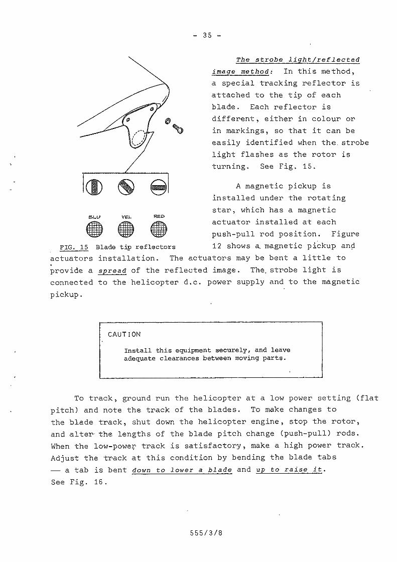
The strobe lightjreflected
ifiage method: In this method,
a special tracking reflector isattached to the tip of eachblade. Each reflector isdifferent, either in colour orin markings, so that it can beeasily identified when the.strobelight flashes as the rotor isturning. See Fig. 15.
1EBLLJ
c5EEEE?
FIG. 15 Blade tip reflectors
YEL.2-"IF;IIIIIIinn
AI JII ‘IIIIII‘Ill""=!5.
REDJuli;III‘II;III III
III‘IIII ‘III “R!
\ A magnetic pickup isinstalled under the rotatingstar, which has a magneticactuator installed at eachpush-pull rod position. Figure12 shows a_magnetic pickup and
actuators installation. The actuators may be bent a little toprovide a spread of the reflected image. The strobe light isconnected to the helicopter d.c. power supply and to the magneticpickup.
CAUTION
Install this equipment securely, and leaveadequate clearances between moving parts.
To track, ground run the helicopter at a low power setting (flatpitch) and note the track of the blades. To make changes tothe blade track, shut down the helicopter engine, stop the rotor,and alter the lengths ofWhen the low-power trackAdjust the track at this—— a tab is bent downgtg_
See Fig. 16
the blade pitch change (push~pull) rods.is satisfactory, make a high power track.condition by bending the blade tabslpweréa blade and up to raise it.
ass/3/a

....36..
TH: PAYH PLANE . ~- -- C'-.-F _ _._ i --
I (’ _*‘“ "' "' -_-_ . Q‘\~ e ‘~~ _ Kr?’-—-?+>’ “flu
Q Au mamas IN TRACK L .f
. - -~ K“l“i:~—" _->"—“ ' -\“%
‘Q ONE BLAD£ APPROX 1/2 IN. HFGH
/__1 "=—\=~=~aa-.\-,\
mimvs— couomow Cf __
. '_ c — _--I A NONEREQWRED\; ~ - .;_-_—.¢.?;:._s- -_-W’ ——‘__ B LENGTHEN PiTCH CONTROL
_ I :3" ROD {ZND OR YELLOW BLADE)
c LENGTHEN PITCH coumot _ROD emu on vcuow sums;
0NEBLADEA9PROX1/2iN.H!GH SHORTENCONTRQLRODG one sums APPROX 1 nu. LOW BRD OR RED BMDH
FIG. 16 Strobe tracking
with both the low power and the high power tracks satisfactory,the manufacturer may recommend that the track be checked in flightat various speeds and flight manoeuvres.
WARNING
When a pitch change rod is adjusted, its safetylocking must be restored to its originalcondition before the track is re—checked. Failureto do this can result in a wrecked helicopter.
Finally, you mgst check the autorotation rev/min of thehelicopter. Changes to blade angles during blade tracking can,if superimposed on previous blade angle changes, lead to anunacceptable change in the autorotation rev/min. If theserev/min are too high or too low, then the collective pitch controlsmay have to be re-rigged.
when you are strobe light blade tracking a helicopter withan articulated rotor head, you can also see how each bladelead/lag damper is performing. Any change in the spread of the .
555/3/8

, I 1 1 'r§=1Acr< - soon
, ' | 1 * TRACK - 2 Low
_ 37 _
reflected images will be caused by a change in a blade positionabout its vertical (drag) hinge. Figure 17 shows a typicalstrobe track result for a four bladed rotor.
REFLECTORS AS VIEWED i INTERPRETATION
T ii’ i 1 ’ '”i”"" “ H 1\:?TnAcK-soon ;
{I}- ._ ... 5 \I é I T DAMPERS»GOOD
_:,__
TRACK - 2 HIGH, 3 LOW
i “ — _—$°__ DAMi'»‘EFlS--GOOD
| I Ii ii DANWERS -— 3 LAGS\
i Q Ci: i: I aamweas-atass
' FIG. 17 Reflectors as viewed by strobe light and spread foridentification
You can either replace a defective damper with a serviceableone or adjust it. In each case, re—check the track to ensurethat the blades are behaving properly.
The flag method: This tracking method can be used only ifthe blades have smoothly contoured or rounded tips and if anyoptional balance weights, washers, or screws are removed from thetips for the tracking procedure. For blades with square-cut tipsthe tracking stick method should be used.
The "flag" used may be either bought from the helicoptermanufacturer or made locally from thin—walled steel tubing(automotive exhaust tubing is suitable), bungee rubber, and alightweight canvas. The base of the flag should be weighted,which makes it easier to handle. The crayons used to mark theblade tips should be good quality, fairly soft, wax crayons,and the colours used should be red, yellow, blue, black and,if needed, white. To give accurate results, the crayons shouldbe applied to the blade tips in as thin a line as possible.
The tracking procedure is different for each type ofhelicopter, and so you must refer to the maintenance manual ofthe helicopter type concerned before you do any tracking. However,a general procedure is as follows:
555/3/8

_ 33 _
Mark each blade tip with a wax crayon whose colourcorresponds with that on the blade pitch housing.
Place a strip of 25 mm (1") wide masking tape orwhite surgical tape along the forward edge ofthe tracking flag to record tracking marks.Identify the top of the tape, and make sure thatthe flag is taut on the_j@3nmg.
Head the helicopter into the wind. A light,non—gusting wind is acceptable —~ if it doesnot exceed 5 knots.
Start and warm up the helicopter.
With the collective pitch stick fully down andwith the cyclic pitch control column "leaning"into wind, carry out a low rev/min (2000 enginerev/min) l0w~power blade track.
At a signal from the pilot, lift the flag up in acounterclockwise direction —— see Fig. 18 —--andmove it very slightly into the rotor disc untileach blade tip touches the flag, leaving acoloured mark on the canvas. The sound made byeach blade tip touching the flag is distincitve,and with a little practice, just one set ofcontacts can be had.
Shut down the engine, stop the rotor, and thenadjust the blade pitch change rod lengths toreduce the blade track spread (see Pig. 18)to less than 6 mm (%"). Clean and re-mark theblade tips,'and check the track again.
When the track at low pitch and 2000 enginerev/min is satisfactory, make a track at lowpitch and take-off rev/min using the sametechnique. Make any correctionto the bladetrack at this stage by bending the bladetrailing edgegtabs (UP to raise a blade andDOWN to lower a Blade). A blade spread of notmore than Q mm (%") is acceptable.
Make a power track at take-off rev7min andwith enough power to make the helicopter"light on its skids". You may need to addballast to enable a high power setting to beused without the helicopter becoming airborne.The blade track spread should not be morethan 9 mm (%"). Adjust it by altering thelengths of the blade pitch~change rods.
when the power track is acceptable, test flythe helicopter to check the vibration leveland the autorotation rev/min.
555/3/8
_,»~- 1 ‘““““" ‘Flog movemem P i;'
m__ h_ .-"===Ir. Allmerizs 5 ,I‘ I ,1 _ 7, 0V0rlflpplng\!% A
2 -- *
= E, ,- -__.__*’_.__________ r ES‘: Q“
_ ..-___ ‘.‘§"~_‘,_A 3
. F FLAG TRACKING ‘
_ 39 -
El"*‘- i \:;._.-=¢/
Yellow markl2mm hEqh\,
itBlue and red /. -_ Bmark: overlapping ‘ '
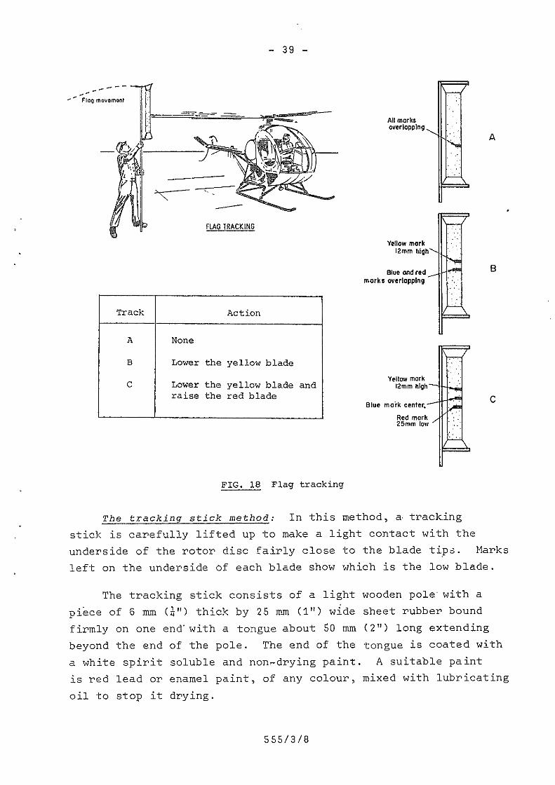
Track j Action 5\ .\ \
A 1 None iL
* B T Lower the yellow blade * \Yellow markC Lower the yellow blade and mmmnmh
raise the red blade CBlue moi'k center,
*"*"" re ea" Rd RZgmgcigv.-/r
.L.
FIG. 18 Flag tracking
The tracking stick method: In this method, a-tracking
stick is carefully lifted up to make a light contact with theunderside of the rotor disc fairly close to the blade tips. Marksleft on the underside of each blade show which is the low blade.
The tracking stick consists of a light wooden pole“with apiece of 6 mm (%") thick by 25 mm <1") wide sheet rubber boundfirmly on one end with a tongue about 50 mm (2") long extendingbeyond the end of the pole. The end of the tongue is coated witha white spirit soluble and nonedrying paint. A suitable paintis red lead or enamel paint, of any colour, mixed with lubricatingoil to stop it drying.
555/3/8

man t
marks
...L|.[]...
Tracking requires a pilot to operate the helicopter and one0 use the tracking stick.
1' Find out the power settings to be used for thetracking from the maintenance manual for thehelicopter type.
The tracker must stand under the tip path planein clear view of the pilot and face in thedirection that the rotor turns while holding thetracking stick slanted upward in the samedirection.
2.
3 Head the helicopter into wind (not more than5 knots) and warm it up.
H At a signal from the pilot, he should raisethe tracking stick carefully until the rubbertongue just contacts the blades. A furthertrack or two, may be made immediately inboard of
i the first track as checks on the first trackl
n
5 After the engine has been shut—down and therotor stopped, examine the blades for thetrack marks and adjust them to suit.
Q
6 Make another track to check the adjustmentsmade and then test fly the helicopter to checkfor vibration level and the autorotationrev/min.
I
Figure 19 shows this trackihg procedure and the blade track0
555/3/8

_ 41 _
j_'7' _ _ _:ff_7eTj*_' i ._____ ;V__;__ _V'; T7; _ 7—— _ __ _ 47 7.77 _V 7 Wj '
/1”’1 ‘_ I » A; n h _ A H/1
"“?"‘b ‘ A‘! * 4. 131*->1“ \ g 3% ’L‘ rr\.flmwmfimfiflmfifihflfifimgfl =IWWW"WMM;m ltmuhhm ’ R at‘ '.1[':*_-'- “h” g[‘II‘F__ ~.*'~.*.1.1';j Ii " ‘ '1'"- i'**’
. » ‘ ‘ -‘V -a:--“it; 1 -_ I -_ I ' . - ' i _ >=.'*'v‘“--I
ii —;_ ~
TNH3 CD ~_;.§,
_ _ . __' ”:1- V ' 1 --- _ . _3--»__- _ 'e - ___ K—K ea» _ l 7' - .
‘.9-'*
i .3 E . H?\_ \' K K K K KK T k k
Hlqh blade Low blade we mar 8(Closest trolling edge} (furthest from trolling edge)
FIG. 19 Tracking stick tracking
The rgflegtor method: This method uses the principle of"persistency of vision“, which occurs when you look along abeam of light that is being intercepted by two light reflectors.One reflector is installed at the tip of each blade. Thesurface of one reflector is plain white and the surface of theother is white with a horizontal black stripe painted across itscentre. The reflectors are illuminated by a hand~held powerfullight from the cockpit of the helicopter. A perfect track willbe seen as two equal»width white bands separated by a black band.A track with a thin white band on top will mean that the bladewith the all~white reflector is flying low.
The actual tracking procedure used is similar to the trackingflag method, except that the final tracking may be checked while thehelicopter is airborne. .
The object of blade tracking is to get a vibrationless rotor.Some combinations of rotor blades may give higher levels of Vvibration as they are brought into a close track. In this case,the lowest level of vibration should be accepted even though theblade track may be outside its specified tolerances.
555/3/8

....L[.2_-
As we have seen, the strobe light tracking method willpinpoint an unserviceable lead-lag damper, which is the usualsource of low~frequency lateral vibrations of an articulatedrotor head. The flag method cannot do this, and so a processof inspection for defects and elimination of causes will haveto be used. The rotor head and blades assembly-should beinspected for
1. Damaged blade tips and missing tip fittings.
2. Such damage to lead»lag dampers as fluid leaks,low reservoir levels, and insecure attachmentto blade or rotor hub. '
If no defects can be seen then the dampers must have theirtiming rate checked and, if necessary, adjusted. This isfollowed by a hovering and then a flight check. If the lateralvibration persists, then the rotor blades are out of balanceand need to be replaced.
Strobe light tracking, with its electronic vibrationmeasurement counterpart, can, in a few minutes, tell you howto get the blades in to track, which damper is unserviceable,and where and how much balancing weight is needed.
Main Rotor Balancing
We discussed the balancing of a main rotor using electronicvibration measuring equipment on page 24. The rotors of all typesof helicopter can be balanced (as can propellers) using thisequipment, providing the right nomogram is used. If thisequipment is not available, a persistent lateral low~frequencyvibration from an articulated rotor will show that the rotorblades need to be removed and rebalanced. This usually meansreturning the blades to the manufacturer.
The semi—rigid, two—bladed rotor is balanced after itsassembly by being placed on a special balancing mandrel set,that permits the rotor to pivot about its centre point and,usually, hold each blade grip in a definite position. The rotoris balanced:
555/3/8

h jflggifik fix
aw
....L1,3....
1- Chordwise; and
2. Spanwise.
Figure 20 shows the directions for these two balances.
ab , ' I
\G“QQ 3 8/
0
o“"‘“\\ ‘\
/\\/‘\\_
.-" .'/
.1 -\
i mynqji
~./¢<?L‘“"r-~itl
I3.
fixh*1¢
flay?“
4/J» ' 3'.' J \
c“m““'“m"‘ FIG. 20 Spanwise and chordwisebalance
Chordwise balaqge is made by firstly aligning the bladesin their grips and then moving a blade aft in its grip untilthe assembly lies level in a chordwise direction.
sganwise balance is made by adding or subtracting balanceweights from the blades until the assembly lies level in aspanwise direction.
If a lateral vibration develops in a helicopter with thistype of rotor head and an inspection has determined that therotor head is serviceable, then the rotor can be balancedwithout removing it from the helicopter by
1. Adding a small known weight to any blade andhovering the helicopter to see whether thevibration is better or worse.
2. If the vibration is better, add more weightuntil the vibration has gone.
555/3/8
_ an -
3. If it is worse, take away the added weight,install it on the other blade, and check theresult. Add more weight as needed. -
If adjusting the spanwise balance does not affect thevibration or only makes it worse, then
H. Move one blade aft in its grip by a smallmeasured amount and hover the helicopter.
5. If the vibration is less, move the same bladea little more aft until the vibration hasgone.
6. If the vibration is worse, return the bladeto its original position and move the otherblade aft by a small measured amount untilthe vibration has gone.
This sequence of balancing is only a general guide. Youmust always read and follow the directions given for balancingin the maintenance manual for the helicopter.
It is sound practice to write down the detail of eachadjustment that you make as you make it. Do not rely upon yourmemory.‘ You must always make good all locking devices andtorque all nuts/bolts after making each adjustment.
Tail Rotor Tracking and Balancing
Even a small degree of imbalance in a tail rotor, either ofweight or of blade track, is unacceptable because of the high-frequency vibration it can generate. Before you begin anytail rotor balancing or tracking, you must closely examinethe complete installation for damage and wear. (See page 31,)
555/3/8

_ 45 _
Tail Rotor Balancing
Tail rotor blades may be supplied as a matched set, asindividual blades balanced to a master blade, or as individualblades that you will have to balance to the existing blades.How they are supplied varies from manufacturer to manufacturer,although the matched set seems to be the most popular way.
After you have assembled the tail rotor, you can balanceit on a balancing fixture. The two—bladed rotor is usuallybalanced, like the semi~rigid main rotor, in both chordwiseand spanwise directions. However, some tail rotors are balancedon the helicopter, in which case, great care must be takenduring the first run—up that an excessive vibration does notdevelop and cause damage.
Tail rotors may be balanced using the electronic vibrationmeasurement equipment. See page 22 and Fig. 21, where the angleread from the protractor assembly and the vibration level inmils from the vibration analyser dial are put into a balanceweight location chart supplied by the helicopter manufacturer.You then fit the balance weights indicated and check the result.
Zero angle Ilne ix Qygiiagiawed on
‘ / Biuebiude
_~_“‘ -er i, _.mi.19¢.-, ..
I»
_ Protroctorf \/]brqp|°n V assembly and strobe
analyser fix; "QM‘I .. _. ""¢v»'
eat0
‘I Strobe llqhl box ‘ZQVDC P0wer ~~euppiy‘ _
FIG. 21 Tail rotor balancing
3F’-\\\ ,xi,
X
_
555/3/8

_ 45 i
As with main rotor balancing, you must always follow thedirections given for tail rotor balancing in the maintenancemanual for the helicopter.
Tail Rotor Blade Tracking.
Tracking of tail rotor blades is now almost a thing of thepast. At one time, the blades were tracked by the "trackingstick" method, where the tracking stick was brought to theside of-the blade disc nearest to the tail boom. This preventedthe operator from falling into the disc, and the tail boom madea convenient rest for the tracking stick. However, unlessthis tracking was done with the greatest of care, you were likelyto get damaged tail rotor blades or tracking marks that were ofno use at all.
when a tail rotor is out of track, you will see a "fuzzy"tip when viewing the turning rotor from directly in front or frombehind. You will also feel a high-frequency vibration in theairframe. If you are unsure of the vibration, you can observe,or feel, the trailing edge of the nearby horizontal stabiliser,or else you can increase the tension of the tail rotor controlcables for the duration of a test hover and feel the tail rotorpedals for abnormal vibration. If the tail rotor has only twoblades and adjustable pitch change links, then altering thelength of one link will move that blade either further out oftrack or else back into track. Should the fuzzy tip appearthicker, then the blade is further out of track, and the pitchchange link should be reset to its original length, plus a littleextra in the opposite direction. Adjustable pitch change linksare usually altered in "half turns" of a rod end, making it easyto keep a check of the exact adjustment made. when you havecompleted tracking, test fly the helicopter and check the vibrationlevel and the response of the tail rotor.
Many tail rotors do not have adjustable pitch change rods,so an out-of-track condition will be due either to an accumulationof tolerances in the control linkages to the blades or to theblades themselves.
553/3/8

_ u7 _
Finally, tail rotor blade tracking is done at the same timeas tail rotor balancing, as both are closely related, and thejob must be done strictly according to the instructions in themaintenance manual for the helicopter type concerned.
DRIVE SHAFTS AND COOLING FANS
All drive shafts and cooling fans are potential sources ofhigh-frequency vibration. The causes of the vibration can be
1. An out-of-balance condition of a drive shaftor a cooling fan,
2. Defective drive shaft bearings,
3. Misalignment of a drive shaft,
H. Looseness of attachment, or
5. Rarely, a foreign object, such as a piece ofrag rotating,with the fan or drive shaft.
An outeof-balance condition: This can be found by usingelectronic vibration measuring equipment, although you must becareful not to confuse a high-frequency vibration with one fromthe tail rotor.
Defectjygfdriye shaft bearings: A defective bearing may
run hot and may be noisy. Carefully feeling each bearing forheat and listening to each one, with a sounding rod, whilethe helicopter is running will often pinpoint a poor bearing.The condition of the grease in a greased or grease—packed bearingwill often give an indication of the condition of a bearing.
- Misalignmentiofma drive shaft: Misalignment can often beseen quite easily-by looking along the shaft. Structuraldamage of the airframe can cause misalignment, and a thoroughvisual inspection of the airframe should be made if this defectis suspected.
555/3/8

can be found by visual inspection and by checking the torqueLooseness of attachment and the presence Qfjforeign objects
- we --
of securing bolts and nuts.
rebalanced or replaced.‘ Defective bearings and misaligned driveshafts will have to be aligned using the methods specified
Components that are out of balance will have to be either
»
the helicopter maintenance manual.
damage caused by its looseness and determine whether the loosenesscaused the vibration or vice versa. Remove foreign objects andcheck for damage. For example, a piece of rag can score a driveshaft
If a component has worked loose, you must look for any
‘ SUMMARY
Do not use together rotor blades with greatly differentflying hour ages, even though they may be of thecorrect type.
Always follow the manufacturer's instructions for rotortracking and balancing.
An experienced pilot should be at the controls duringbladeitracking and balancing.
Strobe light/reflected image is the preferred methodof'blade.tracking.
Autorotation rev/min must be checked after bladetracking is finished.
Control rods must be safetied after they-have beenadjusted and*before a blade track is made.
PRACT ICE EXERCISE C
In each of the.following, choose the option thatcorrectly completes the statement; writing A, B,C or D as your answer.
555/3/8

_L|.Q...
Flag tracking should not be done when the windspeed is in excess of
A. 5 knots
B. 10 knots
C. 15 knots
D. 20 knots
The object of tracking a main rotor blade is togive
A. All blades flying in the same path
B. The smoothest running rotor
C. The correct autorotation rev/min
D. The best performance from the rotor
The tracking method that will show up improperlytimed blade dampers is
A. The tracking stick method
B. The reflector method
C. The strobe light method
D. All of A, B, and C
A semi-rigid rotor is balanced:
A . Spanwise
B, Chordwise
C. Spanwise and tracked
D. Spanwise and chordwise
5. An out-of—balance tail rotor can be indicatedby:
A. A high frequency vibration
B. A fuzzy appearance of the blade's tip paths
C. A high frequency vibration felt in the tailrotor control pedals
D. All of A, B, and C
(Answers on page 50)
555/3/8
EXERCISE A
1.
2.
3.
4.
EXERCiSE B
Statements 2,
1 is
8 is
H is
5 is
7 is
10 is
EXERCISE C
1.
2.
3.
H.
5.
Answer
Answer
AnswerAnswer
False,
False,
False,
False,
False >
False,
Answer
Answer
Answer
Answer
Answer
_ 50 _
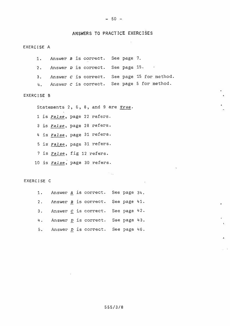
ANSWERS TO PRACTICE EXERCISES
B is
D is
C is
c is
5,
Page
page
Page
Page
correct
correct
correctcorrect
. See
. See
. See
. See
page 7.
page 15. -
page 15 for methodpage 5 for method.
8, and 9 are True.
22 refers.
28 refers.
31 refers.
81 refers.
fig 12 refers.
page 30 refers.
5 is
§ is
Q is
Q is
Q is
correct
correct
correct
correct
correct
. See
. See
. See
. See
. See
555/3/8
page 3%.
page H1.
page H2.
page H3.
page H6.

_ 51 _
TEST PAPER 8
NOTE: Questions 1 to 10 in this test paper can be answered inno more than 50 words for each answer.
What damage does vibration do to a tail rotor controloperated by a cable and push rod system?
What single word is used for "the speed of vibration",and what SE unit is used to represent it?
Name three different units of measurement used togive the amplitude of a vibration.
Give the two general sources of vibration in ahelicopter.
Why does misalignment of a drive shaft cause_vibration?
What are the three ranges of vibration of a helicoptercalled? Give one cause of vibration in each range.
What are the two possible choices of action availablewhen a helicopter enters ground resonance? Statewhen each choice should be made. '
The main rotor head lead~lag dampers are serviceable,and yet the helicopter gets into ground resonanceeasily. What components would you suspect as beingunserviceable, and what would you expect to find wrongwith them?
Explain why autorotation rev/min should be checkedafter adjustments have been made to the track ofthe main rotor blades.
558/3/8

_ 52 _
During a blade tracking procedure, why must a rotorblade pitch change be safetied after it Eas beenadjusted and before any test flight?
Refer to Fig. 13. >The clock angle light is on at"quarter past nine" on the 0.25 IPS circle. Whatbalance weights should be used, and where should theybe fitted to achieve balance?
i
Make a freehand sketch, showing clearly the directionsfor spanwise and chordwise balance of a two—blade rotor
Make a freehand sketch showing a three—bladed rotorstrobe track with one blade low in track and anotherblade lagging.
Refer to Fig. 1H.
(a) What is the frequency of the O.H IPS vibration?
(b) If the rotor has two blades, what are its rev/minif the vibration in (a) is a "1 per rev"?
TABLE 2
4%‘ Sp§eds_(rev/min) _
Main Rotoi Tail Rotor Engine T/R Drive Shaft
24 1654 6600 4300
From the drive speeds given in Table 2 for a helicopterwith a semi-rigid, two-bladed main rotor and two~bladedtail rotor, calculate the vibration frequency of
Ga) A main rotor "1 per rev"
€b) An out-of~balance tail rotor
555/3/8

_ 53 i
(c) The normal engine vibration
(d) A vibration from the tail rotor gear—box input pinionthat has 5 damaged teeth.
-&""‘3-?"@'A~
555/3/a

W,i
_Ԥ
__
W’I_‘*
_4‘fl____‘_‘i_;i_’§_