08nors006 central tt-1...mp 49.8 tc to mp 48.2 tc, through click siding 20 mp 48.2 tc, through...
TRANSCRIPT
CENTRAL DIVISIONWestern Region
Timetable Number
1In Effect
At 12:01 AM
Monday, August 4, 2008
Eastern Daylight Savings Time
For The Government of Employees Only

COMMITTED TO SAFETY
DOUBLE ZEROS
ZERO INJURIES ZERO INCIDENTS
COMMUNICATION IS THE KEY

CENTRAL DIVISION TIMETABLE
TABLE OF CONTENTS
I. Timetable General Information ..................................................... 1
a. Station Page .......................................................................... 1 b. Explanation of Characters .................................................... 1 c. Diesel Unit Groups ................................................................ 2 d. Main Track Control ................................................................ 2 e. Division Special Instructions ................................................. 2
II. Central Division Station Pages ..................................................... 3
III. Central Division Special Instructions ............................... 173–184

This page is intentionally left blank.

1
CENTRAL DIVISION TIMETABLE
GENERAL INFORMATION
A. STATION PAGEEach station page will contain the following information:1. Rules in Effect2. Maximum Speeds3. Checking Locomotive Speed Indicator4. Diesel Unit Ratings5. Locomotive and Car Restrictions6. Switches and Derails7. Communication Information8. Detector Instructions9. District Instructions
B. EXPLANATION OF CHARACTERSSymbols: — Automatic Interlocking — Controlled Interlocking — Controlled PointCS — Controlled Siding — Dispatcher Radio Call-in Code — DrawbridgeFrt. — Freight TrainsJct. — Junction — Non-Interlocked Railroad Crossing at GradeN/S — Non-Signaledr — Radio Base Station, WaysideR — Radio Base Station, Monitored-ContinuouslySS — Signaled Sidingss — Spring SwitchS — Stop SignY — Wye — Yard Limit
Train Inspection Detectors:DED — Dragging Equipment DetectorHCD — High Car Detector (includes Excessive Height Detectors)HBD — Hot Box Detector (includes TSA, SAD and HBD detectors)HWD — Hot Wheel DetectorWCD — Wide Car DetectorSSD — Stress State DetectorSWD — Sliding Wheel Detector
All train inspection detectors are listed on the station pages according to milepost location. Unless otherwise indicated, train inspection detectors are Radio Alarm and operate in both directions on single or multiple track.
Detectors on Single Track — Track will not be shown.
CP
YL
999
DB

2
CENTRAL DIVISION TIMETABLE
GENERAL INFORMATION (CONT.)
C. DIESEL UNIT GROUPSGROUP 1 = B-23-7, GP-38, GP-38-2, GP-38-AC, GP-40 2 = B-30-7A, B-36-7, B-40-2, D8-32-B, GP-40X, GP-49, GP-50,
GP-59, GP-60 3 = C-30-7, SD-40, SD-40-2 4 = C-36-7, SD-50 5 = C-39-8, D8-40-C, D9-40-C, D9-40-CW, SD-60, SD-70 6 = C-44-AC, C-60-AC, C-90-AC, SD-70-MAC, SD-80, SD-80-MAC,
SD-90-MAC
D. MAIN TRACK CONTROLUnless otherwise noted on the station pages, the Train Dispatcher/Control Operator controls all Main Tracks, Controlled Points, and Controlled Interlockings.
E. DIVISION SPECIAL INSTRUCTIONSAll Central Division Special Instructions have reference to a rule and are numbered or lettered as shown in the following examples:
CE-GR-13-1 — Refers to NS Operating Rule GR-13. CE-L-236-1 — Refers to NS-1 Rule L-236. CE-1110(b)-1 — Refers to NS Safety and General Conduct Rule 1110(b).
NOTE: • General Rules and General Regulations (GR) can be found in both the NS Operating Rules and the Safety and General Conduct Rule Books.
• NS Operating Rules are Numbered 999 and below. Safety and General Conduct Rules are numbered 1000 and up.
• CE indicates the Special Instruction is specific to the Central Division.
3
CENTRAL DIVISION TIMETABLE
STATION PAGES
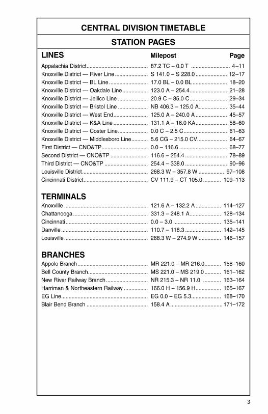
LINES Milepost Page
Appalachia District ......................................... 87.2 TC – 0.0 T .......................... 4–11Knoxville District — River Line ...................... S 141.0 – S 228.0 ..................... 12–17 Knoxville District — BL Line .......................... 17.0 BL – 0.0 BL ....................... 18–20 Knoxville District — Oakdale Line ................. 123.0 A – 254.4 ......................... 21–28 Knoxville District — Jellico Line .................... 20.9 C – 85.0 C ......................... 29–34 Knoxville District — Bristol Line .................... NB 406.3 – 125.0 A ................... 35–44 Knoxville District — West End ....................... 125.0 A – 240.0 A ..................... 45–57 Knoxville District — K&A Line ....................... 131.1 A – 16.0 KA ..................... 58–60 Knoxville District — Coster Line .................... 0.0 C – 2.5 C ............................. 61–63Knoxville District — Middlesboro Line ........... 5.6 CG – 215.0 CV .................... 64–67 First District — CNO&TP ............................... 0.0 – 116.6 ................................ 68–77 Second District — CNO&TP ......................... 116.6 – 254.4 ............................ 78–89Third District — CNO&TP ............................. 254.4 – 338.0 ............................ 90–96 Louisville District ............................................ 268.3 W – 357.8 W ................. 97–108 Cincinnati District ........................................... CV 111.9 – CT 105.0 ............ 109–113
TERMINALSKnoxville ........................................................ 121.6 A – 132.2 A ................. 114–127 Chattanooga .................................................. 331.3 – 248.1 A ..................... 128–134 Cincinnati ....................................................... 0.0 – 3.0 ................................ 135–141 Danville .......................................................... 110.7 – 118.3 ........................ 142–145 Louisville ........................................................ 268.3 W – 274.9 W ............... 146–157
BRANCHESAppolo Branch ............................................... MR 221.0 – MR 216.0 ........... 158–160 Bell County Branch ........................................ MS 221.0 – MS 219.0 ........... 161–162New River Railway Branch ............................ NR 215.3 – NR 11.0 ............ 163–164Harriman & Northeastern Railway ................ 166.0 H – 156.9 H ................. 165–167EG Line .......................................................... EG 0.0 – EG 5.3 .................... 168–170 Blair Bend Branch ......................................... 158.4 A ................................... 171–172

4
APPALACHIA DISTRICT WEST SIDINGS IN FEET MP STATION NOTE
EAST END DISPATCHER ...........................................
87.2 TC JUSTICE ...................................................................... Y
86.8 TC HAUN .............................................................................
86.3 TC WARD ..........................................................................R
85.4 TC MOORE .........................................................................
82.3 TC SUMMIT .........................................................................
80.4 TC HBD-DED (Otes)
75.5 TC MCCLOUD .....................................................................
73.2 TC HOGAN ..........................................................................
71.9 TC HBD-DED (Burem)
70.0 TC BUREM ........................................................................R
65.1 TC HAWKINS ......................................................................
63.4 TC SURGOINSVILLE ..........................................................
61.1 TC HBD (Stoney Point)
54.2 TC CHURCH HILL ..............................................................
49.8 TC LAMB .............................................................................
48.2 TC CLICK ............................................................................
47.5 TC HBD (Frisco)
46.3 TC FRISCO ...................................................................R, r
43.8 TC YUMA ............................................................................
42.0 TC SMITH ..........................................................................R
35.2 T HBD-DED (Gate City)
34.1 T BOONE ..........................................................................
32.4 T WATKINS .....................................................................R
24.5 T GLENITA .....................................................................R
21.4 T HBD (Sunbright)
16.3 T TITO .............................................................................R
15.1 T JASPER .........................................................................
10.1 T HBD-DED (Oreton)
3.4 T BIG STONE ......................................................... R
POCAHONTAS DIVISION DISPATCHER ...................
1.0 T APPALACHIA .............................................................. Y 1
0.0 T ANDOVER .....................................................................
15734
9180
7300
A LINE
BL LINE
CSXT CSXT
9192
6592
6551
CSXT
SS
CP
772
SS
SS
SS
SS
SS
CP
CP
CP
CP
CP
CP
CP
CP
CP
CP
CP
CP
CP
CP
CP
CP
CP
CP
CP
CPYL
YL
626
YL
CP

5
APPALACHIA DISTRICT
STATION PAGE INFORMATIONNOTE 1: Pocahontas Division Timetable governs between Big Stone and Andover.
1. RULES IN EFFECT Main 1 TrackBetween RulesJustice and Big Stone 261 Big Stone and Andover 93

6
APPALACHIA DISTRICT
2. MAXIMUM SPEEDS Main TrackBetween MPHMP 87.2 TC, Justice and MP 85.4 TC, Moore 20 Except: MP 87.2 TC to MP 87.0 TC, Curves 10MP 85.4 TC, Moore and MP 40.0 TC, Moccasin Gap 50 Except: MP 85.4 TC, Through Turnout Moore 20 MP 85.4 TC to MP 82.3 TC, Through Summit Siding 20 MP 85.4 TC to MP 82.0 TC, Curves 35 MP 82.3 TC, Through Turnout Summit 20 MP 82.0 TC to MP 76.8 TC, Curves 40 MP 76.8 TC to MP 76.5, TC 35 MP 76.5 TC to MP 75.7 TC, Curves 40 MP 75.7 TC to MP 70.9 TC, Curves 45 MP 70.9 TC to MP 70.1 TC, Curves 40 MP 70.1 TC to MP 68.1 TC, Curves 45 MP 68.1 TC to MP 66.7 TC, Curves 40 MP 66.7 TC to MP 66.0 TC, Curves 35 MP 66.0 TC to MP 62.7 TC, Curves 40 MP 65.1 TC, Through Turnout Hawkins 20 MP 63.4 TC, Surgoinsville and MP 65.1 TC, Hawkins on Siding 20 MP 63.4 TC, Surgoinsville, Through Turnout 15 MP 62.7 TC to MP 58.1 TC, Curves 35 MP 57.2 TC to MP 54.6 TC, Curves 45 MP 54.6 TC to MP 51.0 TC, Curves 40 MP 51.0 TC to MP 50.5 TC, Curves 35 MP 50.5 TC to MP 40.2 TC, Curves 30 MP 49.8 TC, Through Turnout Lamb 20 MP 49.8 TC to MP 48.2 TC, Through Click Siding 20 MP 48.2 TC, Through Turnout Click 20 MP 46.5 TC, Through Turnout Frisco and CSXT New Connection Track 20 MP 46.3 TC, Through Turnout Frisco and CSXT Old Connection Track 10 MP 40.2 TC to MP 40.0 TC, Curves 25MP 40.0 TC, Moccasin Gap and MP 0.0 T, Andover 40 Except: MP 40.0 T to MP 38.6 T, Curves 30 MP 34.3 T to MP 32.1 T, Curves 30 MP 34.1 T, Through Turnout Boone 20 MP 34.1 T to MP 32.4 T, Through Boone Siding 20 MP 32.4 T, Through Turnout Watkins 20 MP 32.1 T to MP 27.7 T, Curves 25 MP 27.7 T to MP 24.3 T, Curves 20 MP 24.3 T to MP 24.1 T, Curves 15 MP 24.1 T to MP 22.6 T, Curves 20 MP 22.6 T to MP 18.9 T, Curves 25 MP 18.9 T to MP 14.8 T, Curves 35 MP 16.3 T, Through Turnout Tito 20 MP 16.3 T to MP 15.1 T, Through Tito Siding 20 MP 15.1 T, Through Turnout Jasper 20 MP 14.8 T to MP 11.6 T, Curves 30 MP 11.6 T to MP 5.6 T, Curves 25 MP 5.6 T to MP 3.4 T, Curves 30 MP 0.6 T to MP 3.4 T 20 MP 0.0 T to MP 0.6 T 10

7
APPALACHIA DISTRICT
3. CHECKING LOCOMOTIVE SPEED INDICATORTests for accuracy will be made at the following locations and Engineers will adjust speed in accordance with any inaccuracy.
LOCATION OF TEST MILE SIGNS: WESTWARD EASTWARD MP 84.0 TC to MP 83.0 TC MP 52.0 TC to MP 51.0 TC MP 38.0 T to MP 37.0 T MP 4.0 T to MP 3.0 T
NOTE: Tests for accuracy will be made at other locations in addition to those shown. Engineers will choose appropriate locations to check speed indicators.
4. DIESEL UNIT RATINGS DIESEL UNIT RATINGS IN TONS Group 1 Group 2 Group 3 Group 4 Group 5 Group 6
WestwardBulls Gap to Yuma 2200 2950 3500 4365 4850 5720Yuma to Andover 1100 1450 1750 2160 2400 2830Bulls Gap to St. Paul 2200 2950 3500 4365 4850 5720
EastwardAndover to Yuma 1300 1750 2050 2565 2850 3360Yuma to Bulls Gap 3550 4750 5650 7020 7800 9200St. Paul to Bulls Gap 3550 4750 5650 7020 7800 9200

8
APPALACHIA DISTRICT
5. LOCOMOTIVE AND CAR RESTRICTIONS
A. WEIGHT RESTRICTIONSLoaded 4-axle cars may be handled up to the weight shown provided the stenciled Load Limit (Weight of car and lading) is NOT exceeded. 286,000 lbs.
B. EQUIPMENT RESTRICTIONSTrailing tonnage must be limited on line segments as shown below, behind the following equipment:1. Empty Multi-level cars.2. Empty Intermodal single-platform flats and such loaded with empty trailers or
containers.3. Empty 85-foot-long or longer flats and such flat cars when loaded with empty
trailers or containers, or loaded with only one (1) trailer or container.4. Empty Intermodal single-axle truck flat car or such cars loaded with empty
trailers or containers.5. Empty single or multiple-unit double-stack (well) cars, or articulated single-
platform (spine) cars. Be governed by Appendix 1 in the System Timetable.
Maximum Safe Trailing Tonnage Southward/ Northward/ Line Segments Between Westward EastwardAppalachia Line Andover and Yuma Rear Only Rear Only Yuma and Bulls Gap 10,000 10,000
6. SWITCHES AND DERAILS
JUNCTIONS INTERLOCKED
Milepost Location Line/R.R. 87.2 TC Justice A Line 86.3 TC Ward BL Line46.3 TC Frisco CSXT 3.4 T Big Stone CSXT
NON-INTERLOCKED Milepost Location Line/R.R. 1.0 T Appalachia TB Line, Pocahontas Division
7. COMMUNICATION INFORMATION Channel 1 Channel 2 Base Station TX and RX TX (RX)Big Stone 56 NATito 56 NASunbright 56 NACopper Creek 56 NAGate City 56 NAFrisco 56 NABurem 56 NABulls Gap 56 NA

9
APPALACHIA DISTRICT
8. DETECTOR INSTRUCTIONSNone.
9. DISTRICT INSTRUCTIONS
A. EXCESSIVE CURVATURE Listed below are tracks with curvature of 12 degrees, 30 minutes or greater:
Milepost Location Curvature 18.9 T Gilbert Wood 19.5 degrees 46.5 TC Eastman Chemical 19.0 degrees Refer to the Equipment Restriction Section of the System Timetable.
B. JOINT TRACKAGE 1. Trains and engines of the Central Division will use tracks of other divisions and
foreign lines in accordance with their Timetables, Rules, and Regulations as shown below:
(a) Between Andover Yard, MP 0.0 T and Big Stone, MP 3.4 T, Pocahontas Division.
(b) Between St. Paul, VA, MP 42.2 Z to Kingsport, TN, MP 95.0 Z, CSXT.
2. Trains and engines of other divisions and foreign lines will use Central Division tracks as shown below:
(a) Between Big Stone, MP 3.4 T and Frisco, MP 46.3 TC, CSXT. (b) Between Big Stone, MP 3.4 T and Justice, MP 87.2 TC,
Pocahontas Division.
C. PUSHER SERVICE The equivalent of 24 conventional powered axles may be used in pusher service on the Appalachia District between Andover and Watkins.
D. POCAHONTAS NA TRAIN DISPATCHER To access the Pocahontas NA Train Dispatcher, use 626 to set up the radio on a normal call-in.

10
APPALACHIA DISTRICT
9. DISTRICT INSTRUCTIONS
E. BULLS GAP 1. Close clearance exists on both ends of Bulls Gap Yard.
2. Conductors on trains setting off, picking up, and/or switching at Bulls Gap will advise the East End Dispatcher and CYO of cars set off and/or picked up for each track affected.
3. Conductors will advise the East End Dispatcher and CYO of any hazardous material cars set off at Bulls Gap and be governed by instructions received on where to leave shipping papers.
4. Derails are located on east leg of Wye, MP 86.9 TC and upper yard (Knox. End) MP 86.8 TC, Bulls Gap.
5. The normal position for Wye switch TC Line will be lined and locked for move-ment on west leg of Wye.
6. The following road crossings on the BL Line must not be blocked: Sycamore (Hotel Crossing) — MP 0.6 BL County Line — MP 0.9 BL White Horn Creek — MP 1.2 BL
Westward trains en route to Bulls Gap on the BL Line will notify the Knoxville East End Dispatcher as they pass Lowland and will hold back east of White Horn Crossing, MP 1.2 BL until advised by the Train Dispatcher that he/she is ready for the train. Additionally, if unexpected delay is experienced approaching Bulls Gap, the above crossings must be cut.
7. All trains will carry 100 pounds train line pressure, except Trains T50T1 (Frisco Switcher), T52T1, T58/T59, (Sevier-Bulls Gap Locals) and T62T1 (Kingsport Switcher) are exempt from these instructions and will carry standard train line pressure of 90 pounds.
8. At the following locations when switching with 10 or more cars, air must be cut in on at least half of the cars being handled:
(a) Frisco to old CSXT connection track. (b) Greenland Lead between Gate and Storage track. (c) Click (East End).

11
APPALACHIA DISTRICT
9. DISTRICT INSTRUCTIONS (CONT.)
F. BUREM Trains weighing at Burem, TN, MP 70.0 TC: 1. When engines are approximately 300 feet from the scale, the scale will turn on
automatically.
2. A Yellow light, located on scale building, will come on when scale is “ON” and in weigh mode. While weighing, train speed should not exceed 8 MPH. If speed is in excess of 8 MPH, the light will flash along with an intermittent tone, which will sound via radio. When this occurs, speed should be reduced immediately. Sixty seconds after last car in train clears the scale an extended tone will sound via radio.
G. FRISCO 1. Do not exceed 10 MPH over Bridges No. 33 and No. 35, Holston Army
Ammunition Plant, CSXT MP Z 93.0. These bridges are located in the plant in the area know as the “XYZ” part of Area “B”.
2. Natural Tunnel State Park, MP 24.3 T has installed floodlights at the Observation Platform to illuminate the entrance to the tunnel. These lights will be used during early evening hours, approximately two (2) to three (3) times per month.
H. END-OF-TRAIN DEVICE — GRADESReference the identification of grades as required in NS-1 Rules for Equipment Operation and Handling, Rule A-31, End-Of-Train Device and revised NS-1 Rule L-241, to include instructions for descending grades of 1% or more.
In accordance with CFR Part 232, the following designated sections of track are identi-fied as average grades of:
2% or greater over a distance of 2 continuous miles or 1% or greater over a distance of 3 continuous miles:
APPALACHIA DISTRICT
Eastward Westward MP 10.5 T to MP 17.0 T = 1.28% MP 10.5 T to MP 5.0 T = 1.29% MP 21.6 T to MP 25.3 T = 1.34% MP 32.4 T to MP 28.3 T = 1.50% MP 32.4 T to MP 35.4 T = 1.07%

12
KNOXVILLE DISTRICT RIVER LINE
WEST SIDINGS IN FEET MP STATION NOTE
PIEDMONT DIVISION DISPATCHER .........................
S 141.0 ASHEVILLE ............................................................ R, Y 1
S 142.3 MURPHY JCT. ..............................................................
EAST END DISPATCHER ...........................................
S 145.9 CRAGGY .......................................................................
S 152.3 HBD-DED (Alexander)
S 157.3 VOLGA ..........................................................................
S 159.7 IVY .................................................................................
S 163.3 Marshall .......................................................................... R
S 163.8 HBD-DED-HWD (Marshall)
S 166.3 NOCONA .......................................................................
S 168.3 WALNUT ........................................................................
S 170.9 DED 2
S 178.9 HBD-DED (Hot Springs)
S 180.1 HOT SPRINGS ............................................................R
S 182.7 FRENCH ........................................................................
S 182.7 DED 2
S 189.1 Wolf Creek ...................................................................... R
S 191.1 HBD-DED-HWD (Wolf Creek)
S 193.9 DEL RIO ........................................................................
S 195.1 BIG CREEK ...................................................................
S 200.7 BRIDGEPORT ...............................................................
S 202.9 HUFF .............................................................................
S 203.3 HBD-DED (Bridgeport)
S 206.4 Newport .......................................................................... R
S 210.8 HBD-DED (Newport)
S 213.5 LEADVALE ....................................................................
S 215.5 LILAC ............................................................................
S 216.5 DOUGLAS .....................................................................
S 223.8 HBD-DED (Roe Jct.)
S 228.0 NEW LINE .....................................................................
2 1
10241
10234
12235
7197
10097
10263
A LINE
BL LI
NE
CP
336
YL
772
CP
CP
CP
CP
CP
CP
CP
CP
CP
CP
CP
SS
SS
SS
SS
SS
SSCP
CP
CP
CP

13
KNOXVILLE DISTRICT RIVER LINE
STATION PAGE INFORMATIONNOTE 1: Piedmont Division Timetable governs between Murphy Jct and Asheville.NOTE 2: Voice alarm only.
1. RULES IN EFFECT Main Main 1 Main 2 Track Track TrackBetween Rules Asheville and Murphy Jct. 261 261 Murphy Jct. and Craggy 261 261 Craggy and New Line 261
2. MAXIMUM SPEEDS Main TracksBetween MPHMP S 141.0, Asheville and MP S 228.0, New Line 50 Except: MP S 138.2 to MP S 142.3 20 MP S 142.3 to MP S 143.0, Curves 30 MP S 143.0 to MP S 148.6, Curves 35 MP S 145.9, Through Turnout Craggy 40 MP S 148.6 to MP S 164.9, Curves 30 MP S 164.9 to MP S 166.2, Curves 25 MP S 166.2 to MP S 166.8, Curves 20 MP S 166.8 to MP S 167.4, Curves 25 MP S 167.4 to MP S 172.2, Curves 30 MP S 172.2 to MP S 177.1, Curves 25 MP S 177.1 to MP S 177.9, Curves 20 MP S 177.9 to MP S 178.2, Curves 15 MP S 178.2 to MP S 182.1, Curves 30 MP S 182.1 to MP S 182.5, Curves 25 MP S 182.5 to MP S 186.5, Curves 30 MP S 186.5 to MP S 188.0, Curves 25 MP S 188.0 to MP S 191.3, Curves 35 MP S 191.3 to MP S 195.4, Curves 40 MP S 195.4 to MP S 197.5, Curves 30 MP S 197.5 to MP S 198.2, Curves 25 MP S 198.2 to MP S 198.6, Curves 20 MP S 198.6 to MP S 203.3, Curves 35 MP S 203.3 to MP S 204.3, Curves 30 MP S 204.3 to MP S 206.7, Curves 35 MP S 206.0 to MP S 207.0, Over Street Crossings 30 MP S 206.7 to MP S 208.3, Curves 40 MP S 208.3 to MP S 216.8, Curves 45 MP S 216.5, Through Turnout Douglas 40 MP S 216.8 to MP S 217.3, Curves 40 MP S 217.3 to MP S 224.6, Curves 35 MP S 224.6 to MP S 225.4, Curves 30 MP S 225.4 to MP S 228.0, Curves 35 MP S 228.0/MP 91.4 A, Through Turnout New Line 40 MP S 228.0/MP 91.4 A, Through Crossover New Line 25Auxiliary Tracks: All Industry Tracks, Asheville Terminal 5

14
KNOXVILLE DISTRICT RIVER LINE
3. CHECKING LOCOMOTIVE SPEED INDICATORTests for accuracy will be made at the following locations and Engineers will adjust speed in accordance with any inaccuracy.
LOCATION OF TEST MILE SIGNS: WESTWARD EASTWARD MP S 147.0 to MP S 148.0 MP S 211.0 to MP S 210.0 MP S 151.0 to MP S 152.0
NOTE: Tests for accuracy will be made at other locations in addition to those shown. Engineers will choose appropriate locations to check speed indicators.
4. DIESEL UNIT RATINGS DIESEL UNIT RATINGS IN TONS Group 1 Group 2 Group 3 Group 4 Group 5 Group 6
WestwardAsheville to Leadvale 2150 2900 3450 4230 4700 5550 Leadvale to New Line 1650 2200 2650 3240 3600 4250
EastwardNew Line to Bridgeport 2150 2850 3450 4230 4700 5550 Bridgeport to Asheville 2300 3100 3650 4545 5050 5960
5. LOCOMOTIVE AND CAR RESTRICTIONS
A. WEIGHT RESTRICTIONSLoaded 4-axle cars may be handled up to the weight shown provided the stenciled Load Limit (Weight of car and lading) is NOT exceeded. 286,000 lbs.
B. EQUIPMENT RESTRICTIONSTrailing tonnage must be limited on line segments as shown below, behind the following equipment:1. Empty Multi-level cars.2. Empty Intermodal single-platform flats and such loaded with empty trailers or
containers.3. Empty 85-foot-long or longer flats and such flat cars when loaded with empty
trailers or containers, or loaded with only one (1) trailer or container.4. Empty Intermodal single-axle truck flat car or such cars loaded with empty
trailers or containers.5. Empty single or multiple-unit double-stack (well) cars, or articulated single-
platform (spine) cars. Be governed by Appendix 1 in the System Timetable.
Maximum Safe Trailing Tonnage Southward/ Northward/ Line Segments Between Westward EastwardRiver Line Asheville and New Line 7,000 Rear Only

15
KNOXVILLE DISTRICT RIVER LINE
6. SWITCHES AND DERAILS
A. JUNCTIONS INTERLOCKED
Milepost Location Line/R.R. S 142.3 Murphy Jct. Piedmont Division S 216.5 Douglas BL Line S 228.0 New Line A Line
B. LOCATIONS WHERE TRAINS MAY NOT CLEAR Hand-operated switches at the following locations are not equipped with electric locks. Trains and engines must not clear on these tracks (does not apply to M/W equip-ment): Location Switch MP S 227.7 Stewart Lumber MP S 218.4 Hamblen County Co-op
These switches must not, at any time, be used to clear the Main Line at any of these tracks. While using these tracks, an engine or car must continuously occupy the Main Track or the Main Track switch must be kept continuously set for movement into such track.
7. COMMUNICATION INFORMATION Channel 1 Channel 2 Base Station TX and RX TX (RX)Asheville 56 48 (9)Marshall 56 48 (9)Hot Springs 56 48 (9)Wolf Creek 56 48 (9)Newport 56 48 (9)
8. DETECTOR INSTRUCTIONSNone.

16
KNOXVILLE DISTRICT RIVER LINE
9. DISTRICT INSTRUCTIONS
A. JUNCTIONS INTERLOCKED
Milepost Location Line/R.R. S 142.3 Murphy Jct. Piedmont Division S 216.5 Douglas BL Line S 228.0 New Line A Line
B. JOINT TRACKAGE 1. Trains and engines of the Central Division will use tracks of other divisions and
foreign lines in accordance with their Timetables, Rules, and Regulations as shown below:
Between Asheville, MP S 139.0 and Murphy Jct., MP S 142.3, Piedmont Division.
2. Trains and engines of other divisions and foreign lines will use Central Division tracks as shown below:
NONE
C. JOINT TRACK AUTHORITY IS REQUIRED AT THE FOLLOWING LOCATIONS:
Between Craggy, MP S 145.9 and Murphy Jct., MP S 142.3(Central Division East End Dispatcher and Piedmont Division Greenville Dispatcher.)
D. EXCESSIVE CURVATURE Listed below are tracks with curvature of 12 degrees, 30 minutes or greater:
Milepost Location Curvature S 208.8 Great Lakes Chemical 22.0 degrees S 221.9 Wallace Hardware 20.0 degrees S 221.9 Union Camp 24.0 degrees Refer to the Equipment Restriction Section of the System Timetable.

17
KNOXVILLE DISTRICT RIVER LINE
9. DISTRICT INSTRUCTIONS (CONT.)
E. ASHEVILLE 1. Do not block Lyman Street at Asheville, NC, for more than 10 minutes. If condi-
tions exist that will not permit clearing within 10 minutes, contact Asheville Tower for further instructions.
2. Be governed by the following instructions when entering the engine terminal at Asheville, NC:
(a) Electric derails on the east and west end of No. 4, 5 and 6 Tracks at the Service Rack will be in service.
Flashing Amber light indicates derail is off. Flashing Blue light indicates derail is on. (b) Train crews must stop short of derails to ensure the derails are off before
entering Service Rack. Do not depend entirely on the Amber or Blue light indication, in case of possible failure.
3. All outbound Central Division crews will stop at the Asheville Yard Office, pick up Train Clearance and any additional paperwork required, and then have taxi transport you to your train.
F. MORRISTOWN Do not block Guy Collins Crossing, MP S 223.1.
G. END-OF-TRAIN DEVICE — GRADESReference the identification of grades as required in NS-1 Rules for Equipment Operation and Handling, Rule A-31, End-Of-Train Device and revised NS-1 Rule L-241, to include instructions for descending grades of 1% or more.
In accordance with CFR Part 232, the following designated sections of track are identi-fied as average grades of:
2% or greater over a distance of 2 continuous miles or 1% or greater over a distance of 3 continuous miles:
KNOXVILLE DISTRICT River Line
Eastward Westward MP S 220.3 to MP S 217.3 = 1.12% None

18
KNOXVILLE DISTRICT BL LINE
WEST SIDINGS IN FEET MP STATION NOTE
EAST END DISPATCHER ...........................................
17.0 BL DOUGLAS .....................................................................
11.1 BL HALE .............................................................................
9.0 BL SUSONG .......................................................................
8.8 BL HBD (Susong)
0.0 BL WARD ..........................................................................R
1. RULES IN EFFECT Main 1 TrackBetween RulesDouglas and Ward 261
2. MAXIMUM SPEEDS TV Frt.Between MPHMP 17.0 BL, Douglas and MP 0.0 BL, Ward 45 45 Except: MP 17.0 BL, Through Turnout Douglas 40 40 MP 17.0 BL to MP 15.9 BL, Curves 45 40 MP 3.4 BL to MP 1.0 BL, Curves 45 40 MP 1.0 BL to MP 0.0 BL, Curves 20 20
3. CHECKING LOCOMOTIVE SPEED INDICATORTests for accuracy will be made at the following locations and Engineers will adjust speed in accordance with any inaccuracy.
LOCATION OF TEST MILE SIGNS: WESTWARD EASTWARD MP 5.0 BL to MP 4.0 BL MP 4.0 BL to MP 5.0 BL
NOTE: Tests for accuracy will be made at other locations in addition to those shown. Engineers will choose appropriate locations to check speed indicators.
S LINE
TC LINE
CP
772
CP
CP
CP

19
KNOXVILLE DISTRICT BL LINE
4. DIESEL UNIT RATINGS DIESEL UNIT RATINGS IN TONS Group 1 Group 2 Group 3 Group 4 Group 5 Group 6
WestwardDouglas to Ward 2700 3600 4300 5350 5950 7020
EastwardWard to Douglas 4900 6550 7850 9675 10750 12690
5. LOCOMOTIVE AND CAR RESTRICTIONS
A. WEIGHT RESTRICTIONSLoaded 4-axle cars may be handled up to the weight shown provided the stenciled Load Limit (Weight of car and lading) is NOT exceeded. 286,000 lbs.
B. EQUIPMENT RESTRICTIONSTrailing tonnage must be limited on line segments as shown below, behind the following equipment:1. Empty Multi-level cars.2. Empty Intermodal single-platform flats and such loaded with empty trailers or
containers.3. Empty 85-foot-long or longer flats and such flat cars when loaded with empty
trailers or containers, or loaded with only one (1) trailer or container.4. Empty Intermodal single-axle truck flat car or such cars loaded with empty
trailers or containers.5. Empty single or multiple-unit double-stack (well) cars, or articulated single-
platform (spine) cars. Be governed by Appendix 1 in the System Timetable.
Maximum Safe Trailing Tonnage Southward/ Northward/ Line Segments Between Westward EastwardBL Line Douglas and Ward Unrestricted 19,200
6. SWITCHES AND DERAILS
JUNCTIONS INTERLOCKED
Milepost Location Line/R.R. 17.0 BL Douglas S Line0.0 BL Ward TC Line

20
KNOXVILLE DISTRICT BL LINE
7. COMMUNICATION INFORMATION Channel 1 Channel 2 Base Station TX and RX TX (RX)Bulls Gap 56 NA
8. DETECTOR INSTRUCTIONSNone.
9. DISTRICT INSTRUCTIONS
A. BULLS GAP 1. The following road crossing on the BL Line must not be blocked: Sycamore (Hotel Crossing), MP 0.6 BL County Line, MP 0.9 BL White Horn Creek, MP 1.2 BL
Westward trains en route to Bulls Gap on the BL Line will notify the Knoxville East End Dispatcher as they pass Lowland and will hold back east of White Horn Crossing, MP 1.2 BL until advised by the East End Dispatcher that he/she is ready for the trains.
Additionally, if unexpected delay is experienced approaching Bulls Gap, the above crossing must be cut.
2. Old Stage Road, MP 0.89 BL, and White Horn Creek Road MP 1.6 BL, must not be blocked between 7:00AM and 7:30AM and between 3:00PM and 3:30PM daily when school is in session due to buses loading and unloading. Trains must lay off or cut these crossings until advised by the East End Dispatcher that he/she is ready for the train at Bulls Gap.
B. END-OF-TRAIN DEVICE — GRADESReference the identification of grades as required in NS-1 Rules for Equipment Operation and Handling, Rule A-31, End-Of-Train Device and revised NS-1 Rule L-241, to include instructions for descending grades of 1% or more.
In accordance with CFR Part 232, the following designated sections of track are identi-fied as average grades of:
2% or greater over a distance of 2 continuous miles or 1% or greater over a distance of 3 continuous miles:
KNOXVILLE DISTRICT BL Line
Eastward Westward None None
21
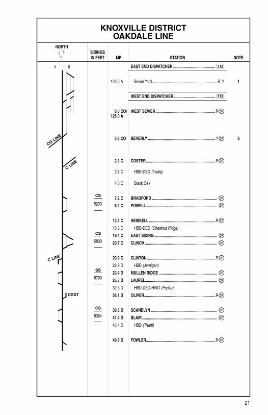
KNOXVILLE DISTRICT OAKDALE LINE
NORTH SIDINGS IN FEET MP STATION NOTE
EAST END DISPATCHER ...........................................
123.0 A Sevier Yard ..................................................................R, Y 1
WEST END DISPATCHER ..........................................
0.0 CO/ WEST SEVIER ............................................................R 125.0 A
3.6 CO BEVERLY .................................................................... Y 3
2.3 C COSTER ......................................................................R
3.8 C HBD-DED (Inskip)
4.6 C Black Oak
7.2 C BRADFORD ..................................................................
8.2 C POWELL ........................................................................
13.4 C HEISKELL ...................................................................R
15.3 C HBD-DED (Chestnut Ridge)
19.4 C EAST SIDING ................................................................
20.7 C CLINCH .........................................................................
20.9 C CLINTON .....................................................................R
22.9 D HBD (Jarnigan)
23.4 D MULLEN RIDGE ...........................................................
25.3 D LAUREL .........................................................................
32.3 D HBD-DED-HWD (Poplar)
36.1 D OLIVER ........................................................................R
39.5 D SCANDLYN ...................................................................
41.4 D BLAIR ............................................................................
45.4 D HBD (Truett)
49.6 D FOWLER ......................................................................R
1 2
CG LINE
C LINE
C LINE
CSXT
5233
5800
8700
9364
CP
772
773
CS
CS
SS
CS
CP
CP
CP
CP
CP
CP
CP
CP
CP
CP
CP
CP
CP
CP

22
KNOXVILLE DISTRICT OAKDALE LINE
NORTH SIDINGS IN FEET MP STATION NOTE
WEST END DISPATCHER ..........................................
50.0 D CANEY CREEK ............................................................. 3
SOUTH END DISPATCHER ........................................
51.3 D HARRIMAN JCT. .......................................................... 2
257.8 SOUTH WATERS ..........................................................
256.5 NORTH WATERS ..........................................................
255.5 TUNNEL 26 ...................................................................
254.8 TUNNEL 25 ...................................................................
254.4 Oakdale
STATION PAGE INFORMATIONNOTE 1: Knoxville Terminal section governs between West End Two Tracks and East Sevier. NOTE 2: Third District section governs between Harriman Jct. and Oakdale. NOTE 3: Knoxville District (KD) Dispatcher controls Coster to Caney Creek, between 8:00AM
and 4:00PM, Monday through Friday.
1. RULES IN EFFECT Main Main 1 Main 2 Track Track TrackBetween Rules East Sevier and West Sevier 261West Sevier and Beverly 261 261 Beverly and Harriman Jct. 261 Harriman Jct. and Tunnel 26 261 261 Tunnel 26 and Tunnel 25 261 Tunnel 25 and Oakdale 261 261
1 2
6200
H LINE
773
CP
102
SS
CP
CP
CP
CP
CP

23
KNOXVILLE DISTRICT OAKDALE LINE
2. MAXIMUM SPEEDS TV Frt.Between MPHMP 123.0 A/0.0 CO, Sevier Yard and MP 51.0 D/258.2, Harriman Jct. 50 50 Except: MP 121.6 A to MP 125.0 A, Old Passenger Main 20 20 MP 0.0 CO to MP 0.6 CO, Curves 20 20 MP 0.6 CO to MP 1.9 CO, Curves 40 40 MP 1.9 CO to MP 3.8 CO, Curves 30 25 MP 3.8 CO, Through Turnout Beverly 25 25 MP 3.8 CO to MP 4.1 CO, Curves 25 25 MP 4.1 CO to MP 7.2 CO, Curves 30 30 MP 6.0 CO to MP 7.2 CO, (Engine only) 20 20 MP 7.2 CO to MP 7.9 CO, Curves 25 25 MP 7.9 CO, Through Turnout Coster 25 25 MP 2.3 C to MP 2.6 C, Curves 25 25 MP 2.6 C to MP 2.8 C, Curves 30 30 MP 2.8 C to MP 4.8 C, Curves 35 35 MP 4.8 C to MP 7.3 C, Curves 45 40 MP 7.3 C to MP 8.2 C, Curves 40 40 MP 8.2 C to MP 10.1 C, Curves 35 35 MP 10.1 C to MP 10.8 C, Curves 20 20 MP 10.8 C to MP 11.3 C, Curves 30 25 MP 11.3 C to MP 20.8 C, Curves 35 35 MP 20.8 C to MP 21.3 C, Curves 15 15 MP 20.8 D to MP 21.1 D, Curves 15 15 MP 20.9 C to MP 21.8 D, Over Street Crossings 25 25 MP 21.1 D to MP 27.8 D, Curves 35 35 MP 23.4 D, Through Turnout Mullen Ridge 20 20 MP 23.4 D to MP 25.3 D, Through Mullen Ridge Siding 20 20 MP 25.3 D, Through Turnout Laurel 20 20 MP 27.8 D to MP 35.7 D, Curves 40 35 MP 35.3 D to MP 35.5 D, Over Street Crossings 35 35 MP 35.7 D to MP 36.2 D, Curves 35 35 MP 36.2 D to MP 43.2 D, Curves 40 40 MP 39.5 D, Through Turnout Scandlyn 20 20 MP 39.5 D to MP 41.4 D, Through Blair Siding 20 20 MP 41.4 D, Through Turnout Blair 20 20 MP 43.2 D to MP 44.9 D, Curves 35 35 MP 44.9 D to MP 48.6 D, Curves 40 40 MP 48.6 D to MP 50.5 D, Curves 35 35 MP 49.6 D to MP 51.2 D (Engines Only) 20 20 MP 50.2 D, Over Street Crossing 25 25 MP 50.5 D to MP 51.5 D, Curves 25 25 MP 51.3 D/258.2, Through Turnout Harriman Jct. 20 20

24
KNOXVILLE DISTRICT OAKDALE LINE
3. CHECKING LOCOMOTIVE SPEED INDICATORTests for accuracy will be made at the following locations and Engineers will adjust speed in accordance with any inaccuracy.
LOCATION OF TEST MILE SIGNS: NORTHWARD SOUTHWARD MP 7.0 C to MP 8.0 C MP 48.0 D to MP 47.0 D MP 45.0 D to MP 44.0 D
NOTE: Tests for accuracy will be made at other locations in addition to those shown. Engineers will choose appropriate locations to check speed indicators.
4. DIESEL UNIT RATINGS DIESEL UNIT RATINGS IN TONS Group 1 Group 2 Group 3 Group 4 Group 5 Group 6
NorthwardSevier to Clinton 1550 2100 2450 3060 3400 4010 Clinton to Blair 1600 2150 2550 3150 3500 4130 Blair to Oakdale 3000 4000 4800 5940 6600 7790
SouthwardOakdale to Blair 1850 2450 2950 3645 4050 4780 Blair to Clinton 1800 2400 2850 3555 3950 4660 Clinton to Powell 1150 1550 1850 2250 2500 2950 Powell to Sevier 1800 2400 2850 3555 3950 4660
5. LOCOMOTIVE AND CAR RESTRICTIONS
A. WEIGHT RESTRICTIONSLoaded 4-axle cars may be handled up to the weight shown provided the stenciled Load Limit (Weight of car and lading) is NOT exceeded. 286,000 lbs.
B. EQUIPMENT RESTRICTIONSTrailing tonnage must be limited on line segments as shown below, behind the following equipment:1. Empty Multi-level cars.2. Empty Intermodal single-platform flats and such loaded with empty trailers or
containers.3. Empty 85-foot-long or longer flats and such flat cars when loaded with empty
trailers or containers, or loaded with only one (1) trailer or container.4. Empty Intermodal single-axle truck flat car or such cars loaded with empty
trailers or containers.5. Empty single or multiple-unit double-stack (well) cars, or articulated single-
platform (spine) cars. Be governed by Appendix 1 in the System Timetable.

25
KNOXVILLE DISTRICT OAKDALE LINE
5. LOCOMOTIVE AND CAR RESTRICTIONS (CONT.)
B. EQUIPMENT RESTRICTIONS (CONT.) Maximum Safe Trailing Tonnage Southward/ Northward/ Line Segments Between Westward EastwardOakdale Line Knoxville and Harriman Jct. See Note 1 3,200NOTE 1: Southward non-radio trains between Heiskell and Powell must not have more than
1,400 tons trailing an empty or part-load long car nor more than 3,500 tons trailing a long car loaded with empty trailers or containers. Trains not in compliance with above restrictions must double or be pushed in accordance with item C below from Heiskell to Powell with the cut being made to ensure that trailing tonnage restrictions are not exceeded.
C. PUSHER SERVICE Between Powell and East Siding: NORTHWARD SOUTHWARD One Conventional 4-Axle (Group 1) No Restriction No Restriction Two Conventional 4-Axle (Group 1) No Restriction No Restriction Three Conventional 4-Axle (Group 1) No Restricted No Restricted Cars Within Cars Within Rear 700 Tons Rear 1000 Tons One High Adhesion 4-Axle (Group 2) No Restriction No Restriction Two High Adhesion 4-Axle (Group 2) No Restricted No Restricted Cars Within Cars Within Rear 1100 Tons Rear 1200 Tons One Conventional 6-Axle (Group 3) No Restriction No Restriction Two Conventional 6-Axle (Group 3) No Restricted No Restricted Cars Within Cars Within Rear 1100 Tons Rear 1200 Tons One High Adhesion 6-Axle (Group 5) No Restriction No Restriction 1. Amperage on Pusher unit(s) must be limited to a safe level when speed of train being pushed
falls below 9 MPH or when starting train fully on grade. 2. Above restrictions apply to radio-controlled (midtrain) units on radio control trains being
pushed. 3. No other combination of units other than those listed above may be used in Pusher Service
over above territory. EXCEPT: The equivalent of 24 conventional axles may be used in pusher service where train being pushed is a Solid Loaded Bulk Commodity train.
4. A “restricted car” is an empty auto multi-level car, empty intermodal single platform flat or such cars loaded with empty trailers or containers, empty 85-foot long or longer flat cars or such cars when loaded with empty trailers or containers, or loaded with only one (1) trailer or con-tainer, or empty intermodal single-axle-truck flat cars or such cars loaded with empty trailers or containers.

26
KNOXVILLE DISTRICT OAKDALE LINE
6. SWITCHES AND DERAILS
A. SWITCHESMain Track switches not equipped with electric locks: MP 3.9 CO — TVA Track, Beverly MP 6.7 CO — Kelso Oil Track MP 7.2 CO — K&O Belt Wye MP 2.4 C — Tassco MP 3.8 C — Enco Steel MP 17.5 C — Peak MP 27.1 D — Dossett These switches must not at any time be used to clear the Main Line at any of these tracks. While using these tracks, an engine or car must continuously occupy the Main Track or the Main Track switch must be kept continuously set for movement into such track.
B. JUNCTIONS INTERLOCKED
Milepost Location Line/R.R. 0.0 CO West Sevier A Line 3.6 CO Beverly CG Line 2.3 C/7.9 CO Coster C Line 20.9 C Clinton D Line 36.1 D Oliver CSXT 51.3 D Harriman Jct. CNO&TP Line
7. COMMUNICATION INFORMATION Channel 1 Channel 2 Base Station TX and RX TX (RX)West Sevier 56 NASharps Ridge 56 48 (9)Heiskell 56 NAClinton 56 NAPoplar 56 NA
8. DETECTOR INSTRUCTIONSNone.
27
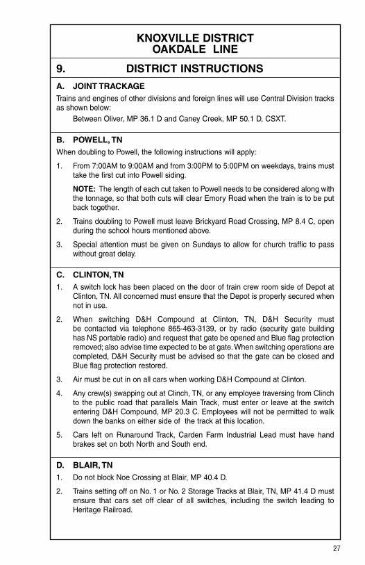
KNOXVILLE DISTRICT OAKDALE LINE
9. DISTRICT INSTRUCTIONS
A. JOINT TRACKAGETrains and engines of other divisions and foreign lines will use Central Division tracks as shown below: Between Oliver, MP 36.1 D and Caney Creek, MP 50.1 D, CSXT.
B. POWELL, TN When doubling to Powell, the following instructions will apply:
1. From 7:00AM to 9:00AM and from 3:00PM to 5:00PM on weekdays, trains must take the first cut into Powell siding.
NOTE: The length of each cut taken to Powell needs to be considered along with the tonnage, so that both cuts will clear Emory Road when the train is to be put back together.
2. Trains doubling to Powell must leave Brickyard Road Crossing, MP 8.4 C, open during the school hours mentioned above.
3. Special attention must be given on Sundays to allow for church traffic to pass without great delay.
C. CLINTON, TN 1. A switch lock has been placed on the door of train crew room side of Depot at
Clinton, TN. All concerned must ensure that the Depot is properly secured when not in use.
2. When switching D&H Compound at Clinton, TN, D&H Security must be contacted via telephone 865-463-3139, or by radio (security gate building has NS portable radio) and request that gate be opened and Blue flag protection removed; also advise time expected to be at gate. When switching operations are completed, D&H Security must be advised so that the gate can be closed and Blue flag protection restored.
3. Air must be cut in on all cars when working D&H Compound at Clinton.
4. Any crew(s) swapping out at Clinch, TN, or any employee traversing from Clinch to the public road that parallels Main Track, must enter or leave at the switch entering D&H Compound, MP 20.3 C. Employees will not be permitted to walk down the banks on either side of the track at this location.
5. Cars left on Runaround Track, Carden Farm Industrial Lead must have hand brakes set on both North and South end.
D. BLAIR, TN 1. Do not block Noe Crossing at Blair, MP 40.4 D.
2. Trains setting off on No. 1 or No. 2 Storage Tracks at Blair, TN, MP 41.4 D must ensure that cars set off clear of all switches, including the switch leading to Heritage Railroad.

28
KNOXVILLE DISTRICT OAKDALE LINE
9. DISTRICT INSTRUCTIONS (CONT.)
E. END-OF-TRAIN DEVICE — GRADESReference the identification of grades as required in NS-1 Rules for Equipment Operation and Handling, Rule A-31, End-Of-Train Device and revised NS-1 Rule L-241, to include instructions for descending grades of 1% or more.
In accordance with CFR Part 232, the following designated sections of track are identi-fied as average grades of:
2% or greater over a distance of 2 continuous miles or 1% or greater over a distance of 3 continuous miles:
KNOXVILLE DISTRICT Oakdale Line
Northward Southward MP 9.8 C to MP 12.8 C = 1.42% MP 4.0 C to MP 1.0 C = 1.02% MP 15.2 C to MP 12.8 C = 1.33%

29
KNOXVILLE DISTRICT JELLICO LINE
NORTH SIDINGS IN FEET MP STATION NOTE
WEST END DISPATCHER .......................................... 2
20.9 C CLINTON .....................................................................R
30.4 C Lake City ......................................................................... R
38.4 C Caryville
47.0 C Buckeye
49.0 C Pioneer ........................................................................... R
55.1 C Elk Valley
62.0 C Newcomb
66.0 C Jellico ............................................................................. R
CSXT DISPATCHER 1, 3
67.6 C LOT ................................................................................
72.0 C HOLTON ........................................................................
76.0 C Arco Jct. ......................................................................... R
79.1 C Clairfield
85.0 C Fonde
STATION PAGE INFORMATIONNOTE 1: CSXT Timetable and Rules govern between Lot and MP 74.0 C. NOTE 2: Knoxville District (KD) Dispatcher controls Clinton to Lot, 8:00AM to 4:00PM,
Monday through Friday. NOTE 3: CSXT Dispatcher tone-in Channel 14-14 — Tone 6.
1. RULES IN EFFECT Main TrackBetween RulesClinton and Lot 171
C LINE D LINE CP
773
CP
CP

30
KNOXVILLE DISTRICT JELLICO LINE
2. MAXIMUM SPEEDS Main TrackBetween MPHMP 20.9 C, Clinton and MP 46.0 C 30 Except: MP 20.8 C to MP 21.1 C, Curves 15 MP 24.4 C to MP 24.9 C, Curves 25MP 46.0 C and MP 65.0 C, Jellico 25 Except: MP 49.0 C to MP 51.4 C, Curves and Tunnels 15 MP 59.7 C to MP 59.9 C, Curve and Tunnel 15 MP 65.0 C, Jellico to MP 67.7 C, Lot 20 MP 67.3 C to MP 67.4 C, Over Bridge 10 MP 72.0 C, Holton to MP 84.7 C, Fonde 10Auxiliary Tracks: Straight Creek Industrial Lead (Kopper Glo Mine Spur) 5South End Turley Industry Track, Over Switch-Point Derail, MP 44.3 C 5
3. CHECKING LOCOMOTIVE SPEED INDICATORTests for accuracy will be made at the following locations and Engineers will adjust speed in accordance with any inaccuracy.
LOCATION OF TEST MILE SIGNS: NORTHWARD SOUTHWARD MP 26.0 C to MP 27.0 C MP 63.0 C to MP 62.0 C MP 33.0 C to MP 34.0 C
NOTE: Tests for accuracy will be made at other locations in addition to those shown. Engineers will choose appropriate locations to check speed indicators.
4. DIESEL UNIT RATINGS DIESEL UNIT RATINGS IN TONS Group 1 Group 2 Group 3 Group 4 Group 5 Group 6
NorthwardClinton to Lake City 3000 4000 4800 5940 6600 7790 Lake City to Lot 1500 2000 2400 2970 3300 3890
SouthwardLot to Pioneer 1450 1950 2300 2880 3200 3780 Pioneer to Lake City 2300 3050 3650 4545 5050 5960 Lake City to Clinton 4700 6250 7500 9315 10350 12210

31
KNOXVILLE DISTRICT JELLICO LINE
5. LOCOMOTIVE AND CAR RESTRICTIONS
A. WEIGHT RESTRICTIONSLoaded 4-axle cars may be handled up to the weight shown provided the stenciled Load Limit (Weight of car and lading) is NOT exceeded. 286,000 lbs.
B. EQUIPMENT RESTRICTIONSTrailing tonnage must be limited on line segments as shown below, behind the following equipment:1. Empty Multi-level cars.2. Empty Intermodal single-platform flats and such loaded with empty trailers or
containers.3. Empty 85-foot-long or longer flats and such flat cars when loaded with empty
trailers or containers, or loaded with only one (1) trailer or container.4. Empty Intermodal single-axle truck flat car or such cars loaded with empty
trailers or containers.5. Empty single or multiple-unit double-stack (well) cars, or articulated single-
platform (spine) cars. Be governed by Appendix 1 in the System Timetable.
Maximum Safe Trailing Tonnage Southward/ Northward/ Line Segments Between Westward EastwardJellico Line Clinton and Fonde Unrestricted Unrestricted
6. SWITCHES AND DERAILS
JUNCTIONS NON-INTERLOCKED
Milepost Location Line/R.R. 67.6 C Lot CSXT
INTERLOCKED Milepost Location Line/R.R. 20.9 C Clinton D Line
7. COMMUNICATION INFORMATION Channel 1 Channel 2 Base Station TX and RX TX (RX)Clinton 56 NALake City 56 NAPioneer 56 NAJellico 56 NAArco 56 NA
8. DETECTOR INSTRUCTIONSNone.

32
KNOXVILLE DISTRICT JELLICO LINE
9. DISTRICT INSTRUCTIONS
A. EXCESSIVE CURVATURE Listed below are tracks with curvature of 12 degrees, 30 minutes or greater:
Milepost Location Curvature 21.6 C Eagle Bend-Carlisle Tire 12.8 degrees 21.6 C Eagle Bend-Techmere 15.8 degrees 21.6 C Eagle Bend-Food Lion 15.0 degrees Refer to the Equipment Restriction Section of the System Timetable.
B. JOINT TRACKAGE1. Trains and engines of the Central Division will use tracks of other divisions and
foreign lines in accordance with their Timetables, Rules, and Regulations as shown below:
Between Lot, MP 67.6 C and MP 74.0 C, CSXT.
2. Trains and engines of other divisions and foreign lines will use Central Division tracks as shown below:
Between MP 74.0 C and Fonde, MP 85.0 C, CSXT.
C. CLAIRFIELD (Kopper-Glo Mine Spur) On descending grade between Kopper-Glo Mine Spur and Clairfield, TN, MP 79.1 C, trains switching, doubling tracks and/or departing will be governed by the following instructions:1. All air hoses must be coupled, all angle cocks properly positioned and hand
brakes must remain applied. Prior to attempting to move, brake pipe pressure must be charged to 90 PSI for a minimum of 15 minutes. After brake system is charged, a 20 PSI brake pipe service reduction must be made, and crew will inspect brakes on each car. Hand brakes must be set on car(s) which brake fails to apply. When the inspection is completed, Engineer will release the automatic brake and will not attempt to move until brake pipe pressure has been recharged to 90 PSI for five (5) minutes. After brake system is charged, Engineer will make a 15 PSI brake pipe reduction and allow exhaust to cease. Handbrakes may then be released (except on cars with inoperative air brakes).
2. Train may then be started, pulling away if necessary. As cars balance on grade, dynamic brake when available, must be used in conjunction with train air brake to control movement at a speed not to exceed 5 MPH.
3. Air brake must not be released while movement is on the major descending grade between main crossing at Kopper Glo tipple and first trestle west of this crossing, unless movement is stopped and minimum of 50% hand brakes are applied.
4. Switches located on Straight Creek Industrial Lead (Kopper-Glo Mine Spur), MP 78.9 C, can be left as last used. Trains or engines can expect to find switches lined and locked as last used when operating on this lead.
5. Engines must not operate under tipple and structure back of tipple at Straight Creek Spur, Kopper Glo Mine, MP 79.0 C.

33
KNOXVILLE DISTRICT JELLICO LINE
9. DISTRICT INSTRUCTIONS (CONT.)
D. LOT AND HOLTON Trains stopped at Lot, MP 67.6 C or Holton, MP 72.0 C for CSXT STOP signal and after a ten-minute period are unable to contact the CSXT KD Dispatcher in Jacksonville, FL, via radio, must use the telephone at these locations.
E. LAKE CITY 1. Close clearance exists in all tracks in Lake City Yard. 2. Beech Grove Branch at Lake City is out of service.
F. MP 46.1 C — ROYAL BLUE The two derails, located on the west end of Industry Lead and Runaround Track must be left in the off position except when equipment is tied down on these tracks.
NOTE: The switch point derail located on the east end of Industry Lead must be lined and locked in derailing position after use.
G. END-OF-TRAIN DEVICE — GRADESReference the identification of grades as required in NS-1 Rules for Equipment Operation and Handling, Rule A-31, End-Of-Train Device and revised NS-1 Rule L-241, to include instructions for descending grades of 1% or more.
In accordance with CFR Part 232, the following designated sections of track are identi-fied as average grades of:
2% or greater over a distance of 2 continuous miles or 1% or greater over a distance of 3 continuous miles:
KNOXVILLE DISTRICT Jellico Line
Northward Southward MP 49.0 C to MP 55.0 C = 1.22% MP 37.0 C to MP 32.0 C = 1.03%
H. BRICEVILLE BRANCH, MP 0.0 CA TO MP 1.2 CA — EXCEPTED TRACK
Per 49 CFR (Code of Federal Regulations), Part 213 — Track Safety Standards, Subpart A — General Section 213.4 entitled Excepted Track, Briceville Branch, MP 0.0 CA to MP 1.2 CA, Wye Switch to McCall Mine, is hereby designated as an “EXCEPTED TRACK”. The track on bridges and bridge approaches (100 feet each side of a bridge) and the track within the limits of public streets or highways is EXCLUDED from the “EXCEPTED TRACK”.
No occupied passenger trains may operate on this line segment.
No freight trains may operate with more than five (5) cars required to be placarded by the Hazardous Materials Regulations (49 CFR, Part 172).
Briceville Branch from MP 0.0 CA to MP 1.2 CA is out of service. Switch is spiked and tagged.

34
KNOXVILLE DISTRICT JELLICO LINE
9. DISTRICT INSTRUCTIONS (CONT.)
I. 6-AXLE AC LOCOMOTIVES 6-axle AC locomotives, regardless of weight CANNOT be handled on the following segment: Jellico Line, MP 72.5 C to MP 79.4 C
J. 6-AXLE WRECKERS AND LOCOMOTIVE CRANES 4- and 6-axle Wreckers and Locomotive Cranes must not exceed 10 MPH between Hyde and Fonde.
K. MAIN TRACK, MP 79.5 C AND FONDE, MP 85.0 CThe Main Track between MP 79.5 C and Fonde, MP 85.0 C is out of service and cannot be used.

35
KNOXVILLE DISTRICT BRISTOL LINE
WEST SIDINGS IN FEET MP STATION NOTE
VIRGINIA DIVISION DISPATCHER ............................
NB 406.3 BRISTOL .................................................................. r, Y 2
EAST END DISPATCHER ...........................................
0.3 A FORD .............................................................................
11.0 A Bluff City ......................................................................... R
12.4 A HBD-DED (Bluff City)
13.7 A CURTIS ........................................................................R
15.7 A PINEY FLATS ................................................................
24.8 A Johnson City ................................................................... R
27.2 A HBD-DED (Johnson City)
33.0 A Jonesborough
35.9 A SAND VALLEY ............................................................R
37.9 A TELFORD ....................................................................R
40.3 A HBD-DED (Telford)
50.5 A Afton
52.9 A HBD-DED (Afton)
56.7 A Greeneville ...................................................................... R
62.3 A JONES ...........................................................................
64.4 A RADER ..........................................................................
66.8 A HBD-DED (Mosheim)
71.4 A MOHAWK
75.7 A Bulls Gap ....................................................................R, Y 3
76.0 A JUSTICE ........................................................................
77.6 A KITE ...............................................................................
79.0 A HBD-DED (Whitesburg)
82.6 A Russellville
87.1 A HBD-DED (Morristown)
89.0 A PICKENS .......................................................................
11000
9629
9799
10114
4614
5925
9895
TC LINE
2 1
CP
552
SS
CP
CP
CP
SS
SS
SS
SS
CP
CP
CP
CP
CP
CP
CP
772

36
KNOXVILLE DISTRICT BRISTOL LINE
WEST SIDINGS IN FEET MP STATION NOTE
EAST END DISPATCHER ...........................................
91.4 A NEW LINE .....................................................................
92.4 A Morristown
92.7 A COULTER ......................................................................
94.1 A ALPHA ...........................................................................
98.9 A HBD-DED-HWD (Talbott)
100.0 A KEISTER .....................................................................R
107.1 A FRIENDS .......................................................................
110.2 A HODGES .......................................................................
111.2 A HBD-DED (Hodges)
117.7 A DED (Mascot) 4
119.2 A ROSEBERRY ................................................................
121.6 A EAST SEVIER ...............................................................
122.2 A LIZZIE ............................................................................
123.0 A Sevier Yard ...................................................................... Y
WEST END DISPATCHER .......................................... 1
125.0 A WEST SEVIER ............................................................R
STATION PAGE INFORMATIONNOTE 1: Knoxville Terminal section governs between East Sevier and West End Two Tracks. NOTE 2: Virginia Division Timetable governs between Ford and Bristol. NOTE 3: Knoxville (KD) Dispatcher handles between Bulls Gap and Ford, 8:00AM to 4:00PM,
Monday through Friday. NOTE 4: Voice alarm only.
2 1
S LINE
CP
772
CP
CP
CP
CP
CP
CP
CP
CP
773
CP

37
KNOXVILLE DISTRICT BRISTOL LINE
1. RULES IN EFFECT Main Main 1 Main 2 Track Track TrackBetween Rules Bristol and Piney Flats 261Piney Flats and Sand Valley 271Sand Valley and Telford 261Telford and Jones 271Jones and Rader 261Rader and Justice 271Justice and Pickens 261Pickens and Alpha 261 261Alpha and Keister 261Keister and Hodges 261 261Hodges and Roseberry 261Roseberry and East Sevier 261 261East Sevier and West Sevier 261

38
KNOXVILLE DISTRICT BRISTOL LINE
2. MAXIMUM SPEEDS TV Frt.Between MPHMP NB 406.3, Bristol and MP 125.0 A, West Sevier 60 50 Except: MP NB 406.3, Bristol to MP 0.3 A, Ford 20 20 MP NB 406.3, Through Turnout Bristol 20 20 MP NB 406.3 to MP 0.3 A, Through Siding Bristol 20 20 MP 0.0 A to MP 0.2 A, Curves 25 25 MP 0.2 A to MP 2.2 A, Curves 30 30 MP 3.3 A, Through Turnout Ford 20 20 MP 2.2 A to MP 3.2 A, Curves 35 35 MP 3.2 A to MP 6.9 A, Curves 40 35 MP 6.9 A to MP 15.7 A, Curves 35 35 MP 13.7 A, Through Turnout Curtis 25 25 MP 13.7 A to MP 15.7 A, Through Siding Piney Flats 25 25 MP 15.7 A, Through Turnout Piney Flats 25 25 MP 15.7 A to MP 16.0 A, Curves 40 40 MP 16.0 A to MP 18.7 A, Curves 35 35 MP 18.7 A to MP 22.0 A, Curves 40 35 MP 22.0 A to MP 30.0 A, Over Street Crossings 35 35 MP 22.0 A to MP 24.8 A, Curves 50 45 MP 24.8 A to MP 25.3 A, Curves 40 35 MP 25.3 A to MP 28.4 A, Curves 45 40 MP 28.4 A to MP 31.8 A, Curves 35 35 MP 31.8 A to MP 32.8 A, Curves 25 25 MP 32.8 A to MP 33.1 A, Curves 35 35 MP 33.1 A to MP 34.5 A, Curves 45 45 MP 34.5 A to MP 34.9 A, Curves 40 45 MP 34.9 A to MP 38.3 A, Curves 50 45 MP 35.9 A, Through Turnout Sand Valley 25 25 MP 35.9 A to MP 37.9 A, Through Siding Telford 25 25 MP 37.9 A, Through Turnout Telford 25 25 MP 38.3 A to MP 38.7 A, Curves 40 35 MP 38.7 A to MP 39.6 A, Curves 45 40 MP 39.6 A to MP 42.2 A, Curves 50 45 MP 42.2 A to MP 42.7 A, Curves 40 40 MP 42.7 A to MP 43.7 A, Curves 35 35 MP 43.7 A to MP 44.5 A, Curves 45 45 MP 44.5 A to MP 44.9 A, Curves 40 40 MP 44.9 A to MP 47.8 A, Curves 45 45 MP 47.8 A to MP 48.2 A, Curves 40 35 MP 48.2 A to MP 51.6 A, Curves 45 45 MP 49.5 A to MP 50.6 A, Through Siding Afton 10 10 MP 51.6 A to MP 51.9 A, Curves 35 35 MP 51.9 A to MP 53.3 A, Curves 40 40 MP 53.3 A to MP 54.9 A, Curves 45 45 MP 54.9 A to MP 56.7 A, Curves 40 40 MP 56.7 A to MP 58.2 A, Curves 45 45 MP 58.2 A to MP 58.7 A, Curves 45 40 MP 58.7 A to MP 59.6 A, Curves 45 45 MP 59.6 A to MP 60.1 A, Curves 40 35 MP 60.1 A to MP 60.4 A, Curves 35 35 MP 60.4 A to MP 61.4 A, Curves 45 45

39
KNOXVILLE DISTRICT BRISTOL LINE
2. MAXIMUM SPEEDS (CONT.) TV Frt.Between MPH MP 61.4 A to MP 61.8 A, Curves 40 35 MP 61.8 A to MP 64.8 A, Curves 50 50 MP 62.3 A, Through Turnout Jones 25 25 MP 62.3 A to MP 64.4 A, Through Siding Rader 25 25 MP 64.4 A, Through Turnout Rader 25 25 MP 64.8 A to MP 65.2 A, Curves 45 40 MP 65.2 A to MP 65.5 A, Curves 40 35 MP 65.5 A to MP 65.9 A, Curves 45 40 MP 65.9 A to MP 67.8 A, Curves 45 45 MP 67.8 A to MP 68.2 A, Curves 40 40 MP 68.2 A to MP 74.2 A, Curves 45 45 MP 74.2 A to MP 76.8 A, Curves 40 40 MP 76.8 A to MP 77.0 A, Curves 40 35 MP 77.0 A to MP 77.5 A, Curves 40 40 MP 77.5 A to MP 79.8 A, Curves 45 45 MP 79.8 A to MP 79.9 A, Curves 45 40 MP 79.9 A to MP 80.6 A, Curves 40 40 MP 80.6 A to MP 82.3 A, Curves 50 50 MP 81.5 A to MP 82.6 A, Through Siding Russellville 10 10 MP 82.3 A to MP 83.5 A, Curves 50 45 MP 83.5 A to MP 84.9 A, Curves 45 40 MP 84.9 A to MP 85.2 A, Curves 40 35 MP 85.2 A to MP 88.8 A, Curves 45 40 MP 88.2 A to MP 89.5 A, Over Street Crossings 25 25 MP 88.8 A to MP 91.6 A, Curves 40 40 MP 89.0 A, Through Turnout Pickens 40 40 MP 91.4 A, Through Turnout New Line 40 40 MP 91.4 A, Through Crossover New Line 25 25 MP 91.6 A to MP 92.2 A, Curves 55 50 MP 92.2 A to MP 101.1 A, Curves 60 50 MP 94.1 A, Through Turnout Alpha 40 40 MP 100.0 A, Through Turnout Keister 40 40 MP 101.1 A to MP 101.3 A, Curves 55 50 MP 101.3 A to MP 101.4 A, Curves 40 40 MP 101.4 A to MP 101.9 A, Curves 40 35 MP 101.6 A to MP 102.3 A, Over Street Crossings 40 40 MP 101.9 A to MP 102.6 A, Curves 40 40 MP 102.6 A to MP 105.4 A, Curves 50 50 MP 105.4 A to MP 107.6 A, Curves 60 50 MP 107.1 A, Through Turnout Friends 40 40 MP 107.6 A to MP 107.9 A, Curves 50 50 MP 107.9 A to MP 108.8 A, Curves 55 50 MP 108.8 A to MP 114.1 A, Curves 60 50 MP 110.2 A, Through Turnout Hodges 40 40 MP 114.1 A to MP 116.8 A, Curves 45 40 MP 116.8 A to MP 119.0 A, Curves 45 40 MP 119.0 A to MP 119.2 A, Curves 40 40 MP 119.2 A, Through Turnout Roseberry 40 40 MP 119.2 A to MP 120.1 A, Curves 45 40 MP 120.1 A to MP 121.7 A, Curves 35 35 MP 121.6 A, Through Turnout East Sevier 25 25 MP 121.6 A to MP 125.0 A, Old Passenger Main 20 20

40
KNOXVILLE DISTRICT BRISTOL LINE
3. CHECKING LOCOMOTIVE SPEED INDICATORTests for accuracy will be made at the following locations and Engineers will adjust speed in accordance with any inaccuracy.
LOCATION OF TEST MILE SIGNS: WESTWARD EASTWARD MP 5.0 A to MP 6.0 A MP 113.0 A to MP 112.0 A MP 71.0 A to MP 72.0 A MP 112.0 A to MP 111.0 A MP 73.0 A to MP 74.0 A MP 79.0 A to MP 78.0 A
NOTE: Tests for accuracy will be made at other locations in addition to those shown. Engineers will choose appropriate locations to check speed indicators.
4. DIESEL UNIT RATINGS DIESEL UNIT RATINGS IN TONS Group 1 Group 2 Group 3 Group 4 Group 5 Group 6
WestwardBristol to Carnegie 1500 2000 2400 2970 3300 3890 Carnegie to Bulls Gap 1700 2250 2700 3375 3750 4430 Bulls Gap to Morristown 2050 2750 3250 4050 4500 5310 Morristown to Mascot 2550 3400 4050 5040 5600 6610 Mascot to Sevier 3550 4750 5650 7020 7800 9200
EastwardSevier Yd to New Line 2150 2850 3450 4230 4700 5550 New Line to Bulls Gap 2600 3450 4150 5130 5700 6730 Bulls Gap to Greeneville 1500 2000 2400 2970 3300 3840 Greeneville to Carnegie 1800 2400 2850 3550 3950 4660 Carnegie to Bristol 1600 2150 2550 3150 3500 4130
5. LOCOMOTIVE AND CAR RESTRICTIONS
A. WEIGHT RESTRICTIONSLoaded 4-axle cars may be handled up to the weight shown provided the stenciled Load Limit (Weight of car and lading) is NOT exceeded. 286,000 lbs.

41
KNOXVILLE DISTRICT BRISTOL LINE
5. LOCOMOTIVE AND CAR RESTRICTIONS (CONT.)
B. EQUIPMENT RESTRICTIONSTrailing tonnage must be limited on line segments as shown below, behind the following equipment:1. Empty Multi-level cars.2. Empty Intermodal single-platform flats and such loaded with empty trailers or
containers.3. Empty 85-foot-long or longer flats and such flat cars when loaded with empty
trailers or containers, or loaded with only one (1) trailer or container.4. Empty Intermodal single-axle truck flat car or such cars loaded with empty
trailers or containers.5. Empty single or multiple-unit double-stack (well) cars, or articulated single-
platform (spine) cars. Be governed by Appendix 1 in the System Timetable.
Maximum Safe Trailing Tonnage Southward/ Northward/ Line Segments Between Westward EastwardBristol Line Bristol and Sevier Yard 6,000 7,400
6. SWITCHES AND DERAILS
A. SWITCHES Main Track switches not equipped with electric locks: MP 2.7 A — Marley Mouldings MP 3.4 A — Universal Siding MP 12.3 A — 84 Lumber Co. MP 14.4 A — TVA MP 15.0 A — Amerace MP 84.6 A — AmeriGas MP 93.9 A — Colgate
Main Track switches not equipped with electric locks must not at any time be used to clear Main Line. No trains or engines shall clear the Main Line at any of these tracks. While using such tracks, an engine or car must continuously occupy the Main Track or main switch must be continuously set for movement into such track.
B. SPRING SWITCHES Spring switches are located as follows:Milepost Location Normal Position 75.6 A East End, Bulls Gap Siding Main Track
C. JUNCTIONS INTERLOCKED
Milepost Location Line/R.R. 91.4 A New Line S Line76.0 A Justice TC Line
NON-INTERLOCKEDMilepost Location Line/R.R. 25.3 A Johnson City ETRY

42
KNOXVILLE DISTRICT BRISTOL LINE
7. COMMUNICATION INFORMATION Channel 1 Channel 2 Base Station TX and RX TX (RX)Jefferson City 56 48 (9)Bulls Gap 56 NAGreeneville 56 NABuffalo Mountain 56 48 (9)Bluff City 56 NA
8. DETECTOR INSTRUCTIONSNone.
9. DISTRICT INSTRUCTIONS
A. EXCESSIVE CURVATUREListed below are tracks with curvature of 12 degrees, 30 minutes or greater: Milepost Location Curvature 15.0 A Amerace 19.5 degrees 29.1 A Elizabethton Herb and Metal 19.0 degrees 50.0 A Plus Mark 16.0 degrees 51.0 A Jarden Zinc 14.0 degrees 53.9 A Southern Packing Company 21.0 degrees 54.5 A Pig Track 14.5 degrees55.5 A Johnson City Chemical 17.5 degrees 89.2 A International Forest Products 15.5 degrees 90.5 A New Farmers Warehouse (Track 1) 19.0 degrees 95.2 A Rich Allen 14.0 degrees 100.5 A Jeff City Cabinet (Track 2) 14.0 degrees 109.9 A Young Mine (Track 1) 15.0 degrees Refer to the Equipment Restriction Section of the System Timetable.
B. JOINT TRACKAGE1. Trains and engines of the Central Division will use tracks of other divisions and
foreign lines in accordance with their Timetables, Rules, and Regulations as shown below:
Between: Ford, MP 0.3 A and Bristol, MP NB 406.3, VA Division
2. Trains and engines of other divisions and foreign lines will use Central Division tracks as shown below:
Between: Bristol, MP 0.0 A and MP 4.0 A, VA Division Carnegie Yard, MP 23.0 A and MP 24.0 A, ETRY
C. JOINT TRACK AUTHORITY IS REQUIRED AT THE FOLLOWING LOCATIONS:
Between Bristol, MP NB 406.3 and Ford, MP 0.3 A East End Dispatcher and VA Division Dispatcher at Roanoke

43
KNOXVILLE DISTRICT BRISTOL LINE
9. DISTRICT INSTRUCTIONS (CONT.)
D. RAILROAD CROSSING AT GRADEINTERLOCKED
Milepost Location Line/R.R. 24.0 A Carnegie ETRY
E. MARLEY MOULDINGS, MP 2.7 AThe final 252 feet of this track is level and this level section of track is the only location where cars are to be left standing between the double switch-point derail and the level section of track account the severe grade of 2.5%. 100% hand brakes are required on all cars left standing on the Marley Moundings Track.
F. JOHNSON CITY 1. Proper precaution must be exercised while riding shove moves in Carnegie Yard
due to close clearances between yard tracks.
2. Road crossings within the city limits of Johnson City will not be blocked in excess of 10 minutes.
G. GREENEVILLE 1. When spotting cars at Cherokee Lumber, MP 65.6 A do not spot any cars east
of Spring Street.
2. Employees are prohibited from riding on the side of equipment adjacent to Storage Tracks at Minco, MP 67.5 A.
H. BULLS GAP 1. Trains having TOFC and/or COFC cars in their consist will not be shoved around
the east leg of the Wye at Bulls Gap without first receiving permission from a Division Officer.
2. Shepard Road, MP 86.6 TC must not be blocked except when switching.
3. Do not block Bible Crossing and first crossing west of Bible Crossing at MP 77.1 A in excess of 10 minutes. Any time crossing will be blocked longer, arrangements must be made to cut crossing.
I. WHITESBURG Westward trains being assisted (shoved) over Whitesburg Hill, MP 80.5 A must not stop to detach pusher prior to the head end reaching the west end of Russellville Siding, MP 82.5 A.
J. PICKENS When eastward trains stop at Pickens to meet a westward train or to be passed by another eastward train, the stopped train MUST NOT ACTIVATE THE AUTOMATIC GRADE CROSSING PROTECTION at S. Fairmount Avenue (“Chicken House” crossing), MP 89.7 A.

44
KNOXVILLE DISTRICT BRISTOL LINE
9. DISTRICT INSTRUCTIONS (CONT.)
K. MORRISTOWN 1. Except in an emergency, Austin Drive, MP 91.1 A (Woodcrafter’s Crossing) is
not to be blocked in excess of five (5) minutes. If necessary, crews will cut the crossing.
2. Account grade in excess of 1.5%, locomotives that are to be left unattended on the New Farmers Warehouse Track, MP 90.2 A, are to be left running to supply air for the airbrakes.
L. FRIENDS Eastward trains to be held at Friends for more than 15 minutes must stop short of Watercress Crossing, MP 107.4 A.
M. MASCOT Do not block Mascot Pike Road crossing, MP 117.1 A, in excess of 10 minutes.
N. END-OF-TRAIN DEVICE — GRADESReference the identification of grades as required in NS-1 Rules for Equipment Operation and Handling, Rule A-31, End-Of-Train Device and revised NS-1 Rule L-241, to include instructions for descending grades of 1% or more.
In accordance with CFR Part 232, the following designated sections of track are identi-fied as average grades of:
2% or greater over a distance of 2 continuous miles or 1% or greater over a distance of 3 continuous miles:
KNOXVILLE DISTRICT Bristol Line
Eastward Westward MP 53.3 A to MP 49.8 A = 1.00% MP 7.8 A to MP 10.8 A = 1.10% MP 80.5 A to MP 77.7 A = 1.00% MP 58.0 A to MP 62.5 A = 1.31% MP 66.4 A to MP 70.0 A = 1.13% MP 103.3 A to MP 107.0 A = 1.00%

45
KNOXVILLE DISTRICT WEST END
WEST SIDINGS IN FEET MP STATION NOTE
WEST END DISPATCHER ..........................................
125.0 A WEST SEVIER ............................................................R
130.7 A KNOXVILLE .................................................................... Y
131.2 A K&A JCT.
132.2 A WEST END TWO TRACKS .............................................
135.4 A Bearden
136.9 A HBD-DED (Bearden)
139.3 A Ebenezer
145.1 A HBD-DED (Concord)
146.5 A Boyd
154.0 A Lenoir City ...................................................................... R
154.8 A HBD-DED (Lenoir City)
159.6 A Loudon ............................................................................ Y
161.3 A Craig
165.5 A Philadelphia
169.2 A HBD-DED-HWD (Sweetwater)
172.0 A Sweetwater
172.2 A Sweetwater Sdg.
179.2 A HBD-DED (Niota)
179.8 A Niota
183.7 A Hutsell
185.9 A Athens ............................................................................ R
188.2 A HBD-DED (Coile)
189.3 A Coile
195.4 A DED (Sanford) 3
195.6 A Sanford
198.4 A HBD-DED (Calhoun)
200.9 A Charleston
206.7 A Tasso
209.8 A HBD-DED (Tasso)
2
7714
2000
10688
3885
6994
10400
7307
7720
7341
1 2
K&A LINE
1
CP
773

46
KNOXVILLE DISTRICT WEST END
WEST SIDINGS IN FEET MP STATION NOTE
WEST END DISPATCHER ..........................................
211.7 A LYLE ..............................................................................
212.7 A Cleveland ........................................................................ R
213.5 A BRADLEY .................................................................... Y
215.0 A DOCKERY .....................................................................
219.3 A HBD-DED (McDonald)
220.8 A McDonald
GEORGIA DIVISION DISPATCHER ........................... 1
225.2 A SLIDE 4
226.6 A OOLTEWAH .................................................................R
230.5 A SUMMIT .........................................................................
232.3 A HBD-DED (Tyner)
CT DISPATCHER ........................................................ 2
235.0 A JERSEY .........................................................................
236.0 A WILLIAMS .....................................................................
236.6 A SPELL ...........................................................................
237.3 A BROWN ....................................................................... Y
238.2 A CITICO JCT. ................................................................ Y
238.7 A PIERCE ..........................................................................
234.8 A WEBB ............................................................................
240.0.A Debutts Yard ................................................................... Y
STATION PAGE INFORMATIONNOTE 1: Georgia Division Timetable governs between Ooltewah and Jersey. NOTE 2: Chattanooga Terminal section governs between Tenbridge and Wauhatchie. NOTE 3: Voice alarm only.NOTE 4: Slide Detector only. Alarm located in Train Dispatcher’s office.
9050
7122I LINE
H LINE
CNO&TP LINE
2 1
CP
773
CS
CP
CP
CP
CP
CP
CP
CP
CP
CP
CP
CP
442
774

47
KNOXVILLE DISTRICT WEST END
1. RULES IN EFFECT Main Main 1 Main 2 Track Track TrackBetween Rules West Sevier and West End Two Tracks 251 251West End Two Tracks and Lyle 271Lyle and Ooltewah 261Ooltewah and Jersey 261 261Jersey and Pierce 261 261Pierce and DeButts Yard 261
2. MAXIMUM SPEEDS TV Frt.Between MPHMP 123.0 A, Sevier Yard and MP 240.0 A, DeButts Yard 60 50 Except: MP 121.6 A to MP 125.0 A, Old Passenger Main 20 20 MP 125.0 A to MP 136.7 A, Over Street Crossings 30 30 MP 125.1 A to MP 129.4 A, Curves 30 30 MP 129.4 A to MP 130.4 A, Curves 30 25 MP 130.4 A to MP 132.5 A, Curves 30 30 MP 130.7 A, Trains Handling Loaded Woodrack Cars on No. 2 Main past White Lily Food 10 10 MP 132.3 A, Through Turnout West End Two Tracks 25 25 MP 132.3 A, CSXT Crossing, Willoughby 25 25 MP 132.5 A to MP 136.7 A, Curves 50 50 MP 136.7 A to MP 140.8 A 55 50 MP 139.4 A to MP 139.7 A, Through Siding Ebenezer 10 10 MP 140.8 A to MP 141.1 A, Curves 45 45 MP 141.1 A to MP 142.6 A, Curves 55 50 MP 142.6 A to MP 144.94 A, Curves 55 50 MP 144.9 A to MP 145.0 A, Curves 50 50 MP 145.0 A to MP 155.4 A, Curves 55 50 MP 153.6 A to MP 154.5 A, Over Street Crossings 40 40 MP 155.4 A to MP 158.5 A, Curves 40 40 MP 158.5 A to MP 160.1 A, Curves 35 35 MP 159.0 A to MP 159.3 A, over Tennessee River Bridge 35 35 MP 160.1 A to MP 169.9 A, Curves 55 50 MP 169.9 A to MP 171.1 A, Curves 45 45 MP 171.1 A to MP 172.5 A, Curves 50 45 MP 172.5 A to MP 181.7 A, Curves 55 50 MP 179.3 A to MP 181.0 A, Over Street Crossings 45 45 MP 181.7 A to MP 184.4 A, Curves 50 50 MP 184.4 A to MP 185.1 A, Curves 50 45 MP 185.1 A to MP 185.6 A, Curves 50 50 MP 185.6 A to MP 186.1 A, Curves 35 35 MP 186.1 A to MP 186.8 A, Curves 40 40 MP 186.8 A to MP 198.9 A, Curves 60 50 MP 198.9 A to MP 204.7 A, Curves 50 50 MP 204.7 A to MP 205.6 A, Curves 55 50 MP 205.6 A to MP 209.1 A, Curves 45 45 MP 209.1 A to MP 211.7 A, Curves 50 50 MP 211.7 A to MP 212.9 A, Curves 30 30 MP 212.9 A to MP 216.2 A, Curves 45 45 MP 213.5 A, Through Crossover Bradley 25 25

48
KNOXVILLE DISTRICT WEST END
2. MAXIMUM SPEEDS (CONT.) TV Frt.Between MPH MP 216.2 A to MP 216.5 A, Curves 45 40 MP 216.7 A to MP 219.8 A, Curves 45 45 MP 219.8 A to MP 220.4 A, Curves 40 40 MP 220.4 A to MP 225.0 A, Curves 50 40 MP 225.0 A to MP 225.6 A, Curves 40 35 MP 225.6 A to MP 226.6 A, Curves 50 45 MP 226.6 A to MP 227.2 A, Curves 40 35 MP 226.6 A, Through Turnout Ooltewah 40 40 MP 230.5 A, Through Turnout Summit 40 40 MP 230.8 A to MP 231.1 A, Curves 50 50 MP 231.1 A to MP 235.1 A, Curves 55 50 MP 235.0 A, Through Turnout Jersey 40 40 MP 235.1 A to MP 238.0 A, Curves 40 40 MP 236.0 A, Through Turnout Williams 25 25 MP 238.2 A, Through Turnout Citico Jct. 40 40 MP 238.7 A, Through Turnout Pierce 25 25Auxiliary Tracks: MP 158.6 A, Blair Bend Lead to Staley 10 10 MP 200.8 A, Olin Lead from Depot to Olin Chemical 15 15 West Inbound Lead, Debutts Yard 10 10
3. CHECKING LOCOMOTIVE SPEED INDICATORTests for accuracy will be made at the following locations and Engineers will adjust speed in accordance with any inaccuracy.
LOCATION OF TEST MILE SIGNS: WESTWARD EASTWARD MP 129.0 A to MP 130.0 A MP 234.0 A to MP 233.0 A MP 141.0 A to MP 142.0 A MP 232.0 A to MP 231.0 A MP 145.0 A to MP 146.0 A MP 208.0 A to MP 207.0 A MP 194.0 A to MP 195.0 A
NOTE: Tests for accuracy will be made at other locations in addition to those shown. Engineers will choose appropriate locations to check speed indicators.
4. DIESEL UNIT RATINGS DIESEL UNIT RATINGS IN TONS Group 1 Group 2 Group 3 Group 4 Group 5 Group 6
WestwardSevier Yard to Charleston 3400 4550 5450 6705 7450 8790 Charleston to Cleveland 2550 3400 4050 5040 5600 6610 Cleveland to Debutts 2700 3600 4300 5355 5950 7020
EastwardDeButts to Cleveland 2100 2800 3350 4140 4600 5480 Cleveland to Sevier Yard 2900 3850 4650 5715 6350 7490

49
KNOXVILLE DISTRICT WEST END
5. LOCOMOTIVE AND CAR RESTRICTIONS
A. WEIGHT RESTRICTIONSLoaded 4-axle cars may be handled up to the weight shown provided the stenciled Load Limit (Weight of car and lading) is NOT exceeded. 286,000 lbs.
B. EQUIPMENT RESTRICTIONSTrailing tonnage must be limited on line segments as shown below, behind the following equipment:1. Empty Multi-level cars.2. Empty Intermodal single-platform flats and such loaded with empty trailers or
containers.3. Empty 85-foot-long or longer flats and such flat cars when loaded with empty
trailers or containers, or loaded with only one (1) trailer or container.4. Empty Intermodal single-axle truck flat car or such cars loaded with empty
trailers or containers.5. Empty single or multiple-unit double-stack (well) cars, or articulated single-
platform (spine) cars. Be governed by Appendix 1 in the System Timetable.
Maximum Safe Trailing Tonnage Southward/ Northward/ Line Segments Between Westward EastwardKnoxville Sevier Yard and DeButts Yard 9,600 9,600
6. SWITCHES AND DERAILS
A. JUNCTIONS INTERLOCKED
Milepost Location Line/R.R. 131.1 A Knoxville K&A Line 131.7 A Knoxville C Line 132.3 A Knoxville CSXT 213.5 A Bradley Georgia Division 226.6 A Ooltewah Georgia Division 238.2 A Citico Jct. Georgia Division & CNO&TP Line
NON-INTERLOCKEDMilepost Location Line/R.R. 200.5 A Calhoun CSXT

50
KNOXVILLE DISTRICT WEST END
6. SWITCHES AND DERAILS (CONT.)
B. SPRING SWITCHESSpring Switches are located as follows: Milepost Location Normal Position 132.2 A West End Two Track Eastward Main Track 146.5 A East End, Boyd Siding Main Track 148.6 A West End, Boyd Siding Main Track 158.1 A Loudon, East End Wye Main Track 161.3 A East End, Craig Main Track 162.7 A West End, Craig Main Track 172.1 A East End, Sweetwater Siding Main Track 174.1 A West End, Sweetwater Siding Main Track 183.7 A East End, Hutsell Main Track 185.0 A West End, Hutsell Main Track 195.5 A East End, Sanford Main Track 197.1 A West End, Sanford Main Track 206.7 A East End, Tasso Main Track 208.1 A West End, Tasso Main Track
7. COMMUNICATION INFORMATION Channel 1 Channel 2 Base Station TX and RX TX (RX)West Sevier 56 NALenoir City 56 48 (9)Athens 56 48 (9)Cleveland 56 48 (9)Ooltewah 56 48 (9)
8. DETECTOR INSTRUCTIONSNone.
9. DISTRICT INSTRUCTIONS
A. RAILROAD CROSSING AT GRADE
INTERLOCKEDMilepost Location Line/R.R. 132.3 A Knoxville (see note) CSXT NOTE: The railroad crossing between NS and CSXT at MP 132.3 A, Knoxville, TN, is an inter-
locked railroad crossing in Automatic Block Signal territory. The westward and eastward home signals of this interlocking are also Automatic Block Signals, and rules governing Automatic Block Signals must be observed, as well as rules governing interlocking signals.

51
KNOXVILLE DISTRICT WEST END
9. DISTRICT INSTRUCTIONS (CONT.)
A. RAILROAD CROSSING AT GRADE (CONT.)
When STOP indication is received: 1. Eastward trains or engines that will not clear between Concord Street and east-
ward interlocking signal are to stop clear of Concord Street. Press the “call-on” button located at instrument case at Concord Street, or if train or engine will clear between Concord Street and eastward interlocking signal, press the “call-on” button located on eastward interlocking signal. If, after pressing the button and waiting six (6) minutes you do not receive a permissive indication, follow Item 2 below. Westward trains or engines will press the “call-on” button located at the westward interlocking signal. If, after pressing button and waiting six (6) minutes, you do not receive a permissive indication, follow Item 2 below.
2. A crew member will go to the signal bungalow located in the southeast quadrant of the crossing and open time release box marked “Southern”. If the light in the box is burning, press the time release button and wait 10 minutes. If the signal indication does not change at the expiration of 10 minutes and signals on CSXT indicate STOP, place burning fusees on each side of the crossing and proceed in accordance with posted instructions. If light in the time release box is not burning, wait 10 minutes; then if no conflicting movement is evident, press the time release button and wait an additional 10 minutes. If the signal indication does not change at the expiration of the second 10 minutes and signals on CSXT indicate STOP, place burning fusees on each side of the crossing, and proceed in accordance with Rule 238(b).
B. JOINT TRACKAGE1. Trains and engines of the Central Division will use tracks of other divisions and
foreign lines in accordance with their Timetables, Rules, and Regulations as shown below:
Between Ooltewah, MP 226.6 A and Jersey, MP 235.0 A, Georgia Division.
2. Trains and engines of other divisions and foreign lines will use Central Division tracks as shown below:
(a) Between Willoughby Jct., MP 132.7 A and Coster Main Track, MP 2.3 C, via City Yard, CSXT R.R., and K&H R.R.
(b) Between Jersey, MP 235.0 A, and DeButts Yard, MP 240.0 A, Georgia Division.
(c) Between Willoughby Jct., MP 132.7 A and Bike Track, MP 133.5 A, CSXT R.R.
C. JOINT TRACK AUTHORITY IS REQUIRED AT THE FOLLOWING LOCATIONS:
1. Between Dockery, MP 215.0 A and Ooltewah, MP 226.6 A (West End Dispatcher and GA Division North End Dispatcher).
2. Between Summit, MP 230.5 A and Jersey, MP 235.0 A (GA Division North End Dispatcher and the CT Dispatcher).

52
KNOXVILLE DISTRICT WEST END
9. DISTRICT INSTRUCTIONS (CONT.)
D. EXCESSIVE CURVATURE Listed below are tracks with curvature of 12 degrees, 30 minutes or greater:
Milepost Location Curvature 127.7 A Valley Storage (westward main) 15.0 degrees 128.3 A New Farmers Whse. (westward main) 20.5 degrees 154.0 A Fort Loudon Terminal 13.0 degrees 158.1 A Viskase (off of Tate & Lyle Lead) 24.0 degrees 200.5 A Bowater 19.0 degrees 209.0 A Westvaco 18.0 degrees 212.6 A ADM Milling 32.0 degrees Refer to the Equipment Restriction Section of the System Timetable.
E. KNOXVILLE Eastward trains must have permission from Sevier Main Tower before passing Tobler Lane, MP 134.0 A.
F. LENOIR CITY The following procedures are to be followed when switching Ft. Loudon Terminal at Lenoir City:
1. Conductor will call Ft. Loudon Terminal from microwave telephone booth at Lenoir City to determine switching requirements and to allow the Terminal time to move their equipment into the clear. Microwave number for Ft. Loudon Terminal is *802.
2. Stop engines one-half (1/2) a car length short of coupling, while flagman is walking to rear of cut to be pulled account Terminal personnel unloading and loading cars.
3. A maximum of eleven covered hoppers may be spotted for unloading. Excess loads must be left between switches of Runaround Track. Leave excess “hanging out” upper switch to Runaround Track to enable the Terminal to shove empties to Runaround Track.
G. LOUDON 1. The following instructions govern spring switch dwarf signal at the East End of
Blair Bend: (a) If dwarf is displaying Stop, a crew member must walk to signal case located
at MP 158.0 A and push start button in box mounted on the west end of signal case.
(b) After start button is pushed, 10 minutes must elapse before signal will clear.
(c) If signal does not clear in 10 minutes, permission from Train Dispatcher is required before passing signal.
(d) If for some reason you desire to cancel signal before the time is elapsed, push button marked Stop.

53
KNOXVILLE DISTRICT WEST END
9. DISTRICT INSTRUCTIONS (CONT.)
G. LOUDON (CONT.)2. The normal positions for the switches on the east and west ends of Runaround
Track are to be lined for the east and west legs of Wye. The normal position for the Blair Bend Lead Wye switch is lined and locked for the east leg of the Wye.
3. Tate & Lyle (a) Crews entering Tate & Lyle Corporation must call Tate & Lyle prior to
entering plant to ascertain whether Tate & Lyle’s engine is working. (b) When setting off or picking up in Tate & Lyle Yard, the Barge Terminal
Crossing must be cut. (c) Crews must have Tate & Lyle Security contact industry personnel in loading
areas of plant to assure they are ready and will be in the clear prior to entering any track. After obtaining permission to switch tracks, engine must stop and determine coupling can be made in compliance with all applicable rules and instructions. In addition to these precautions, no track displaying a Blue signal or a Blue light can be entered or be switched. Tracks equipped with the Yellow and Blue lights can only be switched when the Yellow lights are on. Absence of lights will be treated as a Blue light.
(d) Employees are not permitted to ride cars in or out of any building. (e) Engines are not to be operated over Nolan car movers inside buildings.
Engines also are not to be operated over scale track, except when neces-sary to weigh cars.
(f) Inbound loaded unit corn trains will be yarded on tracks designated by message.
(g) No smoking is permitted inside Tate & Lyle Plant except in designated areas, which are marked. In addition, no open flames of any type are allowed inside Tate & Lyle’s Plant, which includes use of fusees.
(h) Fusees must remain in approved containers on engines or cabooses inside the Tate & Lyle Plant and not carried on your person.
(i) All cars in any track in Tate & Lyle will be properly secured with hand brakes on both ends of cut.
(j) Block occupancy signals located on the Blair Bend lead, under Main Line Bridge, Loudon when displaying Red are to be passed as follows:
1. Train or engine is to stop before any part of movement passes signal. 2. Flagman is to precede movement from signal displaying STOP
through the block until movement reaches the signal affecting move-ment in opposite direction.
(k) Crews must notify Tate & Lyle when departing.

54
KNOXVILLE DISTRICT WEST END
9. DISTRICT INSTRUCTIONS (CONT.)
H. CALHOUN1. All tracks in Calhoun Yard must be stretched after coupling tracks to switch out
cars or move cuts of cars. Any time cars are being moved from one location to another or working any industrial track, air must be coupled on all cars. The only time cars may be handled without air is when switching cars from one track to another while building cuts or to switching setouts.
2. When handling loaded tank cars, regardless of contents, they must be shoved to a coupling with air on cars. Never cut off or kick these cars.
3. Cars set off at Calhoun must be secured by five (5) hand brakes. Five (5) cars or less require 100% hand brakes.
4. All hand brakes must be on WEST end of cut and should be applied with air brakes applied.
5. Crews performing switching at this location must know that brakes are properly applied before switching is begun and must see that sufficient brakes are main-tained on cars being switched to prevent their rolling away.
6. Movements over Old U. S. Highway 11 crossing on Olin Corporation lead, Charleston must be protected by Flagman.
7. Close clearance exists between all tracks in CSXT Yard at Calhoun.
8. Crews setting off at Calhoun will ascertain from West End Dispatcher or Bowater Switcher crew what tracks to set off in.
9. Yellow markings have been painted on the sides of the rail in the New Track and the New Yard tracks 25 feet from the derails to identify points that equipment may be left standing. Equipment MUST NOT be left standing closer to the derail beyond these Yellow marks.
Yellow markings have also been painted on the sides of the rail on the west end of No. 5 and No. 6 Old Yard tracks 25 feet from the earth mounds to identify points that equipment may be left standing. Equipment MUST NOT be left standing closer to the earth mounds beyond these Yellow marks.
10. Before entering CSXT Railroad Yard Lead at Calhoun, MP 200.5 A, Norfolk Southern crews must attempt to contact the CSXT Calhoun switcher on Radio Channel 84 to determine his location. If no contact is made, movement may proceed at Restricted Speed.
11. The area on the north side of Calhoun Old Yard #6 and the north side of New Yard #4 are unauthorized walkways. Only the south side of the tracks are to be used.
12. NS Crews are not to pull or place any cars in No. 1 Track CSXT Yard.
13. All tracks in Old and New Yard Calhoun, TN, MP 200.3 A, are to be kept coupled, and all hand brakes are to be applied at the extreme west end of each of these tracks.
14. No cars are to be left standing within 25 feet of the earth mound on the Calhoun Stub Tracks, MP 200.0 A.

55
KNOXVILLE DISTRICT WEST END
9. DISTRICT INSTRUCTIONS (CONT.)
I. CHARLESTONOLIN CORP.1. Blue Signal Protection has been installed at the entrance to Olin Chemical
Corporation at Charleston, MP 200.8 A. The Overhead Blue signal is equipped with two flashing Blue lights.
2. Crews going into Olin are to call Olin personnel before leaving the Charleston depot and arrange for the Blue flag to be removed by Olin personnel. Neither Blue light is to be flashing before passing Blue Signal Protection.
3. Prior to performing work at Olin Chemical Corp., it must be determined that sufficient hand brakes have been applied on the east end of all tracks to be switched.
4. Crews performing work at Olin Chemical Corporation at Charleston, TN, MP 200.8 A, are prohibited from allowing cars to roll freely on any track. All switching movements are to be made with engine attached and air coupled through all cars with particular attention to protection of shove movements, leaving all standing equipment in the clear, so that all equipment is properly secured.
5. Crews performing switching in Olin Chemical, Charleston, must have person respirator approved for protection against Hazardous Material leaks. In the event of an emergency, the crew is to utilize the respirators and evacuate the area immediately.
Extraboard personnel temporarily assigned to duty at Charleston may obtain a respirator at the Charleston report building. However, personnel are to leave the respirator at the Charleston report building at the completion of their shift.
6. Crews working in Olin must contact CYO immediately if it is determined that cars requested to be pulled or placed cannot be completed.
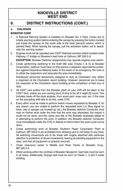
56
KNOXVILLE DISTRICT WEST END
9. DISTRICT INSTRUCTIONS (CONT.)
J. CALHOUNBOWATER CORP. 1. A Railroad Warning System is installed on Bowater No. 4 Track. Crews are to
initiate warning system before entering the canopy by pressing the button located just inside the canopy on the south side of the track (second column, which is painted Red). When leaving the canopy, pull the activation button out to deacti-vate the warning system.
2. Engines must not be operated over CSXT Railroad Junction switch located under Highway 11 bridge on Bowater’s lead track at Calhoun, MP 200.5 A.
EXCEPTION: Bowater Switcher assignments may operate engines over switch.3. Crews performing switching in the Kraft Mill area (Tracks 4 & 5) at Bowater
Corporation, Calhoun must have on their person a respirator approved for protec-tion against Hazardous Material leaks. In the event of an emergency, the crew is to utilize the respirators and evacuate the area immediately.
Extraboard personnel temporarily assigned to duty at Charleston may obtain a respirator at the Charleston report building. However, personnel are to leave the respirator at the Charleston report building at the completion of their tour of duty.
4. All CSXT cars pulled from the Bowater plant on your shift will be taken to the CSXT Yard, unless you are running short of time to be off in eight (8) hours. This includes loads off the dock empties, from wood yard, soap cars, etc. If the crew on the preceding shift fails to do this, notify CYO.
5. Every effort must be made to perform switch moves requested by Bowater. If, for any reason, you are unable to perform the requested work (i.e. Blue signal on track, clay or sparger car hooked-up, etc.) the Bowater switcher Conductor must note on his/her work order the time that the work was attempted, the reason it could not be done, and the name and title of the Bowater employee talked to in attempting to perform the work. In addition, the Bowater switcher Conductor must immediately notify the CYO in Atlanta to inform them the work could not be done.
6. Crews performing work at Bowater Southern Paper Corporation Plant at Calhoun, MP 200.6 A are prohibited from allowing cars to roll freely on any track. All switching movements are to be made with engine attached with particular attention to protection of shove movements, leaving all standing equipment in the clear, and that all equipment is properly secured.
7. Close clearance exists in Middle and River Tracks at Bowater Corp., MP 200.3 A.
8. While working within the confines of Bowater Newsprint, hard hats must be worn in all areas. Additionally, Orange vest must be worn on Tracks 1, 2 and 3 inside building.

57
KNOXVILLE DISTRICT WEST END
9. DISTRICT INSTRUCTIONS (CONT.)
K. CLEVELAND1. When trains are tied up at Cleveland and awaiting crews, consist and informa-
tion on where hand brakes are applied should be left in the crew room. All trains originating at Cleveland will receive their Train Clearance for their train off printer in crew room.
2. Edwards Street side of crew room is to remain locked, and track side of crew room is to be locked with switch lock when crew room is empty.
3. Crews will have to call Knoxville West End Dispatcher to have taxis sent to pick them up.
4. All Westward trains that swap out with Georgia Division crews at the Cleveland depot must hold back east of Fifteenth Street road crossing, MP 211.8 A, until verbal communication with the outbound crew has been obtained and the out-bound crew is ready to swap out and depart.
5. Central Division crews operating trains on the I Line that will not go south of MP 5.0 I will not be required to receive a Georgia Division Train Clearance. All slow orders and track restrictions between Bradley, MP 213.5 A and MP 5.0 I will be included on the Central Division Train Clearance.
6. Crews must contact the Operations Manager at ADM in Cleveland, TN, MP 213.0 A at 423-472-4102, prior to entering the facility.
7. When spotting Georgia Pacific, MP 209.0 A, no more than four (4) cars may be handled. A safety stop must be made at least one (1) car from bumping post, two (2) hand brakes must be applied prior to making final shove when spotting.
L. ROAD CROSSINGS Do not block the following crossings. Trains meeting at these locations must hold off crossings until opposing train arrives. Concord Avenue — MP 132.6 A Taylor’s Lane — MP 146.8 A A-Frame Crossing — MP 147.7 A Private Road Crossing — MP 164.0 A All crossings Cleveland
M. END-OF-TRAIN DEVICE — GRADESReference the identification of grades as required in NS-1 Rules for Equipment Operation and Handling, Rule A-31, End-Of-Train Device and revised NS-1 Rule L-241, to include instructions for descending grades of 1% or more.
In accordance with CFR Part 232, the following designated sections of track are identi-fied as average grades of:
2% or greater over a distance of 2 continuous miles or 1% or greater over a distance of 3 continuous miles:
KNOXVILLE DISTRICT West End
Eastward Westward None None

58
KNOXVILLE DISTRICT K&A LINE
WEST SIDINGS IN FEET MP STATION NOTE
WEST END DISPATCHER .........................................
131.1 A Knoxville ......................................................................... Y
0.0 KA K&A Jct.
12.1 KA Alcoa N. Plant
15.0 KA Alcoa
16.0 KA Maryville
1. RULES IN EFFECT Main TrackBetween RulesK&A Jct. and Maryville 171
2. MAXIMUM SPEEDS Main TrackBetween MPHMP 0.0 KA and MP 16.0 KA, Maryville 25 Except: MP 0.0 KA to MP 3.0 KA 10 MP 8.4 KA to MP 8.6 KA, Curves 10
3. CHECKING LOCOMOTIVE SPEED INDICATORTests for accuracy will be made at the following locations and Engineers will adjust speed in accordance with any inaccuracy.
LOCATION OF TEST MILE SIGNS: WESTWARD EASTWARD MP 1.0 KA to MP 2.0 KA MP 7.0 KA to MP 6.0 KA
NOTE: Tests for accuracy will be made at other locations in addition to those shown. Engineers will choose appropriate locations to check speed indicators.
4. DIESEL UNIT RATINGS DIESEL UNIT RATINGS IN TONS Group 1 Group 2 Group 3 Group 4 Group 5 Group 6
WestwardSevier Yard to Maryville 1850 2450 2950 3645 4050 4780
EastwardMaryville to Sevier Yard 2050 2750 3250 4050 4500 5310
A LINE 773

59
KNOXVILLE DISTRICT K&A LINE
5. LOCOMOTIVE AND CAR RESTRICTIONS
A. WEIGHT RESTRICTIONSLoaded 4-axle cars may be handled up to the weight shown provided the stenciled Load Limit (Weight of car and lading) is NOT exceeded. 286,000 lbs.
B. EQUIPMENT RESTRICTIONSTrailing tonnage must be limited on line segments as shown below, behind the following equipment:1. Empty Multi-level cars.2. Empty Intermodal single-platform flats and such loaded with empty trailers or
containers.3. Empty 85-foot-long or longer flats and such flat cars when loaded with empty
trailers or containers, or loaded with only one (1) trailer or container.4. Empty Intermodal single-axle truck flat car or such cars loaded with empty
trailers or containers.5. Empty single or multiple-unit double-stack (well) cars, or articulated single-
platform (spine) cars. Be governed by Appendix 1 in the System Timetable.
Maximum Safe Trailing Tonnage Southward/ Northward/ Line Segments Between Westward EastwardK&A Line Knoxville and Maryville Unrestricted Unrestricted
6. SWITCHES AND DERAILS
JUNCTIONS NON-INTERLOCKED
Milepost Location Line/R.R. 0.0 KA K&A Jct. A Line1.0 KA Beltline K&H R.R.
7. COMMUNICATION INFORMATION Channel 1 Channel 2 Base Station TX and RX TX (RX)Sharps Ridge 56-56 48 (09)
8. DETECTOR INSTRUCTIONSNone.
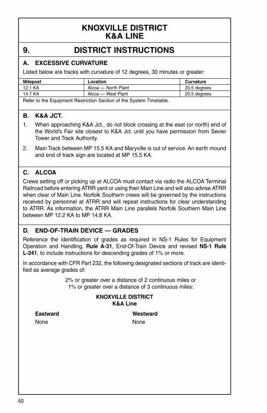
60
KNOXVILLE DISTRICT K&A LINE
9. DISTRICT INSTRUCTIONS
A. EXCESSIVE CURVATURE Listed below are tracks with curvature of 12 degrees, 30 minutes or greater:
Milepost Location Curvature 12.1 KA Alcoa — North Plant 20.5 degrees 14.7 KA Alcoa — West Plant 20.5 degrees Refer to the Equipment Restriction Section of the System Timetable.
B. K&A JCT.1. When approaching K&A Jct., do not block crossing at the east (or north) end of
the World’s Fair site closest to K&A Jct. until you have permission from Sevier Tower and Track Authority.
2. Main Track between MP 15.5 KA and Maryville is out of service. An earth mound and end of track sign are located at MP 15.5 KA.
C. ALCOA Crews setting off or picking up at ALCOA must contact via radio the ALCOA Terminal Railroad before entering ATRR yard or using their Main Line and will also advise ATRR when clear of Main Line. Norfolk Southern crews will be governed by the instructions received by personnel at ATRR and will repeat instructions for clear understanding to ATRR. As information, the ATRR Main Line parallels Norfolk Southern Main Line between MP 12.2 KA to MP 14.8 KA.
D. END-OF-TRAIN DEVICE — GRADESReference the identification of grades as required in NS-1 Rules for Equipment Operation and Handling, Rule A-31, End-Of-Train Device and revised NS-1 Rule L-241, to include instructions for descending grades of 1% or more.
In accordance with CFR Part 232, the following designated sections of track are identi-fied as average grades of:
2% or greater over a distance of 2 continuous miles or 1% or greater over a distance of 3 continuous miles:
KNOXVILLE DISTRICT K&A Line
Eastward Westward None None

61
KNOXVILLE DISTRICT COSTER LINE
NORTH SIDINGS IN FEET MP STATION NOTE
WEST END DISPATCHER .......................................... 3
0.0 C KNOXVILLE ................................................................. Y 1
0.5 C South End Two Tracks 2
2.3 C North End Two Tracks
2.5 C COSTER ................................................................. 2
STATION PAGE INFORMATIONNOTE 1: Knoxville Terminal governs Coster Line. NOTE 2: All trains must be have verbal authority from Sevier Main Tower before occupying
yard limits between Knoxville and Coster. NOTE 3: Knoxville District (KD) Dispatcher controls Knoxville to Coster between 8:00AM and
4:00PM Monday through Friday. Dispatcher DTMF Code 775.
1. RULES IN EFFECT Main Main 1 Main 2 Track Track TrackBetween Rules Knoxville and South End Two Tracks 93South End Two Tracks and Coster 93 93
2. MAXIMUM SPEEDS Main TracksBetween MPHMP 0.0 C, Knoxville and MP 2.3 C, Coster 15 Except: MP 0.0 C to MP 0.8 C 10 Auxiliary Tracks: North leg of Wye, Knoxville City Yard 5
3. CHECKING LOCOMOTIVE SPEED INDICATORNOTE: Engineers will choose appropriate locations to check speed indicators.
4. DIESEL UNIT RATINGSNone.
NB SB
A LINE
CO LINE C LINE
CPYL
YL
773

62
KNOXVILLE DISTRICT COSTER LINE
5. LOCOMOTIVE AND CAR RESTRICTIONS
A. WEIGHT RESTRICTIONSLoaded 4-axle cars may be handled up to the weight shown provided the stenciled Load Limit (Weight of car and lading) is NOT exceeded. 286,000 lbs.
B. EQUIPMENT RESTRICTIONSTrailing tonnage must be limited on line segments as shown below, behind the following equipment:1. Empty Multi-level cars.2. Empty Intermodal single-platform flats and such loaded with empty trailers or
containers.3. Empty 85-foot-long or longer flats and such flat cars when loaded with empty
trailers or containers, or loaded with only one (1) trailer or container.4. Empty Intermodal single-axle truck flat car or such cars loaded with empty
trailers or containers.5. Empty single or multiple-unit double-stack (well) cars, or articulated single-
platform (spine) cars. Be governed by Appendix 1 in the System Timetable.
Maximum Safe Trailing Tonnage Southward/ Northward/ Line Segments Between Westward EastwardCoster Line Knoxville and Coster Unrestricted Unrestricted
6. SWITCHES AND DERAILS
A. SPRING SWITCHESSpring switches are located as follows:Milepost Location Normal Position 2.3 C Coster, N. End Two Tracks Southward Main 0.5 C Coster, S. End Two Tracks Northward Main
B. JUNCTIONS INTERLOCKED
Milepost Location Line/R.R. 2.3 C Coster CO Line
NON-INTERLOCKEDMilepost Location Line/R.R. 0.0 C Knoxville A Line
7. COMMUNICATION INFORMATION Channel 1 Channel 2 Base Station TX and RX TX (RX)Sharps Ridge 56 48 (9)
8. DETECTOR INSTRUCTIONSNone.

63
KNOXVILLE DISTRICT COSTER LINE
9. DISTRICT INSTRUCTIONS
A. JOINT TRACKAGE Trains and engines of other divisions and foreign lines will use Central Division tracks as shows below: Between Willoughby Jct., MP 132.3 A and Coster Main Track, MP 2.3 C via
City Yard, CSXT and K&H Railroad.
B. COSTER 1. Close clearances exist at Coster Yard between Oakwood Tracks 1 and 2.
Employees are prohibited from riding on the side of equipment where adjacent track is occupied by equipment.
2. The following tracks at Coster Yard are designated as interchange tracks between Norfolk Southern and the Knoxville and Holston Railroad:
Oakwood No. 1 Oakwood No. 2 Equipment left standing on any of these tracks must have a minimum of five (5)
hand brakes applied. If train length or tonnage dictates, a sufficient amount above five (5) hand brakes will be required.
3. Standing equipment left on the Northward Main Line and Southward Main Line at Coster Shop, MP 2.0 C must have a minimum of four (4) hand brakes on the North End and four (4) hand brakes on the South end of the cut of standing equipment.
4. Due to the heavy grade and track condition, caution must be exercised prior to shoving cars northward out of Coster Yard through yard tracks. When in doubt as to train consist and amperage required for shove move, the safest course must be taken and the train should be moved in multiple cuts.
C. END-OF-TRAIN DEVICE — GRADESReference the identification of grades as required in NS-1 Rules for Equipment Operation and Handling, Rule A-31, End-Of-Train Device and revised NS-1 Rule L-241, to include instructions for descending grades of 1% or more.
In accordance with CFR Part 232, the following designated sections of track are identi-fied as average grades of:
2% or greater over a distance of 2 continuous miles or 1% or greater over a distance of 3 continuous miles:
KNOXVILLE DISTRICT Coster Line
Northward Southward None None
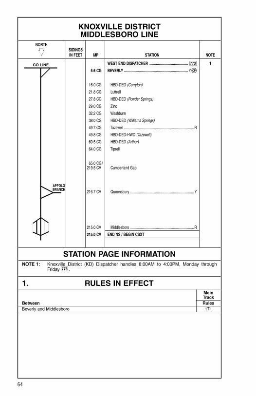
64
KNOXVILLE DISTRICT MIDDLESBORO LINE
NORTH SIDINGS IN FEET MP STATION NOTE
WEST END DISPATCHER ......................................... 1
5.6 CG BEVERLY .................................................................... Y
16.0 CG HBD-DED (Corryton)
21.8 CG Luttrell
27.8 CG HBD-DED (Powder Springs)
29.0 CG Zinc
32.2 CG Washburn
38.0 CG HBD-DED (Williams Springs)
49.7 CG Tazewell .......................................................................... R
49.8 CG HBD-DED-HWD (Tazewell)
60.5 CG HBD-DED (Arthur)
64.0 CG Tiprell
65.0 CG/ 219.5 CV Cumberland Gap
216.7 CV Queensbury .................................................................... Y
215.0 CV Middlesboro .................................................................... R
215.0 CV END NS / BEGIN CSXT
STATION PAGE INFORMATIONNOTE 1: Knoxville District (KD) Dispatcher handles 8:00AM to 4:00PM, Monday through
Friday 775 .
1. RULES IN EFFECT Main TrackBetween RulesBeverly and Middlesboro 171
CO LINE
APPOLO BRANCH
773
CP

65
KNOXVILLE DISTRICT MIDDLESBORO LINE
2. MAXIMUM SPEEDS Main TrackBetween MPHMP 5.6 CG, Beverly and MP 65.5 CG, Cumberland Gap 30 Except: MP 5.9 CG to MP 6.3 CG (Wye), Curves 15 MP 32.9 CG to MP 34.6 CG, Curves 25 MP 34.6 CG to MP 35.0 CG, Curves 15 MP 40.2 CG to MP 40.5 CG, Curves 25 MP 40.5 CG to MP 41.2 CG, Curves 15 MP 40.5 CG, Through Tunnel 15 MP 40.9 CG to MP 60.3 CG, Curves 25 MP 42.0 CG, Through Tunnel 15 MP 46.9 CG, Through Tunnel 15 MP 48.5 CG to MP 49.6 CG, Over Street Crossings 20 MP 54.4 CG to MP 55.0 CG, Curves 20 MP 58.5 CG to MP 58.9 CG, Curves 20MP 219.5 CV, Cumberland Gap and MP 215.8 CV 15 Except: MP 219.5 CV to MP 218.7 CV, Through Cumberland Gap Tunnel 10MP 215.8 CV and MP 215.0 CV 10
3. CHECKING LOCOMOTIVE SPEED INDICATORTests for accuracy will be made at the following locations and Engineers will adjust speed in accordance with any inaccuracy.
LOCATION OF TEST MILE SIGNS: NORTHWARD SOUTHWARD MP 8.0 CG to MP 9.0 CG MP 62.0 CG to MP 61.0 CG
NOTE: Tests for accuracy will be made at other locations in addition to those shown. Engineers will choose appropriate locations to check speed indicators.
4. DIESEL UNIT RATINGS DIESEL UNIT RATINGS IN TONS Group 1 Group 2 Group 3 Group 4 Group 5 Group 6
NorthwardSevier Yard to Middlesboro 1250 1650 2400 2475 2750 3250
SouthwardMiddlesboro to Tazewell 1150 1550 1850 2250 2500 2950 Tazewell to Washburn 1450 1950 2300 2880 3200 3780 Washburn to Sevier Yard 2600 3450 4150 5130 5700 6730

66
KNOXVILLE DISTRICT MIDDLESBORO LINE
5. LOCOMOTIVE AND CAR RESTRICTIONS
A. WEIGHT RESTRICTIONSLoaded 4-axle cars may be handled up to the weight shown provided the stenciled Load Limit (Weight of car and lading) is NOT exceeded. 286,000 lbs.
B. EQUIPMENT RESTRICTIONSTrailing tonnage must be limited on line segments as shown below, behind the following equipment:1. Empty Multi-level cars.2. Empty Intermodal single-platform flats and such loaded with empty trailers or
containers.3. Empty 85-foot-long or longer flats and such flat cars when loaded with empty
trailers or containers, or loaded with only one (1) trailer or container.4. Empty Intermodal single-axle truck flat car or such cars loaded with empty
trailers or containers.5. Empty single or multiple-unit double-stack (well) cars, or articulated single-
platform (spine) cars. Be governed by Appendix 1 in the System Timetable.
Maximum Safe Trailing Tonnage Southward/ Northward/ Line Segments Between Westward EastwardMiddlesboro Line Sevier Yard and Middlesboro Unrestricted Unrestricted
6. SWITCHES AND DERAILS
JUNCTIONS INTERLOCKED
Milepost Location Line/R.R. 5.6 CG Beverly CO Line
NON-INTERLOCKEDMilepost Location Line/R.R. 215.0 CV Middlesboro CSXT 216.7 CV Queensbury MR Line 5.6 CG Beverly CO Line
7. COMMUNICATION INFORMATION Channel 1 Channel 2 Base Station TX and RX TX (RX)Tazewell 56 NAMiddlesboro 56 NA
8. DETECTOR INSTRUCTIONSNone.

67
KNOXVILLE DISTRICT MIDDLESBORO LINE
9. DISTRICT INSTRUCTIONS
A. JOINT TRACKAGE Trains and engines of other divisions and foreign lines will use Central Division tracks as shown below: Between Middlesboro, MP 215.0 CV and Queensbury, MP 216.7 CV, CSXT.
B. BEVERLYDue to curve restrictions, cars for Beverly Steel will not be set off or picked up on the industry’s loading track, MP 6.5 CG. Crews will pickup and set off cars for Beverly Steel on the Beverly Runaround Track just north of the loading track switch.
C. LUTTRELL, TN, O-N MINERALS 1. Employees are prohibited from riding on equipment past pit, located on Stone
Track, O-N Minerals, MP 24.0 CG.
2. Do not block road crossings at south end of O-N Minerals, MP 23.6 CG, while setting out at O-N Minerals.
3. When spotting cars at O-N Minerals, stop short of tipple.
D. WASHBURN Before engines pass the loadout conveyor for Washburn, TN, the extension for the conveyor must be in the “UP” position, and it must be determined proper clearance exists.
E. MIDDLESBORO Cars and engines left standing in Middlesboro Yard must have a minimum of two (2) hand brakes.
F. END-OF-TRAIN DEVICE — GRADESReference the identification of grades as required in NS-1 Rules for Equipment Operation and Handling, Rule A-31, End-Of-Train Device and revised NS-1 Rule L-241, to include instructions for descending grades of 1% or more.
In accordance with CFR Part 232, the following designated sections of track are identi-fied as average grades of:
2% or greater over a distance of 2 continuous miles or 1% or greater over a distance of 3 continuous miles:
KNOXVILLE DISTRICT Middlesboro Line
Northward Southward MP 32.2 CG to MP 35.2 CG = 1.04% MP 32.2 CG to MP 27.2 CG = 1.00% MP 36.0 CG to MP 39.0 CG = 1.00% MP 48.7 CG to MP 42.5 CG = 1.42% MP 50.9 CG to MP 56.9 CG = 1.36% MP 60.4 CG to MP 57.0 CG = 1.00%
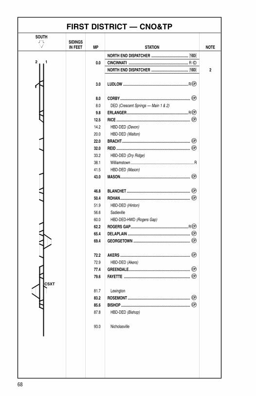
68
FIRST DISTRICT — CNO&TP SOUTH SIDINGS IN FEET MP STATION NOTE
NORTH END DISPATCHER .......................................
0.0 CINCINNATI ............................................................... R
NORTH END DISPATCHER ....................................... 2
3.0 LUDLOW .....................................................................R
8.0 CORBY ..........................................................................
8.0 DED (Crescent Springs — Main 1 & 2)
9.8 ERLANGER .................................................................R
12.5 RICE ..............................................................................
14.2 HBD-DED (Devon)
20.0 HBD-DED (Walton)
22.0 BRACHT ........................................................................
32.0 REID ..............................................................................
33.2 HBD-DED (Dry Ridge)
38.1 Williamstown ................................................................... R
41.5 HBD-DED (Mason)
43.0 MASON ..........................................................................
46.8 BLANCHET ...................................................................
50.4 ROHAN ..........................................................................
51.9 HBD-DED (Hinton)
56.6 Sadieville
60.0 HBD-DED-HWD (Rogers Gap)
62.2 ROGERS GAP .............................................................R
65.4 DELAPLAIN ..................................................................
69.4 GEORGETOWN ............................................................
72.2 AKERS ..........................................................................
72.9 HBD-DED (Akers)
77.4 GREENDALE .................................................................
79.6 FAYETTE ......................................................................
81.7 Lexington
83.2 ROSEMONT ..................................................................
85.6 BISHOP .........................................................................
87.8 HBD-DED (Bishop)
93.0 Nicholasville
2 1
CSXT
103
CP
CP
CP
CP
CP
CP
CP
CP
CP
CP
CP
CP
CP
CP
CP
CP
CP
103

69
FIRST DISTRICT — CNO&TP SOUTH SIDINGS IN FEET MP STATION NOTE
NORTH END DISPATCHER .......................................
95.7 JESSAMINE ..................................................................
98.2 WILMORE ....................................................................R
98.4 HBD-DED (Wilmore — Main 1 & 2)
102.5 HIGH BRIDGE ...............................................................
105.0 BROWN .........................................................................
109.0 Burgin
109.0 HBD-DED (Burgin)
110.7 FAULKNER .................................................................... 1
112.6 N. WYE ........................................................................ Y
113.2 S. J. TOWER ................................................................ Y
116.4 DV TOWER .............................................................
116.6 Danville ....................................................................... Y, R
STATION PAGE INFORMATIONNOTE 1: Danville Terminal section governs between Faulkner and South Danville. NOTE 2: Cincinnati Terminal section governs between Cincinnati and Ludlow.
1. RULES IN EFFECT Main Main 1 Main 2 Track Track TrackBetween Rules Gest Street and 8th Street 261 2618th Street and Ludlow 261 261Ludlow and Rice 261 261Rice and Bracht 261Bracht and Reid 261 261Reid and Mason 261Mason and Rohan 261 261Rohan and Rogers Gap 261Rogers Gap and Akers 261 261Akers and Greendale 261Greendale and Bishop 261 261Bishop and Jessamine 261Jessamine and Brown 261 261Brown and Faulkner 261Faulkner and DV Tower 261 261
2 1
W LINE
CPYL
103
CP
CP
CP
CP
CP
CP
CP

70
FIRST DISTRICT — CNO&TP
2. MAXIMUM SPEEDS TV Frt.Between MPHMP 0.0, Cincinnati and MP 2.6 10 10MP 2.6 and MP 116.4, DV Tower 60 50 Except: MP 2.6, Through Turnout C.U.T. Switch 15 15 MP 2.6 to MP 3.0, Ohio River Bridge 20 20 MP 3.0, Through Crossover Ludlow 25 25 MP 3.0 to MP 8.0 25 25 MP 8.0 to MP 13.5, Curves 55 50 MP 9.8, Through Crossover Erlanger 40 40 MP 12.5, Through Turnout Rice 40 40 MP 18.8 to MP 25.0, Curves 55 50 MP 22.0, Through Turnout Bracht 40 40 MP 29.2 to MP 38.6, Curves 55 50 MP 32.0, Through Turnout Reid 40 40 MP 38.6 to MP 45.6, Curves 50 45 MP 43.0, Through Turnout Mason 40 40 MP 45.6 to MP 51.5, Curves 55 50 MP 46.8, Through Crossovers Blanchet 40 40 MP 50.4, Through Turnout Rohan 40 40 MP 51.5 to MP 51.8, Curves 50 45 MP 51.8 to MP 55.0, Curves 55 50 MP 55.0 to MP 55.3, Curves 50 45 MP 55.3 to MP 56.3, Curves 45 45 MP 56.7 to MP 59.1, Curves 55 50 MP 62.2, Through Turnout Rogers Gap 40 40 MP 65.4, Through Crossovers Delaplain 40 40 MP 69.4, Through Crossovers Georgetown 40 40 MP 72.2, Through Turnout Akers 40 40 MP 77.4, Through Turnout Greendale 40 40 MP 79.6, Through Crossovers Fayette 40 40 MP 81.5 to MP 81.8, Curves 35 35 MP 81.8 to MP 82.0, Curves 40 40 MP 82.4 to MP 83.2, over street crossing engine only 40 40 MP 83.2, Through Crossovers Rosemont 40 40 MP 85.6, Through Turnout Bishop 40 40 MP 95.7, Through Turnout Jessamine 40 40 MP 98.2, Through Crossovers Wilmore 40 40

71
FIRST DISTRICT — CNO&TP
2. MAXIMUM SPEEDS (CONT.) TV Frt.Between MPH MP 101.6 to MP 102.7, Curves 55 50 MP 102.5, Through Crossovers High Bridge 40 40 MP 102.7 to MP 103.0, Curves 45 45 MP 103.0 to MP 103.5, Kentucky River Bridge 40 40 MP 103.5 to MP 103.7, Curves 45 45 MP 103.7 to MP 104.6, Curves 50 50 MP 105.0, Through Turnout Brown 40 40 MP 105.6 to MP 106.0, Curves 55 50 MP 106.0 to MP 106.5, Curves 50 45 MP 108.3 to MP 108.6, Curves 55 50 MP 110.7, Through Turnout Faulkner 40 40 MP 112.6 Through Turnout N. Wye Louisville District 20 20 MP 113.2, Through Crossovers from CNOTP No. 1 to the Louisville District Main Track 40 40 MP 113.2, Through Crossover SJ Tower 40 40 MP 113.3, Through Turnout S. Wye (Louisville District) 40 40 MP 114.0 to MP 116.0, Curves 55 50 MP 116.0 to MP 116.5, Curves 50 50Auxiliary Tracks: Cincinnati, MP 0.0 — All yard tracks 10 10 Erlanger, MP 9.8 — All yard tracks 10 10 Delaplain, MP 65.4 — All yard tracks 15 15 Old Georgetown Yard, MP 69.5 — All Tracks 10 10 Lexington, MP 81.7 — All yard tracks 10 10
3. CHECKING LOCOMOTIVE SPEED INDICATORTests for accuracy will be made at the following locations and Engineers will adjust speed in accordance with any inaccuracy.
LOCATION OF TEST MILE SIGNS: SOUTHWARD NORTHWARD MP 21.0 to MP 22.0 MP 108.0 to MP 107.0 MP 30.0 to MP 31.0 MP 76.0 to MP 75.0 MP 86.0 to MP 87.0
NOTE: Engineers will choose appropriate locations to check speed indicators as necessary.
4. DIESEL UNIT RATINGS DIESEL UNIT RATINGS IN TONS Group 1 Group 2 Group 3 Group 4 Group 5 Group 6
SouthwardCincinnati to Erlanger 1600 2150 2550 3150 3500 4130 Erlanger to Danville 3700 4950 5900 7335 8150 9620
NorthwardDanville to Cincinnati 3550 4750 5650 7020 7800 9200
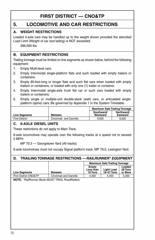
72
FIRST DISTRICT — CNO&TP
5. LOCOMOTIVE AND CAR RESTRICTIONS
A. WEIGHT RESTRICTIONSLoaded 4-axle cars may be handled up to the weight shown provided the stenciled Load Limit (Weight of car and lading) is NOT exceeded. 286,000 lbs.
B. EQUIPMENT RESTRICTIONSTrailing tonnage must be limited on line segments as shown below, behind the following equipment:1. Empty Multi-level cars.2. Empty Intermodal single-platform flats and such loaded with empty trailers or
containers.3. Empty 85-foot-long or longer flats and such flat cars when loaded with empty
trailers or containers, or loaded with only one (1) trailer or container.4. Empty Intermodal single-axle truck flat car or such cars loaded with empty
trailers or containers.5. Empty single or multiple-unit double-stack (well) cars, or articulated single-
platform (spine) cars. Be governed by Appendix 1 in the System Timetable.
Maximum Safe Trailing Tonnage Southward/ Northward/ Line Segments Between Westward EastwardFirst District Cincinnati and Danville 9,000 8,200
C. 6-AXLE DIESEL UNITS These restrictions do not apply to Main Track.
6-axle locomotives may operate over the following tracks at a speed not to exceed 5 MPH: MP 70.3 — Georgetown Yard (All tracks)
6-axle locomotives must not occupy Signal platform track, MP 79.0, Lexington Yard.
D. TRAILING TONNAGE RESTRICTIONS —RAILRUNNER* EQUIPMENT Maximum Safe Trailing Tonnage Empty Loaded Less than Light Load 28 Tons Line Segments Between 18 Tons 18–27 Tons or MoreFirst District CNO&TP Cincinnati and Danville 4,400 4,400 5,200NOTE: *RailRunner Block MUST TRAIL RoadRailers.

73
FIRST DISTRICT — CNO&TP
6. SWITCHES AND DERAILS
JUNCTIONS INTERLOCKED
Milepost Location Line/R.R. 112.6 N. Wye Louisville District113.2 SJ Tower Louisville District
NON-INTERLOCKEDMilepost Location Line/R.R. 80.9 Lexington RJCC
7. COMMUNICATION INFORMATION Channel 1 Channel 2 Base Station TX and RX TX (RX)Ludlow 56 48 (9)Erlanger 56 48 (9)Williamstown 56 48 (9)Muddy Ford 56 48 (9)Wilmore 56 48 (9)Harrodsburg 56 48 (9)
8. DETECTOR INSTRUCTIONSNone.
9. DISTRICT INSTRUCTIONS
A. EXCESSIVE CURVATURE Listed below are tracks with curvature of 12 degrees, 30 minutes or greater:
Milepost Location Curvature 11.8 Continental Pet 14.0 degrees 12.5 Equitable Bag (Inside track) 24.0 degrees 12.5 Natico 13.5 degrees 12.5 Industrial Lead 16.5 degrees 12.5 United Handling Service Lead 14.0 degrees 12.5 CTW Rice 14.0 degrees 13.2 84 Lumber Track 14.0 degrees 16.6 Verst Group 18.0 degrees 16.6 CTW 18.0 degrees 16.6 Merchants Cold Storage 16.0 degrees 16.6 Rossevelt Paper 17.0 degrees 36.9 Phillips Drisco Pipe 21.0 degrees 93.3 Gulf States Paper 16.0 degrees 93.4 Atlantis Plastics 14.0 degrees Refer to the Equipment Restriction Section of the System Timetable.

74
FIRST DISTRICT — CNO&TP
9. DISTRICT INSTRUCTIONS (CONT.)
B. CRESCENT SPRINGS Normal position of the Queen City Paper, Prime source switch is lined for movement from Arling Lumber to Queen City Paper, Sequoia.
C. ERLANGER Crews switching at Erlanger must not request for the southward signal at Erlanger until movement is ready to enter limits of interlocking, and must clear the limits of interlocking as soon as possible. Notify Train Dispatcher when the signal is no longer needed if movement stops short of signal, or movement clears interlocking after making switching move. Switching should be arranged to prevent fouling interlocking limits unnecessarily.
Crews switching cars on Main Track and in yard tracks at Erlanger must have a minimum of four (4) hand brakes applied on the north end of track when other cars are allowed to roll free to a coupling on these tracks. Four (4) hand brakes are required due to severity of descending grade to the north. No more than two (2) cars that are allowed to be cut off in motion will be allowed to roll free when performing switching operations at Erlanger.
At Arling Lumber Track, MP 8.0 do not spot cars closer than 25 feet from end of track. An Orange line has been painted 25 feet from end of track. Do Not shove lead wheels past this line when spotting cars at Arling Lumber.
D. RICE The normal position for switches off the set off track at Rice, KY, MP 12.5 will be lined and locked for movement on the set off track. These switches must be left in normal position after use.
E. RICHWOOD When dropping cars at Georgia Pacific, MP 14.7 the cars must be cut off at the out-side track switch and allowed to roll to outside track only. When switching Georgia Pacific, MP 14.7 do not couple to cars inside building until both doors of the building are open.
Trains and engines handling or switching cars on Richwood lead or Richwood Runaround Track, MP 16.6 must have air hoses coupled and cut in on all cars and between locomotive and cars. A car(s) with defective air brakes must not be left standing on either track unless coupled to other cars that have brakes applied. In addition, notification of defective air brake must be made to the proper authority. Air brakes on all cars must be fully charged prior to making any switching moves on either of these tracks. Cars left standing on either of these tracks must have a hand brake applied on each car.

75
FIRST DISTRICT — CNO&TP
9. DISTRICT INSTRUCTIONS (CONT.)
F. DELAPLAIN / GEORGETOWNEmployees must not ride on east side of cars and/or engines on Thoroughfare Lead while passing PY-1 intermodal loading/unloading track account close clearance when intermodal stacker is loading/unloading trailers/containers at Delaplain, MP 65.5. Conductor must confer with the Delaplain Yard office, during open hours, or CYO Atlanta prior to setting off or picking up after hours at Delaplain. This is to ensure that there is a clear understanding as to where set off is to be made and what cars are to be picked up. Trains picking up at Delaplain (Toyota) will arrange to do so as follows:
1. Obtain a list of the traffic (cars) to be picked up. The list may be obtained from the CYO Atlanta. The list may be obtained via radio or in writing.
2. Crews picking up at Delaplain will check the pickup list with the cars being picked-up.
Train will not leave Delaplain until all cars on pickup list have been added to their train unless otherwise instructed by proper authority. Any exceptions to the pickup list must be immediately called to the attention of CYO Atlanta before leaving. Trains or Engines performing work at Delaplain must not enter the north or south end of the yard without first getting permission from the Conductor of the Job working the yard. Southern Yard Channel (TX 92 — RX 92), or NW #2 Channel, (TX-76 — RX 76). If no crew is on-duty, permission must be received from the Train Dispatcher.
Job No. On-Duty Days Utility On-Duty DaysT61 — 76-76 (5) 7:00AM — M–F GU01 7:00AM M–FT64 — 92-92 (3) 5:00AM — M–F GU02 6:00PM M–Sat.T14 — 92-92 (3) 1:00PM — M–FT63 — 92-92 (3) 9:00PM — S–F239 — 76-76 (5) 7:00PM — M–ST60 — 76-76 (5) 10:00PM — M–F
When placing or pulling cars from Toyota Tsusho, only the outside track may be used. Toyota Tsusho performs their own switching.
Close clearance exists at doors and through building at Green Metals Industry, MP 64.0. NS engines are not permitted to enter the building because of overhead clearances.
Single cars are not to be left standing on any track at Delaplain Yard. Single car setoffs must be coupled to another car or cars.
Trains setting off intermodal traffic at Georgetown, KY, will arrange to spot cars at the unloading facility (Tracks PY01 or PY02) on arrival as directed by CYO in Atlanta.
Riding of cars is prohibited at Green Metals Industry, MP A 64.0, Georgetown, KY, due to close clearance between the tracks.
Close clearance exists on the curve at the north end of the Support Yard, Delaplain, KY, SY10 and SY11. Employees are prohibited from riding equipment at this location.

76
FIRST DISTRICT — CNO&TP
9. DISTRICT INSTRUCTIONS (CONT.)
G. LEXINGTON Due to close clearance, employees must not ride on the side of equipment between Tracks No. 3, 4, and 5 when equipment is standing on adjacent track on CSXT inter-change tracks, Lexington, MP 80.1. When delivering an empty coal train to the CSXT interchange, the rear car must be left a minimum of one (1) car length from the CSXT derail protecting CSXT Main Line. Sufficient hand brakes must be applied on the south end.
After completing your switching in Lexington Yard, all tracks where cars were switched into must be checked to assure that the track is solid (all couplings made) and cars are properly secured. If cars are blocked for a pickup, all air hose couplings must be made and angle cock closed on rear of cut.
Conductors working Atlantis Plastic Industry in Nicholasville, KY are to contact CYO before entering Industry and have them contact Atlantis to unhook their hoses.
Road crews must contact the CYO Atlanta or local crew on-duty before entering the yard at Lexington. Crews may be on-duty there between:
4:00PM–4:00AM Sunday and Monday 6:00AM–4:00AM Tuesday through Thursday 6:00AM–6:00PM Friday and Saturday
If unable to contact yard crews during these times, contact the North End Dispatcher to verify if crew is on-duty and in the yard. Southern Yard Channel TX 92 — RX 92, or NW #2 Channel TX 76 — RX 76.
Account severity of descending grade to the North, when cars are allowed to roll free and couple to standing cars, the standing cars must be a minimum of 100 feet from the clearance point on the north end of track and a minimum of four (4) hand brakes applied to the northernmost cars.
No cars exceeding 50' can occupy the Signal Platform Track, MP 79.0, Lexington Yard.
H. NICHOLASVILLE Due to insufficient clearance for excessive dimension loads wider than 12 feet 10 inches, engines, cars or track equipment must not be left standing adjacent to the Main Track on the portion of the curve track between MP 92.5 and MP 92.8.
I. BROWN Normal position of switch, north end of Lower yard, Brown to Brown Steam Plant, is lined and locked for movement to coal plant. Main crossing at Kentucky Utilities must not be blocked unnecessarily. If the crossing will be blocked 10 minutes, arrange-ments must be made to cut the train and clear the crossing.
Normal positon of switch, south end of Lower yard is to be lined for Track No. 3 when possible. Cars should be stored on Tracks No. 2 or 4.

77
FIRST DISTRICT — CNO&TP
9. DISTRICT INSTRUCTIONS (CONT.)
J. FAULKNER All southward trains must contact Danville Tower before fouling Faulkner Road crossing, MP 112.2.
K. END-OF-TRAIN DEVICE — GRADESReference the identification of grades as required in NS-1 Rules for Equipment Operation and Handling, Rule A-31, End-Of-Train Device and revised NS-1 Rule L-241, to include instructions for descending grades of 1% or more.
In accordance with CFR Part 232, the following designated sections of track are identi-fied as average grades of:
2% or greater over a distance of 2 continuous miles or 1% or greater over a distance of 3 continuous miles:
FIRST DISTRICT CNO&TP
Northward Southward MP 8.0 to MP 3.2 = 1.13% None
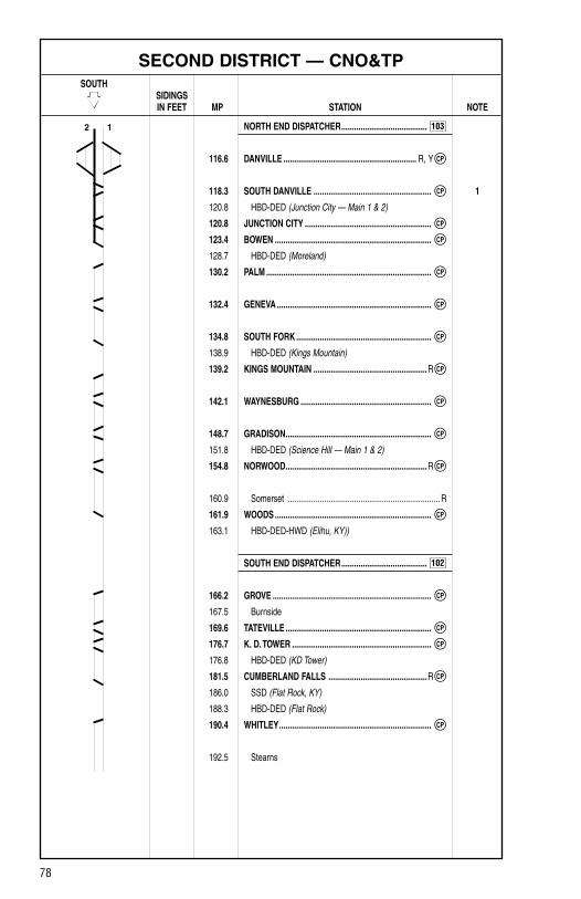
78
SECOND DISTRICT — CNO&TP SOUTH SIDINGS IN FEET MP STATION NOTE
NORTH END DISPATCHER ........................................
116.6 DANVILLE .............................................................. R, Y
118.3 SOUTH DANVILLE ....................................................... 1
120.8 HBD-DED (Junction City — Main 1 & 2)
120.8 JUNCTION CITY ...........................................................
123.4 BOWEN .........................................................................
128.7 HBD-DED (Moreland)
130.2 PALM .............................................................................
132.4 GENEVA ........................................................................
134.8 SOUTH FORK ...............................................................
138.9 HBD-DED (Kings Mountain)
139.2 KINGS MOUNTAIN .....................................................R
142.1 WAYNESBURG .............................................................
148.7 GRADISON ....................................................................
151.8 HBD-DED (Science Hill — Main 1 & 2)
154.8 NORWOOD ..................................................................R
160.9 Somerset ....................................................................... R
161.9 WOODS .........................................................................
163.1 HBD-DED-HWD (Elihu, KY))
SOUTH END DISPATCHER ........................................
166.2 GROVE ..........................................................................
167.5 Burnside
169.6 TATEVILLE ....................................................................
176.7 K. D. TOWER .................................................................
176.8 HBD-DED (KD Tower)
181.5 CUMBERLAND FALLS ..............................................R
186.0 SSD (Flat Rock, KY)
188.3 HBD-DED (Flat Rock)
190.4 WHITLEY .......................................................................
192.5 Stearns
2 1
CP
103
CP
CP
CP
CP
CP
CP
CP
CP
CP
CP
CP
102
CP
CP
CP
CP
CP

79
SECOND DISTRICT — CNO&TP SOUTH SIDINGS IN FEET MP STATION NOTE
SOUTH END DISPATCHER ........................................
194.7 REVILO ..........................................................................
201.1 HBD-DED (Silerville — Main 1 & 2)
202.4 RATLIFF ........................................................................
209.4 Oneida ........................................................................ Y, R
211.5 PEMBERTON ................................................................
211.8 HBD-DED (Pemberton — Main 1 & 2)
215.3 Helenwood
215.4 PHILLIPS .......................................................................
221.9 ROBBINS ......................................................................
225.8 GLEN MARY .................................................................
226.0 HBD-DED (Glen Mary — Main 1 & 2)
231.4 SUNBRIGHT ................................................................R
234.9 HBD-DED (Pilot Mountain — Main 1 & 2)
241.5 LANCING .......................................................................
241.8 HBD-DED (Lancing, TN — Main 1 & 2)
244.2 C. W. TOWER .................................................................
249.0 COLEMAN .....................................................................
251.2 CAMP AUSTIN ..............................................................
251.3 HBD-DED (Camp Austin — Main 1 & 2)
252.7 NORTH OAKDALE ........................................................
254.4 Oakdale .......................................................................... R
STATION PAGE INFORMATIONNOTE 1: Danville Terminal section governs between Faulkner and South Danville.
2 1 102
CP
CP
CP
CP
CP
CP
CP
CP
CP
CP
CP
CP

80
SECOND DISTRICT — CNO&TP
1. RULES IN EFFECT Main Main 1 Main 2 Track Track TrackBetween Rules D.V. Tower and South Danville 93 93South Danville and Bowen 261 261Bowen and Palm 261Palm and South Fork 261 261South Fork and Kings Mountain 261Kings Mountain and Woods 261 261Woods and Grove 261Grove and Cumberland Falls 261 261Cumberland Falls and Whitley 261Whitley and Phillips 261 261Phillips and Robbins 261Robbins and CW Tower 261 261CW Tower and Coleman 261Coleman and Oakdale 261 261

81
SECOND DISTRICT — CNO&TP
2. MAXIMUM SPEEDS TV Frt.Between MPHMP 116.4 and MP 118.3 30 30 Except: MP 116.4 to MP 118.3, Restricted Speed entering, leaving, or using No. 1 & No. 2 Tracks between the points designated until the leading end of the movement reaches the governing signal at DV Tower or South Danville MP 118.3, Danville and MP 254.4, Oakdale 60 50 Except: MP 118.3 Through Crossovers South Danville 40 40 MP 118.8 to MP 119.0, Curves 50 50 MP 120.8, Through Crossovers Junction City 40 40 MP 123.4, Through Turnout Bowen 40 40 MP 130.2, Through Turnout Palm 40 40 MP 130.1 to MP 130.5, Curves 55 50 MP 132.4, Through Crossovers Geneva 40 40 MP 134.3 to MP 134.7, Curves 50 45 MP 134.8, Through Turnout South Fork 40 40 MP 135.0 to MP 135.2, Curves 50 45 MP 135.2 to MP 136.0, Curves 40 40 MP 136.0 to MP 137.1, Curves 50 45 MP 137.6 to MP 141.1, Curves 55 50 MP 139.2, Through Turnout Kings Mountain 40 40 MP 142.1, Through Crossovers Waynesburg 40 40 MP 148.7, Through Crossovers Gradison 40 40 MP 150.3 to MP 150.7, Curves 55 50 MP 152.5 to MP 156.9, Curves 50 45 MP 154.8, Through Crossovers Norwood 40 40 MP 156.9 to MP 158.8, Curves 55 50 MP 158.8 to MP 159.2, Curves 50 45 MP 159.2 to MP 160.2, Curves 50 50 MP 160.2 to MP 160.5, Curves 40 40 MP 160.5 to MP 161.9, Curves 55 50 MP 161.9, Through Turnout Woods 40 40 MP 163.2 to MP 163.5, Curves 45 45 MP 163.5 to MP 163.7, Curves 40 40 MP 165.3 to MP 166.2, Curves 55 50 MP 166.2, Through Turnout Grove 40 40 MP 166.2 to MP 168.1, Curves 45 45 MP 166.8, Cumberland River Bridge 45 45 MP 168.1 to MP 168.9, Curves 40 40 MP 169.6, Through Crossovers Tateville 40 40 MP 177.7, Through Crossovers KD Tower 40 40 MP 179.5 to MP 180.0, Curves 35 35 MP 180.0 to MP 181.0, Curves 40 40 MP 181.1 to MP 182.4, Curves 55 50 MP 181.5, Through Turnout Cumberland Falls 40 40 MP 186.5 to MP 187.3, Curves 50 45 MP 187.3 to MP 187.7, Curves 40 40 MP 187.7 to MP 188.2, Curves 50 45 MP 188.0 (Southward 5 or 6 unit radio trains) 40 40 MP 188.6 to MP 191.7, Curves 55 50 MP 190.4, Through Turnout Whitley 40 40

82
SECOND DISTRICT — CNO&TP
2. MAXIMUM SPEEDS (CONT.) TV Frt.Between MPH MP 192.0 (All southward radio trains) 40 40 MP 192.0 to MP 192.4, Curves 50 50 MP 192.4 to MP 193.3, Curves 50 45 MP 193.3 to MP 194.4, Curves 40 40 MP 194.4 to MP 194.8, Curves 45 45 MP 194.7, Through Crossovers Revilo 40 40 MP 194.8 to MP 195.2, Curves 50 50 MP 195.5 to MP 195.7, Curves 55 50 MP 202.4, Through Crossovers Ratliff 40 40 MP 203.4 to MP 203.7, Curves 55 50 MP 204.4 (All northward radio trains) 45 45 MP 205.2 to MP 206.0, Curves 50 50 MP 206.0 to MP 206.4, Curves 45 40 MP 207.7 to MP 208.0, Curves 45 45 MP 211.9 to MP 212.3, Curves 55 50 MP 211.5, Through Crossovers Pemberton 40 40 MP 215.4, Through Turnout Phillips 40 40 MP 217.7 to MP 218.0, New River Bridge 40 40 MP 221.9, Through Turnout Robbins 40 40 MP 222.0 to MP 222.7, Curves 40 40 MP 222.7 to MP 223.7, Curves 35 35 MP 223.7 to MP 226.5, Curves 40 40 MP 225.8, Through Crossovers Glen Mary 40 40 MP 226.5 to MP 227.9, Curves 45 45 MP 227.9 to MP 229.5, Curves 40 40 MP 229.5 to MP 232.2, Curves 45 45 MP 231.4, Through Crossovers Sunbright 40 40 MP 232.2 to MP 233.7, Curves 50 45 MP 233.7 to MP 235.2, Curves 50 50 MP 235.2 to MP 237.6, Curves 40 40 MP 237.6 to MP 238.8, Curves 45 45 MP 238.8 to MP 239.5, Curves 35 35 MP 239.5 to MP 240.4, Curves 45 45 MP 240.4 to MP 241.5, Curves 40 40 MP 241.5 to MP 244.3, Track No. 1 25 25 MP 241.5 to MP 244.3, Track No. 2 40 40 MP 241.5, Through Crossovers Lancing 40 40 MP 244.2, Through Turnout CW Tower 40 40 MP 244.3 to MP 246.3, Curves 45 45 MP 246.8 to MP 248.2, Curves 55 50 MP 249.0, Through Turnout Coleman 40 40 MP 251.0 to MP 251.3, Curves 40 40 MP 251.2, Through Crossovers Camp Austin 40 40 MP 251.3 to MP 252.1, Curves 35 35 MP 252.1 to MP 254.4, Curves 45 45 MP 252.7, Through Crossover North Oakdale 15 15Auxiliary Tracks: West Lead from Clarksrun Bridge to South Danville 20 20 MP 254.5, No. 2 Over Switch with engines only 20 20 Operate at Restricted Speed until leading end of movement reaches governing signal at South Danville.

83
SECOND DISTRICT — CNO&TP
3. CHECKING LOCOMOTIVE SPEED INDICATORTests for accuracy will be made at the following locations and Engineers will adjust speed in accordance with any inaccuracy.
LOCATION OF TEST MILE SIGNS: SOUTHWARD NORTHWARD MP 124.0 to MP 125.0 MP 249.0 to MP 248.0 MP 129.0 to MP 130.0 MP 238.0 to MP 237.0 MP 138.0 to MP 139.0 MP 218.0 to MP 217.0 MP 147.0 to MP 148.0 MP 204.0 to MP 203.0 MP 148.0 to MP 149.0 MP 217.0 to MP 218.0
NOTE: Tests for accuracy will be made at other locations in addition to those shown. Engineers will choose appropriate locations to check speed indicators.
4. DIESEL UNIT RATINGS DIESEL UNIT RATINGS IN TONS Group 1 Group 2 Group 3 Group 4 Group 5 Group 6
SouthwardDanville to Stearns 2050 2750 3250 4050 4500 5310 Stearns to Lancing 1800 2550 3050 3735 4150 4900 Lancing to Oakdale 3200 4250 5100 6345 7050 8320
NorthwardOakdale to Helenwood 1550 2100 2450 3060 3400 4010 Helenwood to Danville 2050 2750 3250 4050 4500 5310
5. LOCOMOTIVE AND CAR RESTRICTIONS
A. WEIGHT RESTRICTIONSLoaded 4-axle cars may be handled up to the weight shown provided the stenciled Load Limit (Weight of car and lading) is NOT exceeded. 286,000 lbs.

84
SECOND DISTRICT — CNO&TP
5. LOCOMOTIVE AND CAR RESTRICTIONS (CONT.)
B. EQUIPMENT RESTRICTIONSTrailing tonnage must be limited on line segments as shown below, behind the following equipment:1. Empty Multi-level cars.2. Empty Intermodal single-platform flats and such loaded with empty trailers or
containers.3. Empty 85-foot-long or longer flats and such flat cars when loaded with empty
trailers or containers, or loaded with only one (1) trailer or container.4. Empty Intermodal single-axle truck flat car or such cars loaded with empty
trailers or containers.5. Empty single or multiple-unit double-stack (well) cars, or articulated single-
platform (spine) cars. Be governed by Appendix 1 in the System Timetable.
Maximum Safe Trailing Tonnage Southward/ Northward/ Line Segments Between Westward Eastward
Second District Danville and Oakdale 8,500 Unrestricted
C. TRAILING TONNAGE RESTRICTIONS —RAILRUNNER* EQUIPMENT Maximum Safe Trailing Tonnage Empty Loaded Less than Light Load 28 Tons Line Segments Between 18 Tons 18–27 Tons or MoreSecond District CNO&TP Danville and Oakdale 4,400 4,400 5,200NOTE: *RailRunner Block MUST TRAIL RoadRailers.
6. SWITCHES AND DERAILS
JUNCTIONS INTERLOCKED
Milepost Location Line/R.R. 116.4 DV Tower Louisville District
NON-INTERLOCKEDMilepost Location Line/R.R. 209.4 Oneida National Coal Corp.215.3 Helenwood New River R.R.
7. COMMUNICATION INFORMATION Channel 1 Channel 2 Base Station TX and RX TX (RX)Kings Mountain 56 48 (9)Somerset 56 48 (9)Cumberland Falls 56 48 (9)Oneida 56 48 (9)New Oneida 56 NAPilot Mountain 56 48 (9)Oakdale 56 48 (9)
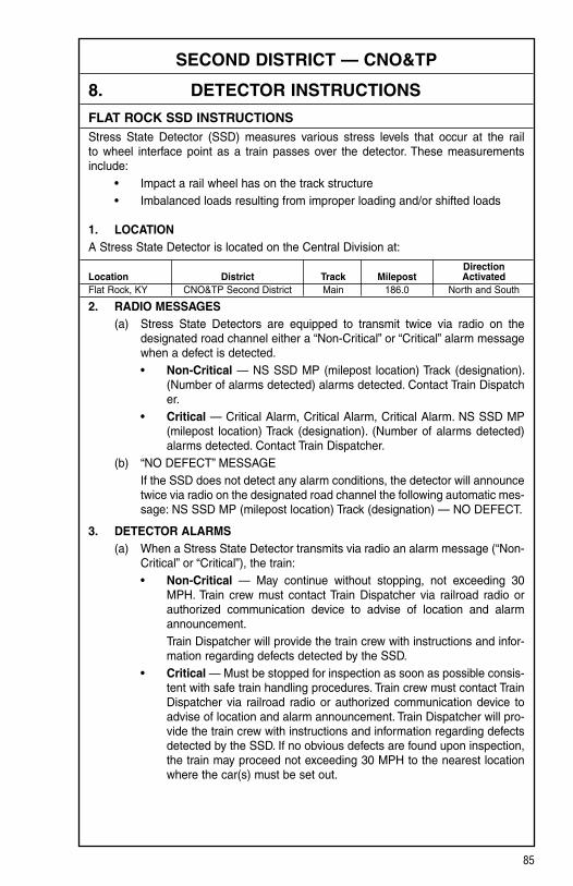
85
SECOND DISTRICT — CNO&TP
8. DETECTOR INSTRUCTIONS
FLAT ROCK SSD INSTRUCTIONSStress State Detector (SSD) measures various stress levels that occur at the rail to wheel interface point as a train passes over the detector. These measurements include: • Impact a rail wheel has on the track structure • Imbalanced loads resulting from improper loading and/or shifted loads
1. LOCATION A Stress State Detector is located on the Central Division at:
Direction Location District Track Milepost Activated Flat Rock, KY CNO&TP Second District Main 186.0 North and South
2. RADIO MESSAGES (a) Stress State Detectors are equipped to transmit twice via radio on the
designated road channel either a “Non-Critical” or “Critical” alarm message when a defect is detected.
• Non-Critical — NS SSD MP (milepost location) Track (designation). (Number of alarms detected) alarms detected. Contact Train Dispatcher.
• Critical — Critical Alarm, Critical Alarm, Critical Alarm. NS SSD MP (milepost location) Track (designation). (Number of alarms detected) alarms detected. Contact Train Dispatcher.
(b) “NO DEFECT” MESSAGE If the SSD does not detect any alarm conditions, the detector will announce
twice via radio on the designated road channel the following automatic mes-sage: NS SSD MP (milepost location) Track (designation) — NO DEFECT.
3. DETECTOR ALARMS (a) When a Stress State Detector transmits via radio an alarm message (“Non-
Critical” or “Critical”), the train: • Non-Critical — May continue without stopping, not exceeding 30
MPH. Train crew must contact Train Dispatcher via railroad radio or authorized communication device to advise of location and alarm announcement.
Train Dispatcher will provide the train crew with instructions and infor-mation regarding defects detected by the SSD.
• Critical — Must be stopped for inspection as soon as possible consis-tent with safe train handling procedures. Train crew must contact Train Dispatcher via railroad radio or authorized communication device to advise of location and alarm announcement. Train Dispatcher will pro-vide the train crew with instructions and information regarding defects detected by the SSD. If no obvious defects are found upon inspection, the train may proceed not exceeding 30 MPH to the nearest location where the car(s) must be set out.

86
SECOND DISTRICT — CNO&TP
8. DETECTOR INSTRUCTIONS (CONT.)
FLAT ROCK SSD INSTRUCTIONS (CONT.)3. DETECTOR ALARMS (CONT.) (b) If the SSD does NOT transmit a message or a message is NOT received,
the train must immediately reduce speed, not exceeding 30 MPH. Train crew must promptly contact Train Dispatcher via railroad radio or authorized com-munication device to advise of the location and failure of SSD announce-ment. Unless notified by the Train Dispatcher to stop and inspect a car(s), the train may then proceed at authorized speed without stopping.
The Train Dispatcher must promptly notify the C&S Department of the failure.
4. INSPECTION When notified by the Train Dispatcher to inspect a car(s), the train crew must
visually inspect the car(s) indicated. Based on the defect type, the following con-ditions should be inspected for:
(a) Wheel Impact • Flat spots/Shelled Tread • Broken/Cracked Wheel • Tread Build-up (b) Imbalanced Load • Bulging sides, doors, ends, or top chords • Leaning or listing • Springs that are completely compressed on one side and loose on the
other side • A restriction between the wheels and car body • Lading improperly distributed and/or shifted in open top cars
5. GENERAL INSTRUCTIONS Trains that stop on an SSD or do not maintain a minimum of 15 MPH while
passing over the SSD may receive multiple messages. When possible, stopping or reducing speed below 15 MPH should be avoided while passing an SSD. If multiple voice messages are received, the train crew must handle them as described in Section 2.
When an SSD announces any alarm, a crew member will promptly notify the Train Dispatcher of the alarm type.
When a car(s) must be inspected for SSD alarms, a crew member must provide the Train Dispatcher with the results of the inspection and furnish the following information:
• Train Identification • Car initial and number • Type of defect • Location of defect
The Train Dispatcher will determine proper disposition of car(s) based on any inspection result.

87
SECOND DISTRICT — CNO&TP
9. DISTRICT INSTRUCTIONS
A. EXCESSIVE CURVATURE Listed below are tracks with curvature of 12 degrees, 30 minutes or greater:
Milepost Location Curvature 158.5 Southern States 14.5 degrees158.8 General Electric 16.25 degrees160.0 Ready Mix Concrete 13.0 degrees162.0 Ferguson Lead 14.5 degrees163.5 Lake Cumberland Bldg. Auth. 13.5 degrees169.6 Kingsford Charcoal 14.25 degrees196.5 North Wye-Pine Knot 15.5 degrees196.6 South Wye-Pine Knot 14.0 degrees209.5 North Wye-Oneida 14.75 degrees209.5 South Wye-Oneida 13.25 degrees
Refer to the Equipment Restriction Section of the System Timetable.
B. SOMERSET Electric Switch Lock at MP 161.1, Track No. 2, CNO&TP District.Instructions for operation are shown below:
G&B Model 854 Electric Switch Lock: The locking mechanism locks the operating handle of the hand throw switch and is actuated by a foot pedal. The release of the locks is automatic for trains entering the switches from the Main Track.
1. For movement from Main Track to siding or spur track: (a) Stop engine or cars just ahead of switch points. (b) Remove padlock, actuate foot pedal to unlock position. This unlocks the
switch and it can be operated the same as any other hand throw switch.
2. For movement from siding or spur track to the Main Track: (a) Secure permission from the control station to operate the electric lock and
enter the Main Track. The switch must be unlocked and thrown before the derail or inside crossover switch is operated.
(b) Push down with hand on top latch for padlock and remove padlock. (c) Removal of padlock will put Main Track signals to stop and start time run-
ning. Immediately or after predetermined time interval has expired, the electric lock indicator will come on. Actuate foot pedal to unlock position. This unlocks the switch and it can be operated the same as any other hand throw switch. For movements using controlled electric locks, proceed as above after obtaining release from the control station.

88
SECOND DISTRICT — CNO&TP
9. DISTRICT INSTRUCTIONS (CONT.)
B. SOMERSET (CONT.)3. When movement over switch is completed, return handles and padlocks to
normal position.
An emergency release is located in the lock housing under the hinges for the top cover. The padlock must be removed before the cover for the emergency release can be raised. The emergency release is for use in case of trouble or if the electric lock fails to operate properly. Advise and secure authority from the control station to break the seal and rotate in a counter-clockwise direction to the 5 o’clock position. Switch may be lined and movement made when the emer-gency release is operated to enter Main Track from a spur track. If emergency release is operated, notify control station immediately as signals will remain in stop position until signal maintainer resets mechanism.
C. OAKDALE Crews taking charge of trains at Oakdale will receive their Train Clearance from the crew they are relieving or by other means. Conductors or Engineers will check order numbers with Train Dispatcher prior to leaving and must receive permission from the Train Dispatcher to depart.
D. STEARNS Empty and loaded auto racks are prohibited from all tracks in Stearns Yard, MP 190.0, including Revilo Lead, MP 192.0.
E. TRAIN HANDLING INSTRUCTIONS 1. Southward freight trains having a length in excess of 6,500 feet will be handled
by the following method between MP 146.0 and MP 148.0: Dynamic brake must be used to control train speed on descending grade. However, the dynamic brake must be released as locomotives ascend grade at MP 147.2 and throttle placed in No. 1 position until rear of train crests grade at MP 146.3 and slack is completely in.
After these conditions have been met, throttle may be advanced as necessary. These instructions do not apply to TV trains.
2. Northward radio trains will have throttle shut off and idle before passing MP 189.0. The dynamic brake will be applied to a minimum of 500 amps prior to the slack running out at MP 190.2.
These instructions do not apply when leaving Whitley after stopping, or if observing slow order between MP 191.0 and MP 188.0.
3. Southward freight trains having a length in excess of 6,500 feet will be handled by the following method between MP 230.0 and MP 233.0. As the locomotive con-sist crests grade at MP 230.0, throttle will be gradually reduced to throttle No. 1 as dictated by proper cresting of grade at MP 230.0 and slack is completely in. Dynamic brake may be used to control train speed, as necessary on descending grade; it must be released as locomotives ascend grade at MP 231.5, and throttle placed in No. 1 position until rear trains crests grade at MP 230.0 and slack is completely in. After these conditions have been met, throttle may be advanced as necessary. These instructions do not apply to TV trains.

89
SECOND DISTRICT — CNO&TP
9. DISTRICT INSTRUCTIONS (CONT.)
F. END-OF-TRAIN DEVICE — GRADESReference the identification of grades as required in NS-1 Rules for Equipment Operation and Handling, Rule A-31, End-Of-Train Device and revised NS-1 Rule L-241, to include instructions for descending grades of 1% or more.
In accordance with CFR Part 232, the following designated sections of track are identi-fied as average grades of:
2% or greater over a distance of 2 continuous miles or 1% or greater over a distance of 3 continuous miles:
SECOND DISTRICT CNO&TP
Northward Southward MP 139.3 to MP 135.0 = 1.00% MP 156.6 to MP 160.6 = 1.00% MP 179.8 to MP 169.8 = 1.00% MP 233.2 to MP 236.5 = 1.14% MP 207.6 to MP 203.6 = 1.00% MP 240.8 to MP 245.8 = 1.05%

90
THIRD DISTRICT — CNO&TP SOUTH SIDINGS IN FEET MP STATION NOTE
SOUTH END DISPATCHER .......................................
254.4 Oakdale ......................................................................... R
254.8 TUNNEL 25 ...................................................................
255.5 TUNNEL 26 ...................................................................
256.5 NORTH WATERS ..........................................................
257.8 SOUTH WATERS ..........................................................
258.2 HARRIMAN JCT. ..........................................................
259.7 NEW GRADE ................................................................
260.0 McCOY ..........................................................................
260.5 Emory Gap
261.4 E. G. TOWER .................................................................
261.9 HBD-DED-HWD (Emory Gap)
267.7 NORTH ROCKWOOD .................................................R
269.1 SOUTH ROCKWOOD ...................................................
270.8 HBD-DED (Rockwood)
275.4 NORTH RODDY ............................................................
277.3 SOUTH RODDY .............................................................
279.2 HBD-DED (Spring City)
283.2 NORTH SPRING CITY ................................................R
285.1 SOUTH SPRING CITY ..................................................
289.8 HBD-DED (Clear Creek)
292.2 NORTH EVENSVILLE ...................................................
295.0 SOUTH EVENSVILLE ...................................................
299.2 NORTH DAYTON .........................................................R
300.7 SOUTH DAYTON ...........................................................
302.7 HBD-DED (Dayton)
309.7 NORTH SALE CREEK ..................................................
311.8 SOUTH SALE CREEK ..................................................
312.6 HBD-DED (Bakewell)
319.6 HBD-DED (Daisy)
321.0 DAISY ..........................................................................R
325.0 CAVE SPRINGS ............................................................
327.1 HBD-DED (Hixson)
6200
7393
10082
9381
14186
7721
10550
D LINE
H LINE
EG LINE
H LINE
2 1 102
SS
CS
CS
CS
SS
CS
CS
CP
CP
CP
CP
CP
CP
CP
CP
CP
CP
CP
CP
CP
CP
CP
CP
CP
CP
CP
CP
CP
CP

91
THIRD DISTRICT — CNO&TP SOUTH SIDINGS IN FEET MP STATION NOTE
CT DISPATCHER .......................................................
328.7 HIXSON .........................................................................
331.3 TENBRIDGE .........................................................Y 1
331.7 BOYCE ........................................................................ Y
332.4 CITICO JCT. ............................................................... Y
334.6 DeButts Yard
338.0 Chattanooga ................................................................... R
STATION PAGE INFORMATIONNOTE 1: Chattanooga Terminal section governs between Tenbridge and Wauhatchie.
1. RULES IN EFFECT Main Main 1 Main 2 Track Track TrackBetween Rules Oakdale and Tunnel 25 261 261Tunnel 25 and Tunnel 26 261Tunnel 26 and E. G. Tower 261 261E. G. Tower and Daisy 261Daisy and Cave Springs 261 261Cave Springs and Hixson 261Hixson and Tenbridge 261 261
2 1 774
CP
CP
CP
CP
DB

92
THIRD DISTRICT — CNO&TP
2. MAXIMUM SPEEDS TV Frt.Between MPHMP 254.4, Oakdale and MP 331.2, Tenbridge 60 50 Except: MP 254.5, No. 2 Track over Switch with Engines Only 20 20 MP 254.4 to MP 254.8, Curves 25 25 MP 254.8, Through Turnout (No. 2 Track) Tunnel 25 20 20 MP 254.8 to MP 255.2, Curves 40 40 MP 255.2 to MP 255.5, Curves 50 50 MP 255.5, Through Turnout Tunnel 26 40 40 MP 256.5, Through Turnout North Waters 15 15 MP 257.8, Through Turnout South Waters 15 15 MP 257.8 to MP 258.2, Curves 40 40 MP 258.2, Through Turnout Harriman Jct. (to Knoxville) 20 20 MP 258.2, Through Crossover Harriman Jct. 25 25 MP 258.2 to MP 259.5, Curves 35 35 MP 259.5 to MP 260.6, Curves 45 45 MP 259.7 to MP 164.6H, Curves 15 15 MP 50.0d to MP 166.0H, Curves 15 15 MP 260.6 to MP 262.9, Curves 45 40 MP 261.4, Through Turnout E. G. Tower 40 40 MP 262.9 to MP 263.4, Curves 40 40 MP 264.6 to MP 265.0, Curves 55 50 MP 267.7 to MP 269.2, Through Turnouts and Rockwood Sdg. 20 20 MP 269.2 to MP 270.3, Curves 45 45 MP 273.7 to MP 274.0, Curves 50 50 MP 274.0 to MP 274.8, Curves 55 50 MP 275.4 to MP 277.4, Through Turnouts and Roddy Siding 20 20 MP 277.9 to MP 278.6, Curves 55 50 MP 278.6 to MP 278.9, Curves 50 45 MP 283.2 to MP 285.0, Through Turnouts and Spring City Sdg. 20 20 MP 286.9 to MP 288.0, Curves 50 50 MP 289.5 to MP 289.8, Curves 55 50 MP 290.5 to MP 290.7, Curves 50 45 MP 290.7 to MP 290.9, Curves 45 45 MP 291.6 to MP 292.2, Curves 55 50 MP 292.3 to MP 295.1, Through Turnouts and Evensville Sdg. 40 40 MP 297.5 to MP 300.6, Over Street Crossings Dayton 50 50 MP 299.2 to MP 300.7, Through Turnouts and Dayton Siding 20 20 MP 304.2 to MP 304.5, Curves 45 40 MP 304.5 to MP 304.9, Curves 45 45 MP 309.7 to MP 311.7, Through Turnouts and Sale Creek Sdg. 20 20 MP 310.9 to MP 311.4, Curves 50 45 MP 313.5 to MP 313.9, Curves 55 50 MP 314.5 to MP 314.8, Curves 55 50 MP 316.1 to MP 318.8, Curves 55 50 MP 319.1 to MP 323.3, Over Street Crossings Soddy Daisy 40 40 MP 321.0, Through Turnout Daisy 40 40

93
THIRD DISTRICT — CNO&TP
2. MAXIMUM SPEEDS (CONT.) TV Frt.Between MPH MP 321.0 to MP 322.7, Track No. 2 40 40 MP 322.5 to MP 322.7, Track No. 1, Curves 40 40 MP 322.7 to MP 323.7, Track No. 1, Curves 35 35 MP 322.7 to MP 323.7, Track No. 2 30 30 MP 323.7 to MP 325.0, Track No. 1, Curves 45 45 MP 323.7 to MP 325.1, Track No. 2 40 40 MP 325.0, Through Turnout Cave Springs 40 40 MP 325.0 to MP 325.4, Curves 45 45 MP 325.4 to MP 325.6, Curves 40 40 MP 325.6 to MP 326.0, Curves 40 35 MP 326.0 to MP 326.6, Curves 40 40 MP 326.6 to MP 327.4, Curves 35 35 MP 327.4 to MP 328.2, Curves 45 45 MP 328.2 to MP 328.4, Curves 45 40 MP 328.7, Through Turnout Hixson 40 40 MP 331.3, Through Crossovers Tenbridge 25 25
3. CHECKING LOCOMOTIVE SPEED INDICATORTests for accuracy will be made at the following locations and Engineers will adjust speed in accordance with any inaccuracy.
LOCATION OF TEST MILE SIGNS: SOUTHWARD NORTHWARD MP 257.0 to MP 258.0 MP 328.0 to MP 327.0 MP 263.0 to MP 264.0 MP 327.0 to MP 326.0 MP 270.0 to MP 271.0 MP 326.0 to MP 325.0
NOTE: Tests for accuracy will be made at other locations in addition to those shown. Engineers will choose appropriate locations to check speed indicators.
4. DIESEL UNIT RATINGS DIESEL UNIT RATINGS IN TONS Group 1 Group 2 Group 3 Group 4 Group 5 Group 6
SouthwardOakdale to Harriman Jct. 3200 4250 5100 6345 7050 8320 Harriman Jct. To Emory Gap 2550 3400 4050 5040 5600 6610 Emory Gap to DeButts 3100 4150 4950 6120 6800 8025
NorthwardDeButts to Oakdale 3200 4250 5100 6345 7050 8320

94
THIRD DISTRICT — CNO&TP
5. LOCOMOTIVE AND CAR RESTRICTIONS
A. WEIGHT RESTRICTIONSLoaded 4-axle cars may be handled up to the weight shown provided the stenciled Load Limit (Weight of car and lading) is NOT exceeded. 286,000 lbs.
B. EQUIPMENT RESTRICTIONSTrailing tonnage must be limited on line segments as shown below, behind the following equipment:1. Empty Multi-level cars.2. Empty Intermodal single-platform flats and such loaded with empty trailers or
containers.3. Empty 85-foot-long or longer flats and such flat cars when loaded with empty
trailers or containers, or loaded with only one (1) trailer or container.4. Empty Intermodal single-axle truck flat car or such cars loaded with empty
trailers or containers.5. Empty single or multiple-unit double-stack (well) cars, or articulated single-
platform (spine) cars. Be governed by Appendix 1 in the System Timetable.
Maximum Safe Trailing Tonnage Southward/ Northward/ Line Segments Between Westward EastwardThird District Oakdale and Chattanooga 12,000 14,200
C. 6-AXLE DIESEL UNITS These restrictions do not apply to Main Track.
6-axle locomotives may operate over the following tracks at a speed not to exceed 5 MPH: MP 298.4 — Polyloom-Dayton MP 309.8 — Runaround Track-Sale Creek
D. TRAILING TONNAGE RESTRICTIONS —RAILRUNNER* EQUIPMENT Maximum Safe Trailing Tonnage Empty Loaded Less than Light Load 28 Tons Line Segments Between 18 Tons 18–27 Tons or MoreThird District CNO&TP Oakdale and Chattanooga 4,400 4,400 5,200 (Jersey)NOTE: *RailRunner Block MUST TRAIL RoadRailers.

95
THIRD DISTRICT — CNO&TP
6. SWITCHES AND DERAILS
A. JUNCTIONS INTERLOCKED
Milepost Location Line/R.R. 258.2 Harriman Jct. Oakdale Line 259.7 New Grade H Line 260.0 McCoy EG Line
NON-INTERLOCKEDMilepost Location Line/R.R. 260.5 Emory Gap H Line
B. SWITCHES
Main Track switches not equipped with electric locks: MP 254.5 — Oakdale Yard South End Lead
Main Track switches not equipped with electric locks must not at any time be used to clear Main Line. No trains or engines shall clear the Main Line at any of these tracks. While using such tracks, an engine or car must continuously occupy the Main Track or Main Track switch must be continuously set for movement into such track.
C. EMORY GAP, TNTVA #1 track at Emory Gap, TN., is equipped with locks, and the normal position for the switches for TVA #1 is aligned and locked for movement on TVA #1 is considered the running track to and from TVA Kingston and is to be kept clear of any unattended equipment.
7. COMMUNICATION INFORMATION Channel 1 Channel 2 Base Station TX and RX TX (RX)Oakdale 56 48 (9)Rockwood 56 48 (9)Spring City 56 48 (9)Dayton 56 48 (9)Daisy 56 48 (9)
8. DETECTOR INSTRUCTIONSNone.

96
THIRD DISTRICT — CNO&TP
9. DISTRICT INSTRUCTIONS
A. EXCESSIVE CURVATURE Listed below are tracks with curvature of 12 degrees, 30 minutes or greater:
Milepost Location Curvature 298.4 Polyloom 17.0 degrees331.2 South Leg of Wye-Tenbridge 14.0 degreesRefer to the Equipment Restriction Section of the System Timetable.
B. OAKDALE Crews taking charge of trains at Oakdale will receive their Train Clearance from the crew they are relieving or by other means. Conductors or Engineers will check order numbers with Train Dispatcher prior to leaving Oakdale and must receive permission from the Train Dispatcher to depart. Northward trains must not pass North Oakdale prior to receiving permission from Train Dispatcher to depart Oakdale.
C. DAYTON, TNThe following switching instructions are in effect at Polyloom, MP 298.4: Cars must have hand brakes released, air cut in and automatic brake released
while shoving on Polyloom Lead. The air brake may be used only when spotting cars inside the building, not while shoving up hill from the Main Line on the Lead to the building.
The alarm near the mailbox at Polyloom entrance will be activated to warn Polyloom employees of movement prior to entering the building.
Crossing bells and lights have been installed on the Lead at the Road Crossing at TC Thiolon (Polyloom) in Dayton, TN, MP 298.4. There is a lock box approxi-mately 30 feet from the crossing on the south side of the track that is equipped with an NS Switch Lock. To activate lights and bells, open lock box and push Green button. Upon completion of switching, push and hold Red button until deactivation of lights and bells. Close and lock box before departing.
D. END-OF-TRAIN DEVICE — GRADESReference the identification of grades as required in NS-1 Rules for Equipment Operation and Handling, Rule A-31, End-Of-Train Device and revised NS-1 Rule L-241, to include instructions for descending grades of 1% or more.
In accordance with CFR Part 232, the following designated sections of track are identi-fied as average grades of:
2% or greater over a distance of 2 continuous miles or 1% or greater over a distance of 3 continuous miles:
THIRD DISTRICT CNO&TP
Northward Southward None None

97
104
LOUISVILLE DISTRICT EAST SIDINGS IN FEET MP STATION NOTE
LOUISVILLE DISPATCHER ........................................
268.3 W TATEM ........................................................................... 2
268.9 W K&I JCT. ................................................................ 1
269.9 W IN/KY State Line
270.2 W DI TOWER ......................................................................
270.4 W Louisville .....................................................................R, Y
270.4 W PORTLAND AVE. .........................................................
271.6 W MADISON ST. ................................................................
272.3 W GARLAND AVE. ............................................................
272.8 W VIRGINIA AVE. ..............................................................
274.8 W FOURTEENTH ST. ...................................................
274.9 W LS JCT. .................................................................. 1, 2
276.2 W FOURTH STREET .........................................................
276.2 W FOURTH STREET ...........................................................
276.7 W FLOYD STREET ..............................................................
278.2 W PRESTONIA .................................................................
279.6 W DUMESNIL ....................................................................
280.9 W Whitner ........................................................................... R
282.5 W Appliance Park
283.0 W Buechel
286.1 W HBD-DED (Jeffersontown)
287.2 W Jeffersontown
2 1
CSXT
PAL
CSXT
CSXT
6934
CPYL
CP
CS
CP
CP
CP
CP
CP
CP
CPYL
CP
CP
CP

98
LOUISVILLE DISTRICT EAST SIDINGS IN FEET MP STATION NOTE
LOUISVILLE DISPATCHER ........................................
287.7 W Bluegrass
289.0 W Tucker
293.4 W HBD-DED-HWD (Fisherville)
293.8 W Fisherville
300.7 W Veechdale ....................................................................... R
301.2 W HBD-DED (Veechdale)
302.1 W MANETTA ......................................................................
305.0 W Joyes
307.2 W SHELBYVILLE ................................................................ 3
312.4 W HBD (Hooper Station)
319.0 W Waddy
323.0 W HBD-DED (Avenstoke)
327.0 W Alton ............................................................................... R
329.5 W Coal Chute
331.0 W Lawrenceburg
335.4 W McBrayer
337.5 W HBD (Nevin)
342.3 W WEST TALMAGE ...........................................................
344.3 W EAST TALMAGE ...........................................................
348.4 W HBD-DED (Harrodsburg)
352.5 W HARRODSBURG ........................................................R
356.8 W S. WYE ...........................................................................
NORTH END DISPATCHER ........................................
357.8 W S.J. TOWER ................................................................. Y
4
STATION PAGE INFORMATIONNOTE 1: Permission must be received from Louisville Train Dispatcher before entering yard
limits between K&I Jct. and LS Jct. Except: Does not apply to trains entering yard limits on signal indication.
NOTE 2: Louisville Terminal section governs between LS Jct and Tatem. NOTE 3: Gate operation instructions for RJ Corman Interlocking, MP 307.2 W are posted in
box at location. NOTE 4: Danville Terminal section governs between Faulkner and South Danville.
10472
9998
11632
10266
10426
SJ TOWER N. WYE
104
CS
CP
103
CP
CP
CP
CP
CP

99
LOUISVILLE DISTRICT
1. RULES IN EFFECT Main Main 1 Main 2 Track Track TrackBetween Rules Tatem and K&I Jct. 261 261K&I Jct. and DI Tower 93 93DI Tower and DI Tower 261 261DI Tower and Portland Ave. 93 93Portland Ave. and Portland Ave. 261 261Portland Ave. and Madison St. 93 93Madison St. and Madison St. 261 261Madison St. and Garland Ave. 93 93Garland Ave. and Garland Ave. 261 261Garland Ave. and Virginia Ave. 93 93Virginia Ave. and Virginia Ave. 261 261Virginia Ave. and Fourteenth St. 93 93Fourteenth St. and Fourteenth St. 261 261Fourteenth St. and LS Jct. 93 93LS Jct. and Fourth St. 261 261Fourth St. and Dumesnil 261Dumesnil and Manetta 271Manetta and Manetta 261Manetta and West Talmage 271West Talmage and S.J. Tower 261 261S.J. Tower and DV Tower 261 261DV Tower and Danville 261 261
2. MAXIMUM SPEEDS Main TracksBetween MPHMP 268.3 W and MP 275.2 W 15 Except: MP 268.7 W to MP 269.0 W, Curves 10 MP 274.9 W, LS Jct., Through CSXT Seventh to Magnolia Connection Track 15 MP 275.2 W and MP 277.4 W 20MP 277.4 W and MP 357.8 W 45 Except: MP 278.0 W to MP 279.6 W, Curves 35 MP 284.9 W to MP 287.7 W, Curves 40 MP 287.7 W to MP 292.7 W, Curves 35 MP 292.7 W to MP 299.8 W, Curves 40 MP 299.8 W to MP 303.1 W, Curves 35 MP 303.1 W to MP 307.1 W, Curves 40 MP 307.2 W, RJCC Crossing 35 MP 307.5 W to MP 308.1 W, Curves 35 MP 308.1 W to MP 308.6 W, Curves 30 MP 308.6 W to MP 324.2 W, Curves 35 MP 311.6 W to MP 312.0 W West end Guist Creek Trestle 35 (Except Radio Controlled Grain trains with 6 units or less) 25 MP 318.0 W, Through Turnout Waddy Siding 20 MP 318.0 W to MP 320.3 W, Through Waddy Siding 20 MP 320.3 W, Through Turnout, Waddy Siding 20 MP 324.2 W to MP 328.3 W, Curves 40 MP 327.3 W to MP 350.6 W, Radio Controlled Trains 30 MP 328.3 W to MP 328.6 W, Curves 35

100
LOUISVILLE DISTRICT
2. MAXIMUM SPEEDS (CONT.) MP 328.6 W to MP 338.9 W, Curves 40 MP 338.9 W to MP 341.3 W, Curves 35 MP 341.3 W to MP 350.4 W, Curves 40 MP 350.4 W to MP 350.8 W, Curves 35 MP 350.8 W to MP 351.1 W, Curves 25 MP 351.1 W to MP 351.4 W, Curves 20 MP 351.4 W to MP 351.5 W, Curves 15 MP 351.5 W to MP 351.8 W, Curves 20 MP 351.8 W to MP 352.6 W, Curves 25 MP 352.6 W to MP 353.1 W, Curves 40 MP 353.1 W to MP 357.6 W, Curves 45Auxiliary Track: Extension track between Woods Track switch and Old Sheperdsville Road Mixing Center Speeds: 15 Ramp Track (RP01-RP07) — Restricted Speed not exceeding 5 All tracks from switch Manetta to North Lead switch are Restricted Speed not exceeding 15
3. CHECKING LOCOMOTIVE SPEED INDICATORTests for accuracy will be made at the following locations and Engineers will adjust speed in accordance with any inaccuracy.
LOCATION OF TEST MILE SIGNS: EASTWARD WESTWARD MP 278.0 W to MP 279.0 W MP 357.0 W to MP 356.0 W MP 279.0 W to MP 280.0 W MP 281.0 W to MP 282.0 W MP 283.0 W to MP 284.0 W MP 291.0 W to MP 292.0 W MP 293.0 W to MP 294.0 W MP 315.0 W to MP 316.0 W MP 329.0 W to MP 330.0 W MP 333.0 W to MP 334.0 W
NOTE: Tests for accuracy will be made at other locations in addition to those shown. Engineers will choose appropriate locations to check speed indicators.
4. DIESEL UNIT RATINGS DIESEL UNIT RATINGS IN TONS Group 1 Group 2 Group 3 Group 4 Group 5 Group 6
EastwardLouisville to Lawrenceburg 1650 2200 2650 3320 3600 4250 Lawrenceburg to Danville 2750 3650 4400 5445 6050 7140
WestwardDanville to Lawrenceburg 2600 3450 4150 5130 5700 6725 Lawrenceburg to Louisville 1750 2350 2800 3465 3850 4540

101
LOUISVILLE DISTRICT
5. LOCOMOTIVE AND CAR RESTRICTIONS
A. WEIGHT RESTRICTIONSLoaded 4-axle cars may be handled up to the weight shown provided the stenciled Load Limit (Weight of car and lading) is NOT exceeded. 286,000 lbs.
B. 6-AXLE DIESEL UNITS 6-axle engines may operate over the following tracks at a speed not to exceed 5 MPH: MP 282.5 W — Appliance Park Yard Tracks, Wye
C. EQUIPMENT RESTRICTIONSTrailing tonnage must be limited on line segments as shown below, behind the following equipment:1. Empty Multi-level cars.2. Empty Intermodal single-platform flats and such loaded with empty trailers or
containers.3. Empty 85-foot-long or longer flats and such flat cars when loaded with empty
trailers or containers, or loaded with only one (1) trailer or container.4. Empty Intermodal single-axle truck flat car or such cars loaded with empty
trailers or containers.5. Empty single or multiple-unit double-stack (well) cars, or articulated single-
platform (spine) cars. Be governed by Appendix 1 in the System Timetable.
Maximum Safe Trailing Tonnage Southward/ Northward/ Line Segments Between Westward EastwardLouisville Louisville and Danville 7,800 6,400**EXCEPT: 5,600 tons behind empty TTOX flat cars.
6. SWITCHES AND DERAILS
SPRING SWITCHESSpring switches are located as follows:Milepost Location Normal Position 288.0 W West End, Tucker Siding Main Track290.0 W East End, Tucker Siding Main Track303.9 W West End, Joyes Siding Main Track305.9 W East End, Joyes Siding Main Track318.0 W West End, Waddy Siding Main Track320.3 W East End, Waddy Siding Main Track328.6 W West End, Coal Chute Siding Main Track330.6 W East End, Coal Chute Siding Main Track

102
LOUISVILLE DISTRICT
5. LOCOMOTIVE AND CAR RESTRICTIONS (CONT.)
7. COMMUNICATION INFORMATION Channel 1 Channel 2 Base Station TX and RX TX (RX)Louisville East 56 48 (9)Veechdale 56 48 (9)Alton 56 48 (9)Harrodsburg 56 48 (9)
8. DETECTOR INSTRUCTIONSNone.
9. DISTRICT INSTRUCTIONS
A. RAILROAD CROSSING AT GRADE
INTERLOCKEDMilepost Location Line/R.R. 276.2 W Fourth Street (Note 1) CSXT R. R.276.7 W Floyd Street CSXT R. R.
NON-INTERLOCKEDMilepost Location Line/R.R. 307.2 W Shelbyville, KY RJ Corman, R.R.NOTE 1: FOURTH STREET, LOUISVILLE, KY, CSXT Railroad Crossing, MP 276.2 W: When operating on NS tracks, all interlocking home signals are approach cleared
with supervisory control by Louisville District Dispatcher, to hold trains at the point when necessary. Train or engine crews should contact Louisville District Dispatcher by radio when they receive a “STOP” indication in either direction, to secure permis-sion to operate push button release.
The following are detailed instructions for operation of emergency release. “PUSH BUTTON” is located above push button box on signal bungalow. (a) Must have authorization from Louisville District Dispatcher, to operate push
button release. (b) Open push button box marked “NS” on east side of signal bungalow. (c) Green indicator light in box will be illuminated if CSXT signals indicate stop.
The button marked “CLEAR” may be pushed immediately if Green indication is illuminated.
(d) If indicator is not illuminated, check all CSXT tracks for approaching trains or engines.
(e) Push button may now be operated only if no CSXT engines or trains are approaching crossing.
(f) After four (4) minutes have elapsed, if NS signal does not clear, movement may be made in accordance with Rule 238(b).

103
LOUISVILLE DISTRICT
9. DISTRICT INSTRUCTIONS (CONT.)
B. TRAIN HANDLING INSTRUCTIONS The following instructions will apply for trains operating between Louisville and Danville: When westward trains are required to stop at the west switch at Tucker,
MP 288 W, a 10 PSI brake pipe reduction is required, instead of a full service brake pipe reduction.
C. WAITING TIMESAt the following locations, waiting times shown must be observed:Milepost Location Time287.6 W West End Bluegrass 8 minutes 293.9 W Fisherville 10 minutes 300.6 W Veechdale 10 minutes
D. PASSING TIMESWhen necessary for a train to pass another train standing on the Main Track, push-button devices will be activated on bungalow at locations with waiting period as listed:Milepost Location Time288.0 W West End, Tucker Siding 8 minutes 290.0 W East End, Tucker Siding 5 minutes 303.9 W West End, Joyes Siding 6 minutes 305.9 W East End, Joyes Siding 8 minutes 318.0 W West End, Waddy Springs 6 minutes 320.3 W East End, Waddy Springs 7 minutes 328.6 W West End, Coal Chute Siding 8 minutes 330.6 W East End, Coal Chute Siding 5 minutes
E. CLOSE CLEARANCE Close clearance condition exists on the south side of the No. 1 Main Line between MP 275.3 W and MP 275.8 W, Louisville. Employees are prohibited from riding the side or end of equipment at this location.
F. CSXT EN ROUTE TO NSAll northward trains departing CSXT en route to the NS will need: 1. Signal indication, and 2. Verbal permission from NS Louisville Train Dispatcher prior to passing the CSXT
Northward-signal governing movement onto the NS connection track at 7th Street and Magnolia.
G. CSXT OSBORNE YARD, LOUISVILLEAll crews operating into CSXT Osborne Yard, Louisville, will be governed by the fol-lowing instructions for properly securing equipment left standing in any track: One (1) car — one (1) hand brake; two (2) cars — two (2) hand brakes; three (3)
cars — three (3) hand brakes. More than three (3) cars must be secured with a minimum of three (3) hand brakes.

104
LOUISVILLE DISTRICT
9. DISTRICT INSTRUCTIONS (CONT.)
H. PRESTONIA All westward trains that are not lined by Prestonia must stop short of the golf course clubhouse area until further instructions are received to pull train all the way to the West End. This is to be done to reduce having idling locomotives parked behind the houses on the north side of the tracks. Take care not to stop too far east of this point as doing so will create the same problem for residents on the south side of the tracks. Trains that must pull all the way to the west end that are going to be stopped for 45 minutes or more must shut down all the engines in the consist, temperature permitting. If it is not known how long the delay will be and the Train Dispatcher or Louisville Tower cannot be reached, shut down the engines.
I. WHITNER When shoving or pulling cars across Produce Road (Whitner, KY, MP 281.3 W) between sunset and sunrise, a member of the crew must be stationed on both sides of movement at crossing, and displaying lighted fusees until entire movement has cleared the crossing.
In the event two (2) employees cannot protect both sides of crossing, burning fusees will be placed on one side of crossing and crew member will protect the other side, until the movement completely clears the crossing. These instructions do not apply to grade crossing with automatic warning devices.
Whitner Intermodal tracks IM01 and IM02 have been painted with Orange paint for a distance of 25 feet from the wheel stops. No cars will be spotted in the painted area. When shoving cars on any yard track at Whitner and Appliance Park (except for the Extension Track and the Siding), the maximum authorized speed will be 5 MPH.
J. BUECHEL When Buechel locals are assisting through trains in picking up and setting out at Whitner/Buechel, switching moves on opposite ends of trains must not be made simul-taneously. One (1) move must be stopped and crew members in clear of train before switching moves are made on opposite end of train. For safety reasons, switching moves must not be made on opposite end of trains simultaneously. Good communica-tions between crews is necessary to prevent injuries/accidents.
K. APPLIANCE PARK The following instructions govern the entrance into the GE facility at Appliance Park, Louisville District, MP 282.2.
GE at Appliance Park has installed security gates at their facility. Crews needing to gain access will contact GEA security at 502-452-4666 (who will handle the opening of the gate). Crews that will perform switching at GE must first notify GEA security in advance of arrival to perform switching. Notification will be done by company cell phone or through CYO. GEA security will close gate behind crews until switching is complete and only reopen upon the request of the crew for departure.
L. TUCKER All trains or equipment left unattended at Tucker, MP 289.7 W must be secured with a minimum of 10 hand brakes in addition to securing the locomotives.

105
LOUISVILLE DISTRICT
9. DISTRICT INSTRUCTIONS (CONT.)
M. MIXING CENTER INSTRUCTIONS NS trains must receive permission from the Mixing Center to enter the Limits of the Shelbyville Mixing Center, MP 302.2 W to MP 304.9 W. The Limits include the Mixing Center’s Yard Tracks, East and West Leads. NS personnel cannot foul these limits without first receiving proper permission from the Mixing Center. The Upper Crossover on the East End of the Shelbyville Mixing Center is equipped with NS switch locks. After used, the crossover must be lined and locked for normal position (normal posi-tion is lined for straight track). In addition to all NS Operating and Safety Rules, NS crews, while operating within the Shelbyville Mixing Center, will be governed by the instructions and procedures provided by the Mixing Center and listed below.
Eastward trains with a set-out or pickup for the Shelbyville Mixing Center, must contact the Mixing Center before passing the control point at Manetta, MP 302.2 W and be governed by instructions received. If the train has to head in at the West Lead, the train must contact the Louisville District Dispatcher and request a signal to enter the West Lead by way of the power switch at Manetta. Westward trains with a set-out or pick-up for the Shelbyville Mixing Center must contact the Mixing Center before passing the East End of Joyes Siding, MP 305.9 W and be governed by instructions received.
DEPARTING:1. Train must contact the Shelbyville Mixing Center for movement(s) within the
facility.2. Obtain proper permission from the Louisville District Dispatcher for departure to
Main Line or siding.3. Report to the Shelbyville Mixing Center when train is clear of Mixing Center track
limits.
OTHER MOVEMENTS:All trains must receive permission from the Mixing Center before fouling any track within the facility or to pass from one (1) track to another through a crossover. Crews must always report to the Mixing Center when they have cleared the Mixing Center limits and switches have been returned to the normal position. All Norfolk Southern crews working at Shelbyville Mixing Center will identify on the radio the position of crossover switches to be used in their movement. Example: Both switches of lower crossover are in correspondence and lined for straight track or both switches of lower crossover are in correspondence and lined for the crossover. These instructions apply to all movements over crossover switches, either when moving on straight track or when moving through crossover.
DERAILS: There are four (4) derails within the facility:1. A power derail located on the West end of the West Lead at MP 302.2 W. 2. A hand-operated derail located just west of the West Lead of the Support and
Ramp Yards. The derail will be lined and locked in the derailing position with a contractor’s lock. NS crews will contact the Mixing Center for removal of derail and permission to use the West Lead. Mixing Center contractor will be respon-sible for removal and restoration of the derail.
3. A hand-operated derail located on the east end of the South Lead that connects to the Joyes Siding.
4. A hand-operated derail located on the North Lead just west of the switch to Joyes Siding.

106
LOUISVILLE DISTRICT
9. DISTRICT INSTRUCTIONS (CONT.)
M. MIXING CENTER INSTRUCTIONS (CONT.)HAND BRAKES1. Sufficient number of hand brakes must always be applied to secure standing
equipment. No single railcar may be left standing in the Support Yard or Ramp Yard (unattended) unless coupled to another rail car and both are properly secured with hand brakes. When two (2) or more cars are left standing, a minimum of two (2) hand brakes must be applied or 10% of the total cars, which ever is greater.
Example: 30 cars — a minimum of three (3) brakes. 35 cars — a minimum of four (4) brakes.
Follow the guidelines set forth and apply additional hand brakes as needed to adequately secure the equipment.
2. The following instructions govern the movement of NS trains over the Upper Crossover, No. 2 and No. 3 Crossovers on the East End of the Shelbyville Mixing Center. These instructions do not change the Central Division Operations Bulletins governing movements within the Mixing Center. Permission to foul the South Lead through these crossovers will be handled between the Mixing Center Rail Coordinator and the NS Conductor or utility person. The same PERSON that is granted the permission to use these crossovers will be the one giving up this authority once they know that their movement has cleared and the switches are lined back for the South Lead.
(a) NS Train Conductor or utility person will identify themselves and the train that will use the crossover. Crossover(s) will not be lined until permission is granted.
(b) After the NS movement has cleared the South Lead and all switches are lined and locked back for the South Lead the Conductor or utility person who received the permission will:
1. Advise the Rail Coordinator, “No. 2 and No. 3 CROSSOVERS ARE LINED AND LOCKED FOR THE SOUTH LEAD, TRAIN No.______ IS CLEAR OF THE SOUTH LEAD”. If clearing the Upper Crossover, “THE UPPER CROSSOVER IS LINED AND LOCKED FOR THE SOUTH LEAD, TRAIN No. ________ IS CLEAR OF THE SOUTH LEAD”.
2. The Rail Coordinator will repeat this information back to the NS Conductor/utility person who will confirm by repeating again as stated above.

107
LOUISVILLE DISTRICT
9. DISTRICT INSTRUCTIONS (CONT.)
N. JOYES The normal position for Aaper Chemical Company switch is lined for LEDCO Lead.
Except where further restricted, eastward trains or engines operated at less than 25 MPH between the east end siding Joyes, MP 305.9 W and the CSXT Interlocking, MP 307.2 W, and westward trains or engines operated at less than 25 MPH between the positive signal located at MP 309.3 W and the CSXT Interlocking, MP 307.2 W must approach the CSXT Interlocking, MP 307.2 W prepared to stop until it is plainly seen that the Interlocking is not fouled.
O. SHELBYVILLE ASPHALT INDUSTRYInstructions for Shelbyville Asphalt Industry, MP 306.2 W:
1. Close clearance restrictions are in effect for the north side of Track No. 1 and the south side of Track No. 2 at Shelbyville Asphalt, MP 306.2 W due to the unloading pipe rack located between the tracks.
2. No cars are to be spotted within 50 feet of earth mounds.
3. 100% hand brakes are required for up to three (3) cars on both tracks. A minimum of three (3) hand brakes is required for three (3) or more cars on both tracks.
P. CORMAN INTERLOCKING, MP 307.2 WGate operation instructions for Corman Interlocking, MP 307.2 W are posted in box at location.
In addition to posted instructions: R.J. Corman Train Crews must contact Louisville Dispatcher and obtain permis-
sion to activate timer lever on signal Bungalow to ensure no approaching move-ments are in the vicinity. Once permission is granted, be governed by posted instructions at this location in the event radio communication fails.
Q. LAWRENCEBURG 1. The switch connecting the west leg of Wye and east leg of Wye, located at
Lawrenceburg, KY, will be lined and locked for movement on the east leg of Wye.
2. Close clearance exists between the New Track and New Spur tracks in Lawrenceburg, KY, MP 331.5 W. Close clearance is account tracks are close together and an employee cannot ride between tracks.
R. TRESTLES All trains and engines will sound warning whistle approaching the following trestles at which whistle posts have been erected: Floyds Fork Creek — MP 294.0 W Pope Lick — MP 292.5 W

108
LOUISVILLE DISTRICT
9. DISTRICT INSTRUCTIONS (CONT.)
S. END-OF-TRAIN DEVICE — GRADESReference the identification of grades as required in NS-1 Rules for Equipment Operation and Handling, Rule A-31, End-Of-Train Device and revised NS-1 Rule L-241, to include instructions for descending grades of 1% or more.
In accordance with CFR Part 232, the following designated sections of track are identi-fied as average grades of:
2% or greater over a distance of 2 continuous miles or 1% or greater over a distance of 3 continuous miles:
LOUISVILLE DISTRICT
Eastward Westward MP 290.0 W to MP 293.0 W = 1.17% MP 286.5 W to MP 283.5 W = 1.13% MP 298.3 W to MP 294.0 W = 1.00%

109
CINCINNATI DISTRICT EAST SIDINGS IN FEET MP STATION NOTE
NEW CASTLE DISTRICT DISPATCHER ....................
CV 111.9 VALLEY .........................................................................
NORTH END DISPATCHER ........................................
CV 110.7 RED BANK ....................................................................
CT 9.0 CLARE ...........................................................................
CT 11.1 NEWTOWN ....................................................................
CT 12.2 W. ANCOR .....................................................................
CT 13.7 E. ANCOR .....................................................................
CT 20.9 SAD (Gernon, OH)
CT 23.0 W. BATAVIA ...................................................................
CT 24.0 E. BATAVIA ....................................................................
CT 30.5 W. AFTON ......................................................................
CT 31.9 E. AFTON ......................................................................
CT 33.0 SAD (Williamsburg, OH)
CT 45.3 SAD (White Oak, OH)
CT 46.8 HOS SARDINA ..............................................................
CT 47.7 W. SARDINA .................................................................
CT 49.0 E. SARDINA ..................................................................
CT 57.7 SAD (Winchester, OH)
CT 59.2 W. MT. ZION ..................................................................
CT 60.5 E. MT. ZION ...................................................................
CT 67.0 W. LAWSHE ...................................................................
CT 68.2 E. LAWSHE ...................................................................
CT 72.0 SAD (Peebles, OH)
CT 82.1 W. RARDEN ..................................................................
CT 83.3 E. RARDEN ...................................................................
CT 85.2 SAD (Youngs, OH)
CT 92.7 W. BROOKSIDE ............................................................
CT 94.1 E. BROOKSIDE .............................................................
CT 97.9 SAD (McDermott, OH)
CT 105.0 VERA .............................................................................
6847
3926
5962
5905
5990
6053
5588
6090
2 1
CP
399
103
CP
CP
CP
CP
CP
CP
CP
CP
CP
CP
CP
CP
CP
CP
CP
CP
CP
CP
CP
CP
CP

110
CINCINNATI DISTRICT
1. RULES IN EFFECT Main Main 1 Main 2 Track Track TrackBetween RulesValley and Clare 261 261 261Clare and Vera 171 171 171
2. MAXIMUM SPEEDS Main TracksBetween MPHMP CV 111.9, Valley and MP CT 73.5 25 Except: MP CT 8.8 to MP CT 9.3, Through Curves and Bridge 10 MP CT 12.2 to MP CT 13.7, Through Turnouts and Siding 10 MP CT 23.0 to MP CT 24.0, Through Turnouts and Siding 10 MP CT 30.5 to MP CT 30.9, Through Turnouts and Siding 10 MP CT 47.9 to MP CT 49.0, Through Turnouts and Siding 10 MP CT 59.2 to MP CT 60.5, Through Turnouts and Siding 10 MP CT 67.0 to MP CT 68.2, Through Turnouts and Siding 10 MP CT 82.1 to MP CT 83.3, Through Turnouts and Siding 10 MP CT 89.1 to MP CT 89.5, Curve 35 MP CT 91.9 to MP CT 92.5, Curve 30 MP CT 92.5 to MP CT 92.7 35 MP CT 92.7 to MP CT 94.1, Through Turnouts and Siding 10 MP CT 92.7 to MP CT 94.1 35 MP CT 94.1 to MP CT 94.3, Curve 30 MP CT 94.3 to MP CT 96.1 35 MP CT 96.1 to MP CT 96.4, Curve 30 MP CT 96.4 to MP CT 99.0 35 MP CT 99.0 to MP CT 99.3, Curve 30 MP CT 99.3 to MP CT 104.4 35 MP CT 104.4 to MP CT 105.0, Curve 25 MP CT 104.5 to MP CT 104.9, Bridge, Double-stack Cars Only 10 MP CT 105.0, Through Turnout 25NOTE: MP CT 73.5 — MP CT 105.0, Vera is out of service.
3. CHECKING LOCOMOTIVE SPEED INDICATORTests for accuracy will be made at the following locations and Engineers will adjust speed in accordance with any inaccuracy.
LOCATION OF TEST MILE SIGNS: MP CT 14.55 to MP CT 15.55

111
CINCINNATI DISTRICT
4. DIESEL UNIT RATINGS DIESEL UNIT RATINGS IN TONS Group 1 Group 2 Group 3 Group 4 Group 5 Group 6
WestwardPortsmouth to Cincinnati 1600 2150 2550 3150 3500 4130
EastwardCincinnati to Lawshe 1900 2550 3050 3735 4150 4900Lawshe to Portsmouth 1500 2000 2400 2970 3300 3890
5. LOCOMOTIVE AND CAR RESTRICTIONS
A. WEIGHT RESTRICTIONSLoaded 4-axle cars may be handled up to the weight shown provided the stenciled Load Limit (Weight of car and lading) is NOT exceeded. 291,000 lbs.
6-axle unit prohibited: MP CT 47.6 — Mowrystown Branch
B. EQUIPMENT RESTRICTIONSTrailing tonnage must be limited on line segments as shown below, behind the following equipment:1. Empty Multi-level cars.2. Empty Intermodal single-platform flats and such loaded with empty trailers or
containers.3. Empty 85-foot-long or longer flats and such flat cars when loaded with empty
trailers or containers, or loaded with only one (1) trailer or container.4. Empty Intermodal single-axle truck flat car or such cars loaded with empty
trailers or containers.5. Empty single or multiple-unit double-stack (well) cars, or articulated single-
platform (spine) cars. Be governed by Appendix 1 in the System Timetable.
Maximum Safe Trailing Tonnage Southward/ Northward/ Line Segments Between Westward EastwardCincinnati District Clare and Batavia 8,000 8,000 Batavia and Portsmouth 5,000 5,000
Any district or segment not listed is restricted to trailing tonnage not exceeding 14,000 tons.These instructions do not apply to radio trains.
C. HEIGHT RESTRICTIONSMP CT 104.5, Vera, Bridge, double-stack cars exceeding 19'3" are not permitted.

112
CINCINNATI DISTRICT
6. SWITCHES AND DERAILSNone.
7. COMMUNICATION INFORMATIONRADIOEmergency Code 911 CYO Code 108 North End Dispatcher AAR CH 56-48 (9) Code 774 New Castle Dispatcher AAR CH 22-22 Code 399 Chicago District Dispatcher AAR CH 92-92 Code 922 CSXT “CK” Dispatcher AAR CH 66-66 Code 1 CSXT Road AAR CH 08-08 Gest Street Yardmaster AAR CH 56-56 Code 535
TELEPHONECYO 800-898-4296 — Ext. 5766 M/W 589-5766 North End Dispatcher 865-521-1123 M/W 521-1123 New Castle Dispatcher 260-493-5399 M/W 493-5399 Chicago District Dispatcher 260-493-5398 M/W 493-5398 Gest Street Yardmaster 513-977-3301 M/W 428-3301 Sharon Yard Yardmaster 513-563-5373 M/W 522-5373Chief Dispatcher 865-521-1504 M/W 521-1504
8. DETECTOR INSTRUCTIONSNone.

113
CINCINNATI DISTRICT
9. DISTRICT INSTRUCTIONS
A. A-31-1 EOT USE IN HEAVY GRADE TERRITORYThe following sections of track have an average grade of 1% or greater over a distance of 3 continuous miles: Milepost Length (Miles) Direction CT 24.0 to CT 30.0 6 Eastward CT 68.0 to CT 62.0 6 Westward CT 69.0 to CT 72.0 3 Eastward
B. AFTONMP CT 30.0 — Crews switching the Ford Plant at Afton must get switching instructions from the Security Guard at Ford. The Security Guard will have the most up-to-date switch list, which is to be followed if no conflict with other switching instructions.
C. CLOSE CLEARANCEMP CT 57.3, Winchester, Main Track and Cargill Sidetrack, employees must not ride side of car adjacent to the occupied track on account of less than standard clearance.
D. TRAIN HANDLINGTo prevent train separations between MP CT 60.8 and MP CT 66.8, the following instructions will apply: Locomotive consists of eastward tonnage trains will crest the summit of Mt. Zion,
MP CT 60.8, not exceeding 25 MPH.
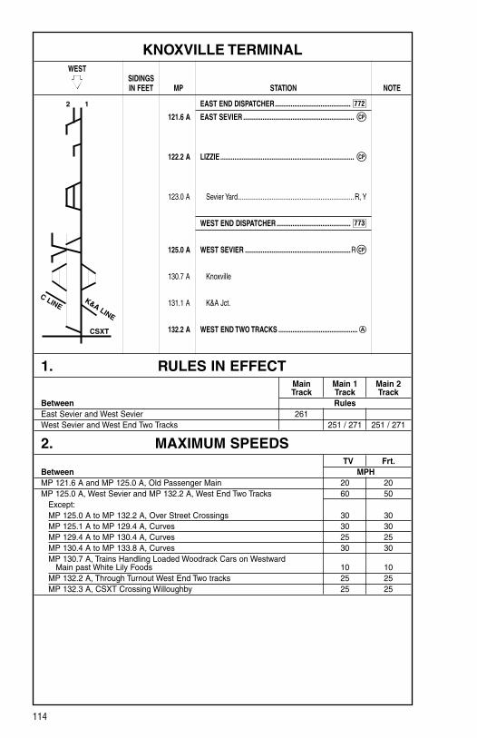
114
772
KNOXVILLE TERMINAL WEST SIDINGS IN FEET MP STATION NOTE
EAST END DISPATCHER ...........................................
121.6 A EAST SEVIER ...............................................................
122.2 A LIZZIE ............................................................................
123.0 A Sevier Yard ..................................................................R, Y
WEST END DISPATCHER ..........................................
125.0 A WEST SEVIER ............................................................R
130.7 A Knoxville
131.1 A K&A Jct.
132.2 A WEST END TWO TRACKS .............................................
1. RULES IN EFFECT Main Main 1 Main 2 Track Track TrackBetween Rules East Sevier and West Sevier 261 West Sevier and West End Two Tracks 251 / 271 251 / 271
2. MAXIMUM SPEEDS TV Frt.Between MPHMP 121.6 A and MP 125.0 A, Old Passenger Main 20 20MP 125.0 A, West Sevier and MP 132.2 A, West End Two Tracks 60 50 Except: MP 125.0 A to MP 132.2 A, Over Street Crossings 30 30 MP 125.1 A to MP 129.4 A, Curves 30 30 MP 129.4 A to MP 130.4 A, Curves 25 25 MP 130.4 A to MP 133.8 A, Curves 30 30 MP 130.7 A, Trains Handling Loaded Woodrack Cars on Westward Main past White Lily Foods 10 10 MP 132.2 A, Through Turnout West End Two tracks 25 25 MP 132.3 A, CSXT Crossing Willoughby 25 25
2 1
C LINEK&A LINE
CSXT
CP
CP
773
CP

115
KNOXVILLE TERMINAL
3. CHECKING LOCOMOTIVE SPEED INDICATORTests for accuracy will be made at the following locations and Engineers will adjust speed in accordance with any inaccuracy.
LOCATION OF TEST MILE SIGNS: WESTWARD EASTWARD MP 129.0 A to MP 130.0 A NONE
NOTE: Tests for accuracy will be made at other locations in addition to those shown. Engineers will choose appropriate locations to check speed indicators.
4. DIESEL UNIT RATINGS DIESEL UNIT RATINGS IN TONS Group 1 Group 2 Group 3 Group 4 Group 5 Group 6
WestwardSevier Yard to West End Two Tracks 3400 4550 5450 6705 7450 8790
EastwardWest End Two Tracks to Sevier Yard 2900 3850 4650 5715 6350 7490
5. LOCOMOTIVE AND CAR RESTRICTIONS
A. WEIGHT RESTRICTIONSLoaded 4-axle cars may be handled up to the weight shown provided the stenciled Load Limit (Weight of car and lading) is NOT exceeded. 286,000 lbs.
B. EQUIPMENT RESTRICTIONSTrailing tonnage must be limited on line segments as shown below, behind the following equipment:1. Empty Multi-level cars.2. Empty Intermodal single-platform flats and such loaded with empty trailers or
containers.3. Empty 85-foot-long or longer flats and such flat cars when loaded with empty
trailers or containers, or loaded with only one (1) trailer or container.4. Empty Intermodal single-axle truck flat car or such cars loaded with empty
trailers or containers.5. Empty single or multiple-unit double-stack (well) cars, or articulated single-
platform (spine) cars. Be governed by Appendix 1 in the System Timetable.
Maximum Safe Trailing Tonnage Southward/ Northward/ Line Segments Between Westward EastwardKnoxville Terminal Sevier Yard and West End Two Tracks 9,600 9,600

116
KNOXVILLE TERMINAL
6. SWITCHES AND DERAILS
A. SPRING SWITCHESSpring switches are located as follows:Milepost Location Normal Position 132.2 A West End Two Tracks Eastward Main Track
B. JUNCTIONS INTERLOCKED
Milepost Location Line/R.R. 131.7 A Knoxville K&A Line, KXHR132.3 A Knoxville C Line, KXHR, CSXT
7. COMMUNICATION INFORMATION Channel 1 Channel 2 Base Station TX and RX TX (RX)West Sevier 56-56 NA
8. DETECTOR INSTRUCTIONSNone.
9. DISTRICT INSTRUCTIONS
A. JOINT TRACKAGETrains and engines of other divisions and foreign lines will use Central Division tracks as shown below:
1. Between Willoughby Jct., MP 132.3 A and Coster Main Track, MP 2.3 C, via City Yard, CSXT and KXHR.
2. Between Willoughby Jct., MP 132.3 A and Bike Track, MP 133.5 A, CSXT.
B. SEVIER MAIN TOWEREastward trains must have permission from the Sevier Main Tower before passing Tobler Lane, MP 134.0 A.
117
KNOXVILLE TERMINAL
9. DISTRICT INSTRUCTIONS (CONT.)
C. SEVIER CLASSIFICATION YARDThe following will govern at the east end of the Classification Yard involving switch target indicators and electric switches:
Aspects of the Switch Target Indicators: FLASHING GREEN Indicates complete route is lined for straight track
SOLID GREEN Indicates a route or part of a route has been lined for straight track
FLASHING YELLOW Indicates a complete route is lined for diverging track
SOLID YELLOW Indicates a route or part of a route is lined for diverging track
When the route has been established, the target lights on the switch machines on the ground, which are involved in the route, will begin to flash. This will be an indication to the crew that a route has been established. When the movement enters the circuit, the target lights will stop flashing and burn continuously with the same color.
No movement will be permitted to enter the confines of the plant unless a route is established by the switch target indicators which are flashing.
Reverse moves may be made within the plant if they do not involve changing the position of the switches, and only after a member of the crew has inspected the route and knows the switches are lined. Crew members must not enter the plant without permission from the Yardmaster after a route has been established.
All vehicle traffic crossing the Utility Road located at the west end of the Classification Yard and pullback leads must have permission from the Yardmaster. If applicable, switching or hump operations must be stopped for the vehicle(s) to cross. Vehicle operators will advise the Yardmaster when they are in the clear.
The derail located at the west end of Classification Track No. 48 (Expedite Bad Order Repair Track) is designated as a Mechanical Department derail.
The application of this derail is under the exclusive control of the Mechanical Department, and will be applied in compliance with Blue Flag Lock Out / Tag Out rules. The normal position for this derail is in the “OFF” position.
The Yardmaster will approve the application of this derail, and will note such on Form SV-1 (Yardmaster Report of On-Track Equipment).
Controls for opening and closing of skate retarders at pullout end of Classification Yard are located in the Car Retarder Tower and are controlled by the Car Retarder Operator.
Indicator lights installed at the entrance of each track at the pullout end indicate the position of the skate retarder. When the light is illuminated, the retarder is open; when the light is dark, the retarder is closed.
If dark indication is received, do not enter track until verification has been made that track is blocked and retarder is open.

118
KNOXVILLE TERMINAL
9. DISTRICT INSTRUCTIONS (CONT.)
C. SEVIER CLASSIFICATION YARD (CONT.)When conditions require placing a car or cars into a Class Track from the east end, the following procedures will be followed:
1. East End Yardmaster will block out Class Track to be used.
2. Crew making move must couple car or cars to cars in track to be used.
3. After couplings are made, shove track west of retarders on east end of track being used.
4. When making switches and cars will be picked up by same crew after switches are completed, Numbers 2 and 3 do not apply.
Under no conditions must cars or engines enter tracks from east end of Class Yard unless tracks being used are properly blocked out.
A retarder overspeed alarm has been installed on the East End Pullback area of John Sevier Yard.
This alarm is controlled by the CRO and is activated when in the CRO’s judgment, a car(s) has exited a group retarder at an excessive speed and the possibility of a roll out is imminent. A siren will sound, and a Red light will rotate for 10 seconds when the alarm is activated. Employees in the pullback area should take action as necessary to prevent personal injury and damage to equipment when time permits.
Engineers operating in the west end of the Classification Yard at Sevier Yard must ascertain from either the Foreman, Hump Utility Man, or Main Tower Yardmaster regarding the status of whether the route from the Classification Yard to the Receiving Yard has been changed. This must be done before pulling out of the Classification Yard.
The following procedure will be followed when Mechanical Department personnel request protection in the Classification Yard at Sevier Yard, MP 123.0 A:
1. Main Tower personnel will instruct the Car Retarder Operator (CRO) to block out the individual Classification Track(s) requested by the Mechanical Department.
2. The Car Retarder Operator will advise the East Tower Yardmaster that a certain track has been blocked out for Mechanical personnel.
Mechanical personnel will apply Blue Signal Protection.

119
KNOXVILLE TERMINAL
9. DISTRICT INSTRUCTIONS (CONT.)
D. SHOP LIMITSThe Shop Limits on the East End, West End, and Brosnan Hill at John Sevier Diesel Shop will be protected by signal indication and electrically controlled derail in control of Mechanical forces.
Before engines enter or exit the Shop limits:
1. Permission must be received from the Diesel Shop Foreman.
2. The signal must be displaying a flashing Yellow indication.
3. The derail must be in the OFF position.
A flashing Blue signal indicates STOP. Permission to enter the Shop limits does not authorize movement onto tracks protected by flashing Blue signal indication inside the Shop limits.
Knoxville District crews going on-duty at the Sevier Yard Diesel Shop MUST contact either the Diesel Shop Foreman or Sevier Main Tower Yardmaster by radio if there are no Mechanical Department employees in the Diesel Shop to advise the crews where the locomotive power is located.
E. SEVIER TOWER — GENERAL INSTRUCTIONSCrews will contact Sevier Tower for location of engines on outbound trains. Inbound trains will place engines as directed by Sevier Tower. All engines are to be shut down per NS-1.
All yard crew foremen at John Sevier Yard will contact the Yardmaster at 1445 within 10 minutes of their on-duty time for instructions. This will be done without fail.
All inbound train crews arriving at John Sevier Yard will arrange to fax Form 1043-BT that applies to their inbound train to the Yardmaster in Main Tower at Fax Number 1112. After faxing, call the Yardmaster or Trainmaster at 1445 to verify receipt by the Main Tower.
All outbound train crews, when reporting for duty at John Sevier Yard, will call the Yardmaster or Trainmaster in the Main Tower at 1445 to receive information con-cerning the outbound Form 1043-BT for their train.
Compliance with the above instructions MUST be complied with to prevent unneces-sary delay to train movements. It will be the responsibility of the Conductor to assure compliance. Failure to comply may result in disciplinary action.
F. RECEIVING YARD, SEVIER YARDAll train and yard cuts arriving and leaving cars in the Receiving Yard, Sevier Yard will be governed by the following instructions before cutting away from cars:
1. Brake pipe pressure must be reduced to 20 PSI above zero as indicated by the equalizing reservoir gauge.
2. Wait until all air has exhausted from the reduction.
3. Close angle cock on locomotive and uncouple from the cars. The above instruc-tions do not change the requirements for securement of cars.

120
KNOXVILLE TERMINAL
9. DISTRICT INSTRUCTIONS (CONT.)
G. TUNNEL TRACK AT SEVIER YARDEquipment exceeding 17 feet in height and exceeding Plate “F” or 73 feet in length will not be authorized for movement on the Tunnel Track at Sevier Yard, MP 123.0 A between the Diesel Shop and the Clean Track Switch due to inadequate clearance.
All movements must have permission from the Yardmaster prior to utilizing the Tunnel Track, MP 123.0 A.
All movements departing the Diesel Shop via the Tunnel Track will notify the Yardmaster when the movement is clear of the Tunnel Track.
All movements departing the Diesel Shop via the Incline or Brosnan Hill will notify the Yardmaster when the limits of the Diesel Shop have been cleared.
H. JOHN SEVIER RECEIVING TRACKS / FORWARDING TRACKSA minimum of 10 hand brakes is required to be applied on cuts left in John Sevier Receiving Tracks 1, 2, 3, 10, 11, and 12. A minimum of eight (8) hand brakes is required in Receiving Tracks 4 through 9. If train length and tonnage dictate, a suf-ficient amount of hand brakes above the minimum will be required.
In Forwarding Yard Tracks 1–10, equipment will be secured with no less than three (3) hand brakes, but a sufficient number is required.
The following procedure will govern employees lining out of Receiving Yard to the hump at Sevier Yard:
1. Yard Switchman or Conductor on job to shove the hump will contact Yardmaster in Main Tower and ascertain track to line out of, and get permission to do so.
2. Yardmaster will determine any conflicting movement with intended shove route before authorizing switchman to line switches to the hump.
3. After getting permission from the Yardmaster to line up out of the Receiving Yard to the hump, the employee lining the switches must check each switch to see that it is properly lined and properly latched down on the entire route from the Receiving Yard up to the hump. Such employee will continually position himself to keep the leading car of the shove in view during the entire shove to the hump. He will be held responsible for all switches that the cut passes over and must not permit any other duty to interfere with protecting this assignment.
4. Before instructing hump crews to proceed to the hump, where possible and visibility permits, the Main Tower Yardmaster will verbally confirm with hump Switchman that the entire route is properly lined before instructing the hump crew to proceed to the hump.
5. After being instructed by the Yardmaster to proceed to the hump, the switchman will notify the Hump Conductor that the entire route is properly lined to the hump and that he is in position to observe the lead car of the shove movement.
6. The Hump Conductor will then inform the Hump Engineer that the intended route is clear, switches are properly lined and that the Engineer may shove the cut to the hump.
121
KNOXVILLE TERMINAL
9. DISTRICT INSTRUCTIONS (CONT.)
H. JOHN SEVIER RECEIVING TRACKS / FORWARDING TRACKS (CONT.)
The following procedure will govern the number of cars that can be cut over the hump at one time:
1. No more than five (5) empty/light loaded cars will be cut at one time. No more than five (5) medium-weight cars will be cut at one time. No more than two (2) heavy/extra heavyweight cars will be cut at one time.
WEIGHT SYMBOLS 0 – 30 Tons — E (Empty) 30 – 50 Tons — L (Light) 50 – 80 Tons — M (Medium) 80 – 100 Tons — H (Heavy) 100 Tons and over — X (Extra Heavy)2. Single, consecutive cuts of extra heavy loads (coal, cement, slag, lime, aluminum
ore, etc.) must not be humped to a clear track(s) until arrangements are made to ensure the track(s) are not fouled by assignments working on the east end of the classification yard until such cars have stopped rolling in the track(s).
The following procedures will apply to the humping operations at John Sevier Yard:
1. Hump Conductor — Before humping begins, Hump Conductor must commu-nicate with the Car Retarder Operator, and have verbal confirmation that the Car Retarder Operator understands that humping is to begin. After verbal con-firmation is received, the hump Trainmaster or Yardmaster must be notified that humping is to begin.
2. Car Retarder Operator — Prior to giving verbal confirmation of the understanding that humping is to begin, the Car Retarder Operator must check all switches to see that they are in proper position, operator retarders to see if there is indication they are operating, and check to see that skate retarders are indicating to be in the proper position. Siren must be sounded prior to cutting off first car.
3. While the hump is not in use, the Car Retarder Operator must have the master retarder in the closed position.
EXCEPTION: Master retarder may be opened while maintenance is being performed.
4. Before tracks are shoved or trimmed in the Classification Yard, the Hump Conductor must notify the East End Yardmaster of the move to be made.
5. Precautions must be taken to ensure that cars are coupled in curves prior to trim-ming, to eliminate possible damage due to mismatched or by-passed couplers.
6. Cuts of cars being pulled from either end of the Class Yard must be inspected by an employee located at the clear point of the track to ensure all couplers are properly aligned. This does not apply to cuts of cars that have been walked their entire length during coupling operations.

122
KNOXVILLE TERMINAL
9. DISTRICT INSTRUCTIONS (CONT.)
H. JOHN SEVIER RECEIVING TRACKS / FORWARDING TRACKS (CONT.)
Crews shoving equipment into the John Sevier Forwarding Yard, Knoxville, TN, will be required to have a minimum of five (5) cars equipped with operative air brakes next to the locomotive when the total equipment length will exceed the footages below:
Track Footage FT01 ..................................8,000 FT02 ..................................8,000 FT03 ..................................8,000 FT04 ..................................5,000 FT05 ..................................5,000 FT06 ..................................4,200 FT07 ..................................4,200 FT08 ..................................4,200 FT09 ..................................4,200 FT010 ................................2,800
Speed must be controlled during all shove movements and movement must stop immediately when shove lights are extinguished. Prior to beginning shove moves into the Forwarding Yard, crew will ascertain the tonnage and footage of equipment being shoved. This information will be Job Briefed with all crew members.
Shove lights located on the ground are protection to shove Forwarding Yard Tracks from the east end of John Sevier Yard without a member of the crew being at, on, or ahead of the leading car in the shove.
If the light should go out during a shove move, the move must be stopped. The employee on the ground directing the shove is responsible for watching the shove lights and taking appropriate action to stop the shove if the light goes out. In the event of a malfunction of the ground shove light at the east end of the forwarding tracks, shove movement will be conducted in accordance to applicable rules.
Cars or trains left standing at the west end of FT01 through FT09 will be left to occupy the shove light circuit at the west end. Crews will contact the East End Yardmaster to verify the circuit is occupied and shove light is out indicating track is occupied.
Malfunctions must be reported immediately to the Yardmaster, who will notify the C&S personnel.

123
KNOXVILLE TERMINAL
9. DISTRICT INSTRUCTIONS (CONT.)
I. OLD PASSENGER MAINCertain trains arriving at Sevier Yard will, when directed, be fueled at a “Direct To Locomotive” (DTL) fueling site. Engineers will stop their locomotives at the designated fueling site as directed by the Main Tower.
There are three (3) DTL fueling sites in John Sevier Yard. They are located just east of the road crossing at MP 123.9 A on the Old Passenger Main at MP 122.5 A and on the south side of the shed track. The fueling sites on the Old Passenger Main are designated by sign. Engineers will stop their engines on the south side of the shed at the direction of the Main Tower.
While at the DTL, the train and/or locomotive must not be moved until the crew mem-bers have been advised that the fueling is complete, all hoses are detached and the DTL fueling personnel are in the clear. The fuel track is equipped with a Yellow strobe light that will be flashing when fuel is being pumped from the truck into the locomotives. The absence of this light, or the light being off, does not relieve crew members from ascertaining that fueling is complete, hoses down, and personnel are in the clear.
J. ASHEVILLE INBOUNDEmployees are prohibited from using the walkway on the North side of the Asheville Inbound between the North Side of the Shed switch and the Bronsnan Hill switch.
K. MOVEMENT WITHIN SEVIER YARDAll trains entering Sevier Yard must have oral permission from the tower before entering the Receiving Yard tracks. All movements within Sevier Yard will be under the direction of Sevier Main Tower.
Prior to any two (2) opposing movements being made into the same track simultane-ously, or any two (2) or more movements being made to adjacent tracks simultane-ously, the Yardmaster will advise affected crews of the movements to be made.
L. SEVIER YARD — GENERAL INSTRUCTIONSCabooses and wheel cars may be cut off in motion and allowed to roll to a coupling at Sevier Yard.
Derails applied by Engineering and Mechanical will be approved by the Terminal Officer on-duty and documented by the Yardmaster on Form SV-1 (Yardmaster Report of On-Track Equipment).
Yardmasters at John Sevier Yard, MP 123.0 A, will issue all track time for movements of On-Track equipment. Form SV-1 will be utilized for documentation.
All crossings throughout the Terminal are designated as public crossings for protection purposes.
Cardboard, and/or any item that will obstruct vision, will not be permitted in the win-dows of locomotives/yard engines.
The grass bank located adjacent to the north end of the tunnel adjacent to the Stock Pen Track is not an authorized walkway.

124
KNOXVILLE TERMINAL
9. DISTRICT INSTRUCTIONS (CONT.)
L. SEVIER YARD — GENERAL INSTRUCTIONS (CONT.)Employees are prohibited from riding the steps of engines moving through retarders at John Sevier Yard, MP 123.0 A.
Light engine movements over the Master Retarders and all group retarders will not exceed 5 MPH.
Do not cut empty rail cars coupled to loaded rail cars over the hump at Sevier Yard. This change is made due to empties popping up out of the master when coupled to loads, causing damage to master.
As part of the Job Briefing, before humping begins, the Hump Conductor must com-municate with the East Tower Yardmaster to ascertain what tracks in the Class Yard are blocked out. The East Tower Yardmaster will provide the requested information to the Hump Conductor when requested. The Hump Conductor must also communicate with the CRO and have verbal confirmation that the CRO has the same tracks blocked and that humping is to begin. After confirmation is received from the CRO, the Main Tower must be notified that humping is to begin.
Yard or train movements handling five (5) or more cars in a westward direction on the High-Line Track at Sevier Yard must arrange to have a minimum of five (5) cars with operative air brakes next to the engine consist to assist in controlling the train speed and for additional stopping.
A new walking mat has been installed on the walkway on the hump. Before crews begin humping at the beginning of their shift, and also after their minutes, the Foreman must inspect the mat edges and seams for any loose or frayed ends. Any problems with the mat should be immediately reported to the Main Tower Yardmaster or Trainmaster on-duty.
The calling times for John Sevier Yard assignments for employees called off the extra boards for the purpose of filling vacant positions will comply as follows:
4:30AM to 6:00AM: for assignments starting between 6:30AM and 8:00AM 12:30PM to 2:00PM: for assignments starting between 2:30PM and 4:00PM 8:30PM to 10:00PM: for assignments starting between 10:30PM and
12:00PM Midnight
Employees must report for duty at the assigned or report time given. Employees called from the extra board must report within two (2) hours from the time Crew Management Center first initiates a call to the employee. Employees should do all possible to arrive at the appointed start times if a full two (2) hours is not possible for reasons uncon-trolled by the Crew Management Center. EXCEPTION: Employees called to report for duty at 5:30AM will have one (1) hour and 30 minutes from the time the Crew Management Center first initiates a call to the employee.
For security purposes, keypad locks have been installed on both doors of the West End Utility Shack at Sevier Yard. The entry code is 531 (both locks). This information should NOT be shared with non-employees.
All locomotives left unattended within the perimeter of the John Sevier Diesel Shop, Knoxville, TN, are required to be secured with 100% hand brakes.
Employees are prohibited from riding equipment over a hump retarder. EXCEPTION: An employee can ride the locomotive platform maintaining a secure hand hold or ride in the operating compartment of the locomotive when moving over a retarder.

125
KNOXVILLE TERMINAL
9. DISTRICT INSTRUCTIONS (CONT.)
M. CAR RETARDER OPERATOR (CRO)The CRO will control speed of spine or double-stack cars for 4 MPH or less coupling. Following cars must not be cut off until spine or double-stack cars have passed the second control point (group retarder).
1. After lining necessary switch or switches to properly block out a track, the blocking pins must be placed in the holes provided on the retarder console at the switch lever of the blocked-out track.
2. When it is desired to manually operate the master retarder to the fully closed (heavy) position in order to hold a car or cut of cars in a standing position, the master retarder should be placed in the fully closed (heavy) position, and wait for the “pump light” to extinguish before the car or cut of cars come to a complete stop. Should the pump light fail to extinguish, change the retarder setting to the next lighter position. This is necessary to prevent the possibility of overheating the hydraulic oil, which may result in a system shutdown.
3. Crews pulling cars that have been held in retarders on the west end of John Sevier Classification Yard must ascertain that the wheels are on the rail before pulling.
4. CROs are not to allow cars to pass on the adjacent track in the Class Yard when the track is shown to be fouling, as indicated by the track light on the CRO Panel Board.
5. In order to prevent the possibility of overspeeds in the event of power failure, retarders will be left as follows during idle times:
(a) The first section of each retarder is to be left on Light Retardation. (b) All other sections of each retarder are to be left on Heavy Retardation.
A voltage alarm has been installed in the Car Retarder Operator (CRO) Tower at John Sevier Yard (MP 123.0 A). The voltage alarm is designed to activate when the humping operation has moved to back-up battery power.
Humping operations will stop immediately in the event that the voltage alarm is activated. The Car Retarder Operator is responsible for stopping the humping operation by notifying the Hump Utility assignment, and then by notifying the Yardmaster in the Main Tower and the Yardmaster in the East Tower.
The humping operation will not begin until C&S Department personnel advise that the power has been restored.
The following procedures will be followed when a switch out of correspondence indica-tion (a single stroke gong in the control console will ring and a flashing Red light will show in the center of a switch lever) is received in the Car Retarder Tower:
1. Car Retarder Operators must immediately stop the humping operation.
2. If possible, hold cars that have not exited the master in the master retarder.
3. Look for a misrouted car to determine which switch is out of correspondence.
4. Car Retarder Operators are prohibited from manually lining such out of corre-spondence switches while the humping operations are in progress.

126
KNOXVILLE TERMINAL
9. DISTRICT INSTRUCTIONS (CONT.)
M. CAR RETARDER OPERATOR (CONT.)5. In an effort to correct the out of correspondence indication, after the humping
operation has been stopped, operate the switch manually to determine that switch follows the movement of lever.
6. If this fails to correct the condition, place switch lever in manual position cor-responding with actual position of the switch points indicated by White light on control panel and then arrange for examination of the switch with the out of cor-respondence indication.
7. If C&S personnel are not available to inspect switch with out of correspondence indication, a Terminal Officer will inspect the switch.
8. Cars must not be allowed to pass over the switch until inspection is completed.
NOTE: C&S personnel should be contacted to check the switch even if the out of cor-respondence indication is corrected when manually throwing the switch.
N. CITY YARD, KNOXVILLE, TN, MP 131.0 A–COSTER, MP 2.0 C1. Cars switched in the West Yard and East Yard at City Yard, MP 131.0 A, and
Coster Yard, MP 2.0 C, will not be cut off in motion, but will be shoved to couplings.
2. The Foreman on Yard assignments TK06, TK23 and TK61 will be responsible for providing the following information to the Yardmaster:
(a) Complete and detail City Yard turnover with a copy of complete work order. (b) Status of CSXT and KXHR interchange deliveries. (c) Explanation for any overtime incurred.
3. Close clearance exists between EY06 and No. 1 eastward Main Track, City Yard, MP 131.0 A, Knoxville, TN. Employees working in this area must use proper caution.
4. When delivery is made to CSXT on Interchange Tracks 1 through 4, sufficient hand brakes will be applied on the south end of track to properly secure cars. In addition, the angle cock on the south end will be left open, and the angle cock on the east end will be left closed.
5. The following tracks at Coster Yard are designated as interchange tracks between Norfolk Southern and the Knoxville & Holston River Railroad (KXHR):
Oakwood No. 1, Oakwood, No. 2, Metler Track Equipment left standing in any of these tracks must have a minimum of five
(5) hand brakes applied, or a sufficient amount.
6. Road trains are prohibited from using any other tracks at Coster Yard, MP 2.0 C, except the three (3) designated interchange tracks noted above, along with the Coster Lead which leads to the interchange tracks.
As information, the aforementioned tracks are numbered as follows from the southward Main Line at Coster, MP 2.0 C:
Oakwood No. 1 — Oakwood No. 2 — KXHR No. 1 — KXHR No. 2 — KXHR No. 3
Be on the lookout for bad footing conditions, all tracks at Coster Yard.

127
KNOXVILLE TERMINAL
9. DISTRICT INSTRUCTIONS (CONT.)
N. CITY YARD, KNOXVILLE, TN, MP 131.0 A–COSTER, MP 2.0 C (CONT.)
7. Be on the lookout around ALL TRACKS at White Lily Industry, MP 130.5 A, for grated ground drains between all trains. Drains are recessed at various depths below the normal walking surface and can cause a tripping hazard if stepped in. The 14 drain locations have been marked with Orange fluorescent paint and must be avoided while working in this area. You are also reminded of the close clearances of all tracks and dock area, and to protect yourself accordingly.
8. When switching White Lily Flour Company, MP 130.5 A, the train line air will be cut in on equipment to be switched out or spotted.
9. Close clearance exists between ALL tracks at White Lily, MP 130.5 A.
10. It will not be permissible to allow equipment secured on No. 2 Main Line east of the West Yard Crossover, MP 131.6 A, to be cut off in motion with the inten-tion to couple into equipment secured on No. 2 Main Line west of the West Yard Crossover.
11. In an effort to show reported interchanges on a real time basis, all crews inter-changing cars to the CSXT and the KXHR will advise CYO by radio or phone at 404-589-6131 or 404-589-6088 of the actual time the cars are delivered to the interchange point. Advise CYO of the number of cars set off including the head and rear car numbers.
Interchange for the CSXT will be on the CSXT Interchange Track at 22nd Street. KXHR Interchange will be at Coster Yard and at East City Yard tracks.
O. CEMEX CEMENT PLANT, MP 124.5 AA Blue flag and derail is located at the railroad gate across the access track to Cemex Cement Plant, MP 124.5 A, John Sevier Yard. NS Yard assignments will not enter the limits of Cemex Cement unless the Blue flag and Blue derail have been removed.
Should NS Yard assignments find the Blue flag and derail displayed/applied, then contact the Yardmaster.
P. REPAIR TRACKS SEVIER YARDThe Mechanical Department at Sevier Yard has installed spotting signs for inbound Repair Tracks 1, 2 and 3.
When spotting cars on Repair Tracks 1, 2 and 3 at John Sevier Yard, be governed by the newly installed Blue spotting signs with White lettering reading “SPOT KNUCKLE OF LEAD CAR HERE”. The signs are approximately 50 feet east of the derails and provide a standard location for safe spotting. After spotting, always make sure cars are properly secured with a minimum of two (2) hand brakes.

128
CHATTANOOGA TERMINAL WEST SIDINGS IN FEET MP STATION NOTE
CT DISPATCHER ........................................................
331.3 TENBRIDGE .........................................................Y 1
331.7 BOYCE ........................................................................ Y
332.4 CITICO JCT. ............................................................... Y
333.3 PIERCE ........................................................................ Y
334.6 WEBB ............................................................................
DeButts Yard .................................................................. R
336.0 PRATT ...........................................................................
337.1 EAST END AVENUE .....................................................
337.5 MAIN STREET ..............................................................
338.2/ 243.1 A 23RD STREET ................................................................
AGS 2.1 NORTH TUNNEL ...........................................................
AGS 3.2 SOUTH TUNNEL ...........................................................
AGS 5.3/ 248.1 A WAUHATCHIE ...............................................................
248.1 A HBD-DED (Wauhatchie, TN)
STATION PAGE INFORMATIONNOTE 1: Chattanooga Terminal section governs between Tenbridge and Wauhatchie.
1. RULES IN EFFECT Main Main 1 Main 2 Track Track TrackBetween Rules Tenbridge and Pierce 261 261Pierce and East End Ave. 261East End Ave. and N. Tunnel 261 261N. Tunnel and S. Tunnel 261S. Tunnel and Wauhatchie 261 261
2 1
CSXT
CSXT
CP
CPDB
CP
CP
CP
CP
CP
CP
CP
CP
CP
774

129
CHATTANOOGA TERMINAL
1. RULES IN EFFECT (CONT.)
RAILROAD CROSSING AT GRADE INTERLOCKED
Location Line/R.R. Wheland CSXT (see Note 1)NOTE 1: (a) When NS movement is stopped by stop indication at CSXT crossing and signal
does not clear, after approximately one (1) minute, an employee will go to the time release box. If indicator light is burning, this indicates CSXT signals are in the stop position and the push button marked “clear” may be pushed. If indicator light is dark, this indicates the CSXT signal is clear for an approaching train, and clear button must not be pushed. After six (6) minutes have expired, and no CSXT train is evident, the clear button may be pushed.
(b) After expiration of time, which is an additional six (6) minutes the NS signal will clear. If the signal does not clear, movement may proceed at Restricted Speed, after contacting NS CT Dispatcher to ascertain no CSXT movements are approaching, CSXT signals indicate stop, and burning fusees are placed on conflicting CSXT tracks.
NON-INTERLOCKED Location Line/R.R. Chestnut Street CSXT (Note 1) 33rd Street CSXT (Note 2) NOTE 1: Stop signs are located at CSXT tracks on both sides of NS crossing.NOTE 2: The stop signs are located at CSXT crossing 33rd Street. ALL MOVEMENTS MUST
STOP AT THIS LOCATION IN EITHER DIRECTION.These signs have periodically been stolen. Therefore, if the signs are not found in position, the fact should be reported to the operator/dispatcher and movements must stop short of CSXT crossing at location where stop signs would normally be displayed.
2. MAXIMUM SPEEDS Main TracksBetween MPHMP 235.1 A and MP 238.0 A 40 Except: MP 236.0 A, Through Crossovers Williams 25 MP 235.0 A, Through Crossover Jersey 40 MP 238.0 A, Through Crossovers and Turnout Citico Jct. 40 MP 238.7 A, Through Turnout Pierce 25MP 331.2, Tenbridge and MP 337.0, East End Avenue 35 Except: MP 331.2, Through Crossovers Tenbridge 25 MP 331.9, Through North Crossovers Boyce 25 MP 331.9, Through South Crossovers Boyce 15 MP 331.9, Through Turnouts 2 Wye and 1 Wye Boyce 15 No. 1 Wye Track 15 No. 2 Wye Track 15 MP 334.6, Through Crossover Webb 20 MP 334.6, Through Alternate Inbound Turnouts Webb 10 CNO&TP Zero Track — MP 334.7, Webb to MP 337.0, East End Ave. 20 MP 336.0, Through Crossover Pratt 20 MP 336.0, Through Turnout Zero to Forwarding Yard (Pratt) 10MP 337.0, East End Avenue and MP 0.0, Ship Yard 15MP 0.0, Ship Yard and MP 3.2, South Tunnel 25 Except: MP 2.2, Through Turnouts North Tunnel 25MP 3.1, Through Turnouts South Tunnel 25

130
CHATTANOOGA TERMINAL
2. MAXIMUM SPEEDS (CONT.) Main TracksBetween MPHMP 3.2, South Tunnel and MP 5.5, Wauhatchie No. 1 Track 50 No. 2 Track 45 Except: MP 3.2 to MP 3.9 (Tracks 1 & 2), Curves 25 MP 5.3, Through Crossovers Wauhatchie 25Auxiliary Tracks: Chattanooga Traction Company 10 Except: MP 1.3V to MP 1.5V, Curve at Top of Mountain 5 MP 4.1 CD to MP 4.3 CD 5 MP 2.8V to MP 2.9V, Soft Fill Side 5Bunges Edible Oil Company, Over Scales 3River Belt, Between Superspun Ave and 19th Street 5CSXT Wahatchie Yard 10DeButts Yard, Over All Switches in and out of Receiving Yard, Classification Yard, Forwarding Yard, and Over Alternate Inbound Bridge (Hop Skip Bridge) 10Citico Jct., West Inbound lead Through Turnout 10DeButts Yard, All industry tracks and leads 10DeButts Yard, All Belt tracks including the Belt Yard 10DeButts Yard, Over Street Crossings listed below: 8 Broad Street
Market Street Main Street King Street Cowart Street Thirteenth Street Rossville Avenue McCallie Avenue Bailey Avenue Third Street Rossville Blvd. Central Avenue Alton Park Blvd. Forty-Fifth Street Thirty-Eighth Street
NOTE: Trains and engines must stop and flag over the above street crossings by a member of the crew with proper signals, unless crossing Flagmen are on-duty or other approved signals are used to warn traffic. After the leading engine or cars has cleared the crossing, the speed may be increased not to exceed 10 MPH.
DeButts Yard, movements in all tracks in the Receiving Yard, including the East and West Thoroughfares will operate at Restricted Speed. Trains moving over the switches leading to any of these tracks must operate at 10 MPH until the trailing end of their movement has cleared the switch.
3. CHECKING LOCOMOTIVE SPEED INDICATORTests for accuracy will be made at the following locations and Engineers will adjust speed in accordance with any inaccuracy.
LOCATION OF TEST MILE SIGNS:WESTWARD EASTWARD NORTHWARD MP AGS 4.0 to MP AGS 5.0 MP 234.0 A to MP 233.0 A MP 328.0 to MP 327.0
NOTE: Tests for accuracy will be made at other locations in addition to those shown. Engineers will choose appropriate locations to check speed indicators.

131
CHATTANOOGA TERMINAL
4. DIESEL UNIT RATINGSSee District Instructions for trains departing Chattanooga Terminal.
5. LOCOMOTIVE AND CAR RESTRICTIONSLoaded 4-axle cars may be handled up to the weight shown, provided the stenciled limit (weight of car and lading) if not exceeding 286,000 lbs.
6. SWITCHES AND DERAILS
A. FUEL RACK AND DIESEL SHOPThe fuel rack and diesel shop area at DeButts Yard are protected by outreach derails and Blue lights. The purpose of these derails is to prevent unauthorized movement of locomotives or cars into the shop facility. Out reach derails are remotely controlled by the fuel rack Supervisor in the diesel shop at DeButts Yard.The north set of derails and lights are located on the inbound and outbound leads just north of the Citico Creek Bridge. Two (2) reflective signs, one located on the east side of the inbound lead and one located on the west side of the outbound lead, provide warning for consists leaving and arriving the Shop facility. The signs state:
STOP NOTIFY FUEL RACK SUPERVISOR BEFORE
PROCEEDING BEYOND THIS POINT AND NOTIFY FUEL RACK SUPERVISOR
WHEN MOVEMENT HAS CLEARED DERAIL
The south set of derails and Blue lights are located on the inbound lead and Norris Lead halfway between Third Street Bridge and McCallie Avenue Bridge. One (1) lighted sign is located on the west side of the Norris Lead.
All movements into and out of DeButts Diesel Shop Facility must stop clear of these derails and comply with instructions posted.
B. MOUNTAIN LINE RUNAROUND (K45 & K35)The Mountain Line Runaround (K45) and Main Line Runaround (K35) are both equipped with hand-thrown derails. The normal position for these derails are locked in the OFF position unless cars are stored on these tracks.
C. C&D JCT. TRACKSThe normal position for derails protecting C&D Jct. tracks are locked in the OFF posi-tion unless cars are stored on these tracks.
D. BLUE SIGNAL DERAILThere is a permanent Blue Signal derail is located 168 feet south of the north switch on East Thoroughfare Track. This derail is under exclusive control of the Mechanical Department and will be locked in the OFF position at all times unless being used by the Mechanical Department to Blue Signal East the Thoroughfare.

132
CHATTANOOGA TERMINAL
6. SWITCHES AND DERAILS (CONT.)
E. JUNCTIONS INTERLOCKED
Milepost Location Line/R.R. 243.1 A/338.5 23rd Street Chattanooga CSXT248.1 A Wauhatchie CSXT, Alabama Division 332.4 Citico Jct. A Line, Georgia Division
7. COMMUNICATION INFORMATIONNone.
8. DETECTOR INSTRUCTIONSNone.
9. DISTRICT INSTRUCTIONS
A. EXCESSIVE CURVATURE Listed below are tracks with curvature of 12 degrees, 30 minutes or greater:
Milepost Location Curvature 1.4M Mountain Line 17.0 degreesJIT Lead JIT Industries 18.5 degrees240 A Quaker Oats 16.5 degreesCG 2.4 Central of Georgia Cutoff 14.5 degrees242.6 A Old Passenger Main 13.5 degrees3.8 M Mayo Lead north Chattanooga 13.0 degrees331.2 South leg of Wye at Tenbridge 14.0 degreesRefer to the Equipment Restriction Section of the System Timetable.
B. JOINT TRACKAGE Trains and engines of other divisions and foreign lines will use Central Division tracks as shown below: Between DeButts Yard, MP 240.0 A and Wauhatchie, MP 248.1 A,
Alabama Division. Between Jersey, MP 335.0 A and Summit, MP 230.0 A, Georgia Division.
C. JOINT TRACK AUTHORITY IS REQUIRED AT THE FOLLOWING LOCATIONS:
Between Tenbridge, MP 331.2 and Hixson, TN, MP 328.7 (CT Dispatcher) and south end between Jersey, MP 235.0 A and Summit, MP 230.0 A, CT Dispatcher and Georgia North End Dispatcher..
D. WHISTLE AND BELLWhistle will be blown and bell will be rung at ALL CROSSINGS in DeButts Yard.

133
CHATTANOOGA TERMINAL
9. DISTRICT INSTRUCTIONS (CONT.)
E. TRAFFIC AT POWER HOUSEDue to the amount of traffic at the road crossing by the Power House, which leads into the north end of the Fuel Rack, DeButts Yard, movements over this crossing must be preceded by a flagman.
F. DIESEL SHOPEngines or engine consists moving into or out of the Diesel Shop must have a crew member positioned on the front of the lead unit or on the ground proceeding the movement except when the Engineer is operating short hood forward on the lead end of the movement.
All road crews are to call the car foreman on the road channel when departing the DeButts Yard Diesel shop so that you can be given your EOTD number and then test your emergency feature.
G. TINKER STREET BRIDGEBefore leaving the Diesel Shop, it will be necessary for Engineers to notify the Main Tower. When moving northward from the Diesel Shop to Tinker Street Bridge, it will be necessary to stop in the clear of the first crossover south of Tinker Street Bridge and call the Main Tower for further instructions
H. MIDDLE ENGINE LEADAll southward traffic moving to the Diesel Shop will use the East Engine Lead. All northward traffic moving from the Diesel Shop will use the Middle Engine Lead. Dwarf signals governing train movements are located on Engine Thoroughfare Tracks. Northward movements are governed by three (3) signals. Southward movements are governed by two (2) signals.
I. OUTBOUND FREIGHT LEADA stop sign is located on each side of Outbound Freight Lead, 250 feet north of the No. 5 “P” signal governing southward movements. A train or engine moving southward on Outbound Freight Lead must stop at the stop sign and receive permission from Yardmaster on-duty, to pass the stop sign. Permission must be received from the Yardmaster before movement in any direction is made through electric switches at north end of Forwarding Yard.
J. INSTRUCTIONS FOR MAIN TRACK MOVEMENTPermission must be received from Main Tower before entering Zero Track.

134
CHATTANOOGA TERMINAL
9. DISTRICT INSTRUCTIONS (CONT.)
K. RECEIVING YARD AT DEBUTTSAll train and yard movements entering the Receiving Yard at DeButts will be governed by the following:
1. Train and yard movements MUST communicate with the Main Tower Yardmaster to determine the Receiving Yard track to be used.
2. When yarding trains or cuts in the Receiving Yard in the East or West Thoroughfare and Tracks 1, 2, 11, or 12, a sufficient number of hand brakes must be applied. Hand brakes will not be required in Receiving Yard Tracks 3 through 10.
L. FORWARDING YARD AT DEBUTTSHand brakes will not be required in Forwarding Tracks 1–10.
M. INDUSTRIAL LEADSAnytime cars are left on any of the following Industrial Leads: — TAG — Central of Georgia Cutoff — Mtn. Line — Valley — C&D Line
The CT DIspatcher must be notified, providing number of cars left standing and location.
Two (2) hand brakes will hold any number of cars on the following tracks: — Local Yard 1–5 — Belt Yard 1–8 — Riverport Runaround and Lead — Dupont Service Yard
A C-102 brake test must be performed on the two (2) secured cars.
N. RIDGE BELT (CENTRAL OF GEORGIA)Per 49 CFR (Code of Federal Regulations), Part 213 — Track Safety Standards, Subpart A — General Section 213.4 entitled Excepted Track, the Ridge Belt in DeButts Terminal located between MP 445.6 and 28th Street on the Central of Georgia (approx. 1.5 miles) is hereby designated as “EXCEPTED TRACK”. The track on bridges and bridge approaches (100 feet each side of a bridge) and the track within the limits of public streets or highways is EXCLUDED from the “EXCEPTED TRACK”.
No occupied passenger trains may operate on this line segment.
No freight trains may operate with more than five (5) cars required to be placarded by the Hazardous Materials Regulations (49 CFR, Part 172).

135
CINCINNATI TERMINAL SOUTH SIDINGS IN FEET MP STATION NOTE
NORTH END DISPATCHER ........................................
0.0 Cincinnati
2.3 Gest St. Yard
2.6 8TH STREET ...................................................................
2.8 OH/KY State Line
3.0 LUDLOW .....................................................................R
1. RULES IN EFFECT Main 1 Main 2 Track TrackBetween Rules Gest Street and 8th Street 261 261 8th Street and Ludlow 261 261
A. RAILROAD CROSSING AT GRADE NON-INTERLOCKED
Milepost Line/R.R. Loop Track and West Lead (Note) CSXTNOTE: All trains and engine movements must stop and not proceed until no conflicting move-
ments are evident.
2 1
103
CP

136
CINCINNATI TERMINAL
2. MAXIMUM SPEEDS Main TracksBetween MPHCSXT, MP BE 6.7, Winton Place and CSXT, MP BE 5.0 35 Except: CSXT, MP BE 6.7, Through Turnout Winton Place 35 CSXT, MP BE 5.0 to CSXT, MP BE 4.1, Eckler 20 Except: CSXT, MP BE 4.1, Through Turnout Eckler 20 I&O, NA Tower to East Norwood 25Clare and Red Bank Track No. 1 10Track No. 2 25 Except: Through Interlocking Plant to Clare Yard 10Red Bank, Through Interlocking 25Red Bank and Valley 25Red Bank and Rendcom Jct. 10Oakley and Penn 25Penn and East Norwood 25MP CT 0.0 and MP CT 9.0, Old Main Line 10MP 0.0, Cincinnati and MP 2.6 10MP 2.6, Through C. U. T. 15MP 2.6 and MP 3.0, Ohio River Bridge 20MP 3.0, Through Crossover Ludlow 25Auxiliary Tracks: Sharonville and Evendale, All Yard Tracks 10 Except: Cincinnati, All Yard Tracks 10
3. CHECKING LOCOMOTIVE SPEED INDICATOREngineers will choose appropriate locations to check speed indicators.
4. DIESEL UNIT RATINGSSee District Instructions for train departing Cincinnati Terminal.
5. LOCOMOTIVE AND CAR RESTRICTIONS
A. WEIGHT RESTRICTIONSLoaded 4-axle cars may be handled up to the weight shown provided the stenciled Load Limit (Weight of car and lading) is NOT exceeded. 286,000 lbs.

137
CINCINNATI TERMINAL
5. LOCOMOTIVE AND CAR RESTRICTIONS (CONT.)
B. EQUIPMENT RESTRICTIONSTrailing tonnage must be limited on line segments as shown below, behind the following equipment:1. Empty Multi-level cars.2. Empty Intermodal single-platform flats and such loaded with empty trailers or
containers.3. Empty 85-foot-long or longer flats and such flat cars when loaded with empty
trailers or containers, or loaded with only one (1) trailer or container.4. Empty Intermodal single-axle truck flat car or such cars loaded with empty
trailers or containers.5. Empty single or multiple-unit double-stack (well) cars, or articulated single-
platform (spine) cars. Be governed by Appendix 1 in the System Timetable.
Maximum Safe Trailing Tonnage Southward/ Northward/ Line Segments Between Westward EastwardCincinnati Terminal Cincinnati and Ludlow See Note 1 See Note 1 NOTE 1: See District instructions for trains departing Cincinnati Terminal.
C. TRAILING TONNAGE RESTRICTIONS —RAILRUNNER* EQUIPMENT Maximum Safe Trailing Tonnage Empty Loaded Less than Light Load 28 Tons Line Segments Between 18 Tons 18–27 Tons or MoreCincinnati Terminal New River Jct. and 4,400 4,400 5,200 (To/From Lake Div.) Gest Street (Via CSXT)NOTE: *RailRunner Block MUST TRAIL RoadRailers.
6. SWITCHES AND DERAILS
A. INTERLOCKED SWITCHESInterlocked switches are controlled as follows:Milepost Location By Operators1.9 8th Street North End Dispatcher2.0 Intermodal North End Dispatcher
B. JUNCTIONS INTERLOCKED
Milepost Line/R.R. Valley, Rendcomb Jct. (Note 1) Lake Div.Hopple St. — Loop Track Connector (Note 2) CSXT Clare Yard, Red Bank (Note 3) Lake Div.Bond Hill — East Norwood (Note 4) I&O NOTE 1: Interlocking at Valley, and Rendcomb Jct., are controlled by Lake Division Train
Dispatcher, Ft. Wayne, IN. NOTE 2: Interlocking with CSXT at Hopple Street and at foot of loop West lead track at Gest
Street yard are controlled by CSXT. Movements are governed by CSXT Rules, Timetable and Special Instructions.
NOTE 3: Clare and Red Bank interlockings are controlled by the Lake Division Chicago Train Dispatcher at Ft. Wayne, IN.
NOTE 4: Bond Hill to East Norwood is controlled by the I&O Dispatcher.

138
CINCINNATI TERMINAL
7. COMMUNICATION INFORMATION Channel 1 Tone CSXT 08-08 1 McCollugh Yard 85-85 519 I&O 74-74
8. DETECTOR INSTRUCTIONSNone.
9. DISTRICT INSTRUCTIONS
A. JOINT TRACKAGE1. Trains and engines of the Central Division will use track of other divisions, and
foreign lines, in accordance with their Timetables, Rules and Regulations as shown below:
Between Gest St. Yard and Sharonville, Lake Div., CSXT, I&O. Gest St. Yard and Queensgate Yard, CSXT.
2. Trains and engines of other division and foreign lines will use Central Division tracks as shown below:
Between Gest St. Yard, MP 0.0 and Ludlow, MP 3.5, Lake Div., I&O, CSXT.
B. CINCINNATI TERMINAL 1. All Train and Engine service employees performing services in Cincinnati Terminal
must have in their possession the current CSXT Superintendent’s Bulletins prior to traversing, or fouling CSXT trackage as required by CSXT Operating Rule #5. CSXT Bulletins are issued each calendar quarter and will indicate the most recent edition published. This information is available in the Office of the Terminal Superintendent at Gest Street along with DI Tower.
2. Equipment left unattended in Cincinnati Terminal must be properly secured as indicated below:
One (1) car — One (1) hand brake Two (2) cars — Two (2) hand brakes Two (2) or more cars — Two (2) hand brakes plus a sufficient number nec-essary to ensure securement
EXCEPTIONS: • Equipment left at Sharonville Yard intended for inspection by charging the air
brake system, as designated by the Yardmaster at Sharonville, will require a minimum of five (5) hand brakes.
• Equipment left at Bulkmatic Industry, MP CT 9.0 will require securement on both ends of the equipment. A minimum of six (6) hand brakes must be applied, with no less than three (3) on each end.
• Equipment left standing at Matlack Industry, MP CT 4.0 will require secure-ment on both ends. A minimum of five (5) hand brakes are required on the East End of the equipment and a minimum of three (3) hand brakes are required on the West End.

139
CINCINNATI TERMINAL
9. DISTRICT INSTRUCTIONS (CONT.)
B. CINCINNATI TERMINAL (CONT.)3. All switches at Gest Street Yard must be left in corresponding position aligned for
lead movement unless otherwise instructed by DI Tower. Before dropping cars at Gest Street Yard, it must be determined that there is no excessive dimensional equipment on an adjacent track which would effect clearance.
4. All grade crossings in the Intermodal facility at Gest Street Yard must be pro-tected when shoving cars.
All transfer movements departing Gest Street or Sharonville Yard en route to Clare Yard or Berry Yard must display a marker on the rear car while in transit. The Conductor of each affected movement will be responsible to ensure compli-ance with this procedure.
5. All Northward trains en route to Sharonville Yard that do not have radios (installed or handset) which are equipped with the frequencies to be used will notify the Yardmaster at Gest St. prior to passing Ludlow Yard in order to receive a radio that is properly equipped for temporary use. It will be the responsibility of the employee requesting the radio to return the equipment after use. Tower per-sonnel will record and verify the assignment of such radio equipment.
6. Account close track centers on the south end of class Tracks 22 and 23, Gest St. Yard, employees are prohibited from riding the side of equipment on these tracks.
7. When allowing cars to roll free during flat switching operations at the south end of Gest Street Yard, cars must not be cut-off and allowed to roll free into the Class Yard from further south of the CT19 switch on the southwest switching lead (southward side of the yard), and no further south than the CT27 switch on the southeast switching lead (northward side of the yard).
8. All crews reporting for duty at Cincinnati will contact the Trainmaster on-duty at 513-977-3210 within 10 minutes of reporting for duty for instructions, and to verify that all crew members are present and ready to perform service.
If delayed for ANY REASON, i.e. paperwork, transportation, etc., it is the respon-sibility of the Conductor, or Engineer in the Conductor’s absence, to contact proper authority every 15 minutes until the issue has been resolved or you are no longer being delayed.
C. BERRY YARD (BOND HILL) Maximum authorized speed for all industry tracks at Proctor and Gamble’s Ivorydale Facility, MP CJ 254.0 is not to exceed 5 MPH.

140
CINCINNATI TERMINAL
9. DISTRICT INSTRUCTIONS (CONT.)
D. LUDLOW 1. The following instructions are for crews pulling cuts of cars into Gest Street Yard
which have been left at Ludlow, KY. It must be determined that sufficient hand brakes are applied before coupling air.
After checking for hand brakes and coupling air, charge train line to 65 pounds minimum. After determining that train line is properly charged, Engineer will make 25 pound reduction. After brakes have been set with a 25 pound reduction, brakes can be released and train line charged again. After air brakes have been released and while waiting for train line to charge to 65 pounds, a crewmember can release the hand brakes on the train and train can be held with independent brake. If independent brake is not sufficient to hold the train while train line pres-sure is being charged, a sufficient number of hand brakes must be applied to the train. When the train line is charged and sufficient hand brakes have been released, movement may proceed with hand brakes applied if necessary until safe to release.
It must be determined that the rear car is coupled when the train leaves Ludlow.
2. When necessary to move multiple-unit consists in the Diesel Shop area, Ludlow Yard, with the Engineer positioned on any unit other than the lead locomotive in the direction of movement, a crewmember must be placed at, on, or ahead of the movement to provide positive protection.
Engines at Ludlow Yard must not be moved from servicing area until: (a) The Mechanical Foreman on-duty has given verbal permission. (b) The Blue Signals have been removed from the locomotive and applicable
track. (c) Positive confirmation has been established that derails are in the off
position. Power switch, South End Running Lead, Ludlow Yard, must be lined for running
lead at all times. Power must be off switch before throwing.
3. Employees are prohibited from riding side of car or engine on west side of West House Track, and east side of Crane spur at Ludlow Yard due to close clearance.
4. The south running lead switch at Ludlow Yard is equipped with an electric lock and Blue signals at the entrance to the Coach Yard and Roundhouse Track, which are controlled by the Mechanical Department. To access these tracks, permission must be obtained from the Mechanical Department, and the signal indication must be changed from Blue to Amber. An Amber display indicates that the switch has been unlocked for manual alignment of the intended movement.
5. Track No. 3 at Ludlow Yard, must be left open at all times. Equipment must not be left in this track without obtaining permission from the Trainmaster at Gest Street Yard.

141
CINCINNATI TERMINAL
9. DISTRICT INSTRUCTIONS (CONT.)
E. CLARE Unless otherwise instructed, the garden crossing, MP CV 111.2 is to be cut and left clear for highway traffic.
F. SHARONVILLE 1. Crews must receive permission from the Sharon Yardmaster prior to entering
Sharon Yard, at MP CP 246.0 when accessing from the East end, or MP CP 248.0 when accessing from the west end entrance. The Yardmaster at Sharon may be contacted via radio on Conrail Channel 2, frequency 64-64.
2. Employees are prohibited from riding the side of equipment through the flood gates at Ford Motor Company, MP CF 18.0 account close clearance.
3. The Maximum Authorized Speed for all industry tracks located within Bunge North America Industry, MP CF 18.0 at Sharonville is Restricted Speed not exceeding 5 MPH.
4. When spotting cars in the Stub Track at Diversey Industries in Sharonville, OH, MP CJ 245.5, 100% hand brakes must be applied.
Cars spotted in this industry must be placed no more than 10 feet from the butting post. A Yellow line has been painted at the spot where the rear wheel should be.
5. Employees are prohibited from riding the side of equipment in Tracks SH06, SH07, SH08 and SH09 at Sharonville Yard when the adjacent track is occupied.
6. All trains arriving or departing the west end of Evendale Yard, CP 248.0 must stop short of the Lower Eastbound Main Switch at Evendale if their movement requires the use of this switch. After stopping, crews are required to inspect the alignment of the Lower Eastbound Main Switch and report via radio, the position of the switch to the Yardmaster at Sharonville.

142
DANVILLE TERMINAL SOUTH SIDINGS IN FEET MP STATION NOTE
NORTH END DISPATCHER .......................................
110.7 FAULKNER ....................................................................
112.6 N. WYE ........................................................................ Y
113.2 S. J. TOWER ................................................................ Y
116.4 DV TOWER .............................................................
116.6 Danville .......................................................................R, Y
118.3 SOUTH DANVILLE ................................................
1. RULES IN EFFECT Main 1 Main 2 Track TrackBetween Rules Faulkner and DV Tower 261 261DV Tower and South Danville 93 93
2. MAXIMUM SPEEDS TV Frt.Between MPHMP 110.7, Faulkner and MP 116.4, DV Tower 60 50 Except: MP 110.7, Through Turnout Faulkner 40 40 MP 112.6, Through Turnout N. Wye (Louisville District) 20 20 MP 356.8 W, South Wye to MP 112.7, North Wye, Over Wye Track 20 20 MP 113.2, Through Crossover from CNO&TP No. 1 Track to the Louisville District Main Track 40 40 MP 113.3, Through Crossover S. J. Tower 40 40 MP 113.3, Through Turnout South Wye (Louisville District) 40 40 MP 114.0 to MP 116.0, Curves 55 50 MP 116.0 to MP 116.4, Curves 50 50MP 116.4 and MP 118.3 30 30 Except: RESTRICTED SPEED entering, leaving, or using No. 1 and No. 2 Tracks
between the points designated until the leading end of movement reaches the governing signal at DV Tower or South Danville.
Auxiliary Tracks: West Lead from Clarks Bridge to South Danville (Note) 20 20 Danville, All Yard Tracks 10 10 Danville, All Industry Tracks 10 10NOTE: Operate at Restricted Speed until leading end of movement reaches governing signal
at South Danville.
3. CHECKING LOCOMOTIVE SPEED INDICATOREngineers will choose appropriate locations to check speed indicators.
2
W LINE
1 103
CP
CPYL
CP
CP
CPYL

143
DANVILLE TERMINAL
4. DIESEL UNIT RATINGSSee District instructions for trains departing Danville Terminal.
5. LOCOMOTIVE AND CAR RESTRICTIONS
A. WEIGHT RESTRICTIONSLoaded 4-axle cars may be handled up to the weight shown provided the stenciled Load Limit (Weight of car and lading) is NOT exceeded. 286,000 lbs.
B. EQUIPMENT RESTRICTIONSTrailing tonnage must be limited on line segments as shown below, behind the following equipment:1. Empty Multi-level cars.2. Empty Intermodal single-platform flats and such loaded with empty trailers or
containers.3. Empty 85-foot-long or longer flats and such flat cars when loaded with empty
trailers or containers, or loaded with only one (1) trailer or container.4. Empty Intermodal single-axle truck flat car or such cars loaded with empty
trailers or containers.5. Empty single or multiple-unit double-stack (well) cars, or articulated single-
platform (spine) cars. Be governed by Appendix 1 in the System Timetable.
Maximum Safe Trailing Tonnage Southward/ Northward/ Line Segments Between Westward EastwardDanville Danville and Danville See Note 1 See Note 1 NOTE 1: See District instructions for trains departing Danville Terminal.
6. SWITCHES AND DERAILS
JUNCTIONS INTERLOCKED
Milepost Location Line/R.R. 113.2 S.J. Tower W Line
7. COMMUNICATION INFORMATIONNone.
8. DETECTOR INSTRUCTIONSNone.

144
DANVILLE TERMINAL
9. DISTRICT INSTRUCTIONS
A. EXCESSIVE CURVATURE Listed below are tracks with curvature of 12 degrees, 30 minutes or greater:
Milepost Location Curvature 117.0 North Leg Wye 17.0 degrees117.0 Pig Track 18.0 degreesRefer to the Equipment Restriction Section of the System Timetable.
B. DANVILLE TERMINAL1. Main Tracks No. 1 and 2 between DV Tower, MP 116.4, and South Danville,
MP 118.3, are designated as “Yard Tracks”. ALL Trains using the above tracks between points designated will move at RESTRICTED SPEED.
2. Derailing device boxes controlling Blue signal derails are located at clearance points, at the south end of West No. 1 through West No. 10 yard tracks Danville Yard. These devices will be controlled by the Mechanical Department. The normal position will be in non-derailing position, the indication is Yellow target by day and Yellow light by night. Be careful mounting and dismounting equipment and walking in these areas where the derailing device boxes are located. Normal position for Main Line switches (including crossover switches) Danville Yard is lined and latched for Main Line movement. Switches must be left in normal posi-tion after use, except on authority of Yardmaster.
3. Southward trains handling high and wide shipments must contact the Yardmaster at Danville Yard prior to passing SJ Tower, MP 113.0 for clearance route into and through Danville Yard.
4. Northward trains handling high and wide shipments must contact Yardmaster at Danville Yard prior to passing South Danville, MP 118.3 for clearance route into and through Danville Yard.
5. Northward trains, prior to passing Bowen, MP 123.0 will contact the Danville Yardmaster for instructions to determine if train should be stopped south of Stewart’s Lane crossing, MP 119.1.
• Yardmaster shift changes are as follows: 7:00AM to 7:10AM 3:00PM to 3:10PM 11:00PM
During these hours the Yardmaster will be making turnovers and will not be able to transmit on the radio unless necessary.
6. The engine bell must be sounded when entering the Danville Yard from DV Tower, MP 116.4 to South Danville, MP 118.3.

145
DANVILLE TERMINAL
9. DISTRICT INSTRUCTIONS (CONT.)
B. DANVILLE TERMINAL (CONT.)7. All CNO&TP southward trains and Western District eastward trains must contact
the Danville Tower before fouling Faulkner Road crossing. All CNO&TP north-ward trains must contact the Danville Tower before fouling Stewart’s Lane road crossing. Crew members on trains or engines being fueled on No. 2 Track at Stewart’s Lane, Danville, KY, MP 119.1 will comply with following procedures:
• Yardmaster will inform contractor of trains or engines to be fueled and whether to anticipate train movement on No. 1 Track. Crew members on train being fueled will need to protect the crossing for movement on No. 1 Track, and notify contractor of an approaching movement. Trains approaching Stewart’s Lane on No. 1 Track from either direction will notify the crew of trains sitting on No. 2 Track of their approach.
8. All train crews arriving or departing Danville Yard that will be setting off, picking up, or doing work in connection with a yard crew or utility person will, prior to performing work, establish positive radio communications with that crew or utility person on the Danville Yard channel (92-92). Both crews and/or utility person will remain on that channel until work is completed. Run through trains or trains requiring brake test will communicate with the Mechanical Department on the road channel (56-56). The Yardmaster, during job briefings, will instruct crews when to change to the yard channel.
9. All yard engines, tow engines or engines set out for any reason on the north end of the east yard at Danville, KY, that are running will be placed south of the Orange marker between the road and No. 8 Track approximately 300 feet south of clear point of No. 8 Track.
10. Close clearance conditions exist at Greenleaf, Danville Yard, Danville, KY, and employees must be governed by the following:
Employees must not ride side of equipment on either side of track between north end of building and end of track.
In addition, employees must not stand between building and moving equip-ment due to close clearance condition.

146
LOUISVILLE TERMINAL EAST SIDINGS IN FEET MP STATION NOTE
LOUISVILLE DISPATCHER ........................................
268.3 W TATEM ........................................................................... 2
268.9 W K&I JCT. ................................................................ 1, 2
269.9 W IN/KY State Line
270.2 W DI TOWER ......................................................................
270.4 W Louisville .....................................................................R, Y
270.4 W PORTLAND AVE. .........................................................
271.6 W MADISON ST. ................................................................
272.3 W GARLAND AVE. ............................................................
272.8 W VIRGINIA AVE. ..............................................................
274.8 W FOURTEENTH ST. ...................................................
274.9 W LS JCT. .................................................................. 1, 2
STATION PAGE INFORMATIONNOTE 1: Permission must be received from Louisville Train Dispatcher before entering yard
limits between K&I Jct. and LS Jct. EXCEPTION: Does not apply to trains entering yard limits on signal indication.
NOTE 2: Louisville Terminal section governs between LS Jct. and Tatem.
1 2
CSXT
PAL
CPYL
CP
CP
CP
CP
CP
CP
CP
104
CPYL

147
LOUISVILLE TERMINAL
1. RULES IN EFFECT Main 1 Main 2 Track TrackBetween Rules Tatem and K&I Jct. 261 261K&I Jct. and DI Tower 93 93DI Tower and DI Tower 261 261DI Tower and Portland Ave. 93 93Portland Ave and Portland Ave. 261 261Portland Ave. and Madison St. 93 93Madison St. and Madison St. 261 261Madison St. and Garland Ave. 93 93Garland Ave. and Garland Ave. 261 261Garland Ave. and Virginia Ave. 93 93Virginia Ave. and Virginia Ave. 261 261Virginia Ave. and Fourteenth St. 93 93Fourteenth St. and Fourteenth St. 261 261Fourteenth St. and LS Jct. 93 93
2. MAXIMUM SPEEDS Main TracksBetween MPHMP 268.3 W and MP 275.2 W 15 Except: MP 268.7 W to MP 269.0 W, Curves 10 MP 274.9 W, LS Jct., to CSXT Seventh and Magnolia Connection Track 15
3. CHECKING LOCOMOTIVE SPEED INDICATOREngineers will choose appropriate locations to check speed indicators.
4. DIESEL UNIT RATINGSSee District Specific Instructions for trains departing Louisville Terminal.
5. LOCOMOTIVE AND CAR RESTRICTIONS
A. WEIGHT RESTRICTIONSLoaded 4-axle cars may be handled up to the weight shown provided the stenciled Load Limit (Weight of car and lading) is NOT exceeded. 286,000 lbs.

148
LOUISVILLE TERMINAL
5. LOCOMOTIVE AND CAR RESTRICTIONS (CONT.)
B. EQUIPMENT RESTRICTIONSTrailing tonnage must be limited on line segments as shown below, behind the following equipment:1. Empty Multi-level cars.2. Empty Intermodal single-platform flats and such loaded with empty trailers or
containers.3. Empty 85-foot-long or longer flats and such flat cars when loaded with empty
trailers or containers, or loaded with only one (1) trailer or container.4. Empty Intermodal single-axle truck flat car or such cars loaded with empty
trailers or containers.5. Empty single or multiple-unit double-stack (well) cars, or articulated single-
platform (spine) cars. Be governed by Appendix 1 in the System Timetable.
Maximum Safe Trailing Tonnage Southward/ Northward/ Line Segments Between Westward EastwardLouisville Terminal K&I Jct. and LS Jct. See Note 1 See Note 1 NOTE 1: See District specific instructions for trailing tonnage restrictions.
C. 6-AXLE DIESEL UNITS These restrictions do not apply to Main Track.
6-axle engines may not operate over the following tracks: MP 270.0 W — LIRC Connection (Panama to Highline) MP 272.8 W — Fairground Lead
6. SWITCHES AND DERAILS
A. SWITCH OPERATION Solar powered switch boxes which replaced the hand throw switch stands are installed on the west end of the “B” lead for the 3 to 4 lead crossover (west end of crossover only). BY3 to BY4 and BY3 to BY5.
Employees will position themselves to the west of the switch box so as to be in the clear, not fouling tracks, lift the light Gray cover located on the west end of the switch stand box and press the button. (Do not hold the button down.) This will line the switch points. The switch lines with 6,000 lbs of pressure and locks into place with 2,000 lbs. of pressure. Before lining ensure no one is in the gauge of the track near the points. After lining the switch, close the cover to the small Gray box and check to make sure the switch is properly lined as required. NOTE: Do not attempt to operate the switch while it is occupied by equipment. When
handling this switch, Rule 104(b) applies. You must check the switch points for proper fit.
Only the west end switch of the 3 to 4 lead crossover has a solar powered switch.
The east end of the crossover still operates by a hand throw switch.
149
LOUISVILLE TERMINAL
6. SWITCHES AND DERAILS (CONT.)
B. SWITCHES AND DERAILSNormal position for the Plywood Lead is lined and locked for “I” Yard, Track No. 4. After use, the switch must be returned to normal position and locked.
The normal position for the Engine Yard House Track switch west end is lined for No. 5 Lead. After using this switch, return to normal position.
Normal position for the No. 5 Lead/No. 6 Lead, (D Yard), switch at west end of Louisville Yard is lined and locked for movement on the No. 5 Lead. If multiple moves are to be made toward No. 6 Lead, permission to leave switch lined for No. 6 Lead may be granted only by communicating with Louisville Tower personnel.
A switch lock has been re-applied to the Wye Switch at the Fairgrounds K-Yard. The normal position for this switch is lined and locked for the East Leg of the Wye. For clarification, the East Leg of the Wye is the track section that runs from the K-Yard toward the north and south Main Tracks, toward the I-264 Overpass.
7. COMMUNICATION INFORMATIONNone.
8. DETECTOR INSTRUCTIONSNone.
9. DISTRICT INSTRUCTIONS
A. RAILROAD CROSSING AT GRADE INTERLOCKED
Milepost Location Line/R.R. 274.8 W Fourteenth Street (Note 1) PAL R.R.NOTE 1: Fourteenth Street, Louisville, KY, PAL Railroad Crossing, MP 274.8 W 1. Must have authorization from Louisville District Train Dispatcher, Knoxville, TN, to
operate push button release. 2. Indicator light in box will be illuminated if PAL signals indicate stop. The button
marked “clear” may be pushed immediately if indication light is illuminated. When depressed PUSH BUTTON shall be held for five (5) seconds.
3. If indicator is not illuminated, check all PAL tracks for approaching trains or engines.
4. Push button may now be operated only if no PAL trains or engines are approaching crossing.
5. After three (3) minutes have elapsed if NS signal does not clear, movement may be made in accordance with Rule 462.
NON-INTERLOCKEDMilepost Location Line/R.R. 272.8 W Bells Lane PAL 272.8 W Mothers Cookie Lead PAL (see note)NOTE: All movements approaching the PAL railroad crossing at grade at Mothers Cookies Lead,
300 feet east of the switch to Phillip Morris Tracks 1 and 2, must stop clear of crossing and not proceed until conflicting route is known to be clear.

150
LOUISVILLE TERMINAL
9. DISTRICT INSTRUCTIONS (CONT.)
B. INTERLOCKED SIGNALSBetween K&I Jct., MP 268.9 W and LS Jct., MP 274.9 W interlocking signals govern movement over power switches only: Signals do not convey any information con-cerning condition of block ahead. Interlocking home signals govern movement only within the limits of each interlocking. The normal indication of the interlocking signals is stop. The most favorable indication these signals can display is proceed at Restricted speed except where otherwise restricted.
C. JOINT TRACKAGE Trains and engines of other divisions and foreign lines will use Central Division tracks as shown below: Vincennes St., MP 268.9 W to LS Jct., MP 274.9 W, INRD R.R., CSXT R.R. 14th Street, MP 274.8 W, PAL R.R.
D. CLOSE CLEARANCESThere are close clearances in almost all of the industries in Louisville. Employees must maintain constant vigilance for marked and non-marked close clearance locations. It is the employee’s responsibility to learn and know where close clearance exist. In addition to the marked CLOSE CLEARANCE locations, certain tracks can have close clearances when long cars are in them. Hence employees are prohibited from riding the side of moving equipment in any tracks in the E, F, G, H and I yards when there is equipment on the adjacent track.
Employees are prohibited from riding on the bottom step, on the north side, of loco-motive adjacent to the electric lock box at the west end of the engine Ready Track, due to close clearance of the box to the bottom step. Employees are prohibited from standing in between moving equipment and standing equipment on adjacent tracks, in the yard tracks named above.
Reynolds is in the process of installing additional platforms along their dock. These create an additional close clearance situation at this location. Close clearance signs are already posted on both sides of the doorway into the building due to existing close clearance conditions with the doorway and dock. Use extra caution while working at this location. A Blue flag and derail system will also be installed in the near future. Instructions governing it will be outlined in a separate Bulletin.
EXCEPTION: When coupling tracks, it will be permissible to stand between the tracks to make couplings and stretch tracks. Exercise extreme Caution to avoid locations where long cars and track curvature can create close clearance. Other Close Clearance Tracks: 1. Inbound engine track 2. Outside and inside tracks PAL Yard 3. Eastward main and switching lead MP 271.2 W 4. Eastward Main between MP 275.8 W and MP 275.3 W South Side 5. RP02 and outbound engine track

151
LOUISVILLE TERMINAL
9. DISTRICT INSTRUCTIONS (CONT.)
E. HIGH & WIDES Prior to passing Buechel, MP 283.0 W all westward trains with excessive dimensional loads (high/wides) approaching Louisville Terminal must advise Louisville Tower of High/wide shipment(s) in their train. Prior to passing Budd Road, MP 266.8 W, all eastward trains with excessive dimensional loads (high/wides) approaching Louisville Terminal must advise Louisville Tower of excessive loads (high/wide) prior to entering NS tracks. All NS, CSXT, LIRC, and PAL Yard and transfer movements must notify Louisville Tower of excessive loads (High/wides) prior to entering NS tracks.
F. WARNING WHISTLEAll trains and engines will sound warning whistle approaching the following trestle: Ohio River — MP 270.0 W
G. CLEARANCE POINTSClearance points are painted on the rail for yard tracks. Rail equipment must be left behind these clearance points (In Clear) before movement is made into an adjacent track. If the clearance points are fouled, movement to an adjacent track cannot be made until clearance is corrected.
H. BLUE SIGNAL PROTECTIONThe East End of the engine service tracks located off the west end of Plywood lead has electric Blue Signal Protection and switch lockout. The West End of the engine service tracks located off the No. 5 Lead has electric Blue Signal Protection and switch lockout. The signal indication and switch lockout will be controlled from Roundhouse by mechanical forces. There are two (2) signals, one governing the Outside and Middle House tracks to the I-Yard Runaround track, West End, and one governing the inside track to the West End of the No. 5 Lead. Normal position for the West End of the House track switch is lined for the I-Yard Runaround track, return to normal posi-tion after use. Normal position for the Inside Engine Ready Track is lined for the DY17 Lead. After use, the switch must be restored to normal position.Procedure for movement to or from these tracks is as follows: If governing signal displayed is Blue, contact the Roundhouse supervisor
via radio for Yellow signal and permission to use track. If unable to contact Roundhouse supervisor, notify Louisville Tower. When a Yellow signal is received, move locked/unlocked lever to the unlocked position, and line as needed. After use, return switch to normal position and lever to the locked position. All cross-ings within the Terminal Roundhouse limits must be approached prepared to stop, looking out for Mechanical Department equipment fouling.

152
LOUISVILLE TERMINAL
9. DISTRICT INSTRUCTIONS (CONT.)
I. GROUND AIR LOCATIONSThe following are ground air locations in Louisville Terminal. West End: Main 1 and Main 2 BY-01 through BY-08 EY-01 through EY-04 FY-01 through FY-09 East End: BY-01 through BY-07 HY-01 through HY-08 IY-RA through IY-04
J. USE OF AIR WHILE FLAT SWITCHINGYard engines performing normal flat switching with cuts of cars of 2,000 tons or more will have the air hoses coupled and train line air cut through on the five (5) cars next to the engine for additional braking effort. For each additional 200 tons over the initial 2,000 tons, one (1) additional car must have the air hoses coupled with the train line air supplied to each additional car. For example, seven (7) cars would have the air hoses coupled and train line air supplied for additional braking effort for the head seven (7) cars of a cut of 2,400 tons.
Any questions concerning the tonnage of a cut of cars being handled should be directed to Louisville Tower.
Crews should use good judgment and care to prevent damage to locomotives, cars and lading while performing flat switching.
K. BAD ORDER EQUIPMENTWhen advised of bad order equipment at any location, including industry, notify Louisville Tower and do not move until released by Mechanical Department personnel.

153
LOUISVILLE TERMINAL
9. DISTRICT INSTRUCTIONS (CONT.)
L. D-YARD TRACKSEmployees placing equipment into tracks in the D-Yard (Bulk Transfer Facility) at Youngtown Yard, must apply a minimum of three (3) hand brakes on the east (down-hill) end of a cut of cars left standing. To clarify, the east (downhill) end is the end closest to the bumping post. Equipment left standing in these tracks must not be nearer than 25 feet to the bumping post. In accordance with Central Division Timetable No. 1, Special Instruction CE-103-1, safety stops should be made prior to coupling to equipment already occupying these tracks to prevent damage and/or end of track collisions with the bumping posts.
The activities in the D-Yard have expanded to include a bulk transfer terminal, light car repair, and program repair work. The Mechanical Department is using Track DY02 to perform the program repair work on steel coil cars. Wheel chocks, cranes, miscel-laneous car parts, and other materials are present in the area. Use extreme caution when working and traveling in this area as bad footing conditions will exist due to the ongoing work. Crews must inspect cars prior to coupling to ensure that wheel chocks have been removed by Mechanical Department forces.
Crews serving the Thoroughbred Bulk Transfer (TBT) Facility in the D-Yard must ensure that cars are shoved beyond the clearance points of tracks to allow access for trucks to unload products from railcars safely, without fouling the lead or adjacent tracks. Any questions on where to spot the cars should be directed to TBT Operators and/or the Main Tower.
As a reminder, safety stops must be made on shove moves and cars must be left at least 25 feet from the bumping post.
Spotting of Repair Program Steel Cars in the “D-Yard”Louisville Mechanical will be performing program maintenance on steel cars in the D-Yard. Cars should be spotted using extreme caution, using Track DY02 as the pri-mary spot. Track DY04 may also be used if DY02 is not available. Due to the power lines located over the track and the Mechanical Department’s equipment need to be on the pavement, the following procedures must be followed:
Track DY02 and Track DY041. Spot four (4) cars on the east side (bumping post side) of the Overhead Power
Line.2. Spot four (4) cars on the west end (Tower side) of the Overhead Power Line.3. Any additional cars may be staged and secured on the Tower end of the D-Yard
Track for the next spot.4. There are White paint marks on the rails of DY02 and DY04 to indicate the sepa-
ration needed for the Overhead Power Lines.
Cars must not be left closer than 25 feet to the bumping posts. Safety stops must be made. Job Briefings must be conducted to ensure safe movements are made. Due to previous incidents, cars handled within the D-Yard must be handled with three (3) effective hand brakes on the rear cars of the cut. All couplings should be stretched to ensure cars are properly coupled together.

154
LOUISVILLE TERMINAL
9. DISTRICT INSTRUCTIONS (CONT.)
M. CAR HANDLINGIn the interest of damage free car handling, the following instructions for switching are in effect.
1. Do not cut off and allow to roll freely more than three (3) empty cars or two (2) loaded cars at one time en route to any track in Louisville Terminal, Magnolia Yard, K Yard and L Yard. Any group of three (3) cars cut off and rolling freely must be stopped on straight track before others are allowed to follow in the same track.
2. When switching cars within Louisville Terminal car(s) standing must be in clear of track(s) to allow car(s) rolling freely to be on straight track with couplers properly aligned to avoid mismatching.
3. All cars which are to roll freely must be cut off on straight track and coupled to standing car(s) on straight track. Standing cars at any location must be in clear on straight track at least the length of car rolling freely to coupling.
4. Do not handle cars or equipment 70 feet or longer in Fairgrounds K Yard tracks KY-07, KY-08, KY-09, KY-10, and KY-11. Due to excessive curvature, such equip-ment will not negotiate curves.
5. Loaded intermodal traffic (automobiles and TOFC-COFC) must not be allowed to roll freely to coupling. In all cases, shove to coupling.
6. Various series of special flat cars are used by Carbide Industries to transport calcium carbide in bins. These cars must not be cut off while in motion. Other rail cars must not be allowed to roll freely into these types of cars. Care must be used when handling these types of cars to avoid damage to lading and securing devices.
N. EVACUATIONS
Should it become necessary to evacuate all or parts of areas within Louisville Terminal, guidelines to follow are listed below.
1. LOUISVILLE TOWER Personnel in and around the Terminal offices are to meet in the parking lot at the
flag pole for an accounting of personnel and further instructions in the event of an emergency.
2. LOUISVILLE (MAIN YARD) Yardmaster or other proper authority will direct yard personnel. These instruc-
tions will advise to the safe direction to be taken, if locomotive power should be used, and any other information concerning conditions. Once in a safe area, advise the Yardmaster of your location and personnel present.
3. FAIRGROUNDS YARD (K&L) Yardmaster or other proper authority will direct yard personnel. Instructions will
advise conditions and means of departure from area. Once in a safe area, crew will communicate with the Yardmaster their location and personnel present. Unless otherwise instructed, the Fairgrounds office at the K Yard will be point of shelter.

155
LOUISVILLE TERMINAL
9. DISTRICT INSTRUCTIONS (CONT.)
N. EVACUATIONS (CONT.)4. MAGNOLIA YARD Yardmaster or other proper authority will direct yard personnel, and will advise
conditions and means of departure from area. Once to a safe area, crew will communicate to Yardmaster location and personnel present. Unless otherwise instructed, the 15th Street Warehouse will be point of shelter.
5. NEW ALBANY (INDIANA) YARD Yardmaster or other proper authority will direct yard personnel, and will advise
conditions and means of departure from area. Once to a safe area, crew will communicate to Yardmaster location and personnel present. Unless otherwise instructed, 4th Street Office will be point of shelter.
6. CSXT, PAL, LIRC RAILROADS NS crews interchanging to foreign rails will be governed by instructions received
from foreign lines proper authority for evacuation instructions.
O. SECURING EQUIPMENT All tracks in Louisville Terminal must be properly secured with hand brakes. One (1) car — one (1) hand brake; two (2) cars — two (2) hand brakes. More than two (2) cars, minimum of two (2) hand brakes. Before dropping cars to tracks, it MUST be known that track is properly secured. If it is not known there are at least two (2) hand brakes on a track prior to dropping cars to that track, first two (2) cars dropped to that track must be secured with hand brakes or an employee must see that track is secured with a minimum of two (2) effective hand brakes.
Cars yarded in Yard Tracks BY-01 through BY-05 must be secured on the east end (Market Street end), unless otherwise instructed by the tower. Utility personnel must make arrangements with inbound road and yard crew(s) when assisting crew(s) to secure equipment per timetable instructions. Standing cars in the following tracks when placed for yard air must have a sufficient number of hand brakes applied with a minimum of four (4) hand brakes applied. Main 2
Main 1 BY-01 BY-02 BY-03
Train crews are to advise the tower on which end of the cut of cars the hand brakes have been applied. On the Fairgrounds Tracks shown below, hand brakes must be applied on the west end: STOCK CHUTE
GODLEN ROD STRAIGHT TRACK FAIRGROUNDS NO. 1 FAIRGROUNDS NO. 2 FAIRGROUNDS NO 3

156
LOUISVILLE TERMINAL
9. DISTRICT INSTRUCTIONS (CONT.)
P. INSTRUCTIONS — “FOREIGN RAILROADS” PADUCAH & LOUISVILLE RAILWAY (PAL)
The following instructions are issued concerning permission to operate on Paducah and Louisville Railway (PAL).
All movements within Louisville Terminal on the Paducah & Louisville Railway will be made by authority of a TRACK WARRANT issued by the PAL Train Dispatcher. In addi-tion, train crews will have in their possession before entering PAL property the current PAL Timetable, Current General Order, and Current en route Movement Instructions.
Copies of current PAL timetables are available at reporting locations at the Norfolk Southern Fair Ground office and Yard Office/Yardmaster tower. Yardmasters and/or crews will contact the PAL Train Dispatcher prior to movement onto PAL property to receive current General Orders and en route Movement Instructions that will be referred to for issuance of Track Warrant. The PAL Train Dispatcher may be reached by the following methods: Telephone 1-800-444-2580 at the Prompt, 1-4306# or 270-444-4306. By radio PAL frequency AAR 42-42, Train Dispatcher Touchtone call: 09.
Special Notice is given that all Times on PAL Track warrants and en route Movement Instructions are in CENTRAL Standard Time (CST).
PAL Bulletin Orders and Bulletin notices will be maintained at the Fair Ground office, yard office and Yardmaster tower.
The word “VOID” must be written legibly across each copy of the Track Warrant when crew member has reported train clear of the limits. Copies of all “VOIDED” Track Warrants must be retained by crew member until end of tour of duty.
The Train Crew will directly communicate with PAL Train Dispatcher at Paducah for permission to occupy the PAL tracks. The permission must be received by Track Warrant before fouling Bells Lane and occupying the PAL tracks at Standard lead. All permission to occupy PAL tracks must be clearly understood by all crew members. All information contained in permission granted by PAL Track Warrant including restric-tions must be repeated back to the PAL Train Dispatcher.
PAL must be advised of engine number or numbers, if in multiple, when receiving permission.
PAL Train Dispatcher must be contacted as crew clears locations where any restric-tions were given and all crews must contact PAL on return trip after clearing at Bells Lane to advise PAL that movement has cleared PAL rails. Any crew that will not com-plete work during their tour of duty while on the PAL or will be relieved while on the PAL must contact the PAL with such information. Relieving crew on PAL must contact PAL Train Dispatcher and advise them of such, prior to moving train or fouling PAL tracks. Proper radio usage must be maintained.

157
LOUISVILLE TERMINAL
9. DISTRICT INSTRUCTIONS (CONT.)
P. INSTRUCTIONS — “FOREIGN RAILROADS” PADUCAH & LOUISVILLE RAILWAY (PAL) (CONT.)
WHEN CLEARING PAL RAILS AT BELLS LANE OR RETURN TRIP, BOTH PAL DISPATCHER AND THE NS LOUISVILLE TOWER MUST BE NOTIFIED THAT MOVEMENT HAS CLEARED PAL TRACKS.
When delivering to the PAL, two (2) separate cuts must be delivered if any of the cars exceed 73 feet in length. In other words, one cut will consist of those cars exceeding 73 feet in length, while the other cut will consist of those cars that are 73 feet or less. When shoving cars to deliver to the PAL, begin on NS Main Line, moving until engine is on straight track, PAL Main Line, NOT EXCEEDING 5 MPH.
The south switch of the Cane Run WYE on the PAL R.R. may be left as last used.
Q. INSTRUCTIONS — “FOREIGN RAILROADS” LOUISVILLE INDIANA RAILWAY (LIRC)
Designated interchange tracks for the LIRC Railroad are as follows:1. Panama Yard Track #1 2. Panama Yard Riverside Track3. Panama Yard Floodwall Track
R. INSTRUCTIONS — “FOREIGN RAILROADS” CSXT 1. All crews operating into CSXT Osborne Yard, Louisville, KY, will be governed by
the following instructions for securing equipment left standing in any track.
2. All equipment left standing is to be properly secured with hand brakes. One (1) car — one (1) hand brake; two (2) cars — two (2) hand brakes; three (3) cars — three (3) hand brakes. More than three (3) cars, a minimum of three (3) hand brakes.
3. CSXT RAILROAD — 10 MPH Northward Main from 7th & Magnolia to Norfolk Southern crossing: 15 MPH on all other portions of Main Tracks between 7th & Magnolia Osborne Yards.
4. All northward trains departing CSXT en route to the NS will need: (a) Signal indication, and (b) Verbal permission from NS Train Dispatcher prior to passing the CSXT
Northward signal governing movement onto the NS Connection Track at 7th Street and Magnolia, Louisville Terminal.

158
KNOXVILLE DISTRICT APPOLO BRANCH
SOUTH SIDINGS IN FEET MP STATION NOTE
WEST END DISPATCHER ......................................... 1
MR 221.0 Appolo
MR 219.0 Stoney Fork Jct. ............................................................. Y
MR 216.0 Queensbury
STATION PAGE INFORMATIONNOTE 1: KD Train Dispatcher handles 8:00AM to 4:00PM, Monday through Friday 775 .
1. RULES IN EFFECT Main TrackBetween RulesAppolo and Queensbury 171
2. MAXIMUM SPEEDS Main TrackBetween MPHAppolo, MP MR 221.0 and Queensbury, MP MR 216.0 10
3. CHECKING LOCOMOTIVE SPEED INDICATOREngineers will choose appropriate locations to check speed indicators.
4. DIESEL UNIT RATINGSNone.
MIDDLESBORO
LINE
773

159
KNOXVILLE DISTRICT APPOLO BRANCH
5. LOCOMOTIVE AND CAR RESTRICTIONS
A. WEIGHT RESTRICTIONSLoaded 4-axle cars may be handled up to the weight shown provided the stenciled Load Limit (Weight of car and lading) is NOT exceeded. 286,000 lbs.
B. EQUIPMENT RESTRICTIONSTrailing tonnage must be limited on line segments as shown below, behind the following equipment:1. Empty Multi-level cars.2. Empty Intermodal single-platform flats and such loaded with empty trailers or
containers.3. Empty 85-foot-long or longer flats and such flat cars when loaded with empty
trailers or containers, or loaded with only one (1) trailer or container.4. Empty Intermodal single-axle truck flat car or such cars loaded with empty
trailers or containers.5. Empty single or multiple-unit double-stack (well) cars, or articulated single-
platform (spine) cars. Be governed by Appendix 1 in the System Timetable.
Maximum Safe Trailing Tonnage Southward/ Northward/ Line Segments Between Westward EastwardAppolo Line Appolo and Queensbury Unrestricted Unrestricted NOTE: See District specific instructions for trailing tonnage restrictions.

160
KNOXVILLE DISTRICT APPOLO BRANCH
6. SWITCHES AND DERAILS
A. APPOLO Normal position of Main Line derail located at MP MR 219.5 and Yard Tracks 1–4 is lined and locked in OFF position, unless being used to protect cars and/or engines tied down. Trains and/or engines must approach the derail prepared to stop.
B. SWITCHESAll Main Line switches on the Appolo Branch have no normal position, and will be left lined and locked in last position used.
C. JUNCTIONS NON-INTERLOCKED
Milepost Location Line/R.R. 216.0 Queensbury CV Line 219.0 Stoney Fork Jct. MS Line
7. COMMUNICATION INFORMATION Channel 1 Channel 2 Base Station TX and RX TX (RX)Middlesboro 56 NA
8. DETECTOR INSTRUCTIONSNone.
9. DISTRICT INSTRUCTIONS
JOINT TRACKAGE Trains and engines of other divisions and foreign lines will use Central Division tracks as shown below: Between Queensbury, MP MR 216.5 and Stoney Fork Jct., MP MR 219.0,
CSXT.

161
KNOXVILLE DISTRICT BELL COUNTY BRANCH
SOUTH SIDINGS IN FEET MP STATION NOTE
WEST END DISPATCHER ......................................... 1
MS 221.0 Bell County
MS 219.0 Stoney Fork Jct.
STATION PAGE INFORMATIONNOTE 1: KD Train Dispatcher handles 8:00AM to 4:00PM, Monday through Friday 775 .
1. RULES IN EFFECT Main TrackBetween RulesBell County and Stoney Fork Jct. 171
2. MAXIMUM SPEEDS Main TrackBetween MPHMP MS 219.0, Stoney Fork Jct. and MP MS 221.0, Bell County 10
3. CHECKING LOCOMOTIVE SPEED INDICATOREngineers will choose appropriate locations to check speed indicators.
4. DIESEL UNIT RATINGSNone.
5. LOCOMOTIVE AND CAR RESTRICTIONS
A. WEIGHT RESTRICTIONSLoaded 4-axle cars may be handled up to the weight shown provided the stenciled Load Limit (Weight of car and lading) is NOT exceeded. 286,000 lbs.
APPOLO BRANCH
773

162
KNOXVILLE DISTRICT BELL COUNTY BRANCH
5. LOCOMOTIVE AND CAR RESTRICTIONS (CONT.)
B. EQUIPMENT RESTRICTIONSTrailing tonnage must be limited on line segments as shown below, behind the following equipment:1. Empty Multi-level cars.2. Empty Intermodal single-platform flats and such loaded with empty trailers or
containers.3. Empty 85-foot-long or longer flats and such flat cars when loaded with empty
trailers or containers, or loaded with only one (1) trailer or container.4. Empty Intermodal single-axle truck flat car or such cars loaded with empty
trailers or containers.5. Empty single or multiple-unit double-stack (well) cars, or articulated single-
platform (spine) cars. Be governed by Appendix 1 in the System Timetable.
Maximum Safe Trailing Tonnage Southward/ Northward/ Line Segments Between Westward EastwardBell County Branch Bell County and Stoney Fort Jct. Unrestricted Unrestricted
6. SWITCHES AND DERAILS
JUNCTIONS NON-INTERLOCKED
Milepost Location Line/R.R. MS 219.0 Stoney Fork Jct. MR Line
7. COMMUNICATION INFORMATION Channel 1 Channel 2 Base Station TX and RX TX (RX)Middlesboro 56 NA
8. DETECTOR INSTRUCTIONSNone.
9. DISTRICT INSTRUCTIONS
A. JOINT TRACKAGE Trains and engines of other divisions and foreign lines will use Central Division tracks as shown below: Between Stoney Fork Jct., MP MS 219.0 and Bell County, MP MS 221.0,
CSXT.
B. BELL COUNTY A crewmember must contact an employee of Bell County Coal to determine if their train or engine is in the clear before movement is made past the derail located at MP MS 221.7. In addition to the radio, a telephone is located at the Main Line derail on the Stoney Fork Branch (Bell County side), to contact Bell County Coal. The telephone numbers for Bell County Coal are 606-248-6404 and 606-242-5553.

163
NEW RIVER RAILWAY BRANCH SOUTH SIDINGS IN FEET MP STATION NOTE
SOUTH END DISPATCHER ........................................ 215.3/ NR 215.3 Helenwood ...................................................................... R
NR 218.6/ NR 0.0 New River
NR 0.5 Highway Jct.
NR 3.5 Pemberton
NR 7.1 Hunter
NR 9.1 Slick Rock
NR 11.0 Sterling
1. RULES IN EFFECT Main TrackBetween RulesHelenwood and Sterling 171
2. MAXIMUM SPEEDS Main TrackBetween MPHMP NR 215.3, Helenwood and MP NR 0.0, New River 25MP NR 0.0, New River and MP NR 11.0, Sterling 10
3. CHECKING LOCOMOTIVE SPEED INDICATOREngineers will choose appropriate locations to check speed indicators.
4. DIESEL UNIT RATINGSNone.
CNO&TP LINE 102

164
NEW RIVER RAILWAY BRANCH
5. LOCOMOTIVE AND CAR RESTRICTIONS
A. WEIGHT RESTRICTIONSLoaded 4-axle cars may be handled up to the weight shown provided the stenciled Load Limit (Weight of car and lading) is NOT exceeded. 286,000 lbs.
B. EQUIPMENT RESTRICTIONSTrailing tonnage must be limited on line segments as shown below, behind the following equipment:1. Empty Multi-level cars.2. Empty Intermodal single-platform flats and such loaded with empty trailers or
containers.3. Empty 85-foot-long or longer flats and such flat cars when loaded with empty
trailers or containers, or loaded with only one (1) trailer or container.4. Empty Intermodal single-axle truck flat car or such cars loaded with empty
trailers or containers.5. Empty single or multiple-unit double-stack (well) cars, or articulated single-
platform (spine) cars. Be governed by Appendix 1 in the System Timetable.
Maximum Safe Trailing Tonnage Southward/ Northward/ Line Segments Between Westward EastwardNew River Railway Helenwood and Sterling Unrestricted Unrestricted
6. SWITCHES AND DERAILSNo additional instructions.
7. COMMUNICATION INFORMATION Channel 1 Channel 2 Base Station TX and RX TX (RX)Oneida 56 48 (9)
8. DETECTOR INSTRUCTIONSNone.
9. DISTRICT INSTRUCTIONSNew River Railway Branch between Helenwood, MP NR 215.3 and Sterling, MP NR 11.0 is out of service and cannot be used. Switch is spiked and tagged.

165
HARRIMAN & NORTHEASTERN RAILWAY SOUTH SIDINGS IN FEET MP STATION NOTE
SOUTH END DISPATCHER ........................................
166.0 H CANEY CREEK ...........................................................R
164.6 H NEW GRADE ................................................................ 1
163.5 H EMORY GAP ............................................................... Y
156.9 H Rockwood ....................................................................... R
STATION PAGE INFORMATIONNOTE 1: Between New Grade and Emory Gap Third District CNO&TP instructions and rules
apply.
1. RULES IN EFFECT Main TrackBetween RulesCaney Creek and New Grade 171Emory Gap, MP 163.5 H and Emory Gap, MP 162.0 H 93Emory Gap, , MP 162.0 H and Rockwood 171
2. MAXIMUM SPEEDS Main TrackBetween MPHMP 166.0 H, Caney Creek and MP 163.5 H, Emory Gap 15 Except: MP 164.6 H to MP 163.5 H, Curves 10MP 163.5 H, Emory Gap and MP 156.9 H, Rockwood 10
3. CHECKING LOCOMOTIVE SPEED INDICATORTests for accuracy will be made at the following locations and Engineers will adjust speed in accordance with any inaccuracy.
LOCATION OF TEST MILE SIGNS: SOUTHWARD NORTHWARD MP 160.0 H to MP 159.0 MP 151.0 to MP 152.0
NOTE: Tests for accuracy will be made at other locations in addition to those shown. Engineers will choose appropriate locations to check speed indicators.
D LINE
CNO&TP LINE
CNO&TP LINE
102
CP
YL
CP

166
HARRIMAN & NORTHEASTERN RAILWAY
4. DIESEL UNIT RATINGS DIESEL UNIT RATINGS IN TONS Group 1 Group 2 Group 3 Group 4 Group 5 Group 6
SouthwardCaney Creek to Emory Gap 3200 4250 5100 6345 7050 8320 Emory Gap to Rockwood 700 900 1000 Prohibited Prohibited Prohibited
NorthwardEmory Gap to Caney Creek 3200 4250 5100 6345 7050 8320 Rockwood to Emory Gap 1400 1850 2250 Prohibited Prohibited Prohibited
5. LOCOMOTIVE AND CAR RESTRICTIONS
A. WEIGHT RESTRICTIONSLoaded 4-axle cars may be handled up to the weight shown provided the stenciled Load Limit (Weight of car and lading) is NOT exceeded. 286,000 lbs.
B. EQUIPMENT RESTRICTIONSTrailing tonnage must be limited on line segments as shown below, behind the following equipment:1. Empty Multi-level cars.2. Empty Intermodal single-platform flats and such loaded with empty trailers or
containers.3. Empty 85-foot-long or longer flats and such flat cars when loaded with empty
trailers or containers, or loaded with only one (1) trailer or container.4. Empty Intermodal single-axle truck flat car or such cars loaded with empty
trailers or containers.5. Empty single or multiple-unit double-stack (well) cars, or articulated single-
platform (spine) cars. Be governed by Appendix 1 in the System Timetable.
6. SWITCHES AND DERAILS
JUNCTIONS INTERLOCKED
Milepost Location Line/R.R. 166.0 H Caney Creek Oakdale Line 164.6 H New Grade CNO&TP Line
NON-INTERLOCKEDMilepost Location Line/R.R. 163.5 H Emory Gap CNO&TP Line
7. COMMUNICATION INFORMATION Channel 1 Channel 2 Base Station TX and RX TX (RX)Oakdale 56 48 (9)Rockwood 56 48 (9)

167
HARRIMAN & NORTHEASTERN RAILWAY
8. DETECTOR INSTRUCTIONSNone.
9. DISTRICT INSTRUCTIONS
A. EXCESSIVE CURVATURE Listed below are tracks with curvature of 12 degrees, 30 minutes or greater:
Milepost Location Curvature 165.7 H Main Line 14.0 degrees164.4 H North Leg of Wye-Emory Gap 13.5 degrees160.4 H Tennessee Valley Steel 25 degrees — R 160.4 H Tennessee Valley Steel 24 degrees — L Refer to the Equipment Restriction Section of the System Timetable.
B. EMORY GAP 1. When engines are to be set out for the H&NE at Emory Gap it must be known
that all engines have operating radios and speed indicators. Additionally, any malfunctions of the engines must be reported to the Chief Dispatcher prior to setting out the engines.
2. At Emory Gap Yard, when standing equipment is near the clearance points of the crossover of the House Track, Middle New Track, Old H&NE Main Track, and spur tracks, employees are prohibited from riding the sides of rail equipment through the crossover or turnouts due to CLOSE CLEARANCE that WILL NOT CLEAR A MAN ON THE SIDE OF CAR.
C. H&NE RUNAROUND TRACKThe runaround track located at MP 157.0 H, Rockwood on the H&NE, is a 2,200 foot siding. The track CANNOT be used as a storage track due to no derail protection on either end.
D. CLOSE CLEARANCEDue to close clearance.1. Do not ride sides or ends of equipment through the Bayou Steel Building,
MP 160 H.2. Do not ride sides of cars or equipment through Bayou Steel Tracks No. 1 through
No. 6 located on the west side of building.
E. ROCKWOOD, TNA new Hayes-type derail has been installed on the east rail at MP 158.0 H.
F. FRANKLIN-OWNED TRACKAGECNO&TP train and engine crews will utilize Franklin-owned trackage between former MP 156.6 H and MP 156.9 H for the purposes of interchanging cars with Franklin and serving Horsehead Resources, Inc.

168
EG LINE NORTH SIDINGS IN FEET MP STATION NOTE
SOUTH END DISPATCHER ........................................
EG 0.0 Emory Gap ..................................................................... R
EG 5.3 TVA
1. RULES IN EFFECT Main TrackBetween RulesEmory Gap and TVA 271
2. MAXIMUM SPEEDS Main TrackBetween MPHMP EG 0.0, Emory Gap and MP EG 5.3, TVA 10Auxiliary Tracks: TVA, Over Scales Entering Loop Track 10 TVA, When Moving Empty Through Unloading Pit 5 TVA, Within Limits Kingston Plant — Restricted Speed not exceeding 10
3. CHECKING LOCOMOTIVE SPEED INDICATOREngineers will choose appropriate locations to check speed indicators.
4. DIESEL UNIT RATINGS DIESEL UNIT RATINGS IN TONS Group 1 Group 2 Group 3 Group 4 Group 5 Group 6
NorthwardEmory Gap to TVA 3200 4250 5100 6345 7050 8320
SouthwardTVA to Emory Gap 3200 4250 5100 6345 7050 8320
CNO&TP LINE 102

169
EG LINE
5. LOCOMOTIVE AND CAR RESTRICTIONS
A. WEIGHT RESTRICTIONSLoaded 4-axle cars may be handled up to the weight shown provided the stenciled Load Limit (Weight of car and lading) is NOT exceeded. 286,000 lbs.
B. EQUIPMENT RESTRICTIONSTrailing tonnage must be limited on line segments as shown below, behind the following equipment:1. Empty Multi-level cars.2. Empty Intermodal single-platform flats and such loaded with empty trailers or
containers.3. Empty 85-foot-long or longer flats and such flat cars when loaded with empty
trailers or containers, or loaded with only one (1) trailer or container.4. Empty Intermodal single-axle truck flat car or such cars loaded with empty
trailers or containers.5. Empty single or multiple-unit double-stack (well) cars, or articulated single-
platform (spine) cars. Be governed by Appendix 1 in the System Timetable.
Maximum Safe Trailing Tonnage Southward/ Northward/ Line Segments Between Westward EastwardEG Line Caney Creek and TVA Unrestricted Unrestricted
6. SWITCHES AND DERAILSNone.
7. COMMUNICATION INFORMATION Channel 1 Channel 2 Base Station TX and RX TX (RX)Rockwood 56 48 (9)Oakdale 56 48 (9)
8. DETECTOR INSTRUCTIONSNone.
170
EG LINE
9. DISTRICT INSTRUCTIONS
KINGSTON 1. Conductor must ensure with the TVA Coal yard foreman that all electrical power
is shut off to car door actuator so that car doors will not open while moving through building.
2. The following instructions are to be observed due to changes made in the car weighing process at Kingston TVA Plant, located at MP EG 05.3. All unit coal trains are to stop short of the scales until it is known that all switches are lined for train movement over the weigh scales into the unloading pit. No train unless for emergency purposes is to stop on the weigh scales. While on the weigh scales, speed will not exceed 10 MPH or decrease below 2 MPH.
When departing TVA with an empty unit coal train, all switches needed for the safe train movement must be lined over the weigh scales, and speed again must not exceed 10 MPH or decrease below 2 MPH until the entire train is over the weigh scales.
3. Norfolk Southern employees dumping coal at TVA Kingston TN Plant, MP EG 05.5 must wear ear plugs and ear muffs inside the monitoring room while the shaker is in the process of shaking coal hoppers.

171
BLAIR BEND BRANCH SOUTH SIDINGS IN FEET MP STATION NOTE
WEST END DISPATCHER ..........................................
158.4 A Blair Bend ....................................................................... R
Grigsby
Staley
1. RULES IN EFFECT Main TrackBetween RulesBlair Bend and Staley 171
2. MAXIMUM SPEEDS Main TrackBetween MPHBlair Bend and Staley 15
3. CHECKING LOCOMOTIVE SPEED INDICATOREngineers will choose appropriate locations to check speed indicators.
4. DIESEL UNIT RATINGSNone.
5. LOCOMOTIVE AND CAR RESTRICTIONS
A. WEIGHT RESTRICTIONSLoaded 4-axle cars may be handled up to the weight shown provided the stenciled Load Limit (Weight of car and lading) is NOT exceeded. 286,000 lbs.
A LINE
773

172
BLAIR BEND BRANCH
5. LOCOMOTIVE AND CAR RESTRICTIONS (CONT.)
B. EQUIPMENT RESTRICTIONSTrailing tonnage must be limited on line segments as shown below, behind the following equipment:1. Empty Multi-level cars.2. Empty Intermodal single-platform flats and such loaded with empty trailers or
containers.3. Empty 85-foot-long or longer flats and such flat cars when loaded with empty
trailers or containers, or loaded with only one (1) trailer or container.4. Empty Intermodal single-axle truck flat car or such cars loaded with empty
trailers or containers.5. Empty single or multiple-unit double-stack (well) cars, or articulated single-
platform (spine) cars. Be governed by Appendix 1 in the System Timetable.
Maximum Safe Trailing Tonnage Southward/ Northward/ Line Segments Between Westward EastwardBlair Bend Blair Bend and Staley Unrestricted Unrestricted
6. SWITCHES AND DERAILSNo additional instructions.
7. COMMUNICATION INFORMATION Channel 1 Channel 2 Base Station TX and RX TX (RX)Lenior City 56 48 (9)
8. DETECTOR INSTRUCTIONSNone.
9. DISTRICT INSTRUCTIONS
LOCATION OF STATION SIGNSName LocationBlair Bend .......East Leg of Wye, just sourth of Runaround track switchGrigsby ...........Loudon Dept., clear of south end of yard near light poleStaley .............. Approximately 40 car lengths north of entrance to Tate & Lyles Yard
entrance switch (near Highway 11W overpass)

173
CENTRAL DIVISION SPECIAL INSTRUCTIONS
TABLE OF CONTENTS
PageCE-B-1. Two or More Tracks ..................................................................... 174CE-B-2. Arriving and Departing Terminals ................................................ 174CE-B-3. Taking Charge of Train ................................................................ 174CE-B-4. Tunnels ........................................................................................ 175CE-B-5. Multiple Unit Locomotive Consists ............................................... 175CE-B-6. Locomotive Seats ........................................................................ 175CE-B-7. Engineer Trainees ........................................................................ 175CE-B-8. Outlying Locals and Road Switchers ........................................... 175CE-B-9. Locations of Employees when Passing over Public Crossings ... 175CE-B-10. Riding Inside of Multi-Level Cars ................................................. 175CE-B-11. Notification of CYO (Centralized Yard Operations) ...................... 176CE-B-12. Moving Locomotives in the Diesel Shop ...................................... 176CE-C-100-1. Equipment Inspections — Block Swapping ................................ 176CE-GR-8-1. Hours of Service ......................................................................... 176CE-GR-13(k)-1. Pinch Bars — Push Poles Prohibited ......................................... 177CE-GR-20-1. Hazardous Material ..................................................................... 177CE-GR-20-2. Hazardous Material — Pusher Service ...................................... 177 CE-GR-30-1. Devices — Railview Cameras ..................................................... 178CE-GR-38-1. Additional Situations Requiring Job Briefings .............................. 178CE-L-1. Reporting Conditions to the Proper Authority ............................. 178CE-L-200-1. Locomotives — Reverser Handles .............................................. 178CE-S-1040-1. Protective Equipment .................................................................. 179CE-S-1042-1. Hearing Protection ...................................................................... 179CE-S-1070-1. Mounting — Dismounting Equipment ......................................... 179CE-S-1080-1. Riding Equipment ........................................................................ 179CE-S-1080-2. Riding Equipment — Cabooses .................................................. 179CE-92-1. Communication of Meeting Point ................................................ 180CE-103-1. Shove Moves — End of Track ..................................................... 180CE-105-1. Securing Equipment .................................................................... 181CE-105(a)-1. Securing Equipment — Loaded Rail Trains ................................ 181 CE-111-1. Gravity Dropping Cars ......................................................... 181–182CE-123(c)-1. Road Crossings ........................................................................... 182CE-141-1. Temporary Speed Restrictions .................................................... 182 CE-508-1. Radio Communication — Switching Moves ................................ 183CE-585-1. Reporting Car Movements .......................................................... 183CE-586-1. Reporting Mechanical Failures ................................................... 184CE-602-1. Reporting Locomotive and EOT/ HOT Failures .......................... 184CE-632-1. Train Dispatcher DTMF Codes .................................................... 184

174
CENTRAL DIVISION
SPECIAL INSTRUCTIONSCE-B-1. TWO OR MORE TRACKS
1. In Rule 261 territory, where two (2) Main Tracks are in service, the track to the right as viewed by an Eastward train is Main 1, and the track to the left is Main 2.
In Rule 261 territory, where two (2) Main Tracks are in service, the track to the right as viewed by a Northward train is Main 1, and the track to the left is Main 2.
(a) Between Pratt, MP 241.8 A and Wauhatchie, MP 248.1 A the track to the right as viewed by an Eastward train is Main 1, and the track to the left is Main 2.
2. Other Locations: (a) In Knoxville Terminal between South End Two Tracks, MP 0.5 C and Coster,
MP 2.3 C the track to the right as viewed by a Northward train is the Northward Track, and the track to the left is the Southward Track.
(b) In Louisville Terminal between Tatem, MP 268.3 W and Fourth Street, MP-276.2 W, the Eastward Track is located on the right hand side when headed toward Fourth Street and the Westward Track is located on the left hand side when headed toward Fourth Street.
(c) Between West End Two Tracks, MP 132.2 A and West Sevier, MP 125.0: The Eastward Main Track will be designated as Track No. 1 The Westward Main Track will be designated as Track No. 2
CE-B-2. ARRIVING AND DEPARTING TERMINALS
The following instructions apply to all road crews on the Central Division.
1. Crews arriving at their final terminal will report via radio to the respective Terminal Trainmaster or Yardmaster on-duty;
(a) the time their train enters the final switch and (b) the time the engines arrive at the engine tie-up track.
2. Engineers will report time train first moves from the tracks where the train is built to the Terminal Trainmaster and/or Yardmaster in charge.
CE-B-3. TAKING CHARGE OF TRAIN
Train and engine service crews taking charge of trains outside yard limits and between signals must have permission from the Train Dispatcher before moving trains and, in addition, will compare Train Clearance, orders and instructions with the Train Dispatcher prior to moving train if they have not already done so. Train and engine service crews taking charge of trains within yard limits must have permission from the Yardmaster or proper authority (where Yardmasters are not employed) before moving train.

175
CENTRAL DIVISION
SPECIAL INSTRUCTIONS (CONT.)CE-B-4. TUNNELS
When a train stalls with locomotives in tunnels, the train’s brakes are to be set in emer-gency and locomotive’s moved from the tunnel. The train is to be properly secured. The Chief Dispatcher is to then be contacted for further instructions.
Locomotive windows and cab entrance doors must be kept closed while locomotives are inside tunnels. (EXCEPTION: Locomotive cab entrance doors may be opened to enter or exit the operating compartment. Cab entrance doors must be promptly closed after use.)
CE-B-5. MULTIPLE UNIT LOCOMOTIVE CONSISTS
When operating multiple unit locomotive consists without cars and/or cabooses cou-pled on any extended moves on line-of-road or within the terminal limits, the Engineer MUST operate from the lead locomotive in the direction of movement. An extended movement for these purposes is considered to be any movement, other than switching moves, which pass signals, pass over switches or public road crossings or involves any other movements in excess of 1/4 of mile on line-of-road.
CE-B-6. LOCOMOTIVE SEATS
Crew members riding locomotives between stations must occupy cab seats on the locomotive that are securely mounted and braced when their duties permit. The use of unsecured, temporary chairs by crew members is prohibited.
CE-B-7. ENGINEER TRAINEES
Locomotive Engineer Trainees must not operate a locomotive and/or train unless under the direct supervision of an Engineer who has received training as an Instructor Engineer or Coach. Additionally, the Instructor Engineer (Coach) must have at least one (1) year of service as a certified Engineer.
CE-B-8. OUTLYING LOCALS AND ROAD SWITCHERS
All outlying Locals and Road Switchers must contact the Train Dispatcher prior to put-ting off duty to ensure all work has been completed.
CE-B-9. LOCATIONS OF EMPLOYEES WHEN PASSING OVER PUBLIC CROSSING
Employees located on the head end of a train must be positioned within the cab of the locomotive when entering and passing over a public crossing at grade. Riding outside the cab of the locomotive on or about locomotive walkways or steps while passing over crossing at grade is strictly prohibited.
CE-B-10. RIDING INSIDE OF MULTI-LEVEL CARS
Employees are prohibited from riding the inside of multi-level auto rack cars.

176
CENTRAL DIVISION
SPECIAL INSTRUCTIONS (CONT.)CE-B-11. NOTIFICATION OF CYO
(CENTRALIZED YARD OPERATIONS)
All crews must notify CYO by radio (Tone 108) or other means as soon as possible after making a set-off or pick-up on the line-of-road.
When working a Local or Switcher, and it becomes apparent that Hours of Service will become an issue, the Conductor must ensure that the Industry Work Order and any work not completed, are turned into CYO prior to going on Hours of Service. This can be done over the radio or a company provided cell phone if one is available.
CE-B-12. MOVING LOCOMOTIVES IN THE DIESEL SHOP
Before any train crew or yard job crew moves a unit/units out of the Diesel Shop, a crew member must contact the Diesel Shop Foreman via radio for permission to move and a route out of the Shop. When the movement clears the Outreach Derail, a crew member must contact the Deisel Shop Supervisor via radio to report that the move-ment has cleared the Outreach Derail.
CE-C-100-1. EQUIPMENT INSPECTIONS — BLOCK SWAPPING
PROCEDURE FOR INSPECTING CARS WHEN CARS ARE “BLOCK-SWAPPED”
Definition: “Block Swapping” is the procedure where a block, consisting of one (1) or more freight cars, that has previously received (a) an initial terminal (Form NS-1, A-6) air brake test and (b) a Freight Car Safety Standards inspection, is removed from a train and placed into another train.
A block of cars placed in a train must: Receive a Freight Car Safety Standards inspection before or after being placed
in a train. NOTE: A train crew will comply with NS-1 Rule C-100 for this inspection.
Be inspected from both sides of the car(s). NOTE: If an inspection cannot be safely made on both sides of the train because
of terrain, then a one-side inspection is acceptable.
NOTE: These instructions outline the requirements for Freight Car Safety Standard inspections when “block swapping” and does not change the requirements for air brake tests.
CE-GR-8-1. HOURS OF SERVICE
Provisions of the Federal Hours of Service Act will be complied with in its entirety. Three (3) hours prior to the Hours of Service Law affecting a crew member of a train operating on line-of-road on the Central Division, the Conductor of that train will notify the Chief Dispatcher of the exact time and the crew member, or members, affected by the Hours of Service Law. The Conductor of a crew taking charge of a train where crew has been relieved for the Hours of Service Law will compare all Train Clearance, orders and instructions with the Train Dispatcher before authority will be given to move the engines and/or train.

177
CENTRAL DIVISION
SPECIAL INSTRUCTIONS (CONT.)CE-GR-13(k)-1. PINCH BARS — PUSH POLES PROHIBITED
The use of Pinch Bars, Manual Car Movers, or any other device used to manually move rail cars is prohibited.
CE-GR-20-1. HAZARDOUS MATERIAL
Hazardous Material SPILL PAN locations are listed below. If a leaking HazMat car is detected, the car(s) will be spotted over the pan at the direction of the Terminal Trainmaster or Yardmaster after the Mechanical Department has opened the pan.
Except: Spill Pan at Frisco will be opened by train crew prior to spotting car over pan. Instructions for opening are posted on spill pan.
Knoxville: Dray Track at Sevier Yard
Cincinnati Yard: Track No. 36
Danville Yard: Derrick Track
Louisville Yard: Cab Track — Youngtown Yard K-Yard No. 11 — Fairgrounds Yard
Chattanooga: North end of West Pullback just north of Wilder Street bridge South end of the Advance track near Class Track 60 crossover South end of Receiving Yard on Old Cavalier Lead next to road crossing
Frisco: Stub Track, MP 46.0TC
CE-GR-20-2. HAZARDOUS MATERIAL — PUSHER SERVICE
When a train is assisted by another train crew or pusher crew, it will be necessary for the Conductor on the train being assisted, or proper authority, to furnish the assisting train or pusher crew the initial, number, and location of all hazardous material cars in train consist prior to pusher engines coupling to rear of train or assisting train. This information is to be kept by the assisting crew for use in case of an emergency. Trains and engines will not shove other trains unless hazardous material cars are properly spaced from assisting engines in accordance with hazardous materials chart shown in current Eastern Code Hazardous Material.

178
CENTRAL DIVISION
SPECIAL INSTRUCTIONS (CONT.)CE-GR-30-1. DEVICES — RAILVIEW CAMERAS
Norfolk Southern’s locomotive fleet is being equipped with “Railview Locomotive Cameras”. They have been mounted on locomotives to record a view of the railroad right-of-way from the locomotive cab viewpoint, horn action and other important infor-mation. This video recorder system will record the actions of motor vehicle drivers in the event of highway-railroad grade crossing accidents and those of trespassers in the event of accidents involving them. If you are in a train involved in an accident/incident and the lead locomotive is equipped with “Railview”, notify the Train Dispatcher so that arrangements can be made to download the recorded information. Tampering with this device or any of its connections, etc., is prohibited.
CE-GR-38-1. ADDITIONAL SITUATIONS REQUIRING JOB BRIEFINGS
When the following situations are encountered on the Central Division, Conductors are responsible for conducting a Job Safety Briefing with all employees on the crew:
WHEN A TRAIN RECEIVES AN APPROACH SIGNAL OR OTHER SIGNAL REQUIRING THE TRAIN TO STOP AT NEXT SIGNAL.
Discussion must include the location of the next signal, how and when the train speed will be reduced, and where the stop will be made. Additional local issues such as, but not limited to, visibility, and location of highway grade crossings must also be included in the briefing.
WHEN A TRAIN IS REQUIRED BY SIGNAL INDICATION TO OPERATE AT RESTRICTED SPEED.
Discussion must include appropriate speed, issues affecting visibility such as, but not limited to, curves, equipment on adjacent tracks, and weather and location of switches and derails.
WHEN A TRAIN TRAVELS INTO AN AREA WHERE THE RULES IN EFFECT CHANGED FROM THE PREVIOUS METHOD.
For example, but not limited to, moving from 271 to 261 territory, or to a Foreign Railroad, or signaled territory to non-signaled territory.
WHENEVER A CREW MEMBER WILL BE DISMOUNTING THE LOCOMOTIVE FOR ANY REASON.
Discussion to include where best location to dismount is, live tracks, local walking conditions, factors affecting visibility, stretching exercises, and any other appropriate discussion necessary under the existing conditions.
If a shoving move is being made when one of the above situations is encountered, the employee protecting the shoving movement must be included in the briefing by radio, along with those in the controlling unit.
CE-L-1. REPORTING CONDITIONS TO THE PROPER AUTHORITY
Central Division Safety Hot Line: 1-888-269-6297
CE-L-200-1. LOCOMOTIVES — REVERSER HANDLES
Engine service employees, when taking charge of locomotives, must know that ALL reverser handles on trailing locomotives are removed.

179
CENTRAL DIVISION
SPECIAL INSTRUCTIONS (CONT.)CE-S-1040-1. PROTECTIVE EQUIPMENT
Gloves must be worn when your duties may expose your hands to injuries from cuts and bruises.
Under all conditions, gloves must be of a construction that they do not present a safety hazard and are suitable for duties to be performed.
CE-S-1042-1. HEARING PROTECTION
Hearing protection is NOT required to be worn by personnel inside the operator’s cab of General Electric Models D9-40CW, CHD-8CW, and MD model SD 80MAC locomo-tives, when the doors and windows are closed.
If the above locomotives are operated with the door and/or windows open, personnel must use an approved hearing protection device. This exception applies only to the above listed locomotives. All other instructions concerning hearing protection devices remain in full effect.
CE-S-1070-1. MOUNTING — DISMOUNTING EQUIPMENT
Mounting or dismounting with hand-held items or baggage is only permissible when it can be done safely and presents no hazard.
Prior to either mounting or dismounting, crew members must discuss, utilizing the buddy system, how to safely load or unload baggage, coolers and other items on and off locomotives. In that discussion, consideration must be given to where each employee will be positioned, approximate size and weight of items/baggage, the number of items/baggage, ground conditions, weather conditions, and any other con-ditions that would restrict the safe loading or unloading of items/baggage.
If the items/baggage that are being carried onto the locomotive cannot be safely handled or properly stored because of size, shape or weight, they are prohibited.
CE-S-1080-1. RIDING EQUIPMENT
Employees are prohibited from riding the leading end of the car when it PLACES THE EMPLOYEE BETWEEN THE GAUGE OF THE TRACK, except when it is necessary to operate the hand brake on a moving car. This does not prohibit an employee from riding under the slope sheets of a hopper, covered hopper, or on the end platform of a tank car outside the gauge of the track.
In addition, employees must not cross over on end of moving cars or between moving coupled cars.
CE-S-1080-2. RIDING EQUIPMENT — CABOOSES
All occupants of cabooses are to be seated at points where slack normally runs in or out and at all times when speed of train is 10 MPH or less, except as follows:
1. Crossing from one side of caboose to the other to observe train. 2. Protecting shove move. 3. Complying with applicable rules.
180
CENTRAL DIVISION
SPECIAL INSTRUCTIONS (CONT.)CE-92-1. COMMUNICATION OF MEETING POINT
In Rule 271 territory a crew member on the controlling locomotive will communicate by radio at least two (2) miles in advance of reaching the end of their Track Authority that the train’s authority ends at milepost or station named in the Track Authority. In addition, if train holding Track Authority knows it is to meet another train at milepost or station named in Track Authority, the Engineer will, at least two (2) miles before reaching meeting point, contact the Engineer of the opposing train to determine its location and the Engineer’s understanding of which train will hold Main Track.
CE-103-1. SHOVE MOVES — END OF TRACK
Except when necessary to spot cars for a revenue customer, do not place cars on stub-end tracks within 25 feet of earth mound, bumping post, wheel stops, cross ties, or end of track. This will allow a small margin of space for slight movement of cars during switching operations or coupling of tracks.
Trains or engines shoving rail cars on a stub-end track with an earth mound, bumping post, wheel stops or cross ties at the end of track will make a “safety stop” 100 feet from the earth mound, bumping post, wheel stops, cross ties, or end of track.
If it is necessary to shove the leading end of the leading car in the shove movement closer than 50 feet from the earth mound, bumping post, wheel stops, cross ties, or end of track, a crew member or other employee suitably equipped to control the move-ment must place himself at or ahead of the leading end of the movement to ensure the movement is stopped short of the earth mound, bumping post, wheel stops, cross ties, or end of track.
If necessary to couple to standing equipment within 50 feet from earth mound, bumping post, wheel stops, cross ties, or end of track, coupling must be made with no more force than necessary to make the coupling. Additionally, equipment being coupled to must have 100% hand brakes applied prior to coupling.
Except when necessary to spot cars for revenue customers, do not spot or leave cars closer than 50 feet to a derail. This will allow better visibility of derail by employees and allow a small margin of space for slight movement of cars. NS employees must not chock cars to control movement of cars or to hold cars in place. Hand brakes must be used. Crews switching industries should expect to find chocks placed by industry personnel.
Employees protecting shove movements must observe the leading end of the move-ment enter the intended track or track(s) on which the movement will operate prior to moving to another location or performing other duties.
Additionally, in order to positively determine the position of switches or derails, EMPLOYEES WHO USE VEHICLES TO POSITION THEMSELVES TO PROTECT SHOVE MOVEMENTS MUST EXIT THE VEHICLE TO OBSERVE, VERIFY AND DOUBLE-CHECK, the position of the switch points and derails of all intervening switches and derails from the ground.
PROTECTING SHOVE MOVEMENTS FROM INSIDE VEHICLES IS STRICTLY PROHIBITED.

181
CENTRAL DIVISION
SPECIAL INSTRUCTIONS (CONT.)CE-105-1. SECURING EQUIPMENT
In addition to Rules 105 and 106, when car(s) are left standing, cars must be secured by hand brakes as follows:
• One (1) car — one (1) hand brake • Two (2) cars — two (2) hand brakes • Three (3) or more cars — two (2) hand brakes, plus a sufficient number of
additional brakes to secure the cut of cars. Except: When setting car off on line-of-road with defective hand brake, only
one (1) additional car with a good hand brake applied will be required.
These instructions are in addition to any outstanding instructions issued by proper authority, but do not supersede special instructions at terminals and yards.
CE-105(a)-1. SECURING EQUIPMENT — LOADED RAIL TRAINS
Loaded rail trains set out on line-of-road, at terminals or left unattended must have hand brakes applied on 50% of the cars in the train unless other wise instructed by a Division Transportation Officer.
CE-111-1. GRAVITY DROPPING CARS
Gravity dropping restricted to maximum of five (5) cars are authorized at the following locations:
Appalachia District Birmingham Bolt Pac-Mor House Track at Duffield Sunbright House Track at Gate City East End Frisco Yard Holston Defense at Holston Jct. Kingsport Press at New Canton AFG Industries at Greenland
Knoxville District — East End Bearden Siding West End TVA Lead at Lenoir City
Bowater under Highway 11 East End of Old Yard at Calhoun Runaround Track, MP 209.0 A Tasso Siding Sweetwater Siding Main Line at JFG Spur, MP 133.6 A
Knoxville District — Global Stone Middlesboro Line
Louisville Dist. Bluegrass — Siding Fisherville — Spur Track Lawrenceburg — Long Track

182
CENTRAL DIVISION
SPECIAL INSTRUCTIONS (CONT.)CE-111-1. GRAVITY DROPPING CARS (CONT.)
Cincinnati District MP CT 29.1 — Afton-Sofco MP CT 30.2 — Afton-Ford MP CT 74.3 — Plum Run-Stone
Knoxville Terminal New Farmers Warehouse Tracks
DeButts Terminal West Inbound (Camera Track) to Quaker Oats Lead, Norris Lead at Tie Yard Switches Bunge Oil Nutra-Sweet at Jersey, MP 234.4 A Fleet transport at Jersey, MP 234.4 A Florida Rock, MP 233.8 A Wheland Foundry, Middle St. Plant North end Riverport Runaround, Boyce Lead
First District — CNO&TP Natico lead at Northern Kentucky Industrial Park Phillips Driscopipe — MP 36.9 Blue Line — MP 14.7 Gulf States — MP 93.2
Second District — CNO&TP Somerset — General Electric Somerset — Southern States Somerset — Middle Yard Burnside — Kingsford Charcoal Plant
Third District — CNO&TP MP 278.2 JM Hubor Co.
Danville Yard North end of east and west yards and at the south end of Tracks No. 3, 4, 5, 6, 7 and 8 in the east yard
CE-123(c)-1. ROAD CROSSINGS
Where it is known that a road crossing will be blocked over 10 minutes, the Conductor and/or Engineer will arrange to have a crew member in place to cut train, if necessary, to avoid delays to the public. When a train can be stopped short of crossing to avoid blocking it, arrange to do so. If there is an emergency that prevents the crossings from being cut, the Conductor on the train will immediately notify the Chief Dispatcher by the quickest means of communication, advising why the crossing cannot be cut and approximately how much longer it will be blocked.
CE-141-1. TEMPORARY SPEED RESTRICTIONS
Restricting “one-half authorized timetable speed orders,” will be issued to read as follows:
“Do not exceed one-half authorized timetable track speed between M.P. ______ and M.P. ______.”
Authorized timetable track speed means the maximum authorized speed for any train on that segment of track, whether it be passenger/intermodal trains, or freight trains. For instance, if the maximum authorized timetable track speed for that section of track was 60 MPH for passenger/intermodal trains, then all trains, including freight, would operate at one-half authorized timetable track speed, which would be 30 MPH over that section of track.

183
CENTRAL DIVISION
SPECIAL INSTRUCTIONS (CONT.)CE-508-1. RADIO COMMUNICATION — SWITCHING MOVES
When using radio communication to make switching moves, shove moves, set-outs, pickups, or couplings:
1. Double checking switches, derails, and your route: After switches and derails connected with the movement are properly lined, the
employee directing the move will communicate this information to the Engineer. The Engineer, who will acknowledge the information, will advise the employee directing the movement to “double-check” the alignment of the switches and/or derails. Until notified again that the switches and derails are properly lined, the Engineer must not make a movement. Additionally, in compliance with Rule 508, the Engineer must not move until he is given a direction of move and distance seen or known to be clear.
2. After the correct “DOUBLE CHECK” procedure has been followed, all ground crew members are to report that they are “IN THE CLEAR” to the Engineer before the movement begins.
3. The Engineer is to be notified of the track name or number prior to starting shove movement.
4. Employee directing the shove movement is to see the cars actually move and physically observe the cars start into the designated track.
CE-585-1. REPORTING CAR MOVEMENTS
The following information must be furnished to CYO when switching car(s) at outlying locations: • Train number • Time • Head and rear car number or cars being switched in a block. Furnish appro-
priate track number if cars are switched from one (1) track to another. • If switching results in car(s) being rearranged, a list in standing order should be
furnished to CYO. • The total number of cars setoff and/or picked up, along with the track number
involved.
Anytime work orders and/or paperwork from CYO have not been received within 30 minutes of the crew’s on-duty time, the Conductor is to notify the Chief Dispatcher for assistance and instructions.

184
CENTRAL DIVISION
SPECIAL INSTRUCTIONS (CONT.)CE-586-1. REPORTING MECHANICAL FAILURES
Unless relieved of responsibility under the Hours of Service Law, inbound train crews arriving final terminals must contact a representative of the Mechanical Department via radio or telephone and inform them of any mechanical problems encountered with their train on line-of-road, such as:
• Hot Box Detector stops • Dragging Equipment Detector stops • Locomotive failures • Bad order equipment set out
If unable to reach a Mechanical Department representative, report such to the Yardmaster on-duty.
CE-602-1. REPORTING LOCOMOTIVE AND EOT/HOT FAILURES
Engineers are to report engine failures and problems to the Chief Dispatcher including any problems encountered with the HOT device or EOT device by the quickest avail-able means of communication.
CE-632-1. TRAIN DISPATCHER DTMF CODES
The following Division DTMF tone call-in codes to be used to contact the Train Dispatcher office or other office as indicated by radio: Train Dispatcher DTMF Code Chief Dispatcher 771 East End Train Dispatcher 772 West End Train Dispatcher 773 KD Train Dispatcher 775 Georgia North End Dispatcher 442 South End Train Dispatcher 102 North End Train Dispatcher 103 Louisville Train Dispatcher 104 CYO Atlanta 108 MOC 124 EMERGENCY 911The procedure for this tone call-in system is the same procedure as the ARN system (select the desired channel, depress the handset on your radio, if required, and input the call-in code, then release the handset and listen for an acknowledgement tone). This tone lets you know that you have successfully completed your request to reach the Train Dispatcher’s office.


NOTES

NOTES

Our NS Goal-No Damage
N
ORFOLK SOUTHERN
QUALITY TRANSPORTATIO
N
GO FORFOUR