09 - measuring instuments - fuji electric
TRANSCRIPT
Information in this catalog is subject to change without notice.
5-7, Nihonbashi Odemma-cho, Chuo-ku, Tokyo, 103-0011, Japan URL http://www.fujielectric.co.jp/fcs/eng
IND
IVID
UA
L CA
TA
LOG
from
D&
C C
AT
ALO
G 20th E
ditio
n
09
LOW VOLTAGE PRODUCTS Up to 600 VoltsIndividualcatalog No.
01 Magnetic Contactors and StartersThermal Overload Relays, Solid-state Contactors
02
Industrial Relays, Industrial Control RelaysAnnunciator Relay Unit, Time Delay Relays
Manual Motor Starters and Contactors Combination Starters
Pushbuttons, Selector Switches, Pilot LightsRotary Switches, Cam Type Selector SwitchesPanel Switches, Terminal Blocks, Testing Terminals
Molded Case Circuit BreakersAir Circuit Breakers
Earth Leakage Circuit BreakersEarth Leakage Protective Relays
Measuring Instruments, Arresters, TransducersPower Factor ControllersPower Monitoring Equipment (F-MPC)
Circuit ProtectorsLow Voltage Current-Limiting Fuses
03
04
05
06
07
08
09
10
HIGH VOLTAGE PRODUCTS Up to 36kV
11Disconnecting Switches, Power FusesAir Load Break SwitchesInstrument Transformers — VT, CT
D&C CATALOG DIGEST INDEX
AC Power RegulatorsNoise Suppression FiltersControl Power Transformers
12 Vacuum Circuit Breakers, Vacuum Magnetic ContactorsProtective Relays
Limit Switches, Proximity SwitchesPhotoelectric Switches
01 02 03 04 05 06 07 08 09 10 11 12
LOWVOLTAGE
EQUIPMENTUp to 600 Volts
INDIVIDUAL CATALOGfrom D&C CATALOG 20th Edition 09INDIVIDUAL CATALOG
from D&C CATALOG 20th Edition 09
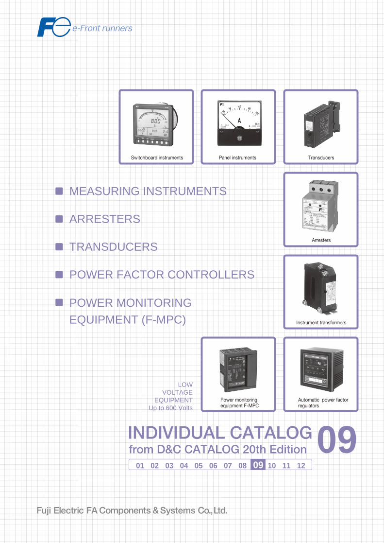
MEASURING INSTRUMENTS
POWER MONITORING EQUIPMENT (F-MPC)
TRANSDUCERS
POWER FACTOR CONTROLLERS
ARRESTERS
Panel instruments Transducers
Arresters
Instrument transformers
Automatic power factorregulators
Switchboard instruments
Power monitoringequipment F-MPC
2010-09 PDF FOLS DEC2009

Ha Noi Oce:No. 95 - TT4, My Dinh Urban Area, My Dinh, Nam Tu Liem, Hanoi.Tel: (84 4) 3568 3740Fax: (84 4) 3568 3741
Cambodia Oce:#140, Room 1-B, St430, Sangkat Toul Tompuong II, Khan Chamkamon, PP.Tel: 855 2322 3635Fax: 855 2322 3645
Head Oce:No 88, Vinh Phu 40, Hoa Long,Vinh Phu, Thuan An, Binh Duong.Tel: (84 650) 37 37 619Fax: (84 650) 37 37 620
1800 6547THINK TOGETHER
Nhà phân phối thiết bị điện công nghiệphàng đầu Việt Nam
T
09Switchboard Instruments WM8N type ................................................................................................... 09/1
Power line multi-meters WE1MA................................................................. 09/10
F type ............................................................................................................. 09/23
C series .......................................................................................................... 09/32WF series ....................................................................................................... 09/39WH7 series .................................................................................................... 09/43WT2AC .......................................................................................................... 09/55
CN232, 233 .................................................................................................... 09/57CN226 ............................................................................................................ 09/60CN227 ............................................................................................................ 09/62CN2340, 2341 ................................................................................................ 09/70
General information ..................................................................................... 09/71Through-type CT/CC3L ................................................................................. 09/72CT with primary winding/CC3P .................................................................... 09/75Through type CT/CC3M ................................................................................ 09/77Split type CT/CC2 .......................................................................................... 09/82Voltage transformers/CD32, 34 .................................................................... 09/84Optional accessories ..................................................................................... 09/85
Automatic power factor regulator QC06E and QC12E ................................ 09/86
General information ..................................................................................... 09/102Multiple function protectors and controllers F-MPC60B, F-MPC30 ................................................................................ 09/103Power monitoring unit F-MPC04, F-MPC04P, F-MPC04S ............................................................. 09/118MCCB with ZCT and zero-phase CT ............................................................. 09/132Current transformers CC2............................................................................. 09/134Terminal relay RS16.................................................................................... 09/137Connector terminal-block AU-CW21B1...................................................... 09/138
Page
Transducers
Measuring Instruments, Transducers
Arresters, Power Factor Controllers
Power Monitoring Equipment
Arresters (Surge protective devices)
Panel Instruments
Instrument Transformers
Power Factor Controllers
Power Monitoring Equipment
MINIMUM ORDERS
Orders amounting to less than ¥10,000 net per order willbe charged as ¥10,000 net per order plus freight andother charges.
WEIGHTS AND DIMENSIONS
Weights and dimensions appearing in this catalog are thebest information available at the time of going to press.FUJI ELECTRIC FA has a policy of continuous productimprovement, and design changes may make thisinformation out of date.Please confirm such details before planning actualconstruction.
INFORMATION IN THIS CATALOG IS SUBJECT TO
CHANGE WITHOUT NOTICE.
Fuji Electric FA Components & Systems Co., Ltd./D & C CatalogInformation subject to change without notice 09/1
09
Switchboard InstrumentsWM8N type
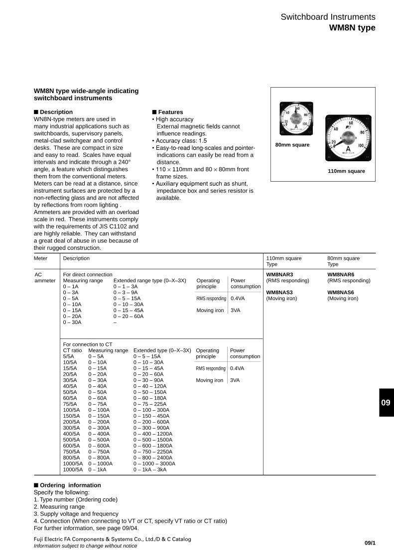
WM8N type wide-angle indicatingswitchboard instruments
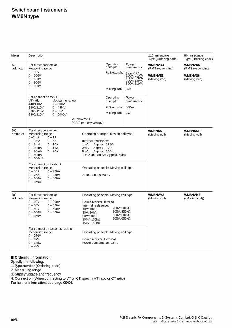
DescriptionWN8N-type meters are used in many industrial applications such as switchboards, supervisory panels, metal-clad switchgear and control desks. These are compact in size and easy to read. Scales have equal intervals and indicate through a 240° angle, a feature which distinguishes them from the conventional meters. Meters can be read at a distance, since instrument surfaces are protected by a non-reflecting glass and are not affected by reflections from room lighting . Ammeters are provided with an overload scale in red. These instruments comply with the requirements of JIS C1102 and are highly reliable. They can withstand a great deal of abuse in use because of their rugged construction.
Features• High accuracy External magnetic fields cannot
influence readings.• Accuracy class: 1.5• Easy-to-read long-scales and pointer-
indications can easily be read from a distance.
• 110 × 110mm and 80 × 80mm front frame sizes.
• Auxiliary equipment such as shunt, impedance box and series resistor is available.
80mm square
110mm square
Ordering informationSpecify the following:1. Type number (Ordering code)2. Measuring range 3. Supply voltage and frequency4. Connection (When connecting to VT or CT, specify VT ratio or CT ratio)For further information, see page 09/04.
Meter Description 110mm squareType
80mm squareType
ACammeter
For direct connectionMeasuring range 0 – 1A0 – 3A0 – 5A0 – 10A0 – 15A 0 – 20A0 – 30A
Extended range type (0–X–3X)0 – 1 – 3A0 – 3 – 9A0 – 5 – 15A0 – 10 – 30A0 – 15 – 45A0 – 20 – 60A–
Operating principle
RMS responding
Moving iron
WM8NAR3(RMS responding)
WM8NAS3(Moving iron)
WM8NAR6(RMS responding)
WM8NAS6(Moving iron)
For connection to CTCT ratio 5/5A10/5A15/5A20/5A30/5A40/5A50/5A60/5A75/5A100/5A150/5A200/5A300/5A400/5A500/5A600/5A750/5A800/5A1000/5A1000/5A
Measuring range0 – 5A0 – 10A0 – 15A0 – 20A0 – 30A0 – 40A0 – 50A 0 – 60A0 – 75A0 – 100A0 – 150A0 – 200A0 – 300A0 – 400A0 – 500A0 – 600A0 – 750A0 – 800A0 – 1000A0 – 1kA
Extended type (0–X–3X)0 – 5 – 15A0 – 10 – 30A0 – 15 – 45A0 – 20 – 60A0 – 30 – 90A0 – 40 – 120A0 – 50 – 150A 0 – 60 – 180A0 – 75 – 225A0 – 100 – 300A0 – 150 – 450A0 – 200 – 600A0 – 300 – 900A0 – 400 – 1200A0 – 500 – 1500A0 – 600 – 1800A0 – 750 – 2250A0 – 800 – 2400A0 – 1000 – 3000A0 – 1kA – 3kA
Power consumption
0.4VA
3VA
Operating principle
RMS responding
Moving iron
Power consumption
0.4VA
3VA
Fuji Electric FA Components & Systems Co., Ltd./D & C CatalogInformation subject to change without notice09/2
Switchboard InstrumentsWM8N type
Meter Description 110mm squareType (Ordering code)
80mm squareType (Ordering code)
ACvoltmeter
DCvoltmeter
For direct connectionMeasuring range 0 – 50V0 – 100V0 – 150V0 – 300V0 – 600V
WM8NVR3(RMS responding)
WM8NVS3(Moving iron)
WM8NVR6(RMS responding)
WM8NVS6(Moving iron)
WM8NAM3(Moving coil)
WM8NAM6(Moving coil)
DCammeter
For direct connectionMeasuring range 0 –1mA0 – 3mA 0 – 5mA0 – 10mA0 – 30mA0 – 50mA0 – 100mA
0 – 1A0 – 5A0 – 10A0 – 15A0 – 30A
0 – 200A0 – 250A 0 – 500A
Operating principle: Moving coil type
Internal resistance:1mA: Approx. 185Ω3mA: Approx. 17Ω5mA: Approx. 10Ω 10mA and above: Approx. 50mV
For connection to VTVT ratio 440/110V3300/110V6600/110V6600/110V
Measuring range0 – 600V0 – 4.5kV0 – 9kV0 – 9000V
VT ratio: Y/110(Y: VT primary voltage)
For connection to shuntMeasuring range0 – 50A 0 – 75A 0 – 100A 0 – 150A
Operating principle: Moving coil type
Shunt ratings: 60mV
For connection to series resistorMeasuring range0 – 750V 0 – 1kV0 – 1.5kV0 – 2kV
Operating principle: Moving coil type
Series resister: ExternalPower consumption: 1mA
0 – 200V 0 – 300V0 – 500V0 – 600V
For direct connectionMeasuring range0 – 10V 0 – 30V 0 – 50V 0 – 100V0 – 150V
Operating principle: Moving coil type
Series resister: InternalInternal resistance:10V: 10kΩ30V: 30kΩ50V: 50kΩ100V: 100kΩ150V: 150kΩ
WM8NVM3(Moving coil)
WM8NVM6((Moving coil))
Operating principle
RMS responding
Moving iron
Power consumption
50V: 0.1V100V: 0.1VA150V: 0.9VA300V: 1.8VA600V: 1.2VA
8VA
Operating principle
RMS responding
Moving iron
Power consumption
0.9VA
8VA
200V: 200kΩ300V: 300kΩ500V: 500kΩ600V: 600kΩ
Ordering informationSpecify the following:1. Type number (Ordering code)2. Measuring range 3. Supply voltage and frequency4. Connection (When connecting to VT or CT, specify VT ratio or CT ratio)For further information, see page 09/04.
Fuji Electric FA Components & Systems Co., Ltd./D & C CatalogInformation subject to change without notice 09/3
09
Switchboard InstrumentsWM8N type
Meter Description 110mm squareType
80mm squareType
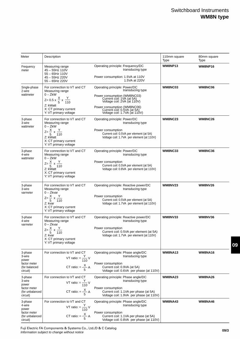
Frequencymeter
Measuring range45 – 55Hz 110V55 – 65Hz 110V45 – 55Hz 220V55 – 65Hz 220V
Operating principle: Frequency/DCtransducing type
Power consumption: 1.5VA at 110V1.5VA at 220V
WM8NP13 WM8NP16
Single-phase2-wirewattmeter
For connection to VT and CT Measuring range0 – ZkW
Z= 0.5 x x
Z: kWattX: CT primary current Y: VT primary voltage
Operating principle: Power/DCtransducing type
Power consumption (WM8NC03)Current coil: 1VA (at 5A)Voltage coil: 2VA (at 110V)
Power consumption (WM8NC06)Current coil: 0.5VA (at 5A)Voltage coil: 1.7VA (at 110V)
WM8NC03 WM8NC06
3-phase3-wirewattmeter
For connection to VT and CT Measuring range0 – ZkW
Z= x
Z: kWattX: CT primary current Y: VT primary voltage
Operating principle: Power/DCtransducing type
Power consumptionCurrent coil: 0.5VA per element (at 5A)Voltage coil: 1.7VA per element (at 110V)
WM8NC23 WM8NC26
3-phase4-wirewattmeter
For connection to VT and CT Measuring range0 – ZkW
Z= x
Z: kWattX: CT primary current Y: VT primary voltage
Operating principle: Power/DCtransducing type
Power consumptionCurrent coil: 0.5VA per element (at 5A)Voltage coil: 0.8VA per element (at 110V)
WM8NC33 WM8NC36
X5
Y110
X5
Y110
X5
Y110
X5
Y110
3-phase3-wirevarmeter
For connection to VT and CT Measuring range0 – Zkvar
Z= x
Z: kvarX: CT primary current Y: VT primary voltage
Operating principle: Reactive power/DCtransducing type
Power consumptionCurrent coil: 0.5VA per element (at 5A)Voltage coil: 1.7VA per element (at 110V)
WM8NV23 WM8NV26
X5
Y110
3-phase4-wirevarmeter
For connection to VT and CT Measuring range0 – Zkvar
Z= x
Z: kvarX: CT primary current Y: VT primary voltage
Operating principle: Reactive power/DCtransducing type
Power consumptionCurrent coil: 0.5VA per element (at 5A)Voltage coil: 1.7VA per element (at 110V)
WM8NV33 WM8NV36
3-phase3-wirepowerfactor meter(for balanced circuit)
For connection to VT and CT VT ratio: =
CT ratio: =
Operating principle: Phase angle/DCtransducing type
Power consumptionCurrent coil: 0.9VA (at 5A)Voltage coil: 0.6VA per phase (at 110V)
WM8NA13 WM8NA16 Y110
V
X 5
A
3-phase3-wirepowerfactor meter(for unbalanced circuit)
For connection to VT and CT VT ratio: =
CT ratio: =
Operating principle: Phase angle/DCtransducing type
Power consumptionCurrent coil: 1.1VA per phase (at 5A)Voltage coil: 1.9VA per phase (at 110V)
WM8NA23 WM8NA26 Y110
V
X 5
A
3-phase4-wirepowerfactor meter(for unbalanced circuit)
For connection to VT and CT VT ratio: =
CT ratio: =
Operating principle: Phase angle/DCtransducing type
Power consumptionCurrent coil: 1.1VA per phase (at 5A)Voltage coil: 0.8VA per phase (at 110V)
WM8NA43 WM8NA46 Y110
V
X 5
A
Fuji Electric FA Components & Systems Co., Ltd./D & C CatalogInformation subject to change without notice09/4
Switchboard InstrumentsWM8N type
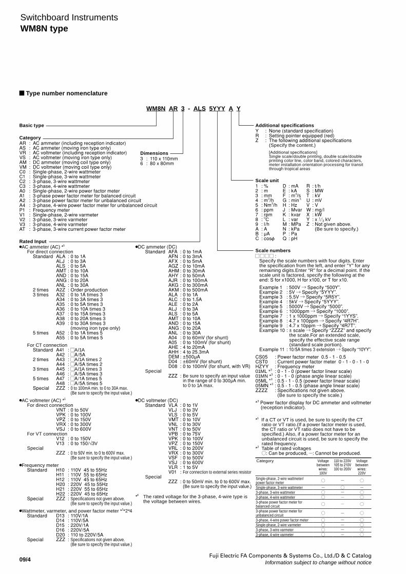
Type number nomenclature
WM8N AR 3 - ALS 5YYY A Y
Basic type
CategoryAR : AC ammeter (including reception indicator)AS : AC ammeter (moving iron type only)VR : AC voltmeter (including reception indicator)VS : AC voltmeter (moving iron type only)AM : DC ammeter (moving coil type only)VM : DC voltmeter (moving coil type only)C0 : Single-phase, 2-wire wattmeterC1 : Single-phase, 3-wire wattmeterC2 : 3-phase, 3-wire wattmeterC3 : 3-phase, 4-wire wattmeterA0 : Single-phase, 2-wire power factor meterA1 : 3-phase power factor meter for balanced circuitA2 : 3-phase power factor meter for unbalanced circuitA4 : 3-phase, 4-wire power factor meter for unbalanced circuitP1 : Frequency meterV1 : Single-phase, 2-wire varmeterV2 : 3-phase, 3-wire varmeterV3 : 3-phase, 4-wire varmeterAT : 3-phase, 3-wire current power factor meter
Additional specifications Y : None (standard specification) R : Setting pointer equipped (red) Z : The following additional specifications (Specify the content.)
[Additional specifications]Single scale/double printing, double scale/double printing color line, color band, colored characters, meter installation orientation processing for transit through tropical areas
Scale unit1 : %2 : m3 : mm4 : m3/h5 : Nm3/h6 : ppm7 : rpm8 : oC9 : l/hA : AB : µAC : cos
D : mAE : kAF : m3/sG : min-1
H : HzJ : MvarK : kvarL : varM : MPaN : kPaP : PaQ : pH
R : t/hS : MWT : kVU : mVV : VW : mg/lX : kWY : x kVZ : Not given above. (Be sure to specify.)
Scale numbers :
Specify the scale numbers with four digits. Enter the specification from the left, and enter "Y" for any remaining digits.Enter "R" for a decimal point. If the scale unit is factored, specify the following at the end: S for x1000, H for x100, or T for x10.
Example 1 : 500V Specify “500Y”.Example 2 : 5V Specify “5YYY”.Example 3 : 5.5V Specify “5R5Y”.Example 4 : 5kV Specify “5YYY”.Example 5 : 5000V Specify “5000”.Example 6 : 1000ppm Specify “1000”.Example 7 : 1 x 1000ppm Specify “1YYS”.Example 8 : 4.7 x 100ppm Specify “4R7H”.Example 9 : 4.7 x 10ppm Specify “4R7T”.Example 10 : ± scale Specify “ZZZZ” and specify
the scale.For an extended scale, specify the effective scale range (standard scale portion).
Example 11 : 10/5A times 3 extension Specify “10YY”.
CS05 : Power factor meter 0.5 - 1 - 0.5CST0 : Current power factor meter 0 - 1 - 0 - 1 - 0HZYY : Frequency meter01ML *3 : 0 - 1 - 0 (power factor linear scale)01MN *3 : 0 - 1 - 0 (phase angle linear scale)05ML *3 : 0.5 - 1 - 0.5 (power factor linear scale)05MN *3 : 0.5 - 1 - 0.5 (phase angle linear scale)ZZZZ : Specifications not given above. (Be sure to specify the scale.)
*3 Power factor display for DC ammeter and voltmeter (reception indicator).
*1 If a CT or VT is used, be sure to specify the CT ratio or VT ratio.(If a power factor meter is used, the CT ratio or VT ratio does not have to be specified.) Also, if a power factor meter for an unbalanced circuit is used, be sure to specify the rated frequency.
*2 Table of rated voltages : Can be produced, : Cannot be produced.
Category Voltagebetween
wires: 100V
110 to 220V105 to 210V100 to 200V
Voltagebetween
wires: 220V
Single-phase, 2-wire wattmeter/power factor meterSingle-phase, 3-wire wattmeter3-phase, 3-wire wattmeter3-phase, 4-wire wattmeter3-phase power factor meter for balanced circuit3-phase power factor meter for unbalanced circuit3-phase, 4-wire power factor meterSingle-phase, 2-wire varmeter3-phase, 3-wire varmeter3-phase, 4-wire varmeter
Rated InputAC ammeter (AC) *1
For direct connection Standard ALA : 0 to 1A ALJ : 0 to 3A ALS : 0 to 5A AMT : 0 to 10A AND : 0 to 15A ANG : 0 to 20A ANL : 0 to 30A 2 times A2Z : Order production 3 times A32 : 0 to 1A times 3 A34 : 0 to 3A times 3 A35 : 0 to 5A times 3 A36 : 0 to 10A times 3 A37 : 0 to 15A times 3 A38 : 0 to 20A times 3 A39 : 0 to 30A times 3 (moving iron type only) 5 times A52 : 0 to 1A times 5 A55 : 0 to 5A times 5
For CT connection Standard A41 : A/1A A42 : A/5A 2 times A43 : A/1A times 2 A44 : A/5A times 2 3 times A45 : A/1A times 3 A46 : A/5A times 3 5 times A47 : A/1A times 5 A48 : A/5A times 5 Special ZZZ : 0 to 100mA min. to 0 to 30A max. (Be sure to specify the input value.)
AC voltmeter (AC) *1
For direct connection VNT : 0 to 50V VPK : 0 to 100V VPZ : 0 to 150V VRX : 0 to 300V VSJ : 0 to 600V For VT connection V12 : 0 to 150V V13 : 0 to 150/√3V Special ZZZ : 0 to 50V min. to 0 to 600V max. (Be sure to specify the input value.)
Frequency meter Standard H10 : 110V 45 to 55Hz H11 : 110V 55 to 65Hz H12 : 110V 45 to 65Hz H20 : 220V 45 to 55Hz H21 : 220V 55 to 65Hz H22 : 220V 45 to 65Hz Special ZZZ : Specifications not given above. (Be sure to specify the input value.)
Wattmeter, varmeter, and power factor meter *1*2*4 Standard D13 : 110V/1A D14 : 110V/5A D15 : 220V/1A D16 : 220V/5A D20 : 110 to 220V/5A Special ZZZ : Specifications not given above. (Be sure to specify the input value.)
DC ammeter (DC) Standard AFA : 0 to 1mA AFN : 0 to 3mA AFX : 0 to 5mA AGZ : 0 to 10mA AHM : 0 to 30mA AHY : 0 to 50mA AJR : 0 to 100mA AKG : 0 to 300mA AKM : 0 to 500mA ALA : 0 to 1A ALC : 0 to 1.5A ALE : 0 to 2A ALJ : 0 to 3A ALS : 0 to 5A AMT : 0 to 10A AND : 0 to 15A ANG : 0 to 20A ANL : 0 to 30A A04 : 0 to 60mV (for shunt) A05 : 0 to 100mV (for shunt) AHE : 4 to 20mA AHH : 4 to 25.3mA DEM : ±500µA D04 : ±60mV (for shunt) D08 : 0 to 100mV (for shunt, with VR) Special ZZZ : Be sure to specify an input value in the range of 0 to 300µA min. to 0 to 1A max.
DC voltmeter (DC) Standard VLA : 0 to 1V VLJ : 0 to 3V VLS : 0 to 5V VMT : 0 to 10V VNL : 0 to 30V VNT : 0 to 50V VPB : 0 to 75V VPK : 0 to 100V VPZ : 0 to 150V VRL : 0 to 200V VRX : 0 to 300V VSF : 0 to 500V VSJ : 0 to 600V VLR : 1 to 5V V01 : For connection to external series resistor Special ZZZ : 0 to 50mV min. to 0 to 600V max. (Be sure to specify the input value.)
*4 The rated voltage for the 3-phase, 4-wire type is the voltage between wires.
Dimensions3 : 110 x 110mm6 : 80 x 80mm
Fuji Electric FA Components & Systems Co., Ltd./D & C CatalogInformation subject to change without notice 09/5
09
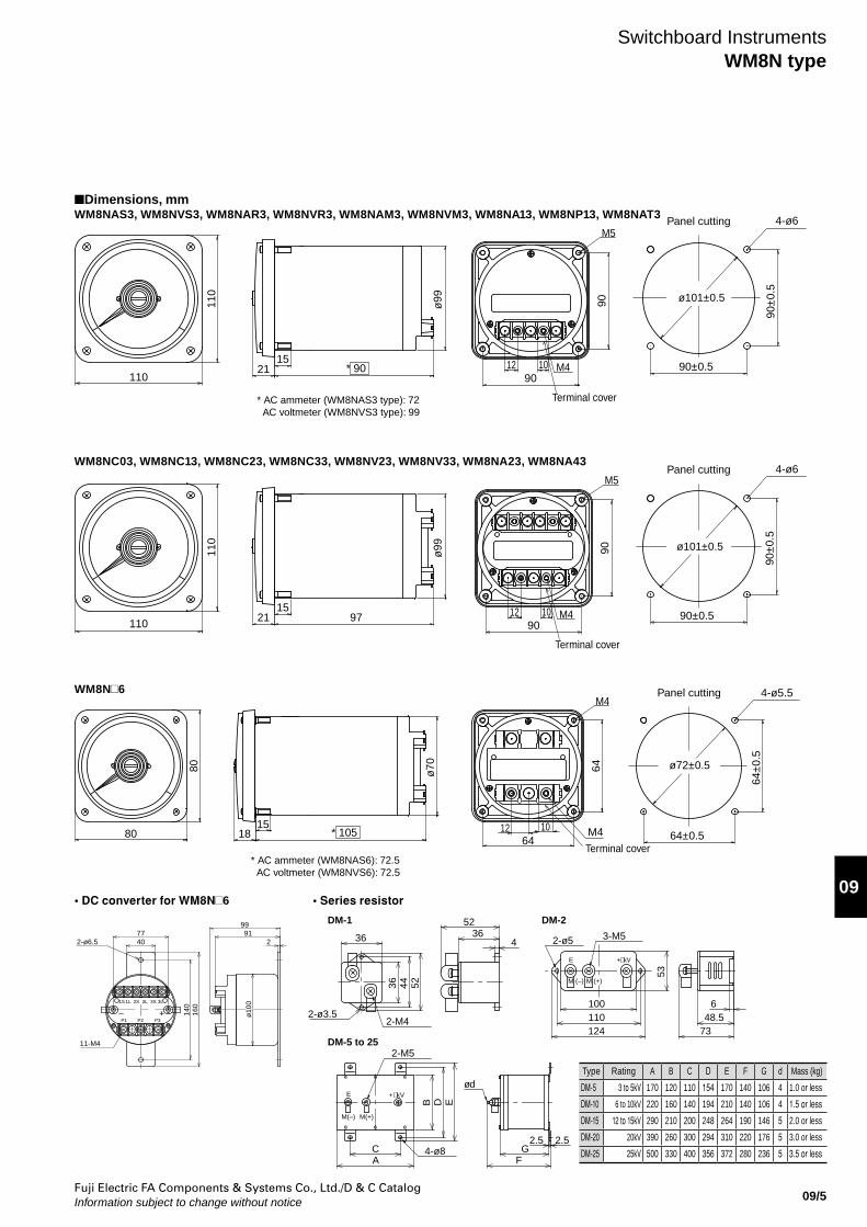
Dimensions, mmWM8NAS3, WM8NVS3, WM8NAR3, WM8NVR3, WM8NAM3, WM8NVM3, WM8NA13, WM8NP13, WM8NAT3
Switchboard InstrumentsWM8N type
WM8N 6
WM8NC03, WM8NC13, WM8NC23, WM8NC33, WM8NV23, WM8NV33, WM8NA23, WM8NA43
Panel cutting
90±0.5
90±0.5
90±
0.5
90±
0.5
Panel cutting
21
ø9911
0
110
15
Terminal cover
M4
M5
90
12 1090
Terminal cover
M4
M5
9012 10
90
4-ø6
21
ø9911
0
110
1597
4-ø6
* 90
ø101±0.5
ø101±0.5
* AC ammeter (WM8NAS3 type): 72 AC voltmeter (WM8NVS3 type): 99
Terminal cover
M4Panel cutting
64±0.5
64±
0.5
M418
64ø7080
8015
* 10564
4-ø5.5
ø72±0.5
12 10
* AC ammeter (WM8NAS6): 72.5 AC voltmeter (WM8NVS6): 72.5
Type Rating A B C D E F G d Mass (kg)
DM-5 3 to 5kV 170 120 110 154 170 140 106 4 1.0 or less
DM-10 6 to 10kV 220 160 140 194 210 140 106 4 1.5 or less
DM-15 12 to 15kV 290 210 200 248 264 190 146 5 2.0 or less
DM-20 20kV 390 260 300 294 310 220 176 5 3.0 or less
DM-25 25kV 500 330 400 356 372 280 236 5 3.5 or less
• DC converter for WM8N 6 • Series resistor
ø10
0
160
140
77 9140 2
11-M4
2-ø6.5
3L
P3
2S
P1 P2
1S 1L 2L 3S
99
– +
DM-5 to 25
DM-1 DM-2
7348.52-M4
4-ø8
ED
2-M5
B
CA
36 5244
2-ø3.5
36
GF
ød
2.5 2.5
2-ø5
100110124
5236
43-M5
53
6
M(+)M(–)
E + kV
M (–) M (+)
E + kV
Fuji Electric FA Components & Systems Co., Ltd./D & C CatalogInformation subject to change without notice09/6
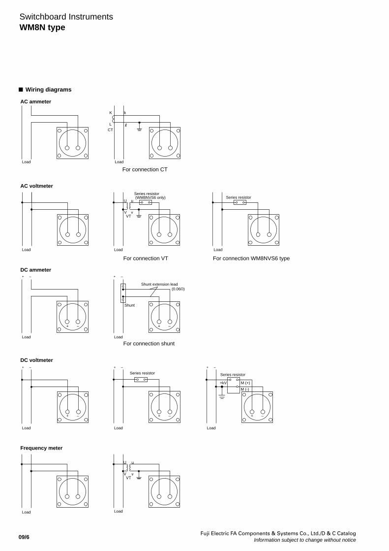
Wiring diagrams
Switchboard InstrumentsWM8N type
Load
Load Load
Load
Load Load
Load Load
Load
Load
Load
Load
K k
L CT
AC ammeter
DC ammeter
DC voltmeter
Frequency meter
AC voltmeter
For connection CT
For connection VT
For connection shunt
For connection WM8NVS6 type
U u
V vVT
Series resistor
Series resistor
Series resistor (WM8NVS6 only)
Shunt
Shunt extension lead(0.06Ω)
+ –
+ –
+ –
+ –
+ –
+ –
+ –
+ –
+ –
+ –
+kV
Series resistor
M (+)
M (-)
U u
V vVT
Fuji Electric FA Components & Systems Co., Ltd./D & C CatalogInformation subject to change without notice 09/7
09
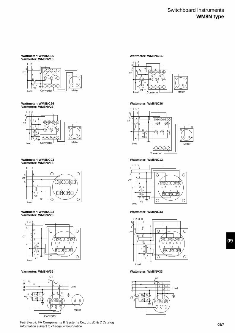
Switchboard InstrumentsWM8N type
Wattmeter: WM8NC06Varmerter: WM8NV16
Wattmeter: WM8NC26Varmerter: WM8NV26
Wattmeter: WM8NC36
Wattmeter: WM8NC03Varmerter: WM8NV13
Wattmeter: WM8NC13
Wattmeter: WM8NC23Varmerter: WM8NV23
Wattmeter: WM8NC33
Varmerter: WM8NV36 Wattmeter: WM8NV33
Wattmeter: WM8NC16
Load
Load
Load
Load
Load
Load
1 2
VT
K k
L
U u
V v
CT
Converter
Converter
Converter
Converter
Converter
Load
Load
LoadLoad
1S 1L
P1 P2
+ –
1S 1L 3S 3L
P3P2P1
1 2 3
VT
K k
L K k
L U u
V vU u
V v
CT
+ −
1 2 3
1 2 3
1 2 3 0
−+
−+
−+
−+
VT
K k
L K k
L U uV v
U uV v
CT
P1 P2 P3
1S 1L 3S 3L
+ −
VT
1L 2S 2L1S1
2 10 6
3 8 9 5 7
P3P1 P0
3S 3L
K k
LK k
LK k
LU u
V v
U u
V v
1 2 3 0
CT
1S 1L 3S 3L
P3P0P1
2S 2L
K k
L K k
L K k
LU uV vU u
CT
+ −
1 2
5
7
A B C D
8 9
6
3 4
K k
LK k
L
U u
V v
U u
V v
CT
V1
1S1 3 5
2 4 6
71L 3S 3L
P3P2P1
K k
L
U u
V v
1 2
CT
VT
1S
P1
1 2
3 4P2
1L1
1 2
5
7
A B C D
8 9
6
3 4 1 2
5
7
A B C D
8 9
6
3 4
1 2
5
7
A B C D
8 9
6
3 4
1 2 3K k
LK k
L
U u
V v
U u
V v
CT
VT
P1 P2 P3
3L3S1L1S1 3 5 7
642
3
VTu v
0
U V
uvu v
UVU V
P2P1 P3+
3S–1L1S 2S 2L
k
3L
l
12 K
CT
kK
kl K
lL
L
L
+ –
0
u
UVT
u v uv
U V UV
2S
P2
v
P1
1L1S
V
P3
3L2L 3S
23
1K L
kk l K
CT
lkK
LLl
Meter Meter
Meter
Meter
Meter
Fuji Electric FA Components & Systems Co., Ltd./D & C CatalogInformation subject to change without notice09/8
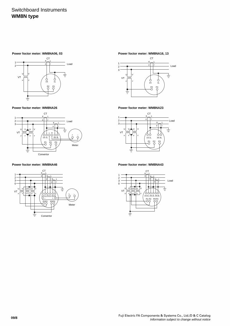
Switchboard InstrumentsWM8N type
Power foctor meter: WM8NA06, 03 Power foctor meter: WM8NA16, 13
Power foctor meter: WM8NA26 Power foctor meter: WM8NA23
Power foctor meter: WM8NA46 Power foctor meter: WM8NA43
K L
VTu
U
21
1S 1L
P2 P1
v
V
k l LoadLoad
CTK L
VTu
U
23
1
1S 1L
P2 P3
v
V
k l
CT
Load
Load
lk
P3
VTvu
32
U V
P2P1
u v
VU
–
1S 1L 3S
+
k
K
3L
l
L
–+
1
CTK L
Convertor
Convertor
Meter
Meter
1 LK
P3
3S
VTu v
U V
23
1S 1L
P1 P2
u
U
v
V
k l
K
k
3L
LoadL
l
CT
0
P3
U
u
U
VTu
V
v
V U
v u
V
v2S
P2P1
1S1L–
P0
2L3S+
3L
1
32
K
k
k l
l K
k
L
CTK L
L
l
+ –
P3
vu
U V
vu v u
P2
2S
P1
1L1S
P0
2L 3S
UVU V
Kk
k
l
Kk
lL
3L
Ll
K L1
0
VT
32
CT
Fuji Electric FA Components & Systems Co., Ltd./D & C CatalogInformation subject to change without notice 09/9
09
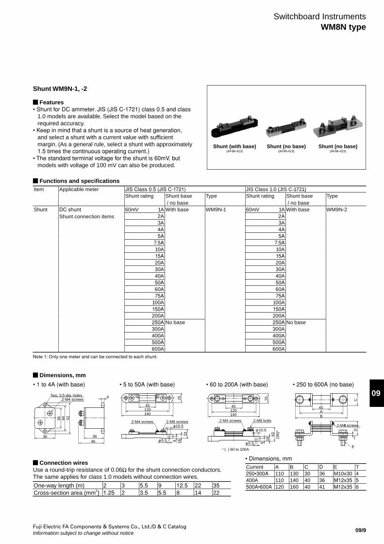
Shunt WM9N-1, -2
Features• Shunt for DC ammeter. JIS (JIS C-1721) class 0.5 and class
1.0 models are available. Select the model based on the required accuracy.
• Keep in mind that a shunt is a source of heat generation, and select a shunt with a current value with sufficient margin. (As a general rule, select a shunt with approximately 1.5 times the continuous operating current.)
• The standard terminal voltage for the shunt is 60mV, but models with voltage of 100 mV can also be produced.
Connection wiresUse a round-trip resistance of 0.06Ω for the shunt connection conductors.The same applies for class 1.0 models without connection wires.
One-way length (m) 2 3 5.5 9 12.5 22 35Cross-section area (mm2) 1.25 2 3.5 5.5 8 14 22
• 1 to 4A (with base) • 5 to 50A (with base) • 60 to 200A (with base) • 250 to 600A (no base)
• Dimensions, mmCurrent A B C D E T250•300A 110 130 30 36 M10x30 4400A 110 140 40 36 M12x35 5500A•600A 120 160 40 41 M12x35 6
Functions and specificationsItem Applicable meter JIS Class 0.5 (JIS C-1721) JIS Class 1.0 (JIS C-1721)
Shunt rating Shunt base / no base
Type Shunt rating Shunt base / no base
Type
Shunt DC shuntShunt connection items
60mV 1A With base WM9N-1 60mV 1A With base WM9N-22A 2A3A 3A4A 4A5A 5A
7.5A 7.5A10A 10A15A 15A20A 20A30A 30A40A 40A50A 50A60A 60A75A 75A
100A 100A150A 150A200A 200A250A No base 250A No base300A 300A400A 400A500A 500A600A 600A
Note 1: Only one meter and can be connected to each shunt.
Shunt (with base)(AF96-423)
Shunt (no base)(AF96-423)
Shunt (no base)(AF96-423)
Dimensions, mm
36 44 52
Two, 3.5-dia. holes2-M4 screws
36 3646
4
45120140
2-M6 screws2-M4 screws
256 18
33
5.5
10.5
45120140
2-M8 bolts2-M4 screws
256
1843
(36)
*
5.5
10.5
* ( ) 60 to 100A
45AB
E
T
2-M4 screws4
DC
Switchboard InstrumentsWM8N type
Fuji Electric FA Components & Systems Co., Ltd./D & C CatalogInformation subject to change without notice09/10
Switchboard InstrumentsPower line multi-meters
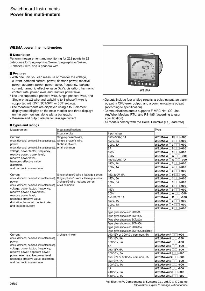
WE1MA power line multi-meters
DescriptionPerform measurement and monitoring for 213 points in 52 categories for Single-phase/2-wire, Single-phase/3-wire, 3-phase/3-wire, and 3-phase/4-wire
Features• With one unit, you can measure or monitor the voltage,
current, demand current, power, demand power, reactive power, apparent power, power factor, frequency, leakage current, harmonic effective value (A,V), distortion, harmonic content rate, power level, and reactive power level.
• The unit supports 3-phase/3-wire, Single-phase/3-wire, and Single-phase/2-wire and switching to 3-phase/4-wire is supported with 2VT, 3CT/3VT, or 3CT settings.
• The measurements are displayed using a four-element display: one display on the main monitor and three displays on the sub-monitors along with a bar graph.
• Measure and output alarms for leakage current.
Types and ratingsMeasurement Input specifications Type
Input circuits Input rangeCurrent (max. demand, demand, instantaneous), power (max. demand, demand, instantaneous), voltage, power factor, frequency, reactive power, power level, reactive power level, harmonic effective value, distortion, and harmonic content rate
Single-phase/2-wire, Single-phase/3-wire, 3-phase/3-wire or all common
150V/300V, 5A WE1MA-A F -000150V, 5A WE1MA-A 1 -000300V, 5A WE1MA-A 3 -0005A WE1MA-A 5 -000150V WE1MA-A 9 -000300V WE1MA-A A -000150V/300V, 1A WE1MA-A G -000150V, 1A WE1MA-A 2 -000300V, 1A WE1MA-A 4 -0001A WE1MA-A 6 -000
Current (max. demand, demand, instantaneous), power (max. demand, demand, instantaneous), voltage, power factor, frequency, reactive power, power level, reactive power level, harmonic effective value, distortion, harmonic content rate, and leakage current
Single-phase/2-wire + leakage current, Single-phase/3-wire + leakage current3-phase/3-wire+leakege current or all common
150/300V, 5A WE1MA-A F -000150V, 5A WE1MA-A 1 -000300V, 5A WE1MA-A 3 -0005A WE1MA-A 5 -000150V WE1MA-A 9 -000300V WE1MA-A A -000150/300V, 1A WE1MA-A G -000150V, 1A WE1MA-A 2 -000300V, 1A WE1MA-A 4 -0001A WE1MA-A 6 -000Type given above and ZCT50AType given above and ZCT100AType given above and ZCT200AType given above and ZCT400AType given above and ZCT600AType given above and ZCT100A (outdoor)
Current (max. demand, demand, instantaneous), power (max. demand, demand, instantaneous), voltage, power factor, frequency, reactive power, apparent power, power level, reactive power level, harmonic effective value, distortion, and harmonic content rate
3-phase, 4-wire 150/√3V or 300/√3V common, 5A WE1MA-A4F -000150/√3V, 5A WE1MA-A41 -000300/√3V, 5A WE1MA-A43 -0005A WE1MA-A45 -000150/√3V, 5A WE1MA-A49 -000300/√3V, 5A WE1MA-A4A -000150/√3V or 300/√3V common, 1A WE1MA-A4G -000150/√3V, 1A WE1MA-A42 -000300/√3V, 1A WE1MA-A44 -0001A WE1MA-A46 -000440/√3V, 5A WE1MA-A4B -000440/√3V, 1A WE1MA-A4C -000
WE1MA
• Outputs include four analog circuits, a pulse output, an alarm output, a CPU error output, and a communications output (according to specification).
• Communications output supports F-MPC Net, CC-Link, AnyWire, Modbus RTU, and RS-485 (according to user specification).
• All models comply with the RoHS Directive (i.e., lead-free).
Fuji Electric FA Components & Systems Co., Ltd./D & C CatalogInformation subject to change without notice 09/11
09
Switchboard InstrumentsPower line multi-meters
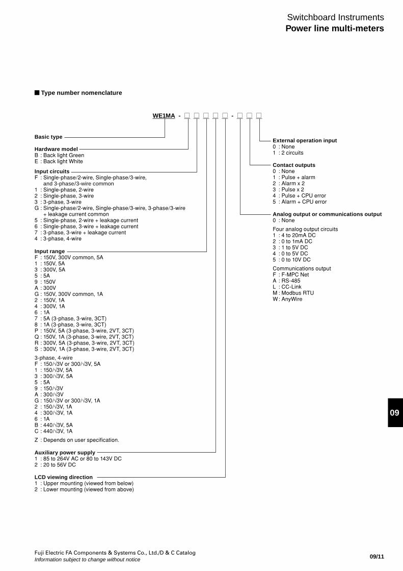
Type number nomenclature
WE1MA - -
Basic type
Hardware modelB : Back light GreenE : Back light White
Input circuitsF : Single-phase/2-wire, Single-phase/3-wire, and 3-phase/3-wire common1 : Single-phase, 2-wire2 : Single-phase, 3-wire3 : 3-phase, 3-wireG : Single-phase/2-wire, Single-phase/3-wire, 3-phase/3-wire + leakage current common5 : Single-phase, 2-wire + leakage current6 : Single-phase, 3-wire + leakage current7 : 3-phase, 3-wire + leakage current4 : 3-phase, 4-wire
Auxiliary power supply1 : 85 to 264V AC or 80 to 143V DC2 : 20 to 56V DC
Analog output or communications output0 : None
Four analog output circuits1 : 4 to 20mA DC2 : 0 to 1mA DC3 : 1 to 5V DC4 : 0 to 5V DC5 : 0 to 10V DC
Communications outputF : F-MPC NetA : RS-485L : CC-LinkM : Modbus RTUW : AnyWire
Contact outputs0 : None1 : Pulse + alarm2 : Alarm x 23 : Pulse x 24 : Pulse + CPU error5 : Alarm + CPU error
External operation input0 : None1 : 2 circuits
LCD viewing direction1 : Upper mounting (viewed from below)2 : Lower mounting (viewed from above)
Input rangeF : 150V, 300V common, 5A1 : 150V, 5A3 : 300V, 5A5 : 5A9 : 150VA : 300VG : 150V, 300V common, 1A2 : 150V, 1A4 : 300V, 1A6 : 1A7 : 5A (3-phase, 3-wire, 3CT)8 : 1A (3-phase, 3-wire, 3CT)P : 150V, 5A (3-phase, 3-wire, 2VT, 3CT)Q : 150V, 1A (3-phase, 3-wire, 2VT, 3CT)R : 300V, 5A (3-phase, 3-wire, 2VT, 3CT)S : 300V, 1A (3-phase, 3-wire, 2VT, 3CT)
3-phase, 4-wireF : 150/√3V or 300/√3V, 5A1 : 150/√3V, 5A3 : 300/√3V, 5A5 : 5A9 : 150/√3VA : 300/√3VG : 150/√3V or 300/√3V, 1A2 : 150/√3V, 1A4 : 300/√3V, 1A6 : 1AB : 440/√3V, 5AC : 440/√3V, 1A
Z : Depends on user specification.
Fuji Electric FA Components & Systems Co., Ltd./D & C CatalogInformation subject to change without notice09/12
Switchboard InstrumentsPower line multi-meters
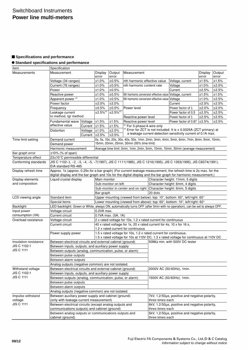
Specifications and performance
Standard specifications and performanceItem SpecificationMeasurements Measurement Display
errorOutputerror
Measurement Displayerror
Outputerror
Voltage (34 ranges) ±1.0% ±0.5% nth harmonic effective value Voltage, current ±1.5% ±1.5%Current (76 ranges) ±1.0% ±0.5% nth harmonic content rate Voltage ±1.0% ±2.5%Power ±1.0% ±0.5% Current ±2.5% ±2.5%Reactive power ±1.0% ±0.5% 5th harmonic conversion effective value Voltage, current ±1.5% ±1.5%Apparent power *1 ±1.0% ±0.5% 5th harmonic conversion effective value Voltage ±1.0% ±2.5%Power factor ±2.0% ±2.0% Current ±2.5% ±2.5%Frequency ±0.5% ±0.5% Power level Power factor of 1 ±2.0% ±2.0%Leakage currentIo method, Igr method
±2.5%*2 ±2.5%*2 Power factor of 0.5 ±2.5% ±2.5%Reactive power level Power factor of 1 ±2.5% ±2.5%
Fundamental waveeffective value
Voltage ±1.5% ±1.5% Reactive power level Power factor of 0.87 ±2.5% ±2.5%Current ±1.5% ±1.5% *1 For 3-phase/4-wire only
*2 Error for ZCT is not included. It is ± 0.0025A (ZCT primary) at a leakage current detection sensitivity current of 0.1A max.
Distortion Voltage ±1.0% ±2.5%Current ±2.5% ±2.5%
Time limit setting Demand current 0s, 5s, 10s, 20s, 30s, 40s, 50s, 1min, 2min, 3min, 4min, 5min, 6min, 7min, 8min, 9min, 10min, 15min, 20min, 25min, 30min (95% time limit)Demand power
Harmonic measurement Average time limit: 0min, 1min, 2min, 5min, 10min, 15min, 30min (average measurement)Bar graph error ±10% (% of span)Temperature effect 23±10°C permissible differentialConforming standards JIS C 1102-1, -2, -3, -4, -5, -7(1997), JIS C 1111(1985), JIS C 1216(1995), JIS C 1263(1995), JIS C8374(1991),
EIA standard RS-485Display refresh time Approx. 1s (approx. 0.25s for a bar graph) (For current leakage measurement, the refresh time is 2s max. for the
digital display and the bar graph and 10s for the digital display and the bar graph for harmonic measurement.)Display elements and composition
Liquid crystal display Main monitor Character height: 11mm, 5 digitsSub-monitor on left Character height: 6mm, 4 digitsSub-monitor in center and on right Character height: 6mm, 5 digitsBar graph 20 dots
LCD viewing angle Standard item Upper mounting (viewed from below): top: 10°, bottom: 60°, left/right: 60°Special items Lower mounting (viewed from above): top: 60°, bottom: 10°, left/right: 60°
Backlight LED backlight: Green or White, always ON, automatically turns OFF (after 5min with no operation), can be set to always OFF.Input power consumption (VA)
Voltage circuit 0.2VA max.Current circuit 0.1VA max. (5A, 1A)
Overload resistance Voltage circuit 2 x rated voltage for 10s, 1.2 x rated current for continuousCurrent circuit 40 x rated voltage for 1s, 20 x rated current for 4s, 10 x for 16 s,
1.2 x rated current for continuousPower supply power 1.5 x rated voltage for 10s, 1.2 x rated current for continuous,
1.5 x rated voltage for 10s at 110V DC, 1.3 x rated voltage for continuous at 110V DCInsulation resistanceJIS C 1102-1JIS C 1111
Between electrical circuits and external cabinet (ground) 50MΩ min. with 500V DC testerBetween inputs, outputs, and auxiliary power supplyBetween outputs (analog, communication, pulse, or alarm)Between pulse outputsBetween alarm outputsAnalog outputs (negative common) are not isolated.
Withstand voltageJIS C 1102-1JIS C 1111
Between electrical circuits and external cabinet (ground) 2000V AC (50/60Hz), 1min.Between inputs, outputs, and auxiliary power supplyBetween outputs (analog, communication, pulse, or alarm) 1500V AC (50/60Hz), 1min.Between pulse outputsBetween alarm outputsAnalog outputs (negative common) are not isolated.
Impulse withstand voltageJIS C 1111
Between auxiliary power supply and cabinet (ground)(only with leakage current measurement)
7kV, 1.2/50µs, positive and negative polarity, three times each
Between electrical circuits (except analog outputs and communications outputs) and cabinet (ground)
6kV, 1.2/50µs, positive and negative polarity, three times each
Between analog outputs or communications outputs and cabinet (ground)
5kV, 1.2/50µs, positive and negative polarity, three times each
Fuji Electric FA Components & Systems Co., Ltd./D & C CatalogInformation subject to change without notice 09/13
09
Switchboard InstrumentsPower line multi-meters
Item Specification
Analog
outputs
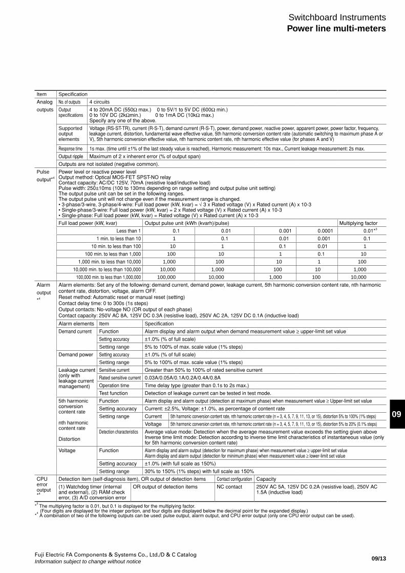
No. of outputs 4 circuits
Output specifications
4 to 20mA DC (550Ω max.) 0 to 5V/1 to 5V DC (600Ω min.) 0 to 10V DC (2kΩmin.) 0 to 1mA DC (10kΩ max.) Specify any one of the above.
Supported output elements
Voltage (RS-ST-TR), current (R-S-T), demand current (R-S-T), power, demand power, reactive power, apparent power, power factor, frequency, leakage current, distortion, fundamental wave effective value, 5th harmonic conversion content rate (automatic switching to maximum phase A or V), 5th harmonic conversion effective value, nth harmonic content rate, nth harmonic effective value (for phases A and V)
Response time 1s max. (time until ±1% of the last steady value is reached), Harmonic measurement: 10s max., Current leakage measurement: 2s max.
Output ripple Maximum of 2 x inherent error (% of output span)
Outputs are not isolated (negative common).
Pulse
output*4
Power level or reactive power level Output method: Optical MOS-FET SPST-NO relay Contact capacity: AC/DC 125V, 70mA (resistive load/inductive load) Pulse width: 250±10ms (100 to 130ms depending on range setting and output pulse unit setting) The output pulse unit can be set in the following ranges. The output pulse unit will not change even if the measurement range is changed. • 3-phase/3-wire, 3-phase/4-wire: Full load power (kW, kvar) = √ 3 x Rated voltage (V) x Rated current (A) x 10-3 • Single-phase/3-wire: Full load power (kW, kvar) = 2 x Rated voltage (V) x Rated current (A) x 10-3 • Single-phase: Full load power (kW, kvar) = Rated voltage (V) x Rated current (A) x 10-3
Full load power (kW, kvar) Output pulse unit (kWh (kvarh)/pulse) Multiplying factor
Less than 1 0.1 0.01 0.001 0.0001 0.01*3
1 min. to less than 10 1 0.1 0.01 0.001 0.1
10 min. to less than 100 10 1 0.1 0.01 1
100 min. to less than 1,000 100 10 1 0.1 10
1,000 min. to less than 10,000 1,000 100 10 1 100
10,000 min. to less than 100,000 10,000 1,000 100 10 1,000
100,000 min. to less than 1,000,000 100,000 10,000 1,000 100 10,000
Alarm
output
*4
Alarm elements: Set any of the following: demand current, demand power, leakage current, 5th harmonic conversion content rate, nth harmonic content rate, distortion, voltage, alarm OFF. Reset method: Automatic reset or manual reset (setting) Contact delay time: 0 to 300s (1s steps) Output contacts: No-voltage NO (OR output of each phase) Contact capacity: 250V AC 8A, 125V DC 0.3A (resistive load), 250V AC 2A, 125V DC 0.1A (inductive load)
Alarm elements Item Specification
Demand current Function Alarm display and alarm output when demand measurement value ≥ upper-limit set value
Setting accuracy ±1.0% (% of full scale)
Setting range 5% to 100% of max. scale value (1% steps)
Demand power Setting accuracy ±1.0% (% of full scale)
Setting range 5% to 100% of max. scale value (1% steps)
Leakage current (only with leakage current management)
Sensitive current Greater than 50% to 100% of rated sensitive current
Rated sensitive current 0.03A/0.05A/0.1A/0.2A/0.4A/0.8A
Operation time Time delay type (greater than 0.1s to 2s max.)
Test function Detection of leakage current can be tested in test mode.
5th harmonic conversion content rate
nth harmonic content rate Distortion
Function Alarm display and alarm output (detection at maximum phase) when measurement value ≥ Upper-limit set value
Setting accuracy Current: ±2.5%, Voltage: ±1.0%, as percentage of content rate
Setting range Current 5th harmonic conversion content rate, nth harmonic content rate (n = 3, 4, 5, 7, 9, 11, 13, or 15), distortion 5% to 100% (1% steps)
Voltage 5th harmonic conversion content rate, nth harmonic content rate (n = 3, 4, 5, 7, 9, 11, 13, or 15), distortion 5% to 20% (0.1% steps)
Detection characteristics Average value mode: Detection when the average measurement value exceeds the setting given above Inverse time limit mode: Detection according to inverse time limit characteristics of instantaneous value (only for 5th harmonic conversion content rate)
Voltage Function Alarm display and alarm output (detection for maximum phase) when measurement value ≥ upper-limit set value Alarm display and alarm output (detection for minimum phase) when measurement value ≥ lower-limit set value
Setting accuracy ±1.0% (with full scale as 150%)
Setting range 30% to 150% (1% steps) with full scale as 150%
CPU error output*4
Detection item (self-diagnosis item), OR output of detection items Contact configuration Capacity
(1) Watchdog timer (internal and external), (2) RAM check error, (3) A/D conversion error
OR output of detection items NC contact 250V AC 5A, 125V DC 0.2A (resistive load), 250V AC 1.5A (inductive load)
*3 The multiplying factor is 0.01, but 0.1 is displayed for the multiplying factor.
(Four digits are displayed for the integer portion, and four digits are displayed below the decimal point for the expanded display.) *
4 A combination of two of the following outputs can be used: pulse output, alarm output, and CPU error output (only one CPU error output can be used).
Fuji Electric FA Components & Systems Co., Ltd./D & C CatalogInformation subject to change without notice09/14
Switchboard InstrumentsPower line multi-meters
Item Specification
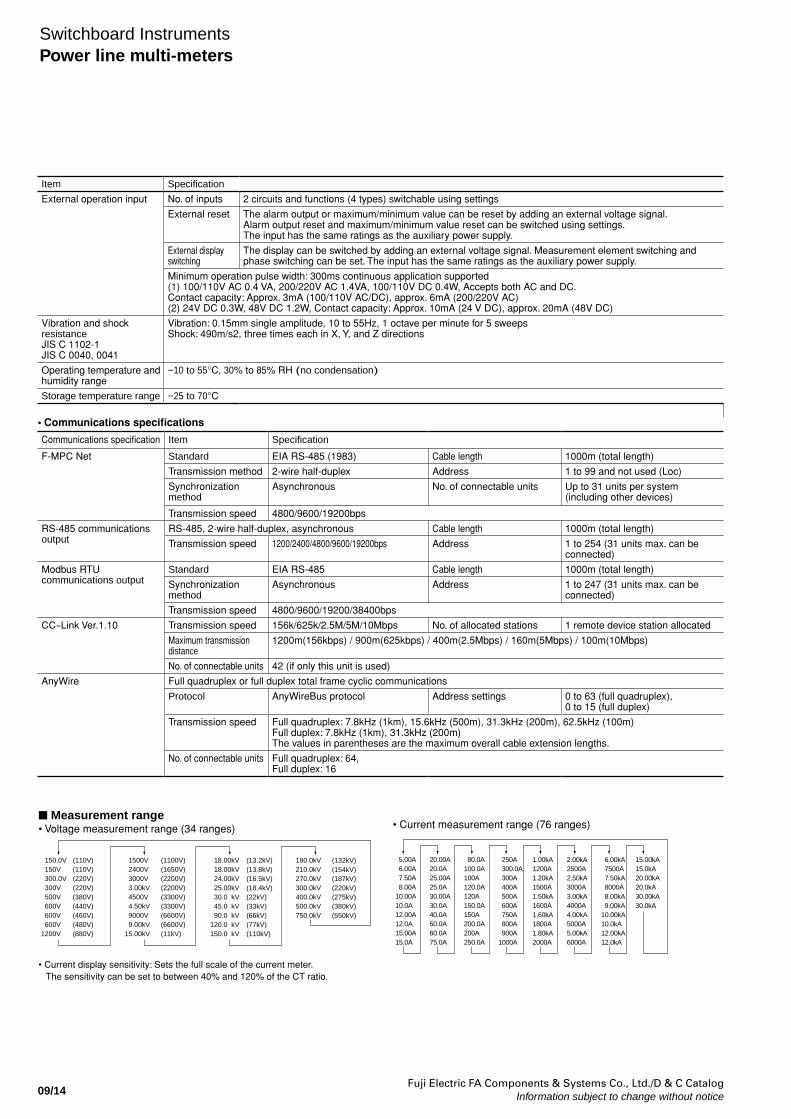
External operation input No. of inputs 2 circuits and functions (4 types) switchable using settings
External reset The alarm output or maximum/minimum value can be reset by adding an external voltage signal. Alarm output reset and maximum/minimum value reset can be switched using settings. The input has the same ratings as the auxiliary power supply.
External display switching
The display can be switched by adding an external voltage signal. Measurement element switching and phase switching can be set. The input has the same ratings as the auxiliary power supply.
Minimum operation pulse width: 300ms continuous application supported (1) 100/110V AC 0.4 VA, 200/220V AC 1.4VA, 100/110V DC 0.4W, Accepts both AC and DC. Contact capacity: Approx. 3mA (100/110V AC/DC), approx. 6mA (200/220V AC) (2) 24V DC 0.3W, 48V DC 1.2W, Contact capacity: Approx. 10mA (24 V DC), approx. 20mA (48V DC)
Vibration and shock resistanceJIS C 1102-1JIS C 0040, 0041
Vibration: 0.15mm single amplitude, 10 to 55Hz, 1 octave per minute for 5 sweeps Shock: 490m/s2, three times each in X, Y, and Z directions
Operating temperature and humidity range
−10 to 55°C, 30% to 85% RH (no condensation)
Storage temperature range −25 to 70°C
Communications specification Item Specification
F-MPC Net Standard EIA RS-485 (1983) Cable length 1000m (total length)
Transmission method 2-wire half-duplex Address 1 to 99 and not used (Loc)
Synchronization method
Asynchronous No. of connectable units Up to 31 units per system (including other devices)
Transmission speed 4800/9600/19200bps
RS-485 communications output
RS-485, 2-wire half-duplex, asynchronous Cable length 1000m (total length)
Transmission speed 1200/2400/4800/9600/19200bps Address 1 to 254 (31 units max. can be connected)
Modbus RTU communications output
Standard EIA RS-485 Cable length 1000m (total length)
Synchronization method
Asynchronous Address 1 to 247 (31 units max. can be connected)
Transmission speed 4800/9600/19200/38400bps
CC-Link Ver.1.10 Transmission speed 156k/625k/2.5M/5M/10Mbps No. of allocated stations 1 remote device station allocated
Maximum transmission distance
1200m(156kbps) / 900m(625kbps) / 400m(2.5Mbps) / 160m(5Mbps) / 100m(10Mbps)
No. of connectable units 42 (if only this unit is used)
AnyWire Full quadruplex or full duplex total frame cyclic communications
Protocol AnyWireBus protocol Address settings 0 to 63 (full quadruplex), 0 to 15 (full duplex)
Transmission speed Full quadruplex: 7.8kHz (1km), 15.6kHz (500m), 31.3kHz (200m), 62.5kHz (100m)Full duplex: 7.8kHz (1km), 31.3kHz (200m)The values in parentheses are the maximum overall cable extension lengths.
No. of connectable units Full quadruplex: 64, Full duplex: 16
• Communications specifications
Measurement range• Voltage measurement range (34 ranges)
150.0V 150V 300.0V 300V 500V 600V 600V 600V1200V
1500V 2400V 3000V 3.00kV 4500V 4.50kV 9000V 9.00kV15.00kV
(110V)(110V)(220V)(220V)(380V)(440V)(460V)(480V)(880V)
(1100V)(1650V)(2200V)(2200V)(3300V)(3300V)(6600V)(6600V)(11kV)
18.00kV 18.00kV 24.00kV 25.00kV 30.0 kV 45.0 kV 90.0 kV120.0 kV150.0 kV
(13.2kV)(13.8kV)(16.5kV)(18.4kV)(22kV)(33kV)(66kV)(77kV)(110kV)
180.0kV210.0kV270.0kV300.0kV400.0kV500.0kV750.0kV
(132kV)(154kV)(187kV)(220kV)(275kV)(380kV)(550kV)
• Current measurement range (76 ranges)
5.00A 6.00A 7.50A 8.00A10.00A10.0A12.00A12.0A15.00A15.0A
20.00A20.0A25.00A25.0A30.00A30.0A40.0A50.0A60.0A75.0A
80.0A100.0A100A120.0A120A150.0A150A200.0A200A250.0A
250A 300.0A 300A 400A 500A 600A 750A 800A 900A1000A
1.00kA1200A1.20kA1500A1.50kA1600A1.60kA1800A1.80kA2000A
2.00kA2500A2.50kA3000A3.00kA4000A4.00kA5000A5.00kA6000A
6.00kA 7500A 7.50kA 8000A 8.00kA 9.00kA10.00kA10.0kA12.00kA12.0kA
15.00kA15.0kA20.00kA20.0kA30.00kA30.0kA
• Current display sensitivity: Sets the full scale of the current meter. The sensitivity can be set to between 40% and 120% of the CT ratio.
Fuji Electric FA Components & Systems Co., Ltd./D & C CatalogInformation subject to change without notice 09/15
09
Switchboard InstrumentsPower line multi-meters
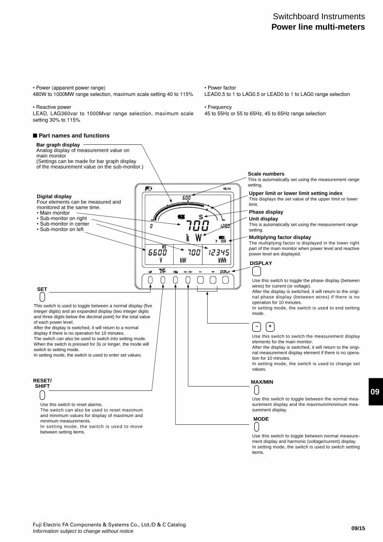
• Power (apparent power range)480W to 1000MW range selection, maximum scale setting 40 to 115%
• Reactive powerLEAD, LAG360var to 1000Mvar range selection, maximum scale setting 30% to 115%
• Power factorLEAD0.5 to 1 to LAG0.5 or LEAD0 to 1 to LAG0 range selection
• Frequency45 to 55Hz or 55 to 65Hz, 45 to 65Hz range selection
Part names and functions
S
SET
This switch is used to toggle between a normal display (five integer digits) and an expanded display (two integer digits and three digits below the decimal point) for the total value of each power level. After the display is switched, it will return to a normal display if there is no operation for 10 minutes. The switch can also be used to switch into setting mode. When the switch is pressed for 3s or longer, the mode will switch to setting mode. In setting mode, the switch is used to enter set values.
Use this switch to reset alarms. The switch can also be used to reset maximum and minimum values for display of maximum and minimum measurements. In sett ing mode, the switch is used to move between setting items.
RESET/SHIFT
DISPLAY
MAX/MIN
MODE
Scale numbersThis is automatically set using the measurement range setting.
Upper limit or lower limit setting index This displays the set value of the upper limit or lower limit.
Unit displayThis is automatically set using the measurement range setting.
Phase display
Multiplying factor displayThe multiplying factor is displayed in the lower right part of the main monitor when power level and reactive power level are displayed.
Use this switch to toggle the phase display (between wires) for current (or voltage). After the display is switched, it will return to the origi-nal phase display (between wires) if there is no operation for 10 minutes. In setting mode, the switch is used to end setting mode.
Use this switch to switch the measurement display elements for the main monitor. After the display is switched, it will return to the origi-nal measurement display element if there is no opera-tion for 10 minutes.In setting mode, the switch is used to change set values.
Use this switch to toggle between the normal mea-surement display and the maximum/minimum mea-surement display.
Use this switch to toggle between normal measure-ment display and harmonic (voltage/current) display.In setting mode, the switch is used to switch setting items.
– +
Bar graph displayAnalog display of measurement value on main monitor(Settings can be made for bar graph display of the measurement value on the sub-monitor.)
Digital displayFour elements can be measured and monitored at the same time. • Main monitor• Sub-monitor on right• Sub-monitor in center• Sub-monitor on left
Fuji Electric FA Components & Systems Co., Ltd./D & C CatalogInformation subject to change without notice09/16
Switchboard InstrumentsPower line multi-meters
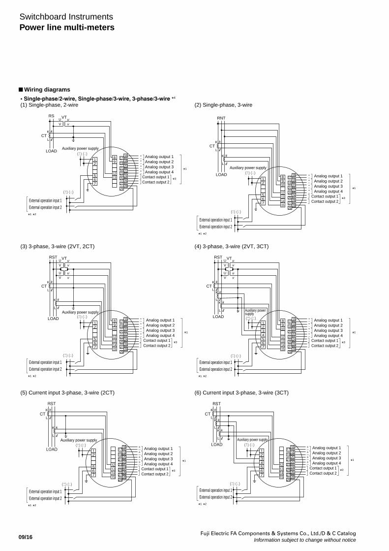
Wiring diagrams
• Single-phase/2-wire, Single-phase/3-wire, 3-phase/3-wire *4
(1) Single-phase, 2-wire (2) Single-phase, 3-wire
(3) 3-phase, 3-wire (2VT, 2CT) (4) 3-phase, 3-wire (2VT, 3CT)
(5) Current input 3-phase, 3-wire (2CT) (6) Current input 3-phase, 3-wire (3CT)
12
567
89
1213
1716182022242628
192123252729
12
567
8910
12131415
1716182022242628
192123252729
RS
LOAD
*1 *2
External operation input 1 External operation input 2
Auxiliary power supply
Auxiliary power supply
Auxiliary power supply
Auxiliary power supply
Auxiliary power supply
Auxiliary power supply
CT
VTUV
K
L
u
k
v
Analog output 1Analog output 2Analog output 3Analog output 4
Contact output 1Contact output 2
*1
*3
*1 *2
External operation input 1 External operation input 2
*1 *2
External operation input 1 External operation input 2
*1 *2
External operation input 1 External operation input 2
*1 *2
External operation input 1 External operation input 2
*1 *2
External operation input 1 External operation input 2
Analog output 1Analog output 2Analog output 3Analog output 4
Contact output 1Contact output 2
*1
*3
Analog output 1Analog output 2Analog output 3Analog output 4
Contact output 1Contact output 2
*1
*3
Analog output 1Analog output 2Analog output 3Analog output 4
Contact output 1Contact output 2
*1
*3
Analog output 1Analog output 2Analog output 3Analog output 4
Contact output 1Contact output 2
*1
*3
Analog output 1Analog output 2Analog output 3Analog output 4
Contact output 1Contact output 2
*1
*3
RNT
LOAD +–+–+–+–
+–+–+–+–
+–+–+–+–
+–+–+–+–
CTK
L
k
K
L
k
12
567
8910
12131415
1716182022242628
192123252729
1234567
8910
12131415
1716182022242628
192123252729
VTUV
uv
UV
uv
RST
LOAD
CTK
L
k
K
L
k
VTUV
uv
UV
uv
RST
LOAD
CTK
L
k
K
L
k
K
L
k
12
567
12131415
17 16182022242628
192123252729
1234567
12131415
17 16182022242628
192123252729
RST
LOAD +-+-+-+-
CTK
L
k
K
L
k
RST
LOAD+-+-+-+-
CTK
L
k
K
L
k
K
L
k
Fuji Electric FA Components & Systems Co., Ltd./D & C CatalogInformation subject to change without notice 09/17
09
Switchboard InstrumentsPower line multi-meters
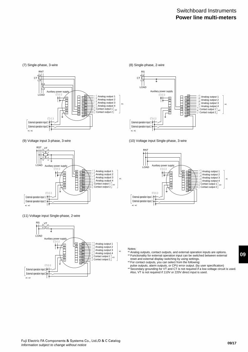
(7) Single-phase, 3-wire (8) Single-phase, 2-wire
(9) Voltage input 3-phase, 3-wire
(11) Voltage input Single-phase, 2-wire
(10) Voltage input Single-phase, 3-wire
Auxiliary power supplyAuxiliary power supply
*1 *2
External operation input 1 External operation input 2
*1 *2
External operation input 1 External operation input 2
*1 *2
External operation input 1 External operation input 2
*1 *2
External operation input 1 External operation input 2
*1 *2
External operation input 1 External operation input 2
Analog output 1Analog output 2Analog output 3Analog output 4
Contact output 1Contact output 2
*1
*1
*3
Analog output 1Analog output 2Analog output 3Analog output 4
Contact output 1Contact output 2 *3
*1
Analog output 1Analog output 2Analog output 3Analog output 4
Notes:*1 Analog outputs, contact outputs, and external operation inputs are options. *2 Functionality for external operation input can be switched between external reset and external display switching by using settings. *3 For contact outputs, you can select from the following: pulse outputs, alarm outputs, or CPU error output. (by user specification)*4 Secondary grounding for VT and CT is not required if a low-voltage circuit is used. Also, VT is not required if 110V or 220V direct input is used.
Contact output 1Contact output 2 *3
Analog output 1Analog output 2Analog output 3Analog output 4
Contact output 1Contact output 2
*1
*3
Analog output 1Analog output 2Analog output 3Analog output 4
Contact output 1Contact output 2
*1
*3
Auxiliary power supply
Auxiliary power supply
Auxiliary power supply
12
567
12131415
1716182022242628
192123252729
12
567
1213
1716182022242628
192123252729
RNT
LOAD +–+–+–+–
+–+–+–+–
+–+–+–+–
+–+–+–+–
+–+–+–+–
CTK
L
k
K
L
k
RS
LOAD
CTK
L
k
12
567
8910
1716182022242628
192123252729
12
567
8910
1716182022242628
192123252729
VTUV
uv
UV
uv
RST
LOAD
RNT
LOAD
12
567
89
1716182022242628
192123252729
VTUV
uv
RS
LOAD
Fuji Electric FA Components & Systems Co., Ltd./D & C CatalogInformation subject to change without notice09/18
Switchboard InstrumentsPower line multi-meters
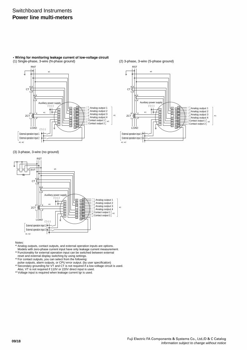
• Wiring for monitoring leakage current of low-voltage circuit(1) Single-phase, 3-wire (N-phase ground) (2) 3-phase, 3-wire (S-phase ground)
(3) 3-phase, 3-wire (no ground)
*1 *2
External operation input 1 External operation input 2
*1 *2
External operation input 1 External operation input 2
*1 *2
External operation input 1 External operation input 2
*1
Analog output 1Analog output 2Analog output 3Analog output 4
Contact output 1Contact output 2 *3
*5
*5
*1
*1
*1
*5
*1
Analog output 1Analog output 2Analog output 3Analog output 4
Contact output 1Contact output 2 *3
Notes:*1 Analog outputs, contact outputs, and external operation inputs are options. Models with zero-phase current input have only leakage current measurement. *2 Functionality for external operation input can be switched between external reset and external display switching by using settings. *3 For contact outputs, you can select from the following: pulse outputs, alarm outputs, or CPU error output. (by user specification)*4 Secondary grounding for VT and CT is not required if a low-voltage circuit is used. Also, VT is not required if 110V or 220V direct input is used. *5 Voltage input is required when leakage current Igr is used.
Analog output 1Analog output 2Analog output 3Analog output 4
Contact output 1Contact output 2
*1
*3
Auxiliary power supply
Auxiliary power supply
Auxiliary power supply
+–+–+–+–
+–+–+–+–
+–+–+–+–
1234567
8910
12131415
1716182022242628
192123252729
1234567
8910
12131415
1716182022242628
192123252729
RNT
LOAD
CTK
L
k
ZCTK
L
k
K
L
k
RST
LOAD
CTK
L
k
ZCTK
L
k
K
L
k
1234567
8910
12131415
1716182022242628
192123252729
RST
LOAD
CT
EVT
K
L
k
ZCTK
L
k
K
L
k
Fuji Electric FA Components & Systems Co., Ltd./D & C CatalogInformation subject to change without notice 09/19
09
Switchboard InstrumentsPower line multi-meters
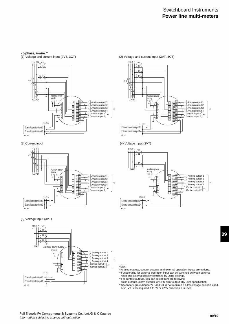
• 3-phase, 4-wire *4
(1) Voltage and current input (2VT, 3CT) (2) Voltage and current input (3VT, 3CT)
(3) Current input
(5) Voltage input (3VT)
(4) Voltage input (2VT)
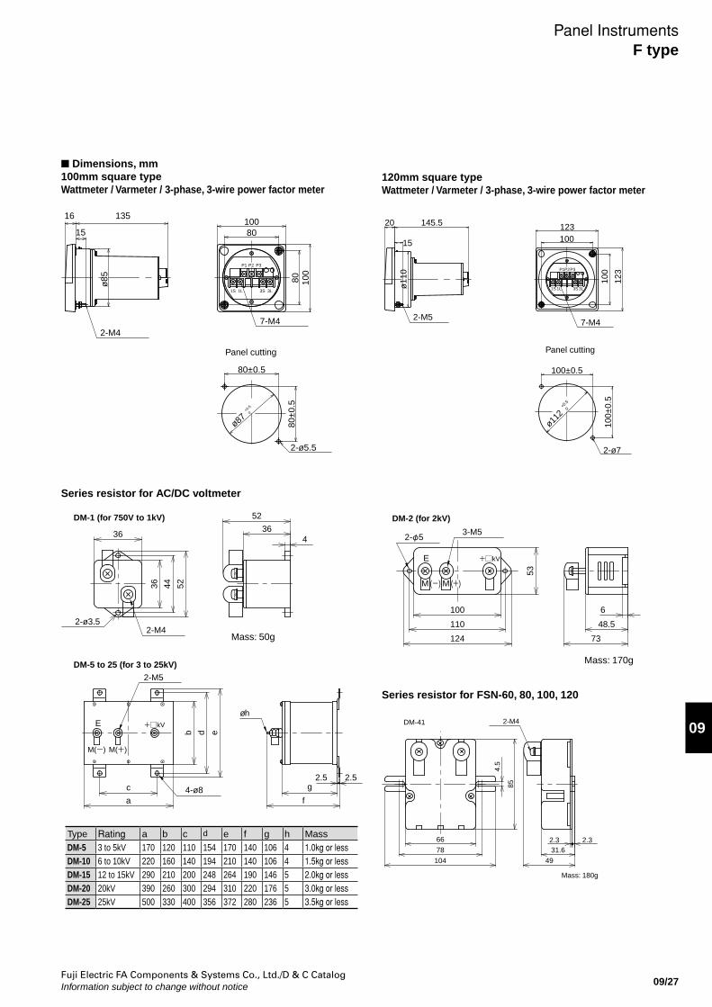
*1 *2
External operation input 1 External operation input 2
*1 *2
External operation input 1 External operation input 2
*1 *2
External operation input 1 External operation input 2
*1 *2
External operation input 1 External operation input 2
*1 *2
External operation input 1 External operation input 2
*1
Analog output 1Analog output 2Analog output 3Analog output 4
Contact output 1Contact output 2 *3
*1
Analog output 1Analog output 2Analog output 3Analog output 4
Contact output 1Contact output 2 *3
*1
Analog output 1Analog output 2Analog output 3Analog output 4
Contact output 1Contact output 2 *3
*1
Analog output 1Analog output 2Analog output 3Analog output 4
Contact output 1Contact output 2 *3
*1
Analog output 1Analog output 2Analog output 3Analog output 4
Contact output 1Contact output 2 *3
Notes:*1 Analog outputs, contact outputs, and external operation inputs are options.*2 Functionality for external operation input can be switched between external reset and external display switching by using settings. *3 For contact outputs, you can select from the following: pulse outputs, alarm outputs, or CPU error output. (by user specification)*4 Secondary grounding for VT and CT is not required if a low-voltage circuit is used. Also, VT is not required if 110V or 220V direct input is used.
Auxiliary power supply
Auxiliary power supply
Auxiliary power supply
Auxiliary power supply
Auxiliary power supply
+–+–+–+–
+–+–+–+–
+–+–+–+–
+–+–+–+–
+–+–+–+–
1234567
8
101112131415
1716182022242628
192123252729
1234567
89101112131415
1716182022242628
192123252729
VTUV
uv
UV
uv
R S T N
LOAD
CTK
L
k
K
L
k
K
L
k
VTUV
uv
UV
uv
UV
uv
R S T N
LOAD
CTK
L
k
K
L
k
K
L
k
1234567
12131415
1716182022242628
192123252729
12
567
8
1011
1716182022242628
192123252729
R S T N
LOAD
CTK
L
k
K
L
k
K
L
k
VTUV
uv
UV
uv
R S T N
LOAD
12
567
891011
1716182022242628
192123252729
VTUV
uv
UV
uv
UV
uv
R S T N
LOAD
Fuji Electric FA Components & Systems Co., Ltd./D & C CatalogInformation subject to change without notice09/20
Switchboard InstrumentsPower line multi-meters
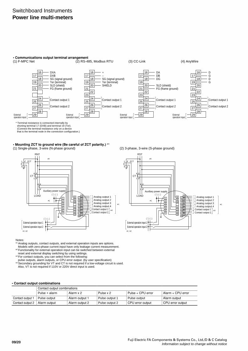
• Communications output terminal arrangement (1) F-MPC Net
• Mounting ZCT to ground wire (Be careful of ZCT polarity.) *4 (1) Single-phase, 3-wire (N-phase ground) (2) 3-phase, 3-wire (S-phase ground)
(2) RS-485, Modbus RTU (3) CC-Link
*1 *2
External operation input 1 External operation input 2
*1 *2
External operation input 1 External operation input 2
*1
Analog output 1Analog output 2Analog output 3Analog output 4
Contact output 1Contact output 2 *3
*1
Analog output 1Analog output 2Analog output 3Analog output 4
Contact output 1Contact output 2 *3
Auxiliary power supply Auxiliary power supply
+–+–+–+–
+–+–+–+–
* Terminal resistance is connected internally by shorting terminal 17 (DXB) and terminal 19 (Ter). (Connect the terminal resistance only on a device that is the terminal node in the connection configuration.)
+–SG (signal ground) Ter (terminal) SHIELD
Contact output 1
Contact output 2
1716
18
20
22
24
26
28
19
21
23
25
27
29External operation input
External operation input
External operation input
DXADXBSG (signal ground) Ter (terminal) SLD (shield) FG (frame ground)
Contact output 1
Contact output 2
1716
18
20
24
26
28
19
21
25
27
29
DADBDG
SLD (shield) FG (frame ground)
Contact output 1
Contact output 2
1716
18
20
22
24
26
28
19
21
23
25
27
29
(4) AnyWire
External operation input
DGDG
Contact output 1
Contact output 2
1716
18
20
22
24
26
28
19
21
23
25
27
29
1234567
8910
12131415
1716182022242628
192123252729
1234567
8910
12131415
1716182022242628
192123252729
L ZCT
K
RNT
LOAD
CTK
L
k
k
K
L
k
L ZCT
K
RST
LOAD
CTK
L
k
k
K
L
k
*5
*1
*5
*1
Notes:*1 Analog outputs, contact outputs, and external operation inputs are options. Models with zero-phase current input have only leakage current measurement. *2 Functionality for external operation input can be switched between external reset and external display switching by using settings. *3 For contact outputs, you can select from the following: pulse outputs, alarm outputs, or CPU error output. (by user specification)*4 Secondary grounding for VT and CT is not required if a low-voltage circuit is used. Also, VT is not required if 110V or 220V direct input is used. *5 Voltage input is required when leakage current Igr is used.
Contact output combinations
Pulse + alarm Alarm x 2 Pulse x 2 Pulse + CPU error Alarm + CPU error
Contact output 1 Pulse output Alarm output 1 Pulse output 1 Pulse output Alarm output
Contact output 2 Alarm output Alarm output 2 Pulse output 2 CPU error output CPU error output
• Contact output combinations
Fuji Electric FA Components & Systems Co., Ltd./D & C CatalogInformation subject to change without notice 09/21
09
Switchboard InstrumentsPower line multi-meters
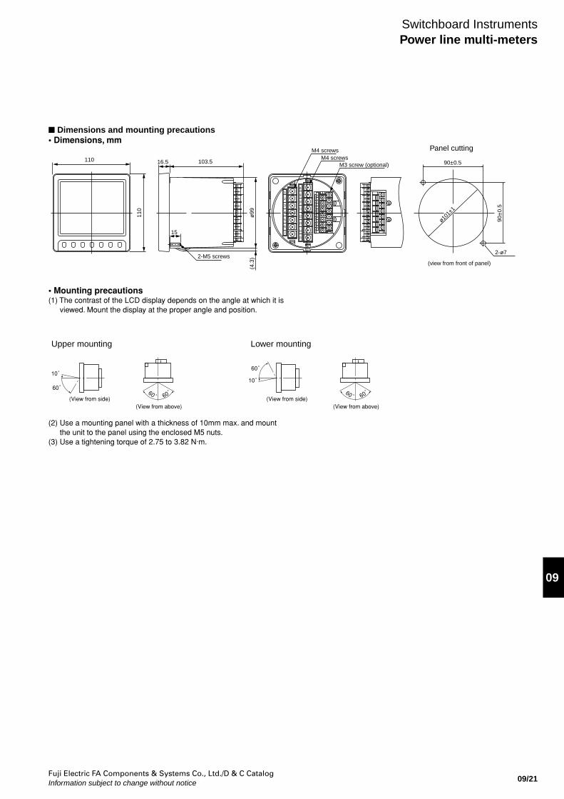
Dimensions and mounting precautions• Dimensions, mm
• Mounting precautions(1) The contrast of the LCD display depends on the angle at which it is
viewed. Mount the display at the proper angle and position.
1
2
3
4
5
6
7
8
9
10
16
18
20
22
24
26
28
11
12
13
14
15
17
19
21
23
25
27
29
110
110
16.5 103.5
15
2-M5 screwsø
99(4
.3)
M4 screwsM4 screws
M3 screw (optional) 90±0.5
90±
0.5
2-ø7
ø101±
1
Panel cutting
(view from front of panel)
10゜
60゜
(View from side) 60゜
60゜
(View from above)
10゜
60゜
(View from side) 60゜
60゜
(View from above)
Upper mounting Lower mounting
(2) Use a mounting panel with a thickness of 10mm max. and mount the unit to the panel using the enclosed M5 nuts.
(3) Use a tightening torque of 2.75 to 3.82 N·m.
Fuji Electric FA Components & Systems Co., Ltd./D & C CatalogInformation subject to change without notice09/22
Switchboard InstrumentsPower line multi-meters
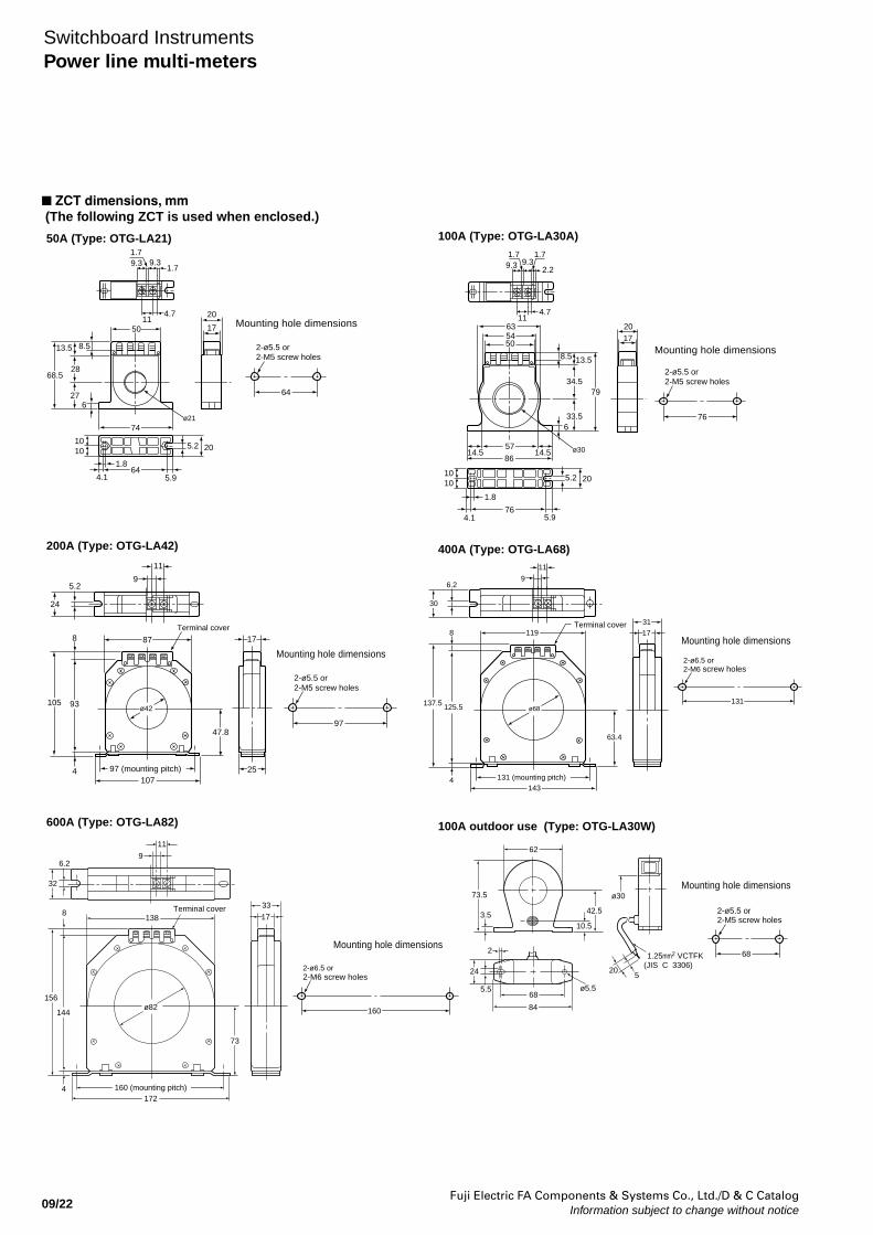
ZCT dimensions, mm (The following ZCT is used when enclosed.)
9.31.7
1.79.3
114.7
17
20
50
8.513.5
28
27
68.5
6
74
205.2
645.94.1
1.8
1010
64
2-ø5.5 or2-M5 screw holes
Mounting hole dimensions
ø21
50A (Type: OTG-LA21) 100A (Type: OTG-LA30A)
400A (Type: OTG-LA68)
100A outdoor use (Type: OTG-LA30W)
200A (Type: OTG-LA42)
600A (Type: OTG-LA82)
1.7 1.79.3 9.3
2.2
114.7
2017
635450
8.5 13.5
33.5
34.579
6
57
8614.514.5
205.2
5.976
1.8
4.1
76
2-ø5.5 or2-M5 screw holes
1010
Mounting hole dimensions
ø30
17
25
24
5.29
11
Terminal cover
878
105 93
4
ø42
97 (mounting pitch) 107
47.897
2-ø5.5 or2-M5 screw holes
Mounting hole dimensions
17
31
143131 (mounting pitch)
ø68
63.4
Terminal cover8
4
125.5137.5
119
11
96.2
30
131
2-ø6.5 or2-M6 screw holes
Mounting hole dimensions
11
96.2
32
Terminal cover138
8
156
144
73
172160 (mounting pitch) 4
33
17
ø82 160
2-ø6.5 or2-M6 screw holes
Mounting hole dimensions
ø30
205
1.25mm2 VCTFK(JIS C 3306)
42.5
10.5
62
3.5
73.5
ø5.5
2
5.5
24
68
84
68
2-ø5.5 or2-M5 screw holes
Mounting hole dimensions
Fuji Electric FA Components & Systems Co., Ltd./D & C CatalogInformation subject to change without notice 09/23
09
Meter Description 60mm squareType
80mm squareType
100mm squareType
120mm squareType
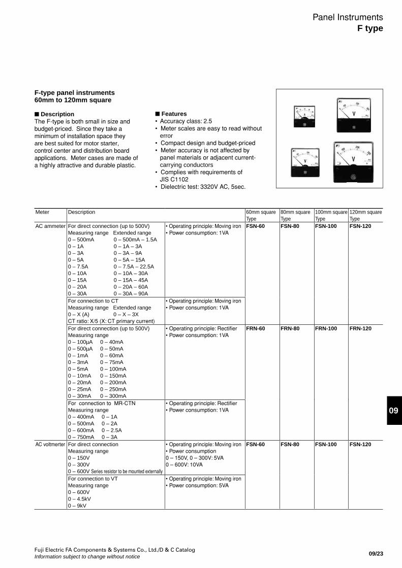
AC ammeter For direct connection (up to 500V)Measuring range Extended range0 – 500mA 0 – 500mA – 1.5A0 – 1A 0 – 1A – 3A0 – 3A 0 – 3A – 9A0 – 5A 0 – 5A – 15A0 – 7.5A 0 – 7.5A – 22.5A0 – 10A 0 – 10A – 30A0 – 15A 0 – 15A – 45A0 – 20A 0 – 20A – 60A0 – 30A 0 – 30A – 90A
• Operating principle: Moving iron• Power consumption: 1VA
FSN-60 FSN-80 FSN-100 FSN-120
For connection to CTMeasuring range Extended range0 – X (A) 0 – X – 3XCT ratio: X/5 (X: CT primary current)
• Operating principle: Moving iron• Power consumption: 1VA
For direct connection (up to 500V)Measuring range 0 – 100µA 0 – 40mA0 – 500µA 0 – 50mA0 – 1mA 0 – 60mA0 – 3mA 0 – 75mA0 – 5mA 0 – 100mA0 – 10mA 0 – 150mA0 – 20mA 0 – 200mA0 – 25mA 0 – 250mA0 – 30mA 0 – 300mA
• Operating principle: Rectifier• Power consumption: 1VA
FRN-60 FRN-80 FRN-100 FRN-120
For connection to MR-CTNMeasuring range 0 – 400mA 0 – 1A0 – 500mA 0 – 2A0 – 600mA 0 – 2.5A0 – 750mA 0 – 3A
• Operating principle: Rectifier• Power consumption: 1VA
AC voltmerter For direct connectionMeasuring range 0 – 150V0 – 300V0 – 600V Series resistor to be mounted externally
• Operating principle: Moving iron• Power consumption0 – 150V, 0 – 300V: 5VA0 – 600V: 10VA
FSN-60 FSN-80 FSN-100 FSN-120
For connection to VTMeasuring range 0 – 600V0 – 4.5kV0 – 9kV
• Operating principle: Moving iron• Power consumption: 5VA
Panel InstrumentsF type
F-type panel instruments60mm to 120mm square
DescriptionThe F-type is both small in size and budget-priced. Since they take a minimum of installation space they are best suited for motor starter, control center and distribution board applications. Meter cases are made of a highly attractive and durable plastic.
Features• Accuracy class: 2.5 • Meter scales are easy to read without
error• Compact design and budget-priced• Meter accuracy is not affected by
panel materials or adjacent current-carrying conductors
• Complies with requirements of JIS C1102
• Dielectric test: 3320V AC, 5sec.
Fuji Electric FA Components & Systems Co., Ltd./D & C CatalogInformation subject to change without notice09/24
Meter Description 60mm squareType
80mm squareType
100mm squareType
120mm squareType
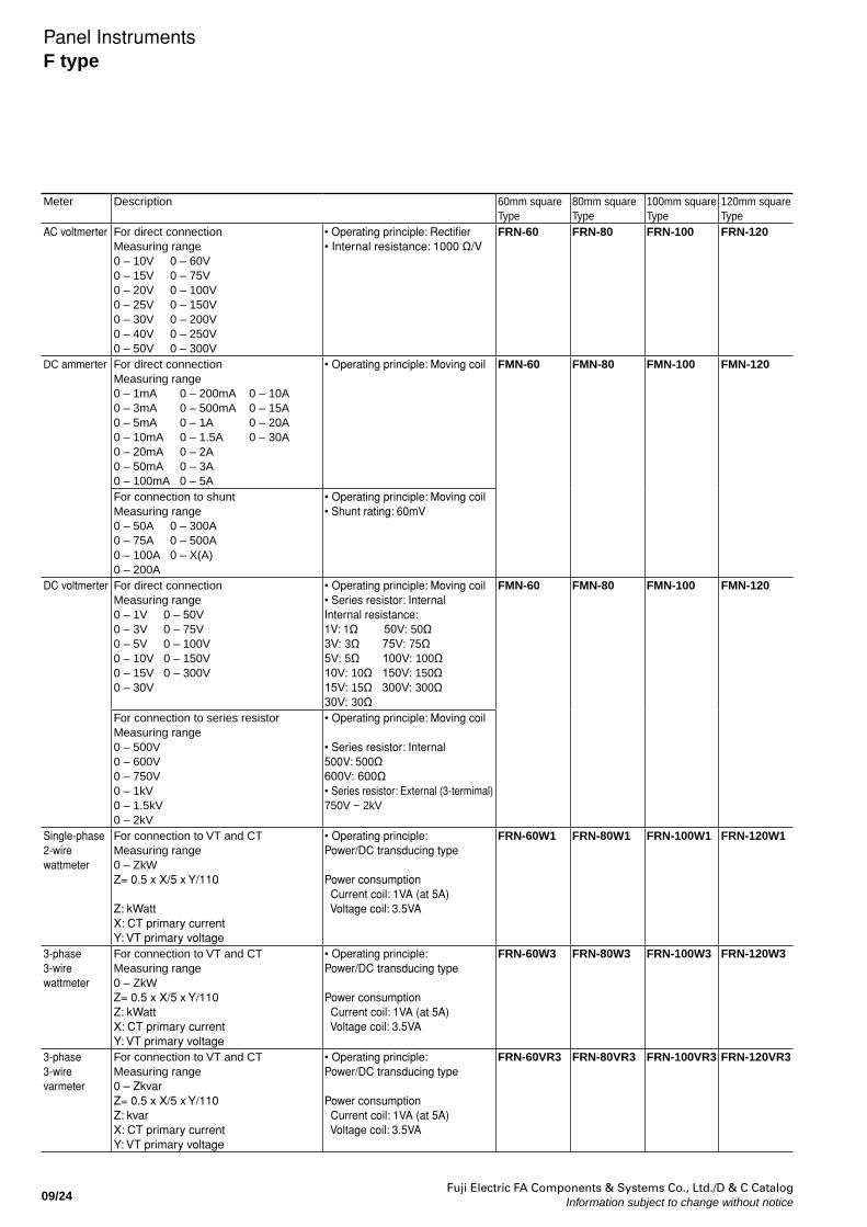
AC voltmerter For direct connectionMeasuring range 0 – 10V 0 – 60V 0 – 15V 0 – 75V0 – 20V 0 – 100V0 – 25V 0 – 150V0 – 30V 0 – 200V0 – 40V 0 – 250V0 – 50V 0 – 300V
• Operating principle: Rectifier• Internal resistance: 1000 Ω/V
FRN-60 FRN-80 FRN-100 FRN-120
DC ammerter For direct connectionMeasuring range 0 – 1mA 0 – 200mA 0 – 10A0 – 3mA 0 – 500mA 0 – 15A0 – 5mA 0 – 1A 0 – 20A0 – 10mA 0 – 1.5A 0 – 30A0 – 20mA 0 – 2A0 – 50mA 0 – 3A0 – 100mA 0 – 5A
• Operating principle: Moving coil FMN-60 FMN-80 FMN-100 FMN-120
For connection to shuntMeasuring range 0 – 50A 0 – 300A0 – 75A 0 – 500A0 – 100A 0 – X(A)0 – 200A
• Operating principle: Moving coil• Shunt rating: 60mV
DC voltmerter For direct connectionMeasuring range0 – 1V 0 – 50V 0 – 3V 0 – 75V0 – 5V 0 – 100V0 – 10V 0 – 150V0 – 15V 0 – 300V0 – 30V
• Operating principle: Moving coil• Series resistor: InternalInternal resistance:1V: 1Ω 50V: 50Ω3V: 3Ω 75V: 75Ω5V: 5Ω 100V: 100Ω10V: 10Ω 150V: 150Ω15V: 15Ω 300V: 300Ω30V: 30Ω
FMN-60 FMN-80 FMN-100 FMN-120
For connection to series resistorMeasuring range0 – 500V0 – 600V0 – 750V0 – 1kV0 – 1.5kV0 – 2kV
• Operating principle: Moving coil
• Series resistor: Internal500V: 500Ω600V: 600Ω• Series resistor: External (3-termimal)750V ~ 2kV
Single-phase2-wirewattmeter
For connection to VT and CTMeasuring range0 – ZkWZ= 0.5 x X/5 x Y/110
Z: kWattX: CT primary currentY: VT primary voltage
• Operating principle: Power/DC transducing type
Power consumption Current coil: 1VA (at 5A) Voltage coil: 3.5VA
FRN-60W1 FRN-80W1 FRN-100W1 FRN-120W1
3-phase3-wirewattmeter
For connection to VT and CTMeasuring range0 – ZkWZ= 0.5 x X/5 x Y/110Z: kWattX: CT primary currentY: VT primary voltage
• Operating principle: Power/DC transducing type
Power consumption Current coil: 1VA (at 5A) Voltage coil: 3.5VA
FRN-60W3 FRN-80W3 FRN-100W3 FRN-120W3
3-phase3-wirevarmeter
For connection to VT and CTMeasuring range0 – ZkvarZ= 0.5 x X/5 x Y/110Z: kvarX: CT primary currentY: VT primary voltage
• Operating principle: Power/DC transducing type
Power consumption Current coil: 1VA (at 5A) Voltage coil: 3.5VA
FRN-60VR3 FRN-80VR3 FRN-100VR3 FRN-120VR3
Panel InstrumentsF type
Fuji Electric FA Components & Systems Co., Ltd./D & C CatalogInformation subject to change without notice 09/25
09
Panel InstrumentsF type
Meter Description 60mm squareType
80mm squareType
100mm squareType
120mm squareType
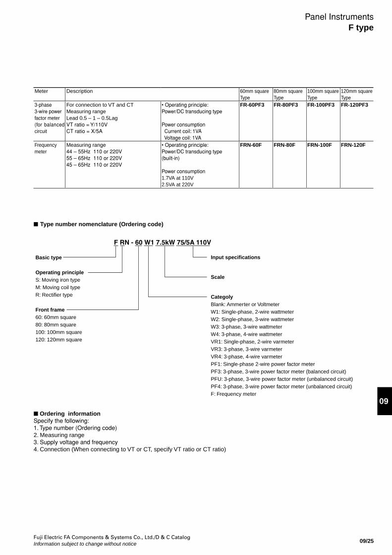
3-phase3-wire powerfactor meter(for balanced circuit
For connection to VT and CTMeasuring rangeLead 0.5 – 1 – 0.5LagVT ratio = Y/110VCT ratio = X/5A
• Operating principle: Power/DC transducing type
Power consumption Current coil: 1VA Voltage coil: 1VA
FR-60PF3 FR-80PF3 FR-100PF3 FR-120PF3
Frequencymeter
Measuring range44 – 55Hz 110 or 220V55 – 65Hz 110 or 220V45 – 65Hz 110 or 220V
• Operating principle: Power/DC transducing type(built-in)
Power consumption1.7VA at 110V2.5VA at 220V
FRN-60F FRN-80F FRN-100F FRN-120F
Type number nomenclature (Ordering code)
F RN - 60 W1 7.5kW 75/5A 110V
Basic type
Operating principleS: Moving iron typeM: Moving coil typeR: Rectifier type
Front frame60: 60mm square80: 80mm square100: 100mm square120: 120mm square
CategolyBlank: Ammerter or VoltmeterW1: Single-phase, 2-wire wattmeterW2: Single-phase, 3-wire wattmeterW3: 3-phase, 3-wire wattmeterW4: 3-phase, 4-wire wattmeterVR1: Single-phase, 2-wire varmeterVR3: 3-phase, 3-wire varmeterVR4: 3-phase, 4-wire varmeter PF1: Single-phase 2-wire power factor meterPF3: 3-phase, 3-wire power factor meter (balanced circuit)PFU: 3-phase, 3-wire power factor meter (unbalanced circuit) PF4: 3-phase, 3-wire power factor meter (unbalanced circuit) F: Frequency meter
Scale
Input specifications
Ordering informationSpecify the following:1. Type number (Ordering code)2. Measuring range 3. Supply voltage and frequency4. Connection (When connecting to VT or CT, specify VT ratio or CT ratio)
Fuji Electric FA Components & Systems Co., Ltd./D & C CatalogInformation subject to change without notice09/26
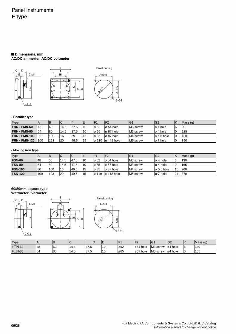
Dimensions, mmAC/DC ammerter, AC/DC voltmeter
Panel InstrumentsF type
Type A B C D E F1 F2 G1 G2 K Mass (g)FRN • FMN-60 48 60 14.5 37.5 10 ø 52 ø 54 hole M3 screw ø 4 hole 6 90FRN • FMN-80 64 80 14.5 37.5 10 ø 65 ø 67 hole M3 screw ø 4 hole 0 125FRN • FMN-100 80 100 16 39 15 ø 85 ø 87 hole M4 screw ø 5.5 hole 0 180FRN • FMN-120 100 123 20 49.5 15 ø 110 ø 112 hole M5 screw ø 7 hole 0 350
Type A B C D E F1 F2 G1 G2 K Mass (g)FSN-60 48 60 14.5 47.5 10 ø 52 ø 54 hole M3 screw ø 4 hole 6 130FSN-80 64 80 14.5 47.5 10 ø 65 ø 67 hole M3 screw ø 4 hole 0 165FSN-100 80 100 16 49.5 15 ø 85 ø 87 hole M4 screw ø 5.5 hole 15 260FSN-120 100 123 20 49.5 15 ø 110 ø 112 hole M5 screw ø 7 hole 24 370
• Rectifier type
• Moving iron type
Panel cuttingC
ED
F1
BA
35
+ − BAA±0.5
A±
0.5
2-G12-G2
2-M4
F2+0
.5
0
K
60/80mm square typeWattmeter / Varmeter
Panel cuttingC
ED
F1
BA
35
BA
A±0.5
A±
0.5
2-G12-G2
2-M4
F2+0
.5
0
K
Type A B C D E F1 F2 G1 G2 K Mass (g)F N-60 48 60 14.5 37.5 10 ø52 ø54 hole M3 screw ø4 hole 6 130F N-80 64 80 14.5 37.5 10 ø65 ø67 hole M3 screw ø4 hole 0 165
Fuji Electric FA Components & Systems Co., Ltd./D & C CatalogInformation subject to change without notice 09/27
09M(-) M(+)
E +kV
+kV
M (-)
E
M (+)
732-M4
124
110
1002-ø3.5
44 52
4-ø8
b d e
a
c
2-M5
f
g2.5 2.5
øh
36
36
436
52
3-M52-φ5
53
6
48.5
DM-5 to 25 (for 3 to 25kV)
DM-1 (for 750V to 1kV) DM-2 (for 2kV)
Mass: 50g
Mass: 170g
Dimensions, mm100mm square typeWattmeter / Varmeter / 3-phase, 3-wire power factor meter
120mm square typeWattmeter / Varmeter / 3-phase, 3-wire power factor meter
2-ø5.5
10080
80 100
135
15
ø85
80±
0.5
80±0.5
ø87+0.5
0
7-M4
16
Panel cutting
1S 1L
P1 P2
3L3S
P3
2-M4
Panel cutting
145.520
ø11
0
15
123
100
100
7-M4
123
100±0.5
100±
0.5
ø112
+0.5
0
2-ø7
1L1S
P2P1 P3
3S 3L
2-M5
Series resistor for AC/DC voltmeter
Series resistor for FSN-60, 80, 100, 120
Type Rating a b c d e f g h MassDM-5 3 to 5kV 170 120 110 154 170 140 106 4 1.0kg or lessDM-10 6 to 10kV 220 160 140 194 210 140 106 4 1.5kg or lessDM-15 12 to 15kV 290 210 200 248 264 190 146 5 2.0kg or lessDM-20 20kV 390 260 300 294 310 220 176 5 3.0kg or lessDM-25 25kV 500 330 400 356 372 280 236 5 3.5kg or less
DM-41
Mass: 180g
31.6
49
66
78
104
2.3 2.3
2-M4
85
4.5
Panel InstrumentsF type
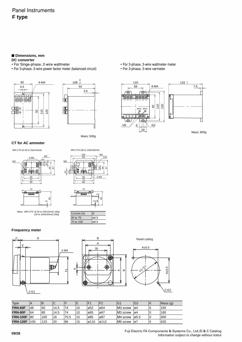
Fuji Electric FA Components & Systems Co., Ltd./D & C CatalogInformation subject to change without notice09/28
Dimensions, mmDC converter• For Singe-phase, 2-wire wattmeter• For 3-phase, 3-wire power factor meter (balanced circuit)
• For 3-phase, 3-wire wattmeter meter• For 3-phase, 3-wire varmeter
CT for AC ammeter
Mass: 500g
6-M4
120
110
92
4.5
56
6092
108 0-2
3.5
6
5
1 2 3 4
Mass: 800g
R36
110
29
VR
58
92 110
120
133 +1-2
9-M4 7.5
MAX.
M+ M–
P1 3S1LP3 1S
BIAS
3LP2
k
K
l L
MR-CTN (0.35 to 25A/10mA)
Mass: MR-CTN (0.35 to 25A/10mA) 160g (30 to 100A/20mA) 200g
M3
72
5744
60
55
8072
4-M4
M3
35
12
K
k l L
MR-CTN (30 to 100A/20mA)
80
72
234
55
3
10084
6072
12 5
M3
M32-D
2-M4
574416
Frequency meter
F2+0.5
0
A±
0.5K BA
Panel cutting
2-M4
E
C
2-G1
D
A±0.5A
35
2-G2
B
F1
Current (A) D
30 to 70 ø6.5
75 to 100 ø8.5
Type A B C D E F1 F2 G1 G2 K Mass (g)FRN-60F 48 60 14.5 74 10 ø52 ø54 M3 screw ø4 6 150FRN-80F 64 80 14.5 74 10 ø65 ø67 M3 screw ø4 0 180FRN-100F 80 100 16 75.5 15 ø85 ø87 M4 screw ø5.5 0 300FRN-120F 100 123 20 86 15 ø110 ø112 M5 screw ø7 0 420
Panel InstrumentsF type
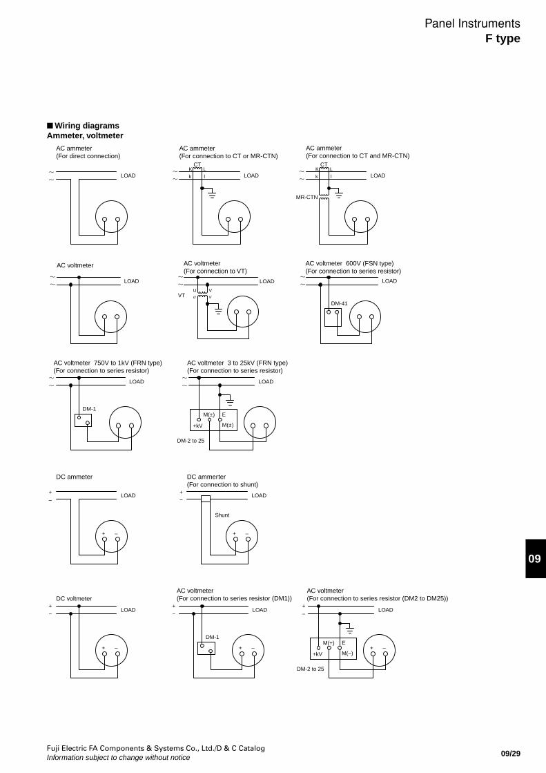
Fuji Electric FA Components & Systems Co., Ltd./D & C CatalogInformation subject to change without notice 09/29
09
Wiring diagramsAmmeter, voltmeter
LOAD
AC ammeter(For direct connection)
LOADK L
k l
CT
AC ammeter(For connection to CT or MR-CTN)
LOAD
+ –
DC ammeter
–+
−+
−+
LOAD
+ –
DC ammerter (For connection to shunt)
Shunt
−+
LOAD
MR-CTN
K L
k l
CT
AC ammeter(For connection to CT and MR-CTN)
LOAD
+ –
DC voltmeter
LOAD LOAD
DM-1
–+
DM-2 to 25
+kV
M(+)
M(–)
E+ –
AC voltmeter(For connection to series resistor (DM1))
AC voltmeter(For connection to series resistor (DM2 to DM25))
–+
AC voltmeter
LOAD
AC voltmeter(For connection to VT)
VT uU
vV
LOAD
DM-41
AC voltmeter 600V (FSN type)(For connection to series resistor)
LOAD
LOAD LOAD
DM-1
DM-2 to 25
+kV
M(±)
M(±)
E
AC voltmeter 750V to 1kV (FRN type)(For connection to series resistor)
AC voltmeter 3 to 25kV (FRN type)(For connection to series resistor)
Panel InstrumentsF type
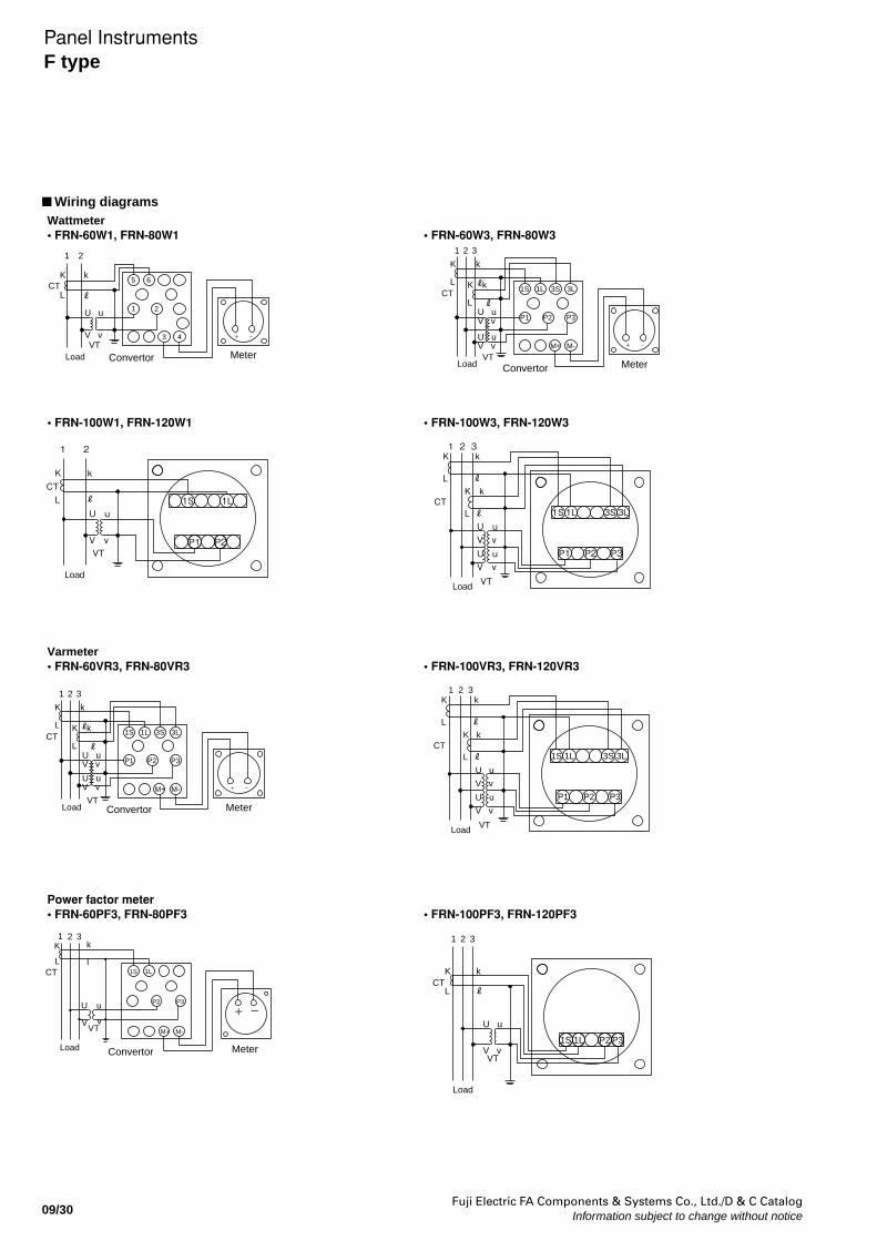
Fuji Electric FA Components & Systems Co., Ltd./D & C CatalogInformation subject to change without notice09/30
Wiring diagrams
Load
1 2
+ −
VT
K k
L
U u
V v
CT
Convertor Meter
5 6
1 2
3 4
1S 1L 3S 3L
P3P2P1
Load
1 2 3
+ −
VT
K k
L K k
L U uV v
U uV v
CT
Convertor Meter
M+ M-
Load
1 2 3K k
LK k
LU uV vU uV v
CT
VT
P1 P2 P3
3L3S1L1S
Load
K k
LU u
V v
1 2
CT
VT
1S
P1 P2
1L
1S 1L 3S 3L
P3P2P1
Load
Load
1 2 3
+ −
VT
K k
L K k
L U uV v
U uV v
CT
Convertor Meter
Meter
M+ M-
ℓ
Load
1 2 3K k
LK k
L
U u
V v
U u
V v
CT
VT
P1 P2 P3
3L3S1L1S
+U
VM-
Convertor
VTv
u
M+
-
LCT
K1 32
P3
l1S 1L
k
P2
Load
VT
K k
L
1L P2 P31S
U u
V v
1 2 3
CT
Wattmeter• FRN-60W1, FRN-80W1 • FRN-60W3, FRN-80W3
Varmeter• FRN-60VR3, FRN-80VR3 • FRN-100VR3, FRN-120VR3
Power factor meter• FRN-60PF3, FRN-80PF3 • FRN-100PF3, FRN-120PF3
• FRN-100W1, FRN-120W1 • FRN-100W3, FRN-120W3
Panel InstrumentsF type
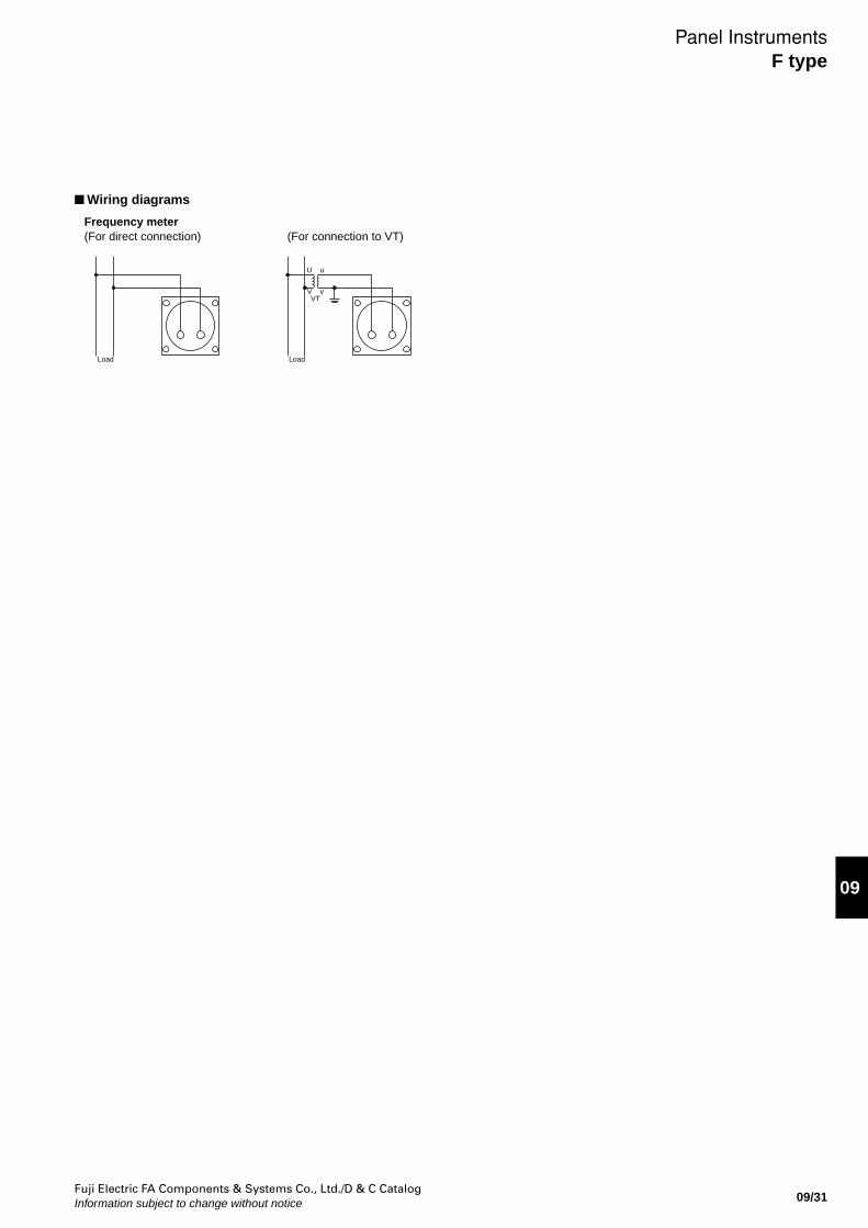
Fuji Electric FA Components & Systems Co., Ltd./D & C CatalogInformation subject to change without notice 09/31
09
Wiring diagrams
Frequency meter(For direct connection) (For connection to VT)
Load
U u
V vVT
Load
Panel InstrumentsF type
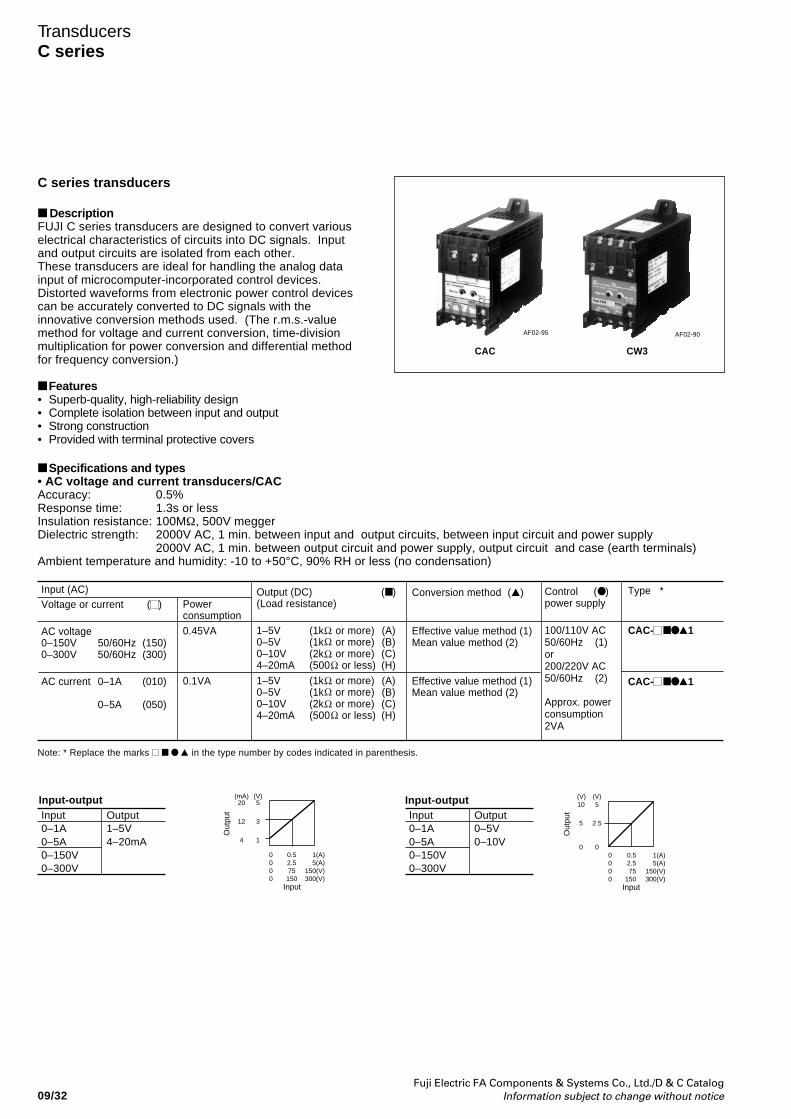
Fuji Electric FA Components & Systems Co., Ltd./D & C CatalogInformation subject to change without notice09/32
TransducersC series
C series transducers
DescriptionFUJI C series transducers are designed to convert variouselectrical characteristics of circuits into DC signals. Inputand output circuits are isolated from each other.These transducers are ideal for handling the analog datainput of microcomputer-incorporated control devices.Distorted waveforms from electronic power control devicescan be accurately converted to DC signals with theinnovative conversion methods used. (The r.m.s.-valuemethod for voltage and current conversion, time-divisionmultiplication for power conversion and differential methodfor frequency conversion.)
Features• Superb-quality, high-reliability design• Complete isolation between input and output• Strong construction• Provided with terminal protective covers
Input (AC)Voltage or current ( )
AC voltage0–150V 50/60Hz (150)0–300V 50/60Hz (300)
AC current 0–1A (010)
0–5A (050)
Conversion method ()
Effective value method (1)Mean value method (2)
Effective value method (1)Mean value method (2)
Type *
CAC- 1
CAC- 1
Control ( )power supply
100/110V AC50/60Hz (1)or200/220V AC50/60Hz (2)
Approx. powerconsumption2VA
CAC CW3
AF02-95 AF02-90
Output (DC) ( )(Load resistance)
1–5V (1k or more) (A)0–5V (1k or more) (B)0–10V (2k or more) (C)4–20mA (500 or less) (H)
1–5V (1k or more) (A)0–5V (1k or more) (B)0–10V (2k or more) (C)4–20mA (500 or less) (H)
Powerconsumption0.45VA
0.1VA
Input-outputInput0–1A0–5A0–150V0–300V
Output1–5V4–20mA
Input0–1A0–5A0–150V0–300V
Output0–5V0–10V
0 0.5 1(A)0 2.5 5(A)0 75 150(V)0 150 300(V)
(mA) (V)20 5
12 3
4 1
Out
put
Input
0 0.5 1(A)0 2.5 5(A)0 75 150(V)0 150 300(V)
(V) (V)10 5
5 2.5
0 0
Out
put
Input
Input-output
Specifications and types• AC voltage and current transducers/CACAccuracy: 0.5%Response time: 1.3s or lessInsulation resistance: 100MΩ, 500V meggerDielectric strength: 2000V AC, 1 min. between input and output circuits, between input circuit and power supply
2000V AC, 1 min. between output circuit and power supply, output circuit and case (earth terminals)Ambient temperature and humidity: -10 to +50°C, 90% RH or less (no condensation)
Note: * Replace the marks in the type number by codes indicated in parenthesis.
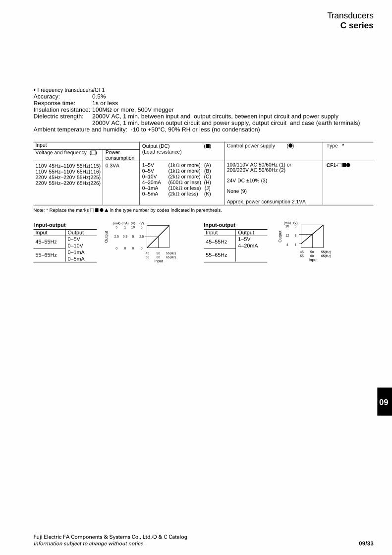
Fuji Electric FA Components & Systems Co., Ltd./D & C CatalogInformation subject to change without notice 09/33
09
TransducersC series
InputVoltage and frequency ( )
110V 45Hz–110V 55Hz(115)110V 55Hz–110V 65Hz(116)220V 45Hz–220V 55Hz(225)220V 55Hz–220V 65Hz(226)
Control power supply ( )
100/110V AC 50/60Hz (1) or200/220V AC 50/60Hz (2)
24V DC ±10% (3)
None (9)
Approx. power consumption 2.1VA
Type *
CF1-
Output (DC) ( )(Load resistance)
1–5V (1k or more) (A)0–5V (1k or more) (B)0–10V (2k or more) (C)4–20mA (600 or less) (H)0–1mA (10k or less) (J)0–5mA (2k or less) (K)
Powerconsumption0.3VA
Input-outputInput
45–55Hz
55–65Hz
Output0–5V0–10V0–1mA0–5mA
Input
45–55Hz
55–65Hz
Output1–5V4–20mA
45 50 55(Hz)55 60 65(Hz)
(mA) (mA) (V) (V)5 1 10 5
2.5 0.5 5 2.5
0 0 0 0
Out
put
Input
45 50 55(Hz)55 60 65(Hz)
Input
(mA) (V)20 5
12 3
4 1
Out
put
Input-output
• Frequency transducers/CF1Accuracy: 0.5%Response time: 1s or lessInsulation resistance: 100MΩ or more, 500V meggerDielectric strength: 2000V AC, 1 min. between input and output circuits, between input circuit and power supply
2000V AC, 1 min. between output circuit and power supply, output circuit and case (earth terminals)Ambient temperature and humidity: -10 to +50°C, 90% RH or less (no condensation)
Note: * Replace the marks in the type number by codes indicated in parenthesis.
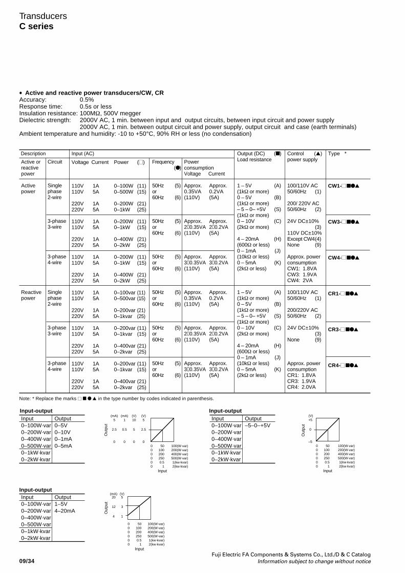
Fuji Electric FA Components & Systems Co., Ltd./D & C CatalogInformation subject to change without notice09/34
TransducersC series
•
Circuit
Singlephase2-wire
3-phase3-wire
3-phase4-wire
Singlephase2-wire
3-phase3-wire
3-phase4-wire
Type *
CW1-
CW3-
CW4-
CR1-
CR3-
CR4-
Activepower
Reactivepower
Frequency ( )
50Hz (5)or60Hz (6)
50Hz (5)or60Hz (6)
50Hz (5)or60Hz (6)
50Hz (5)or60Hz (6)
50Hz (5)or60Hz (6)
50Hz (5)or60Hz (6)
PowerconsumptionVoltage Current
Approx. Approx.0.35VA 0.2VA(110V) (5A)
Approx. Approx.2×0.35VA 2×0.2VA(110V) (5A)
Approx. Approx.3×0.35VA 3×0.2VA(110V) (5A)
Approx. Approx.0.35VA 0.2VA(110V) (5A)
Approx. Approx.2×0.35VA 2×0.2VA(110V) (5A)
Approx. Approx.3×0.35VA 3×0.2VA(110V) (5A)
Output (DC) ( )Load resistance
1 – 5V (A)(1kΩ or more)0 – 5V (B)(1kΩ or more)– 5 – 0– +5V (S)(1kΩ or more)0 – 10V (C)(2kΩ or more)
4 – 20mA (H)(600Ω or less)0 – 1mA (J)(10kΩ or less)0 – 5mA (K)(2kΩ or less)
1 – 5V (A)(1kΩ or more)0 – 5V (B)(1kΩ or more)– 5 – 0– +5V (S)(1kΩ or more)0 – 10V (C)(2kΩ or more)
4 – 20mA (H)(600Ω or less)0 – 1mA (J)(10kΩ or less)0 – 5mA (K)(2kΩ or less)
Control ()power supply
100/110V AC50/60Hz (1)
200/ 220V AC50/60Hz (2)
24V DC±10%(3)
110V DC±10%Except CW4(4)None (9)
Approx. powerconsumptionCW1: 1.8VACW3: 1.9VACW4: 2VA
100/110V AC50/60Hz (1)
200/220V AC50/60Hz (2)
24V DC±10%(3)
None (9)
Approx. powerconsumptionCR1: 1.8VACR3: 1.9VACR4: 2.0VA
Input (AC)
Voltage Current Power ( )
110V 1A 0–100W (11)110V 5A 0–500W (15)
220V 1A 0–200W (21)220V 5A 0–1kW (25)
110V 1A 0–200W (11)110V 5A 0–1kW (15)
220V 1A 0–400W (21)220V 5A 0–2kW (25)
110V 1A 0–200W (11)110V 5A 0–1kW (15)
220V 1A 0–400W (21)220V 5A 0–2kW (25)
110V 1A 0–100var (11)110V 5A 0–500var (15)
220V 1A 0–200var (21)220V 5A 0–1kvar (25)
110V 1A 0–200var (11)110V 5A 0–1kvar (15)
220V 1A 0–400var (21)220V 5A 0–2kvar (25)
110V 1A 0–200var (11)110V 5A 0–1kvar (15)
220V 1A 0–400var (21)220V 5A 0–2kvar (25)
Active orreactivepower
Input0–100W·var0–200W·var0–400W·var0–500W·var0–1kW·kvar0–2kW·kvar
Output0–5V0–10V0–1mA0–5mA
Input-outputInput0–100W·var0–200W·var0–400W·var0–500W·var0–1kW·kvar0–2kW·kvar
Output–5–0–+5V
Input0–100W·var0–200W·var0–400W·var0–500W·var0–1kW·kvar0–2kW·kvar
Output1–5V4–20mA
0 50 100(W·var)0 100 200(W·var)0 200 400(W·var)0 250 500(W·var)0 0.5 1(kw·kvar)0 1 2(kw·kvar)
(mA) (mA) (V) (V)5 1 10 5
2.5 0.5 5 2.5
0 0 0 0
Out
put
Input
0 50 100(W·var)0 100 200(W·var)0 200 400(W·var)0 250 500(W·var)0 0.5 1(kw·kvar)0 1 2(kw·kvar)
(V)+5
0
–5
Out
put
Input
Input-output
Input-output
0 50 100(W·var)0 100 200(W·var)0 200 400(W·var)0 250 500(W·var)0 0.5 1(kw·kvar)0 1 2(kw·kvar)
Input
(mA)20 5
12 3
4 1
(V)
Out
put
Description
Note: * Replace the marks in the type number by codes indicated in parenthesis.
Active and reactive power transducers/CW, CRAccuracy: 0.5%Response time: 0.5s or lessInsulation resistance: 100MΩ, 500V meggerDielectric strength: 2000V AC, 1 min. between input and output circuits, between input circuit and power supply
2000V AC, 1 min. between output circuit and power supply, output circuit and case (earth terminals)Ambient temperature and humidity: -10 to +50°C, 90% RH or less (no condensation)
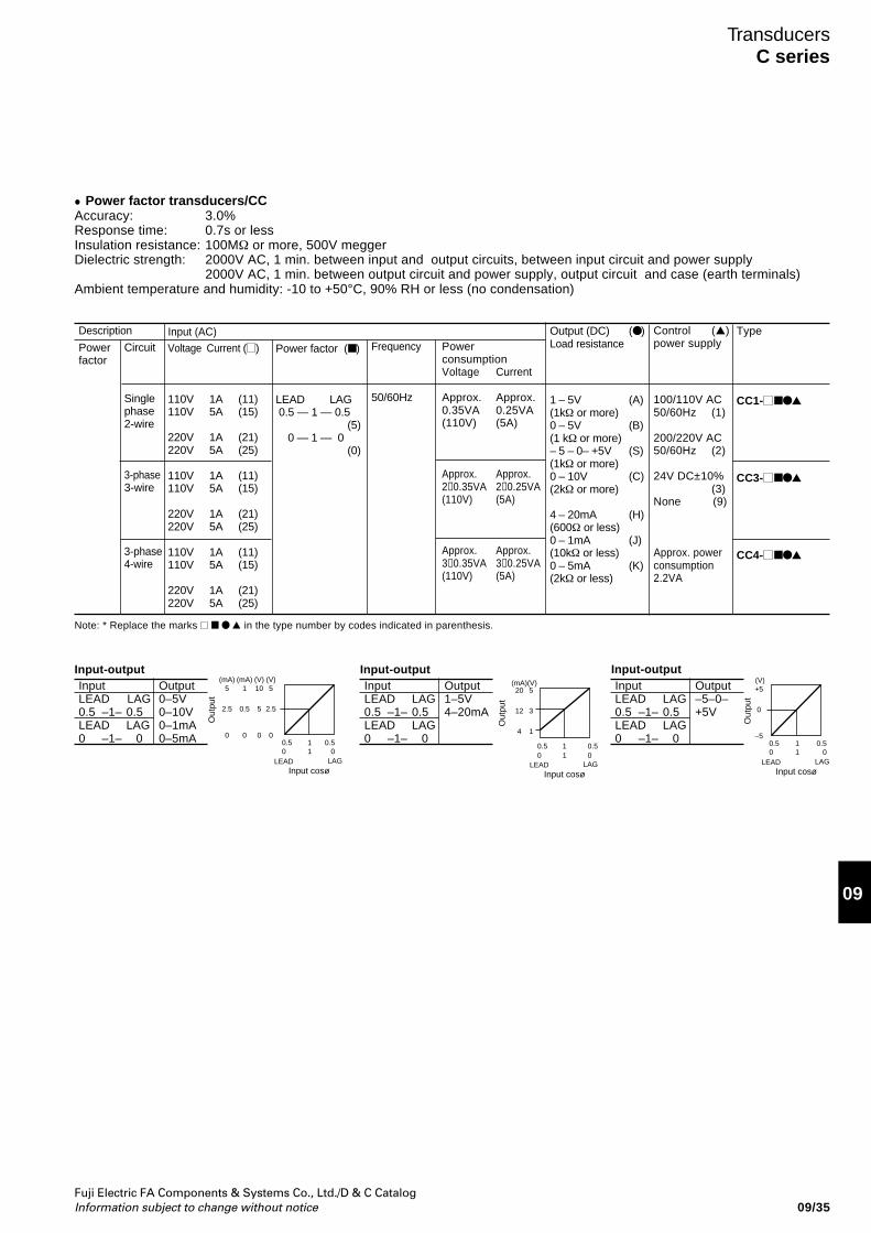
Fuji Electric FA Components & Systems Co., Ltd./D & C CatalogInformation subject to change without notice 09/35
09
TransducersC series
Power factor transducers/CCAccuracy: 3.0%Response time: 0.7s or lessInsulation resistance: 100MΩ or more, 500V meggerDielectric strength: 2000V AC, 1 min. between input and output circuits, between input circuit and power supply
2000V AC, 1 min. between output circuit and power supply, output circuit and case (earth terminals)Ambient temperature and humidity: -10 to +50°C, 90% RH or less (no condensation)
•
Powerfactor
Input (AC)Circuit
Singlephase2-wire
3-phase3-wire
3-phase4-wire
Voltage Current ( )
110V 1A (11)110V 5A (15)
220V 1A (21)220V 5A (25)
110V 1A (11)110V 5A (15)
220V 1A (21)220V 5A (25)
110V 1A (11)110V 5A (15)
220V 1A (21)220V 5A (25)
Control ()power supply
100/110V AC50/60Hz (1)
200/220V AC50/60Hz (2)
24V DC±10%(3)
None (9)
Approx. powerconsumption2.2VA
Type
CC1-
CC3-
CC4-
Output (DC) ( )Load resistance
1 – 5V (A)(1kΩ or more)0 – 5V (B)(1 kΩ or more)– 5 – 0– +5V (S)(1kΩ or more)0 – 10V (C)(2kΩ or more)
4 – 20mA (H)(600Ω or less)0 – 1mA (J)(10kΩ or less)0 – 5mA (K)(2kΩ or less)
PowerconsumptionVoltage Current
Approx. Approx.0.35VA 0.25VA(110V) (5A)
Approx. Approx.2×0.35VA 2×0.25VA(110V) (5A)
Approx. Approx.3×0.35VA 3×0.25VA(110V) (5A)
Frequency
50/60Hz
Power factor ( )
LEAD LAG 0.5 — 1 — 0.5
(5) 0 — 1 — 0
(0)
Input-outputInputLEAD LAG0.5 –1– 0.5LEAD LAG0 –1– 0
Output0–5V0–10V0–1mA0–5mA
InputLEAD LAG0.5 –1– 0.5LEAD LAG0 –1– 0
Output1–5V4–20mA
InputLEAD LAG0.5 –1– 0.5LEAD LAG0 –1– 0
Output–5–0–+5V
0.5 1 0.50 1 0
(mA) (mA) (V) (V)5 1 10 5
2.5 0.5 5 2.5
0 0 0 0
Out
put
Input cosøLEAD LAG
0.5 1 0.50 1 0
(V)+5
0
–5
Out
put
Input cosøLEAD LAG
Input-output Input-output(mA)(V)20 5
12 3
4 1
Out
put
Input cosøLEAD LAG
0.5 1 0.50 1 0
Description
Note: * Replace the marks in the type number by codes indicated in parenthesis.
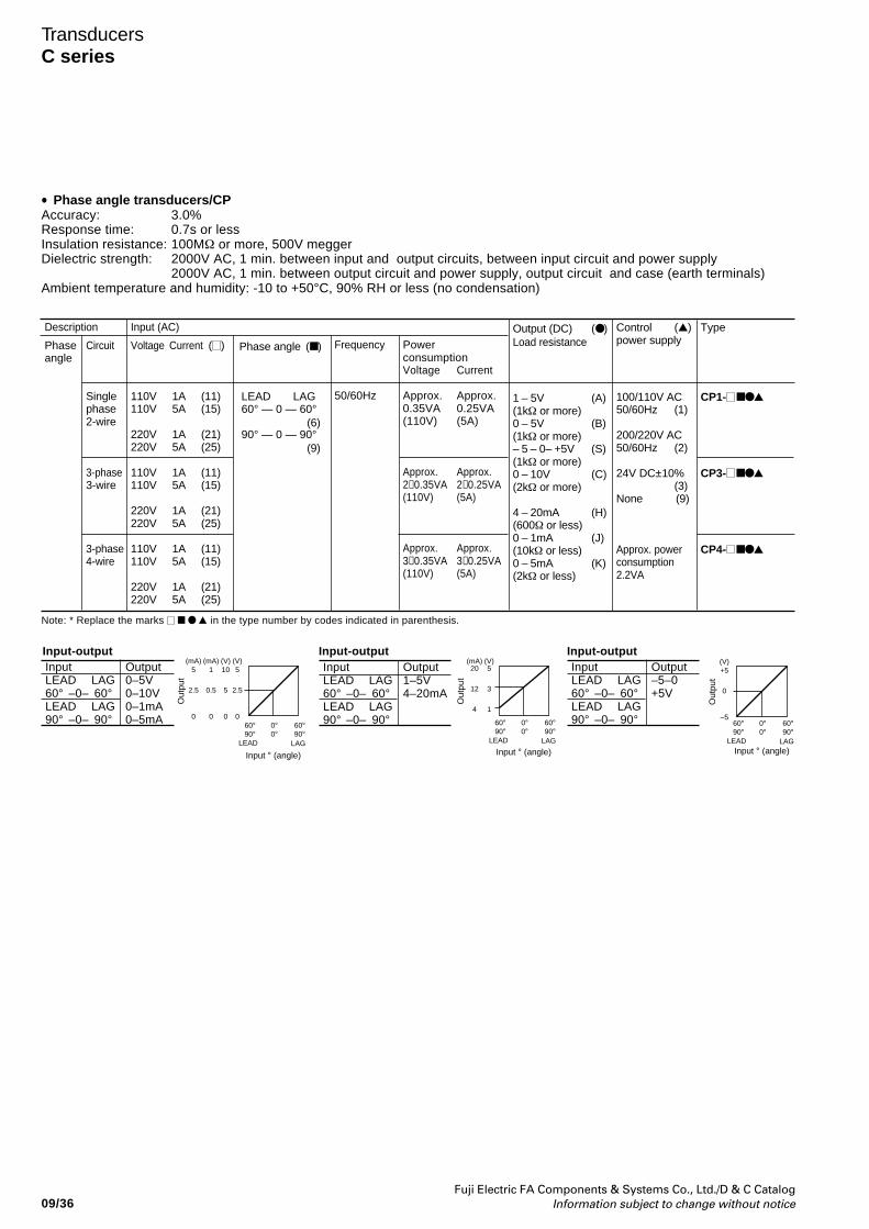
Fuji Electric FA Components & Systems Co., Ltd./D & C CatalogInformation subject to change without notice09/36
TransducersC series
Phase angle transducers/CPAccuracy: 3.0%Response time: 0.7s or lessInsulation resistance: 100MΩ or more, 500V meggerDielectric strength: 2000V AC, 1 min. between input and output circuits, between input circuit and power supply
2000V AC, 1 min. between output circuit and power supply, output circuit and case (earth terminals)Ambient temperature and humidity: -10 to +50°C, 90% RH or less (no condensation)
•
Input (AC)
Voltage Current ( )
110V 1A (11)110V 5A (15)
220V 1A (21)220V 5A (25)
110V 1A (11)110V 5A (15)
220V 1A (21)220V 5A (25)
110V 1A (11)110V 5A (15)
220V 1A (21)220V 5A (25)
Circuit
Singlephase2-wire
3-phase3-wire
3-phase4-wire
Phaseangle
Control ()power supply
100/110V AC50/60Hz (1)
200/220V AC50/60Hz (2)
24V DC±10%(3)
None (9)
Approx. powerconsumption2.2VA
Type
CP1-
CP3-
CP4-
Output (DC) ( )Load resistance
1 – 5V (A)(1kΩ or more)0 – 5V (B)(1kΩ or more)– 5 – 0– +5V (S)(1kΩ or more)0 – 10V (C)(2kΩ or more)
4 – 20mA (H)(600Ω or less)0 – 1mA (J)(10kΩ or less)0 – 5mA (K)(2kΩ or less)
PowerconsumptionVoltage Current
Approx. Approx.0.35VA 0.25VA(110V) (5A)
Approx. Approx.2×0.35VA 2×0.25VA(110V) (5A)
Approx. Approx.3×0.35VA 3×0.25VA(110V) (5A)
Frequency
50/60HzLEAD LAG60° — 0 — 60°
90° — 0 — 90°
Phase angle ( )
(6)
(9)
Input-outputInputLEAD LAG60° –0– 60°LEAD LAG90° –0– 90°
Output0–5V0–10V0–1mA0–5mA
InputLEAD LAG60° –0– 60°LEAD LAG90° –0– 90°
Output1–5V4–20mA
InputLEAD LAG60° –0– 60°LEAD LAG90° –0– 90°
Output–5–0+5V
(mA) (mA) (V) (V)5 1 10 5
2.5 0.5 5 2.5
0 0 0 0
Out
put
60° 0° 60°90° 0° 90°
LEAD LAG
Input ° (angle)
(mA) (V)20 5
12 3
4 1
Out
put
60° 0° 60°90° 0° 90°
LEAD LAG
Input ° (angle)
(V)+5
0
–560° 0° 60°90° 0° 90°
LEAD LAG
Out
put
Input ° (angle)
Input-output Input-output
Description
Note: * Replace the marks in the type number by codes indicated in parenthesis.
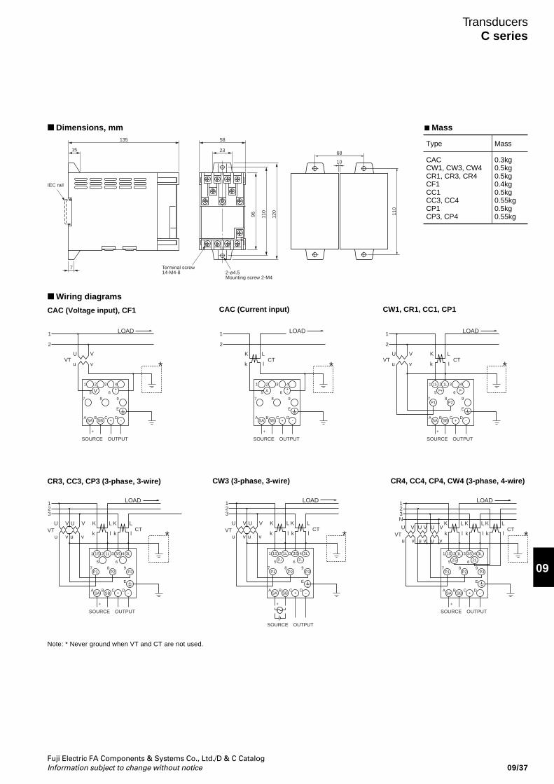
Fuji Electric FA Components & Systems Co., Ltd./D & C CatalogInformation subject to change without notice 09/37
09
TransducersC series
Mass
Type
CACCW1, CW3, CW4CR1, CR3, CR4CF1CC1CC3, CC4CP1CP3, CP4
Mass
0.3kg0.5kg0.5kg0.4kg0.5kg0.55kg0.5kg0.55kg
Dimensions, mm
CAC (Voltage input), CF1 CAC (Current input) CW1, CR1, CC1, CP1
Wiring diagrams
CR3, CC3, CP3 (3-phase, 3-wire) CW3 (3-phase, 3-wire) CR4, CC4, CP4, CW4 (3-phase, 4-wire)
V VU U
123
VTvu vu
LK
lk
LOAD
1 2 3 4
6
+
+
–
5
987
A BSA SB
C D
E
P+ P–
P1
1S 1L 3S 3L
P2 P3
OUTPUTSOURCE
LKCT
lk *
V
*U
VTvu
LOAD
1 2 3 4
6+-
+
+
-
5
987
A BSA SB
C D
E
V
OUTPUTSOURCE
1
2
LKCT
lk
LOAD
1 2 3 4
6+-
+
+
-
5
987
A BSA SB
C D
E
A
OUTPUTSOURCE
1
2
*VU
VTvu
LKCT
lk
LOAD
1 2 3 4
6
+
+
-
5
987
A BSA SB
C D
E
P+ P-
1S 1L
P1 P2
OUTPUTSOURCE
1
2
*
V VU U
123
VTvu vu
LK
lk
LOAD
1 2 3 4
6
+
+
-
5
987
A BSA SB
C D
E
P1
1S 1L 3S 3L
P2 P3
OUTPUTSOURCE
LKCT
lk *V V VU U U
123N
VTvu v vu u
LK
lk
LOAD
1 2 3 4
6
+
+
-
5
987
A BSA SB
C D
E
P1
1S 1L
2S 2L
3S 3L
P2 P3
OUTPUTSOURCE
LK
lk
LKCT
lk *
Note: * Never ground when VT and CT are not used.
68
10
110
E
15
IEC rail
58
23
135
120
110
96
Terminal screw14-M4-8 2-ø4.5
Mounting screw 2-M4
7
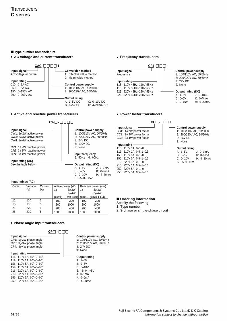
Fuji Electric FA Components & Systems Co., Ltd./D & C CatalogInformation subject to change without notice09/38
TransducersC series
Type number nomenclature
Active and reactive power transducers
CW -
Input signalCW1: 1φ 2W active powerCW3: 3φ 3W active powerCW4: 3φ 4W active power
CR1: 1φ 2W reactive powerCR3: 3φ 3W reactive powerCR4: 3φ 4W reactive power
Input rating (AC)See the table below.
Control power supply1: 100/110V AC, 50/60Hz2: 200/220V AC, 50/60Hz3: 24V DC4: 110V DC9: None
Input frequency5: 50Hz 6: 60Hz
Output rating (DC)A: 1–5V J: 0–1mAB: 0–5V K: 0–5mAC: 0–10V H: 4–20mAS: –5–0– +5V
Input signalAC voltage or current
Input rating010: 0–1A AC050: 0–5A AC150: 0–150V AC300: 0–300V AC
CAC- 1
•
•
CF1-
•
Power factor transducers
Input signalCC1: 1φ 2W power factorCC3: 3φ 3W power factorCC4: 3φ 4W power factor
Input rating110: 110V 1A, 0–1–0115: 110V 1A, 0.5–1–0.5150: 110V 5A, 0–1–0155: 110V 5A, 0.5–1–0.5210: 220V 1A, 0–1–0215: 220V 1A, 0.5–1–0.5250: 220V 5A, 0–1–0255: 220V 5A, 0.5–1–0.5
CC -
•
Frequency transducers
Control power supply1: 100/110V AC, 50/60Hz2: 200/220V AC, 50/60Hz3: 24V DC9: None
Output ratingA: 1–5V J: 0–1mAB: 0–5V K: 0–5mAC: 0–10V H: 4–20mAS: –5–0–+5V
Input signalFrequency
Input rating115: 110V 45Hz–110V 55Hz116: 110V 55Hz–110V 65Hz225: 220V 45Hz–220V 55Hz226: 220V 55Hz–220V 65Hz
Control power supply1: 100/110V AC, 50/60Hz2: 200/220V AC, 50/60Hz3: 24V DC9: None
Output rating (DC)A: 1–5V J: 0–1mAB: 0–5V K: 0–5mAC: 0–10V H: 4–20mA
Code
11152125
Voltage Current(V) (A)
110 1110 5220 1220 5
Active power (W)1φ 3φ 3W
3φ 4W(CW1) (CW3, CW4)
100 200500 1000200 400
1000 2000
Reactive power (var)1φ 3φ 3W
3φ 4W(CR1) (CR3, CR4)
100 200500 1000200 400
1000 2000
Input ratings (AC)
• Phase angle input transducers
Input signalCP1: 1φ 2W phase angleCP3: 3φ 3W phase angleCP4: 3φ 4W phase angle
Input rating116: 110V 1A, 60°–0–60°119: 110V 1A, 90°–0–90°156: 110V 5A, 60°–0–60°159: 110V 5A, 90°–0–90°216: 220V 1A, 60°–0–60°219: 220V 1A, 90°–0–90°256: 220V 5A, 60°–0–60°259: 220V 5A, 90°–0–90°
CP - Control power supply1: 100/110V AC, 50/60Hz2: 200/220V AC, 50/60Hz3: 24V DC9: None
Output ratingA: 1–5VB: 0–5VC: 0–10VS: –5–0– +5VJ: 0–1mAK: 0–5mAH: 4–20mA
Ordering informationSpecify the following:1. Type number2. 3-phase or single-phase circuit
Conversion method1: Effective value method2: Mean value method
Control power supply1: 100/110V AC, 50/60Hz2: 200/220V AC, 50/60Hz
Output ratingA: 1–5V DC C: 0–10V DCB: 0–5V DC H: 4–20mA DC
AC voltage and current transducers
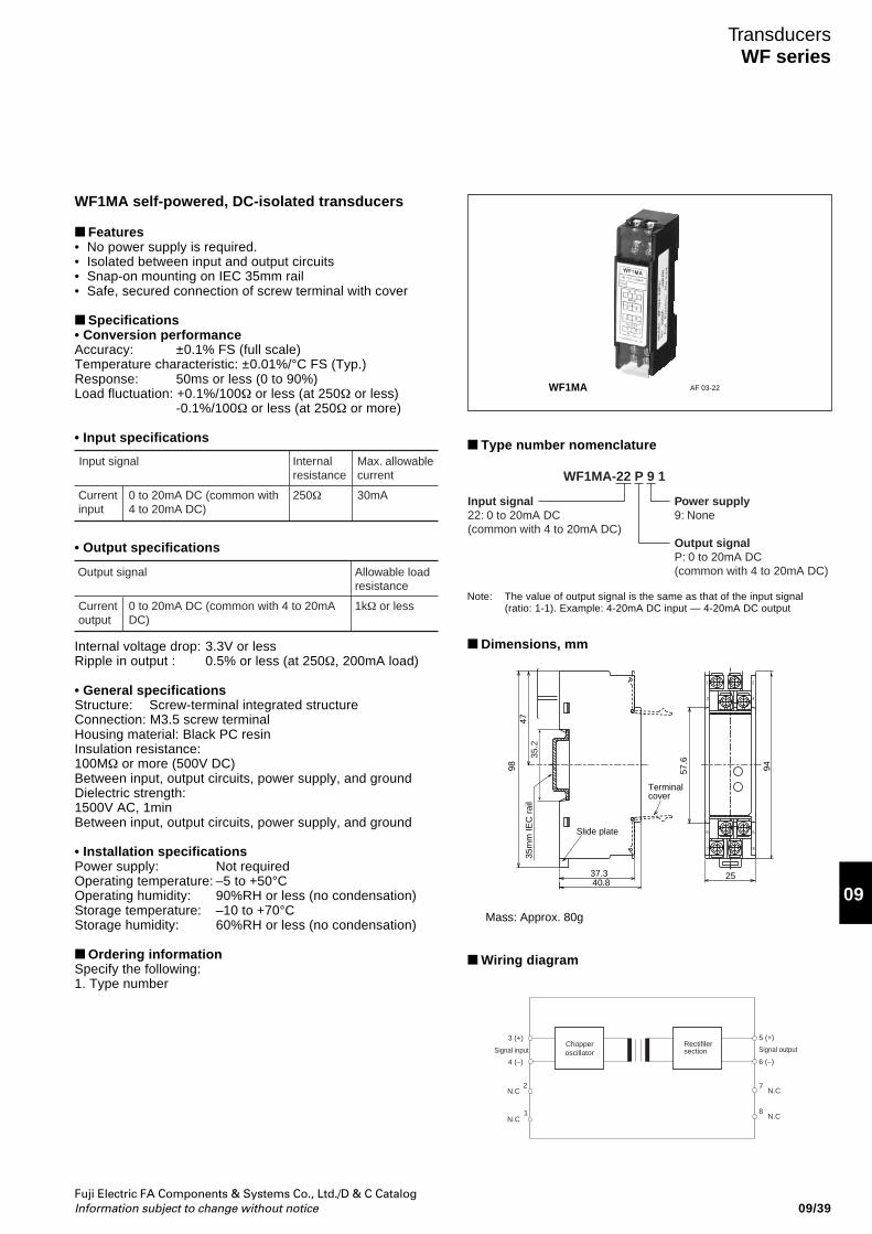
Fuji Electric FA Components & Systems Co., Ltd./D & C CatalogInformation subject to change without notice 09/39
09
TransducersWF series
WF1MA AF 03-22
WF1MA self-powered, DC-isolated transducers
Features• No power supply is required.• Isolated between input and output circuits• Snap-on mounting on IEC 35mm rail• Safe, secured connection of screw terminal with cover
Specifications• Conversion performanceAccuracy: ±0.1% FS (full scale)Temperature characteristic: ±0.01%/°C FS (Typ.)Response: 50ms or less (0 to 90%)Load fluctuation: +0.1%/100Ω or less (at 250Ω or less)
-0.1%/100Ω or less (at 250Ω or more)
• Input specifications
Input signal Internal resistance
Max. allowable current
0 to 20mA DC (common with 4 to 20mA DC)
Current input
250Ω 30mA
• Output specifications
Output signal Allowable load resistance
0 to 20mA DC (common with 4 to 20mA DC)
Current output
1kΩ or less
Internal voltage drop: 3.3V or lessRipple in output : 0.5% or less (at 250Ω, 200mA load)
• General specificationsStructure: Screw-terminal integrated structureConnection: M3.5 screw terminalHousing material: Black PC resinInsulation resistance:100MΩ or more (500V DC)Between input, output circuits, power supply, and groundDielectric strength:1500V AC, 1minBetween input, output circuits, power supply, and ground
• Installation specificationsPower supply: Not requiredOperating temperature: –5 to +50°COperating humidity: 90%RH or less (no condensation)Storage temperature: –10 to +70°CStorage humidity: 60%RH or less (no condensation)
Ordering informationSpecify the following:1. Type number
Type number nomenclature
Input signal22: 0 to 20mA DC(common with 4 to 20mA DC)
Power supply9: None
Output signalP: 0 to 20mA DC(common with 4 to 20mA DC)
WF1MA-22 P 9 1
Note: The value of output signal is the same as that of the input signal(ratio: 1-1). Example: 4-20mA DC input — 4-20mA DC output
Dimensions, mm
Wiring diagram
35.2
1 2
43
7 8
65
94
25
57.6
35m
m IE
C r
ail
37.340.8
9847
Terminal cover
Slide plate
Mass: Approx. 80g
Rectifilersection
Chopperoscillator
1
2
3 (+)
4 (–)
N.C
N.C
N.C
N.C
5 (+)
6 (–)
7
8
Signal input Signal output
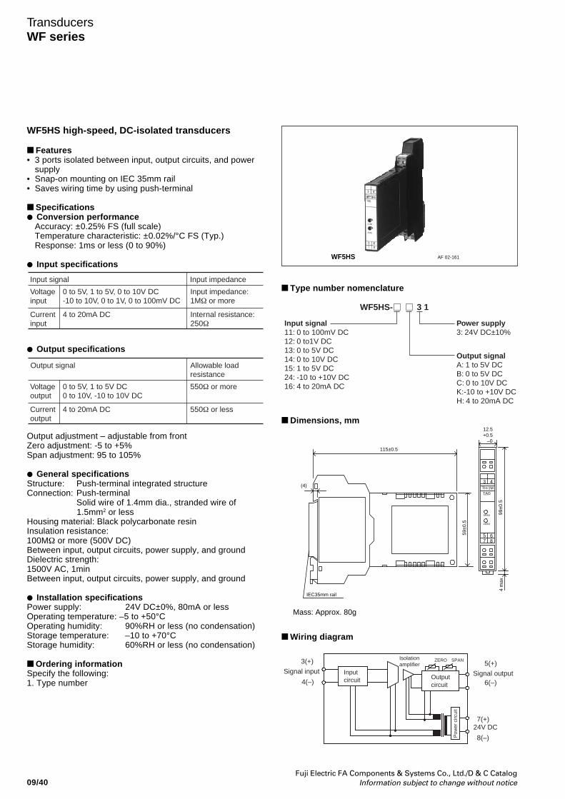
Fuji Electric FA Components & Systems Co., Ltd./D & C CatalogInformation subject to change without notice09/40
TransducersWF series
WF5HS high-speed, DC-isolated transducers
Features• 3 ports isolated between input, output circuits, and power
supply• Snap-on mounting on IEC 35mm rail• Saves wiring time by using push-terminal
Specifications Conversion performance
Accuracy: ±0.25% FS (full scale)Temperature characteristic: ±0.02%/°C FS (Typ.)Response: 1ms or less (0 to 90%)
Input specifications
Input signal Input impedance
0 to 5V, 1 to 5V, 0 to 10V DC-10 to 10V, 0 to 1V, 0 to 100mV DC
Input impedance:1MΩ or more
Voltage input
4 to 20mA DC Internal resistance: 250Ω
Current input
Output specifications
Output adjustment – adjustable from frontZero adjustment: -5 to +5%Span adjustment: 95 to 105%
General specificationsStructure: Push-terminal integrated structureConnection: Push-terminal
Solid wire of 1.4mm dia., stranded wire of1.5mm2 or less
Housing material: Black polycarbonate resinInsulation resistance:100MΩ or more (500V DC)Between input, output circuits, power supply, and groundDielectric strength:1500V AC, 1minBetween input, output circuits, power supply, and ground
Installation specificationsPower supply: 24V DC±0%, 80mA or lessOperating temperature: –5 to +50°COperating humidity: 90%RH or less (no condensation)Storage temperature: –10 to +70°CStorage humidity: 60%RH or less (no condensation)
Ordering informationSpecify the following:1. Type number
Output signal Allowable load resistance
0 to 5V, 1 to 5V DC0 to 10V, -10 to 10V DC
550Ω or moreVoltage output
4 to 20mA DC 550Ω or lessCurrent output
Type number nomenclature
Dimensions, mm
Wiring diagram
WF5HS AF 02-161
Input signal11: 0 to 100mV DC12: 0 to1V DC13: 0 to 5V DC14: 0 to 10V DC15: 1 to 5V DC24: -10 to +10V DC16: 4 to 20mA DC
Power supply3: 24V DC±10%
Output signalA: 1 to 5V DCB: 0 to 5V DCC: 0 to 10V DCK:-10 to +10V DCH: 4 to 20mA DC
WF5HS- 3 1
99±0
.5
43
6587
SPAN
ZERO
TAGTH-1M
4 m
ax
12.5+0.5
–0
59±0
.5
115±0.5
(4)
IEC35mm rail
Mass: Approx. 80g
Signal outputInputcircuit
Signal input
3(+)
4(–) 6(–)
24V DC
5(+)
8(–)
7(+)
Outputcircuit
ZERO SPANIsolationamplifier
Pow
er c
ircui
t
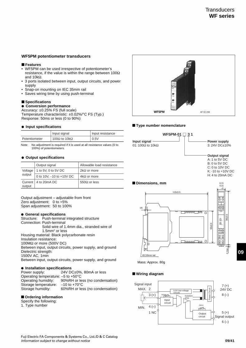
Fuji Electric FA Components & Systems Co., Ltd./D & C CatalogInformation subject to change without notice 09/41
09
TransducersWF series
WF5PM potentiometer transducers
Features• WF5PM can be used irrespective of potentiometer’s
resistance, if the value is within the range between 100Ωand 10kΩ.
• 3 ports isolated between input, output circuits, and powersupply
• Snap-on mounting on IEC 35mm rail• Saves wiring time by using push-terminal
Specifications Conversion performanceAccuracy: ±0.25% FS (full scale)Temperature characteristic: ±0.02%/°C FS (Typ.)Response: 50ms or less (0 to 90%)
Input specifications
Output specifications
Output adjustment – adjustable from frontZero adjustment: 0 to +5%Span adjustment: 50 to 100%
General specificationsStructure: Push-terminal integrated structureConnection: Push-terminal
Solid wire of 1.4mm dia., stranded wire of1.5mm2 or less
Housing material: Black polycarbonate resinInsulation resistance:100MΩ or more (500V DC)Between input, output circuits, power supply, and groundDielectric strength:1500V AC, 1minBetween input, output circuits, power supply, and ground
Installation specificationsPower supply: 24V DC±0%, 80mA or lessOperating temperature: –5 to +50°COperating humidity: 90%RH or less (no condensation)Storage temperature: –10 to +70°CStorage humidity: 60%RH or less (no condensation)
Ordering informationSpecify the following:1. Type number
Type number nomenclature
Dimensions, mm
Wiring diagram
WF5PM AF 02-158
99±0
.5
43
6587
SPAN
ZERO
TAGTH-1M
4 m
ax
12.5+0.5
–0
59±0
.5
115±0.5
(4)
IEC35mm rail
Mass: Approx. 80g
Input signal Input resistance
100Ω to 10kΩ 0.5VPotentiometer
Note: No adjustment is required if it is used at all resistance values (0 to100%) of potentiometers.
Output signal Allowable load resistance
1 to 5V, 0 to 5V DC 2kΩ or more
0 to 10V, –10 to +10V DC 4kΩ or more
Voltage output
4 to 20mA DC 550Ω or lessCurrent output
Input signal01: 100Ω to 10kΩ
Power supply3: 24V DC±10%
Output signalA: 1 to 5V DCB: 0 to 5V DCC: 0 to 10V DCK: -10 to +10V DCH: 4 to 20mA DC
WF5PM-01 3 1
Signal output
Isolationamp.
ZERO
6 (–)
5 (+)
24V DC
8 (–)
7 (+)
Inputcircuit
Outputcircuit
SPAN
0.5V low-voltage circuits
Signal input
3 (+)
4 (–)
2
1 NC
MIN.
MAX.
Pow
er C
ircui
t
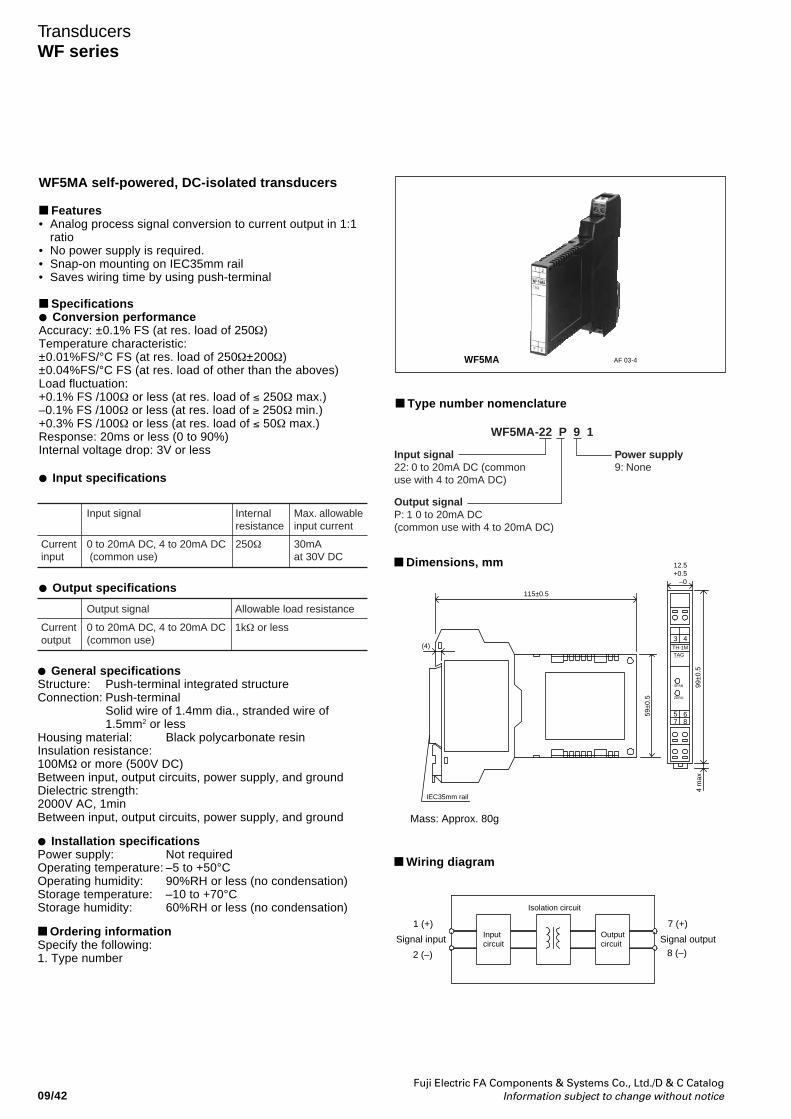
Fuji Electric FA Components & Systems Co., Ltd./D & C CatalogInformation subject to change without notice09/42
TransducersWF series
WF5MA self-powered, DC-isolated transducers
Features• Analog process signal conversion to current output in 1:1
ratio• No power supply is required.• Snap-on mounting on IEC35mm rail• Saves wiring time by using push-terminal
Specifications Conversion performanceAccuracy: ±0.1% FS (at res. load of 250Ω)Temperature characteristic:±0.01%FS/°C FS (at res. load of 250Ω±200Ω)±0.04%FS/°C FS (at res. load of other than the aboves)Load fluctuation:+0.1% FS /100Ω or less (at res. load of ≤ 250Ω max.)–0.1% FS /100Ω or less (at res. load of ≥ 250Ω min.)+0.3% FS /100Ω or less (at res. load of ≤ 50Ω max.)Response: 20ms or less (0 to 90%)Internal voltage drop: 3V or less
Input specifications
Output specifications
General specificationsStructure: Push-terminal integrated structureConnection: Push-terminal
Solid wire of 1.4mm dia., stranded wire of1.5mm2 or less
Housing material: Black polycarbonate resinInsulation resistance:100MΩ or more (500V DC)Between input, output circuits, power supply, and groundDielectric strength:2000V AC, 1minBetween input, output circuits, power supply, and ground
Installation specificationsPower supply: Not requiredOperating temperature: –5 to +50°COperating humidity: 90%RH or less (no condensation)Storage temperature: –10 to +70°CStorage humidity: 60%RH or less (no condensation)
Ordering informationSpecify the following:1. Type number
Type number nomenclature
Dimensions, mm
Wiring diagram
WF5MA AF 03-4
99±0
.5
43
6587
SPAN
ZERO
TAGTH-1M
4 m
ax
12.5+0.5
–0
59±0
.5
115±0.5
(4)
IEC35mm rail
Mass: Approx. 80g
Input signal Internal resistance
Max. allowable input current
0 to 20mA DC, 4 to 20mA DC (common use)
Current input
250Ω 30mA at 30V DC
Output signal Allowable load resistance
0 to 20mA DC, 4 to 20mA DC (common use)
Current output
1kΩ or less
Input signal22: 0 to 20mA DC (common use with 4 to 20mA DC)
Output signalP: 1 0 to 20mA DC (common use with 4 to 20mA DC)
Power supply9: None
WF5MA-22 P 9 1
Signal outputSignal input
Isolation circuit
Inputcircuit
1 (+)
2 (–) 8 (–)
7 (+)Outputcircuit
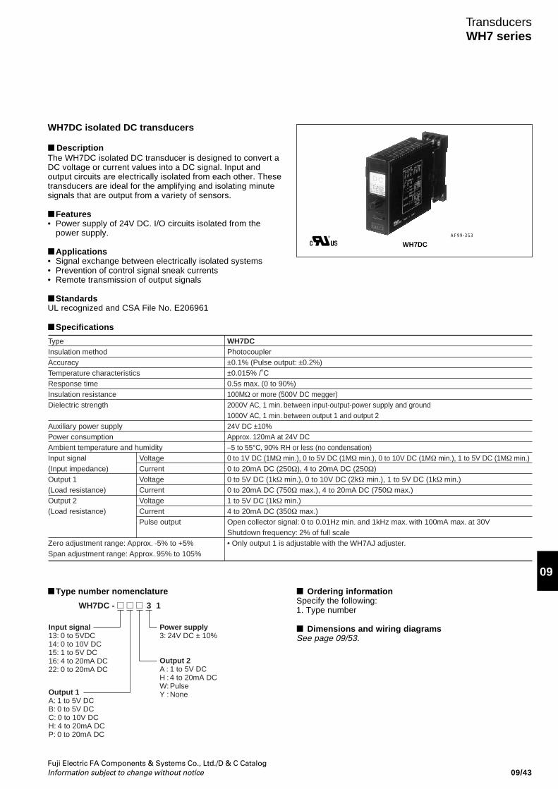
Fuji Electric FA Components & Systems Co., Ltd./D & C CatalogInformation subject to change without notice 09/43
09
TransducersWH7 series
WH7DC isolated DC transducers
DescriptionThe WH7DC isolated DC transducer is designed to convert aDC voltage or current values into a DC signal. Input andoutput circuits are electrically isolated from each other. Thesetransducers are ideal for the amplifying and isolating minutesignals that are output from a variety of sensors.
Features• Power supply of 24V DC. I/O circuits isolated from the
power supply.
Applications• Signal exchange between electrically isolated systems• Prevention of control signal sneak currents• Remote transmission of output signals
StandardsUL recognized and CSA File No. E206961
AF99-353
Type number nomenclature
WH7DC - 13
Input signal13: 0 to 5VDC14: 0 to 10V DC15: 1 to 5V DC16: 4 to 20mA DC22: 0 to 20mA DC
Output 2A : 1 to 5V DCH : 4 to 20mA DCW: PulseY : None
Power supply3: 24V DC ± 10%
Output 1A: 1 to 5V DCB: 0 to 5V DCC: 0 to 10V DCH: 4 to 20mA DCP: 0 to 20mA DC
TypeInsulation methodAccuracyTemperature characteristicsResponse timeInsulation resistanceDielectric strength
Auxiliary power supplyPower consumption Ambient temperature and humidityInput signal(Input impedance)Output 1(Load resistance)Output 2(Load resistance)
Zero adjustment range: Approx. -5% to +5%Span adjustment range: Approx. 95% to 105%
Voltage CurrentVoltageCurrentVoltageCurrentPulse output
WH7DCPhotocoupler±0.1% (Pulse output: ±0.2%)±0.015% /˚C0.5s max. (0 to 90%)100MΩ or more (500V DC megger)2000V AC, 1 min. between input-output-power supply and ground1000V AC, 1 min. between output 1 and output 224V DC ±10%Approx. 120mA at 24V DC–5 to 55°C, 90% RH or less (no condensation)0 to 1V DC (1MΩ min.), 0 to 5V DC (1MΩ min.), 0 to 10V DC (1MΩ min.), 1 to 5V DC (1MΩ min.)0 to 20mA DC (250Ω), 4 to 20mA DC (250Ω)0 to 5V DC (1kΩ min.), 0 to 10V DC (2kΩ min.), 1 to 5V DC (1kΩ min.)0 to 20mA DC (750Ω max.), 4 to 20mA DC (750Ω max.)1 to 5V DC (1kΩ min.)4 to 20mA DC (350Ω max.)Open collector signal: 0 to 0.01Hz min. and 1kHz max. with 100mA max. at 30VShutdown frequency: 2% of full scale• Only output 1 is adjustable with the WH7AJ adjuster.
Specifications
WH7DC
Ordering informationSpecify the following:1. Type number
Dimensions and wiring diagramsSee page 09/53.
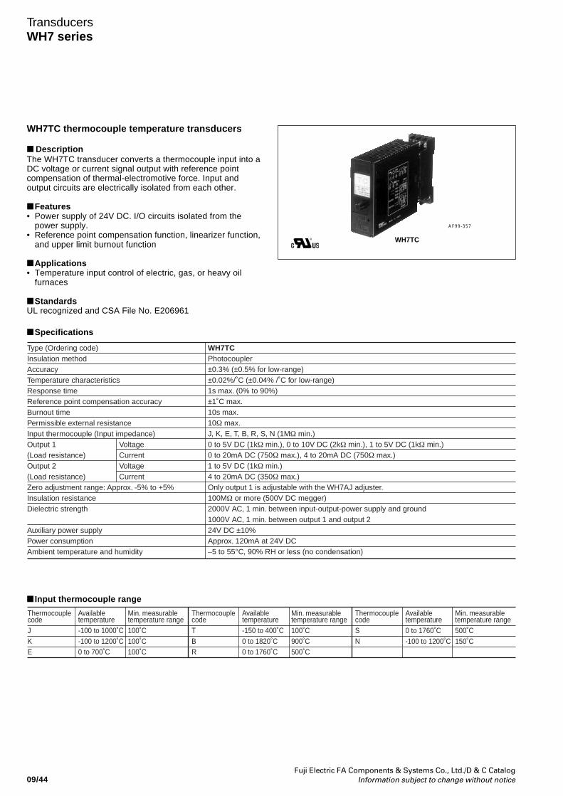
Fuji Electric FA Components & Systems Co., Ltd./D & C CatalogInformation subject to change without notice09/44
TransducersWH7 series
WH7TC thermocouple temperature transducers
DescriptionThe WH7TC transducer converts a thermocouple input into aDC voltage or current signal output with reference pointcompensation of thermal-electromotive force. Input andoutput circuits are electrically isolated from each other.
Features• Power supply of 24V DC. I/O circuits isolated from the
power supply.• Reference point compensation function, linearizer function,
and upper limit burnout function
Applications• Temperature input control of electric, gas, or heavy oil
furnaces
StandardsUL recognized and CSA File No. E206961
Type (Ordering code)Insulation methodAccuracyTemperature characteristicsResponse timeReference point compensation accuracyBurnout timePermissible external resistanceInput thermocouple (Input impedance)Output 1(Load resistance)Output 2(Load resistance)Zero adjustment range: Approx. -5% to +5%Insulation resistanceDielectric strength
Auxiliary power supplyPower consumption Ambient temperature and humidity
VoltageCurrentVoltageCurrent
WH7TCPhotocoupler±0.3% (±0.5% for low-range)±0.02%/˚C (±0.04% /˚C for low-range)1s max. (0% to 90%)±1˚C max.10s max.10Ω max.J, K, E, T, B, R, S, N (1MΩ min.)0 to 5V DC (1kΩ min.), 0 to 10V DC (2kΩ min.), 1 to 5V DC (1kΩ min.)0 to 20mA DC (750Ω max.), 4 to 20mA DC (750Ω max.)1 to 5V DC (1kΩ min.)4 to 20mA DC (350Ω max.)Only output 1 is adjustable with the WH7AJ adjuster.100MΩ or more (500V DC megger)2000V AC, 1 min. between input-output-power supply and ground1000V AC, 1 min. between output 1 and output 224V DC ±10%Approx. 120mA at 24V DC–5 to 55°C, 90% RH or less (no condensation)
AF99-357
Input thermocouple range
ThermocouplecodeJKE
Min. measurabletemperature range500˚C150˚C
Availabletemperature0 to 1760˚C-100 to 1200˚C
ThermocouplecodeSN
Min. measurabletemperature range100˚C900˚C500˚C
ThermocouplecodeTBR
Min. measurabletemperature range100˚C100˚C100˚C
Availabletemperature-100 to 1000˚C-100 to 1200˚C0 to 700˚C
Availabletemperature-150 to 400˚C0 to 1820˚C0 to 1760˚C
WH7TC
Specifications
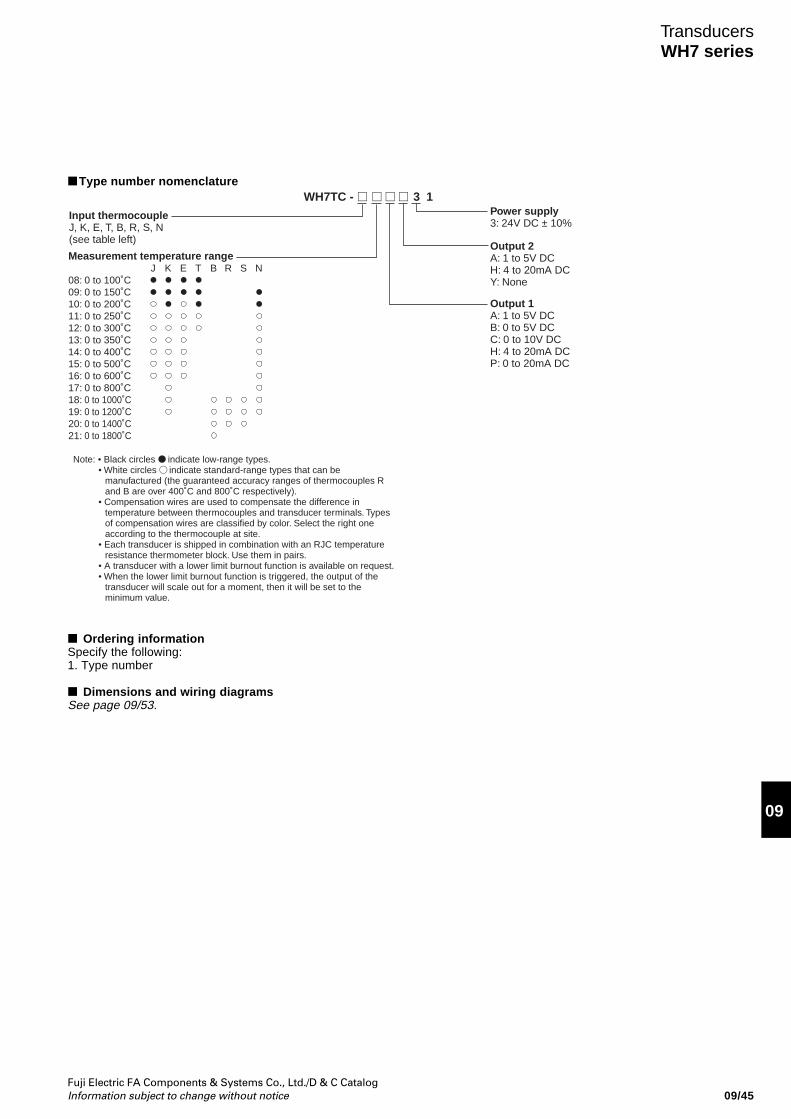
Fuji Electric FA Components & Systems Co., Ltd./D & C CatalogInformation subject to change without notice 09/45
09
TransducersWH7 series
Type number nomenclatureWH7TC - 13
Measurement temperature rangeJ K E T B R S N
08: 0 to 100˚C09: 0 to 150˚C10: 0 to 200˚C11: 0 to 250˚C12: 0 to 300˚C13: 0 to 350˚C14: 0 to 400˚C15: 0 to 500˚C16: 0 to 600˚C17: 0 to 800˚C18: 0 to 1000˚C19: 0 to 1200˚C20: 0 to 1400˚C21: 0 to 1800˚C
Input thermocoupleJ, K, E, T, B, R, S, N(see table left)
Note: • Black circles indicate low-range types.• White circles indicate standard-range types that can be
manufactured (the guaranteed accuracy ranges of thermocouples R and B are over 400˚C and 800˚C respectively).
• Compensation wires are used to compensate the difference in temperature between thermocouples and transducer terminals. Types of compensation wires are classified by color. Select the right one according to the thermocouple at site.
• Each transducer is shipped in combination with an RJC temperature resistance thermometer block. Use them in pairs.
• A transducer with a lower limit burnout function is available on request.• When the lower limit burnout function is triggered, the output of the
transducer will scale out for a moment, then it will be set to the minimum value.
Output 1A: 1 to 5V DCB: 0 to 5V DCC: 0 to 10V DCH: 4 to 20mA DCP: 0 to 20mA DC
Power supply3: 24V DC ± 10%
Output 2A: 1 to 5V DCH: 4 to 20mA DCY: None
Ordering informationSpecify the following:1. Type number
Dimensions and wiring diagramsSee page 09/53.
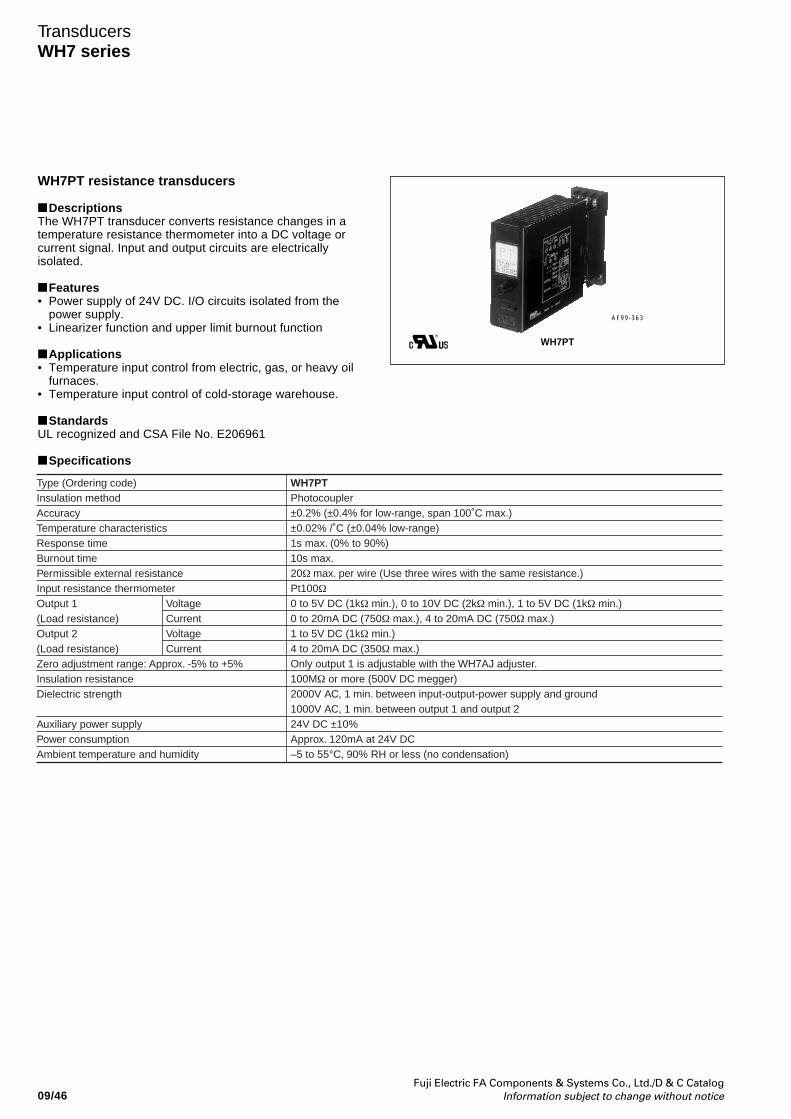
Fuji Electric FA Components & Systems Co., Ltd./D & C CatalogInformation subject to change without notice09/46
TransducersWH7 series
WH7PT resistance transducers
DescriptionsThe WH7PT transducer converts resistance changes in atemperature resistance thermometer into a DC voltage orcurrent signal. Input and output circuits are electricallyisolated.
Features• Power supply of 24V DC. I/O circuits isolated from the
power supply.• Linearizer function and upper limit burnout function
Applications• Temperature input control from electric, gas, or heavy oil
furnaces.• Temperature input control of cold-storage warehouse.
StandardsUL recognized and CSA File No. E206961
Specifications
Type (Ordering code)Insulation methodAccuracyTemperature characteristicsResponse timeBurnout timePermissible external resistanceInput resistance thermometerOutput 1(Load resistance)Output 2(Load resistance)Zero adjustment range: Approx. -5% to +5%Insulation resistanceDielectric strength
Auxiliary power supplyPower consumption Ambient temperature and humidity
VoltageCurrentVoltageCurrent
WH7PTPhotocoupler±0.2% (±0.4% for low-range, span 100˚C max.)±0.02% /˚C (±0.04% low-range)1s max. (0% to 90%)10s max.20Ω max. per wire (Use three wires with the same resistance.)Pt100Ω0 to 5V DC (1kΩ min.), 0 to 10V DC (2kΩ min.), 1 to 5V DC (1kΩ min.)0 to 20mA DC (750Ω max.), 4 to 20mA DC (750Ω max.)1 to 5V DC (1kΩ min.)4 to 20mA DC (350Ω max.)Only output 1 is adjustable with the WH7AJ adjuster.100MΩ or more (500V DC megger)2000V AC, 1 min. between input-output-power supply and ground1000V AC, 1 min. between output 1 and output 224V DC ±10%Approx. 120mA at 24V DC–5 to 55°C, 90% RH or less (no condensation)
AF99-363
WH7PT
Fuji Electric FA Components & Systems Co., Ltd./D & C CatalogInformation subject to change without notice 09/47
09
TransducersWH7 series
Type number nomenclature
WH7PT - 132
Measurement temperature range10: 0 to 50˚C/For low-range11: 0 to 100˚C/For low-range12: 0 to 150˚C13: 0 to 200˚C14: 0 to 250˚C15: 0 to 300˚C16: 0 to 350˚C17: 0 to 400˚C18: 0 to 500˚C19: 0 to 600˚C20: -20 to +80˚C/For low-range21: -40 to +60˚C/For low-range22: -50 to +50˚C/For low-range23: -50 to +100˚C24: -50 to +150˚C25: -100 to +100˚C
Input temperature resistance thermometer2: Pt100Ω
Output 2A: 1 to 5V DCH: 4 to 20mA DCY: None
Output 1A: 1 to 5V DCB: 0 to 5V DCC: 0 to 10V DCH: 4 to 20mA DCP: 0 to 20mA DC
Power supply3: 24V DC ± 10%
Note: When the lower limit burnout function is triggered, the output of the transducer will scale out for a moment, then it will be set to the minimum value.
Ordering informationSpecify the following:1. Type number
Dimensions and wiring diagramsSee page 09/53.
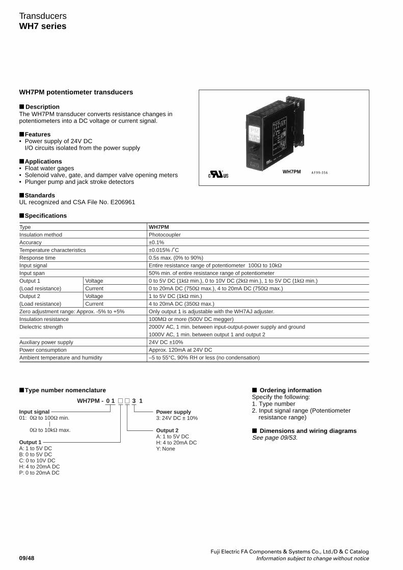
Fuji Electric FA Components & Systems Co., Ltd./D & C CatalogInformation subject to change without notice09/48
TransducersWH7 series
Type number nomenclature
Output 2A: 1 to 5V DCH: 4 to 20mA DCY: None
Power supply3: 24V DC ± 10%
WH7PM - 1310
Input signal01: 0Ω to 100Ω min.
0Ω to 10kΩ max.
Output 1A: 1 to 5V DCB: 0 to 5V DCC: 0 to 10V DCH: 4 to 20mA DCP: 0 to 20mA DC
Ordering informationSpecify the following:1. Type number2. Input signal range (Potentiometer
resistance range)
Dimensions and wiring diagramsSee page 09/53.
WH7PM potentiometer transducers
DescriptionThe WH7PM transducer converts resistance changes inpotentiometers into a DC voltage or current signal.
Features• Power supply of 24V DC
I/O circuits isolated from the power supply
Applications• Float water gages• Solenoid valve, gate, and damper valve opening meters• Plunger pump and jack stroke detectors
StandardsUL recognized and CSA File No. E206961
Specifications
TypeInsulation methodAccuracyTemperature characteristicsResponse timeInput signalInput spanOutput 1(Load resistance)Output 2(Load resistance)Zero adjustment range: Approx. -5% to +5%Insulation resistanceDielectric strength
Auxiliary power supplyPower consumption Ambient temperature and humidity
VoltageCurrentVoltageCurrent
WH7PMPhotocoupler±0.1%±0.015% /˚C0.5s max. (0% to 90%)Entire resistance range of potentiometer 100Ω to 10kΩ50% min. of entire resistance range of potentiometer0 to 5V DC (1kΩ min.), 0 to 10V DC (2kΩ min.), 1 to 5V DC (1kΩ min.)0 to 20mA DC (750Ω max.), 4 to 20mA DC (750Ω max.)1 to 5V DC (1kΩ min.)4 to 20mA DC (350Ω max.)Only output 1 is adjustable with the WH7AJ adjuster.100MΩ or more (500V DC megger)2000V AC, 1 min. between input-output-power supply and ground1000V AC, 1 min. between output 1 and output 224V DC ±10%Approx. 120mA at 24V DC–5 to 55°C, 90% RH or less (no condensation)
WH7PM AF99-356
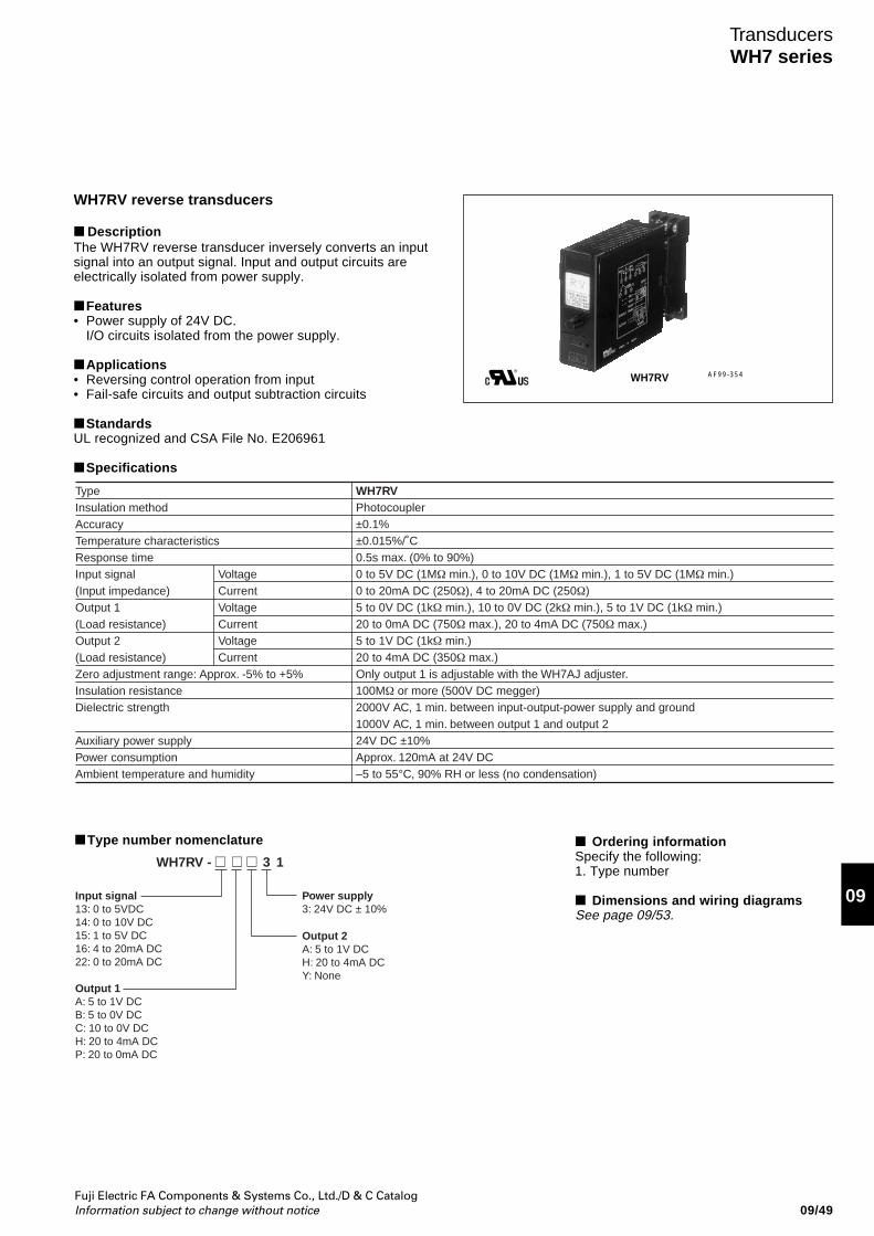
Fuji Electric FA Components & Systems Co., Ltd./D & C CatalogInformation subject to change without notice 09/49
09
TransducersWH7 series
WH7RV reverse transducers
DescriptionThe WH7RV reverse transducer inversely converts an inputsignal into an output signal. Input and output circuits areelectrically isolated from power supply.
Features• Power supply of 24V DC.
I/O circuits isolated from the power supply.
Applications• Reversing control operation from input• Fail-safe circuits and output subtraction circuits
StandardsUL recognized and CSA File No. E206961
Specifications
TypeInsulation methodAccuracyTemperature characteristicsResponse timeInput signal(Input impedance)Output 1(Load resistance)Output 2(Load resistance)Zero adjustment range: Approx. -5% to +5%Insulation resistanceDielectric strength
Auxiliary power supplyPower consumption Ambient temperature and humidity
VoltageCurrentVoltageCurrentVoltageCurrent
WH7RVPhotocoupler±0.1%±0.015%/˚C0.5s max. (0% to 90%)0 to 5V DC (1MΩ min.), 0 to 10V DC (1MΩ min.), 1 to 5V DC (1MΩ min.)0 to 20mA DC (250Ω), 4 to 20mA DC (250Ω)5 to 0V DC (1kΩ min.), 10 to 0V DC (2kΩ min.), 5 to 1V DC (1kΩ min.)20 to 0mA DC (750Ω max.), 20 to 4mA DC (750Ω max.)5 to 1V DC (1kΩ min.)20 to 4mA DC (350Ω max.)Only output 1 is adjustable with the WH7AJ adjuster.100MΩ or more (500V DC megger)2000V AC, 1 min. between input-output-power supply and ground1000V AC, 1 min. between output 1 and output 224V DC ±10%Approx. 120mA at 24V DC–5 to 55°C, 90% RH or less (no condensation)
AF99-354WH7RV
Type number nomenclature
Output 2A: 5 to 1V DCH: 20 to 4mA DCY: None
Power supply3: 24V DC ± 10%
Input signal13: 0 to 5VDC14: 0 to 10V DC15: 1 to 5V DC16: 4 to 20mA DC22: 0 to 20mA DC
Output 1A: 5 to 1V DCB: 5 to 0V DCC: 10 to 0V DCH: 20 to 4mA DCP: 20 to 0mA DC
WH7RV - 13
Ordering informationSpecify the following:1. Type number
Dimensions and wiring diagramsSee page 09/53.
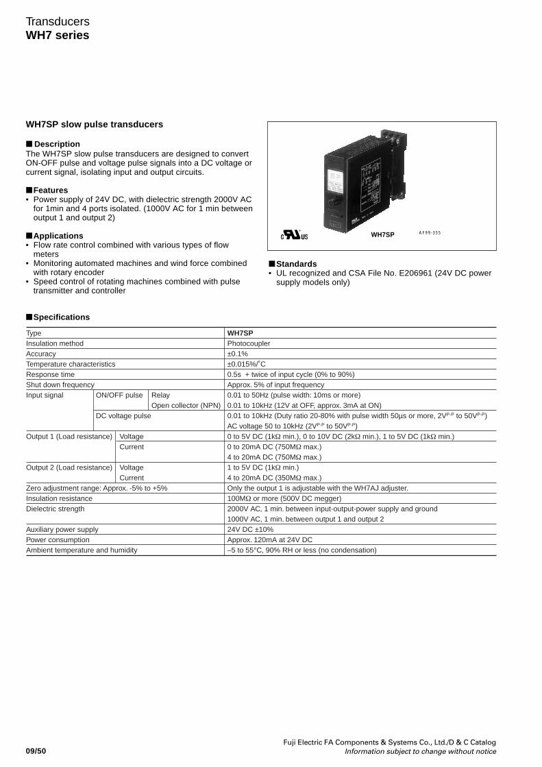
Fuji Electric FA Components & Systems Co., Ltd./D & C CatalogInformation subject to change without notice09/50
TransducersWH7 series
WH7SP slow pulse transducers
DescriptionThe WH7SP slow pulse transducers are designed to convertON-OFF pulse and voltage pulse signals into a DC voltage orcurrent signal, isolating input and output circuits.
Features• Power supply of 24V DC, with dielectric strength 2000V AC
for 1min and 4 ports isolated. (1000V AC for 1 min betweenoutput 1 and output 2)
Applications• Flow rate control combined with various types of flow
meters• Monitoring automated machines and wind force combined
with rotary encoder• Speed control of rotating machines combined with pulse
transmitter and controller
AF99-355WH7SP
TypeInsulation methodAccuracyTemperature characteristicsResponse timeShut down frequencyInput signal
Output 1 (Load resistance)
Output 2 (Load resistance)
Zero adjustment range: Approx. -5% to +5%Insulation resistanceDielectric strength
Auxiliary power supplyPower consumption Ambient temperature and humidity
ON/OFF pulse
DC voltage pulse
VoltageCurrent
VoltageCurrent
RelayOpen collector (NPN)
WH7SPPhotocoupler±0.1%±0.015%/˚C0.5s + twice of input cycle (0% to 90%)Approx. 5% of input frequency0.01 to 50Hz (pulse width: 10ms or more)0.01 to 10kHz (12V at OFF, approx. 3mA at ON)0.01 to 10kHz (Duty ratio 20-80% with pulse width 50µs or more, 2VP-P to 50VP-P) AC voltage 50 to 10kHz (2VP-P to 50VP-P)0 to 5V DC (1kΩ min.), 0 to 10V DC (2kΩ min.), 1 to 5V DC (1kΩ min.)0 to 20mA DC (750MΩ max.)4 to 20mA DC (750MΩ max.)1 to 5V DC (1kΩ min.)4 to 20mA DC (350MΩ max.)Only the output 1 is adjustable with the WH7AJ adjuster.100MΩ or more (500V DC megger)2000V AC, 1 min. between input-output-power supply and ground1000V AC, 1 min. between output 1 and output 224V DC ±10%Approx. 120mA at 24V DC–5 to 55°C, 90% RH or less (no condensation)
Standards• UL recognized and CSA File No. E206961 (24V DC power
supply models only)
Specifications
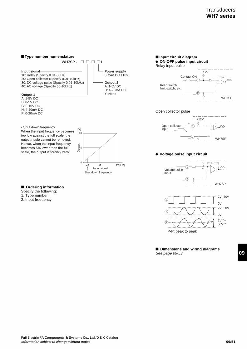
Fuji Electric FA Components & Systems Co., Ltd./D & C CatalogInformation subject to change without notice 09/51
09
TransducersWH7 series
Type number nomenclature
• Shut down frequencyWhen the input frequency becomestoo low against the full scale. theoutput ripple cannot be removed.Hence, when the input frequencybecomes 5% lower than the fullscale, the output is forcibly zero.
10
5
02.5 25 50
[V]
[Hz]
Out
put
Input signalShut down frequency
Power supply3: 24V DC ±10%
Output 2A: 1-5V DCH: 4-20mA DCY: None
Input signal10: Relay (Specify 0.01-50Hz)20: Open collector (Specify 0.01-10kHz)30: DC voltage pulse (Specify 0.01-10kHz)40: AC voltage (Specify 50-10kHz)
Output 1A: 1-5V DCB: 0-5V DCC: 0-10V DCH: 4-20mA DCP: 0-20mA DC
WH7SP - 1
Ordering informationSpecify the following:1. Type number2. Input frequency
Input circuit diagram ON-OFF pulse input circuitRelay input pulse
Open collector pulse
Voltage pulse input circuit
Dimensions and wiring diagramsSee page 09/53.
1
2
+12VContact ON
Reed switch,limit switch, etc.
WH7SP
Open collector input
++12V
1
2WH7SP
1
1
2
3
2
Voltage pulse input
P-P: peak to peak
WH7SP
2VPP–50VPP
2V–50V
0V2V–50V
0V
OV
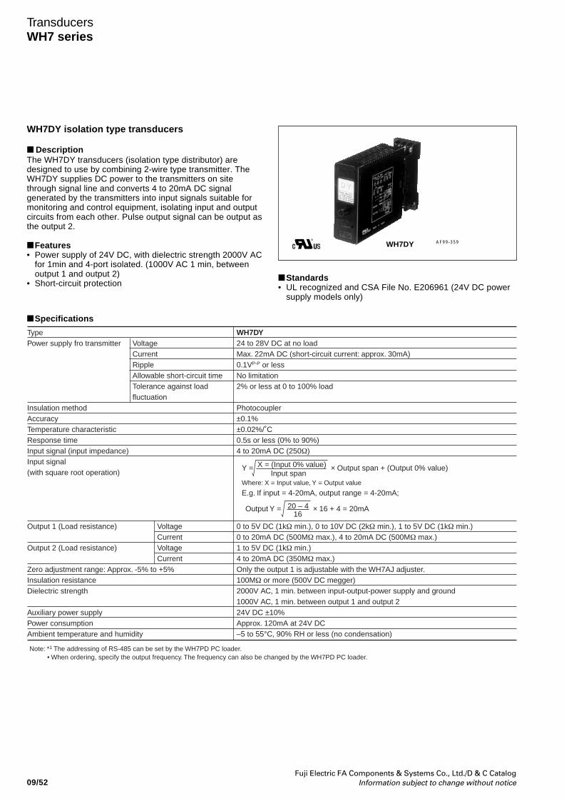
Fuji Electric FA Components & Systems Co., Ltd./D & C CatalogInformation subject to change without notice09/52
TransducersWH7 series
WH7DY isolation type transducers
DescriptionThe WH7DY transducers (isolation type distributor) aredesigned to use by combining 2-wire type transmitter. TheWH7DY supplies DC power to the transmitters on sitethrough signal line and converts 4 to 20mA DC signalgenerated by the transmitters into input signals suitable formonitoring and control equipment, isolating input and outputcircuits from each other. Pulse output signal can be output asthe output 2.
Features• Power supply of 24V DC, with dielectric strength 2000V AC
for 1min and 4-port isolated. (1000V AC 1 min, betweenoutput 1 and output 2)
• Short-circuit protection
AF99-359WH7DY
• When ordering, specify the output frequency. The frequency can also be changed by the WH7PD PC loader.Note: *1 The addressing of RS-485 can be set by the WH7PD PC loader.
TypePower supply fro transmitter
Insulation methodAccuracyTemperature characteristicResponse timeInput signal (input impedance)Input signal (with square root operation)
Output 1 (Load resistance)
Output 2 (Load resistance)
Zero adjustment range: Approx. -5% to +5%Insulation resistanceDielectric strength
Auxiliary power supplyPower consumption Ambient temperature and humidity
VoltageCurrentRippleAllowable short-circuit timeTolerance against loadfluctuation
VoltageCurrentVoltageCurrent
WH7DY24 to 28V DC at no loadMax. 22mA DC (short-circuit current: approx. 30mA)0.1VP-P or lessNo limitation2% or less at 0 to 100% load
Photocoupler±0.1%±0.02%/˚C0.5s or less (0% to 90%)4 to 20mA DC (250Ω)
0 to 5V DC (1kΩ min.), 0 to 10V DC (2kΩ min.), 1 to 5V DC (1kΩ min.)0 to 20mA DC (500MΩ max.), 4 to 20mA DC (500MΩ max.)1 to 5V DC (1kΩ min.)4 to 20mA DC (350MΩ max.)Only the output 1 is adjustable with the WH7AJ adjuster.100MΩ or more (500V DC megger)2000V AC, 1 min. between input-output-power supply and ground1000V AC, 1 min. between output 1 and output 224V DC ±10%Approx. 120mA at 24V DC–5 to 55°C, 90% RH or less (no condensation)
Where: X = Input value, Y = Output value
E.g. If input = 4-20mA, output range = 4-20mA;
Y = × Output span + (Output 0% value)X = (Input 0% value)Input span
Output Y = × 16 + 4 = 20mA20 – 416
Standards• UL recognized and CSA File No. E206961 (24V DC power
supply models only)
Specifications
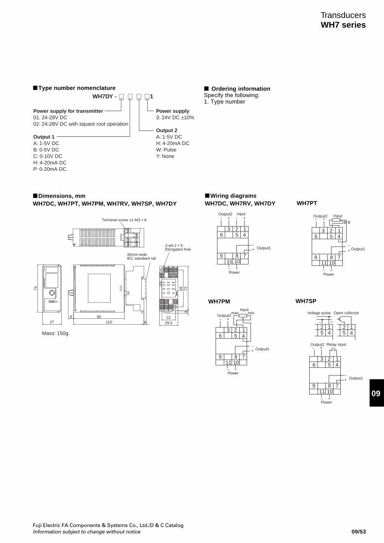
Fuji Electric FA Components & Systems Co., Ltd./D & C CatalogInformation subject to change without notice 09/53
09
TransducersWH7 series
Type number nomenclature Ordering informationSpecify the following:1. Type number
Power supply3: 24V DC ±10%
Output 2A: 1-5V DCH: 4-20mA DCW: PulseY: None
Power supply for transmitter01: 24-28V DC02: 24-28V DC with square root operation
Output 1A: 1-5V DCB: 0-5V DCC: 0-10V DCH: 4-20mA DCP: 0-20mA DC
WH7DY - 1
Terminal screw 11-M3 × 8
2-ø4.2 × 5 Elongated hole
35mm-wideIEC standard rail
74
8 8011027 4
47259
2229.5
Mass: 150g
Dimensions, mmWH7DC, WH7PT, WH7PM, WH7RV, WH7SP, WH7DY WH7PT
WH7PM
Wiring diagramsWH7DC, WH7RV, WH7DY
3 2 16 5 4
9 8 711 10
Output1
Output2 Input
Power
– +– +
+–
– +
WH7SP
Output1
3 2 16 5 4
9 8 711 10
Inputmax min
Power
+–
– +
Output2– +
Output2
Output1
3 2 1
2 15 4
2 15 4
6 5 4
9 8 711 10
Power
+–
– +
– +Relay input
Open collectorVoltage pulse
– +
B B
Output1
3 2 16 5 4
9 8 711 10
Input
Power
+–
– +
Output2– +
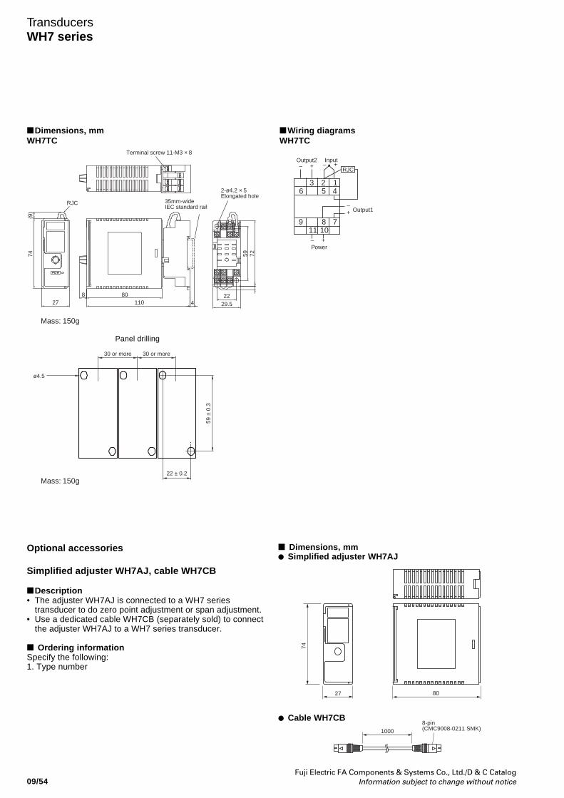
Fuji Electric FA Components & Systems Co., Ltd./D & C CatalogInformation subject to change without notice09/54
TransducersWH7 series
Dimensions, mm Simplified adjuster WH7AJ
Cable WH7CB
Optional accessories
Simplified adjuster WH7AJ, cable WH7CB
Description• The adjuster WH7AJ is connected to a WH7 series
transducer to do zero point adjustment or span adjustment.• Use a dedicated cable WH7CB (separately sold) to connect
the adjuster WH7AJ to a WH7 series transducer.
Ordering informationSpecify the following:1. Type number
8027
74
10008-pin(CMC9008-0211 SMK)
35mm-wideIEC standard rail
RJC
Terminal screw 11-M3 × 8
2-ø4.2 × 5 Elongated hole
ø4.5
74(9
)
8 8011027 4
7259
2229.5
30 or more 30 or more
59 ±
0.3
22 ± 0.2
Mass: 150g
Mass: 150g
Panel drilling
Output1
3 2 16 5 4
9 8 711 10
Input
Power
– +
+–
– +
RJC
Output2– +
Dimensions, mmWH7TC
Wiring diagramsWH7TC
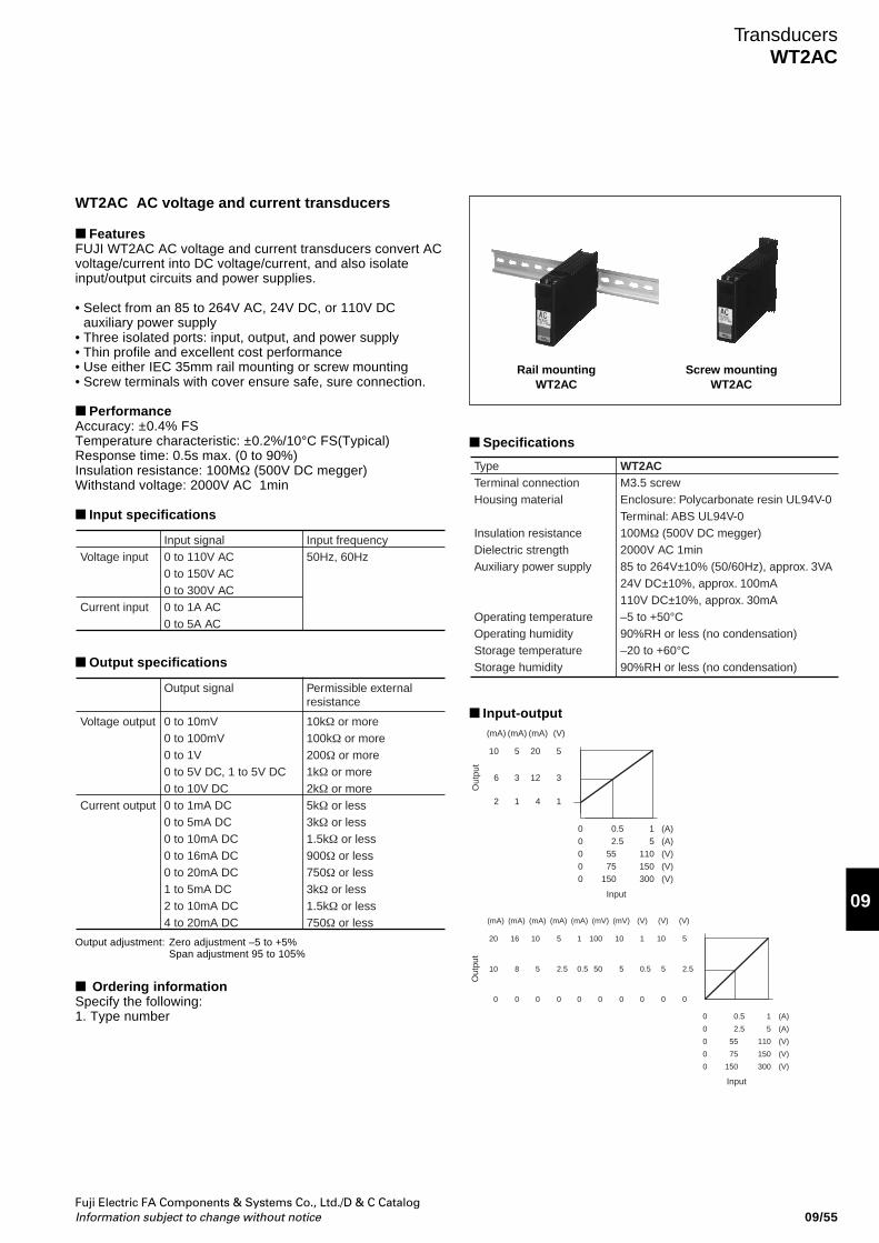
Fuji Electric FA Components & Systems Co., Ltd./D & C CatalogInformation subject to change without notice 09/55
09
TransducersWT2AC
Rail mountingWT2AC
Screw mountingWT2AC
WT2AC AC voltage and current transducers
FeaturesFUJI WT2AC AC voltage and current transducers convert ACvoltage/current into DC voltage/current, and also isolateinput/output circuits and power supplies.
• Select from an 85 to 264V AC, 24V DC, or 110V DCauxiliary power supply
• Three isolated ports: input, output, and power supply• Thin profile and excellent cost performance• Use either IEC 35mm rail mounting or screw mounting• Screw terminals with cover ensure safe, sure connection.
PerformanceAccuracy: ±0.4% FSTemperature characteristic: ±0.2%/10°C FS(Typical)Response time: 0.5s max. (0 to 90%)Insulation resistance: 100MΩ (500V DC megger)Withstand voltage: 2000V AC 1min
Input specifications
Output specifications
Input signal0 to 110V AC0 to 150V AC0 to 300V AC0 to 1A AC0 to 5A AC
Input frequency50Hz, 60HzVoltage input
Current input
Output signal
0 to 10mV0 to 100mV0 to 1V0 to 5V DC, 1 to 5V DC0 to 10V DC0 to 1mA DC0 to 5mA DC0 to 10mA DC0 to 16mA DC0 to 20mA DC1 to 5mA DC2 to 10mA DC4 to 20mA DC
Permissible externalresistance
10kΩ or more100kΩ or more200Ω or more1kΩ or more2kΩ or more5kΩ or less3kΩ or less1.5kΩ or less900Ω or less750Ω or less3kΩ or less1.5kΩ or less750Ω or less
Voltage output
Current output
Output adjustment: Zero adjustment –5 to +5%Span adjustment 95 to 105%
Ordering informationSpecify the following:1. Type number
Specifications
WT2ACM3.5 screwEnclosure: Polycarbonate resin UL94V-0Terminal: ABS UL94V-0100MΩ (500V DC megger)2000V AC 1min85 to 264V±10% (50/60Hz), approx. 3VA24V DC±10%, approx. 100mA110V DC±10%, approx. 30mA–5 to +50°C90%RH or less (no condensation)–20 to +60°C90%RH or less (no condensation)
TypeTerminal connectionHousing material
Insulation resistanceDielectric strengthAuxiliary power supply
Operating temperatureOperating humidityStorage temperatureStorage humidity
Input-output(mA) (mA) (mA) (V)
5
3
1
20
12
4
5
3
1
10
6
2
00000
0.52.5
5575
150
15
110150300
(A)(A)(V)(V)(V)
Input
Out
put
(mA) (mA) (mA) (mA) (mA) (mV) (mV) (V) (V)(V)
20
10
0
16
8
0
10
5
0
5
2.5
0
1
0.5
0
100
50
0
10
5
0
1
0.5
0
5
2.5
0
10
5
0
Input
(A)
(A)
(V)
(V)
(V)
0
0
0
0
0
0.5
2.5
55
75
150
1
5
110
150
300
Out
put
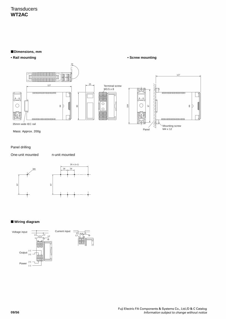
Fuji Electric FA Components & Systems Co., Ltd./D & C CatalogInformation subject to change without notice09/56
TransducersWT2AC
Dimensions, mm
• Screw mounting
Panel drilling
One-unit mounted n-unit mounted
Wiring diagram
• Rail mounting
35mm wide IEC rail
127
Mounting screwM4 x 12Panel
104
97
127
Terminal screwM3.5 x 8
80
25
M4 26 26
26 x (n-1)
97 97
1
3
2
4
Current input
CTLK
k R
1
3
2
4
5
7
6
8
U V
u vVT
Voltage input
Output
Power
(–)
(+)
(–)
(+)
Mass: Approx. 200g
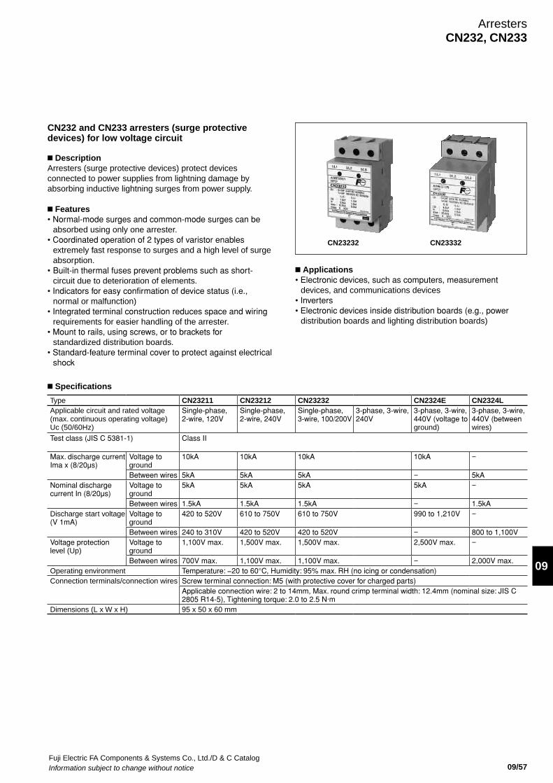
Fuji Electric FA Components & Systems Co., Ltd./D & C CatalogInformation subject to change without notice 09/57
09
ArrestersCN232, CN233
CN232 and CN233 arresters (surge protective devices) for low voltage circuit
n DescriptionArresters (surge protective devices) protect devices connected to power supplies from lightning damage by absorbing inductive lightning surges from power supply.
n Features• Normal-mode surges and common-mode surges can be
absorbed using only one arrester.• Coordinated operation of 2 types of varistor enables
extremely fast response to surges and a high level of surge absorption.
• Built-in thermal fuses prevent problems such as short- circuit due to deterioration of elements.
• Indicators for easy confirmation of device status (i.e., normal or malfunction)
• Integrated terminal construction reduces space and wiring requirements for easier handling of the arrester.
• Mount to rails, using screws, or to brackets for standardized distribution boards.
• Standard-feature terminal cover to protect against electrical shock
CN23232 CN23332
n Applications• Electronic devices, such as computers, measurement
devices, and communications devices • Inverters• Electronic devices inside distribution boards (e.g., power
distribution boards and lighting distribution boards)
n Specifications
Type CN23211 CN23212 CN23232 CN2324E CN2324LApplicable circuit and rated voltage (max. continuous operating voltage) Uc (50/60Hz)
Single-phase, 2-wire, 120V
Single-phase, 2-wire, 240V
Single-phase,3-wire, 100/200V
3-phase, 3-wire, 240V
3-phase, 3-wire, 440V (voltage to ground)
3-phase, 3-wire, 440V (between wires)
Test class (JIS C 5381-1) Class II
Max. discharge current Ima x (8/20µs)
Voltage to ground
10kA 10kA 10kA 10kA −
Between wires 5kA 5kA 5kA − 5kANominal discharge current In (8/20µs)
Voltage to ground
5kA 5kA 5kA 5kA −
Between wires 1.5kA 1.5kA 1.5kA − 1.5kADischarge start voltage (V 1mA)
Voltage to ground
420 to 520V 610 to 750V 610 to 750V 990 to 1,210V −
Between wires 240 to 310V 420 to 520V 420 to 520V − 800 to 1,100VVoltage protection level (Up)
Voltage to ground
1,100V max. 1,500V max. 1,500V max. 2,500V max. −
Between wires 700V max. 1,100V max. 1,100V max. − 2,000V max. Operating environment Temperature: −20 to 60°C, Humidity: 95% max. RH (no icing or condensation)Connection terminals/connection wires Screw terminal connection: M5 (with protective cover for charged parts)
Applicable connection wire: 2 to 14mm, Max. round crimp terminal width: 12.4mm (nominal size: JIS C 2805 R14-5), Tightening torque: 2.0 to 2.5 N·m
Dimensions (L x W x H) 95 x 50 x 60 mm
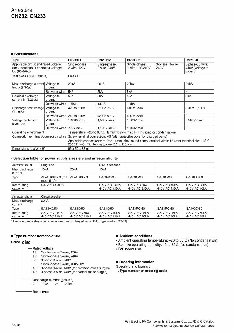
Fuji Electric FA Components & Systems Co., Ltd./D & C Catalog Information subject to change without notice 09/58
ArrestersCN232, CN233
• Selection table for power supply arresters and arrester shunts
Arrester shunt Plug fuse Circuit breaker Max. discharge current
10kA 20kA 10kA
Type AFaC-30X x 3 (rail mounting)*
AFaC-60 x 3 EA33AC/30 SA33C/30 SA53C/30 SA53RC/30
Interrupting capacity
600V AC 100kA 220V AC 2.5kA440V AC 1.5kA
220V AC 5kA440V AC 2.5kA
220V AC 10kA440V AC 7.5kA
220V AC 25kA440V AC 10kA
Arrester shunt Circuit breaker Max. discharge current
20kA
Type EA53AC/50 EA53C/50 SA53C/50 SA53RC/50 SA63RC/60 SA103C/60Interrupting capacity
220V AC 2.5kA440V AC 1.5kA
220V AC 5kA440V AC 2.5kA
220V AC 10kA440V AC 7.5kA
220V AC 25kA440V AC 10kA
220V AC 25kA440V AC 10kA
220V AC 50kA440V AC 25kA
* If required, separately order a protective cover for charged parts (30A). (Type number: CG-30)
n Ambient conditions• Ambient operating temperature: –20 to 50˚C (No condensation)• Relative operating humidity: 45 to 85% (No condensation)• For indoor use
n Ordering informationSpecify the following :1. Type number or ordering code
n Type number nomenclature
Type CN23311 CN23312 CN23332 CN2334EApplicable circuit and rated voltage (max. continuous operating voltage) Uc (50/60Hz)
Single-phase, 2-wire, 120V
Single-phase, 2-wire, 240V
Single-phase, 3-wire, 100/200V
3-phase, 3-wire, 240V
3-phase, 3-wire, 440V (voltage to ground)
Test class (JIS C 5381-1) Class II
Max. discharge current Ima x (8/20µs)
Voltage to ground
20kA 20kA 20kA 20kA
Between wires 5kA 5kA 5kA −Nominal discharge current In (8/20µs)
Voltage to ground
5kA 5kA 5kA 5kA
Between wires 1.5kA 1.5kA 1.5kA −Discharge start voltage (V 1mA)
Voltage to ground
420 to 520V 610 to 750V 610 to 750V 850 to 1,100V
Between wires 240 to 310V 420 to 520V 420 to 520V −Voltage protection level (Up)
Voltage to ground
1,100V max. 1,500V max. 1,500V max. 2,500V max.
Between wires 700V max. 1,100V max. 1,100V max. −Operating environment Temperature: −20 to 60°C, Humidity: 95% max. RH (no icing or condensation)Connection terminals/connection wires Screw terminal connection: M5 (with protective cover for charged parts)
Applicable connection wire: 2 to 14mm, Max. round crimp terminal width: 12.4mm (nominal size: JIS C 2805 R14-5), Tightening torque: 2.0 to 2.5 N·m
Dimensions (L x W x H) 95 x 50 x 83 mm
n Specifications
CN23 2 32
Rated voltage11: Single-phase 2-wire, 120V12: Single-phase 2-wire, 240V32: 3-phase 3-wire, 240V Single-phase 3-wire, 100/200V4E: 3-phase 3-wire, 440V (for common-mode surges)4L: 3-phase 3-wire, 440V (for normal-mode surges)
Discharge current (ground)2: 10kA 3: 20kA
Basic type
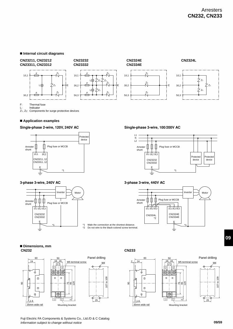
Fuji Electric FA Components & Systems Co., Ltd./D & C CatalogInformation subject to change without notice 09/59
09
n Application examples
n Dimensions, mm
21.6
Mounting bracket
120
9575
16 1650
12.5M5 terminal screw
Panel drilling
107
to 1
09
M4
25
35mm wide rail
90
2460
F: Thermal fuseL: IndicatorZ1, Z2: Components for surge protective devices
n Internal circuit diagrams
CN23211, CN23212CN23311, CN23312
CN23232CN23332
CN2324ECN2334E
CN2324L
3-phase 3-wire, 240V AC
Single-phase 2-wire, 120V, 240V AC
3-phase 3-wire, 440V AC
Single-phase 3-wire, 100/200V AC
CN232
2
Mounting bracket
120
9575
16 1650
12.5M5 terminal screw
Panel drilling
107
to 1
09
M4
25
35mm wide rail
90
24283
1.6
CN233
ArrestersCN232, CN233
1/L1F
F
L Z1 E
Z2
Z2
3/L2
1/L1F
F
FL
L Z1 Z1
Z1
E
Z2
Z2
Z2
5/L3
3/L2
1/L1
Z1
Z1
Z1E
5/L3
3/L2
1/L1Z2
Z2
Z2
5/L3
3/L2
1/L1 3/L2
CN23211, 12CN23311, 12
E
1/L1 3/L2
CN23232CN23332
E
5/L3
L1NL2
1/L1 3/L2
CN23232CN23332
E
5/L3
1/L1 3/L2 5/L3 1/L1 3/L2
CN2324L*2
*1 *1
*1 *1
CN2324ECN2334E
Inverter
Arrestershunt
Arrestershunt
Arrestershunt
Arrestershunt
Plug fuse or MCCB
MotorInverter
Protecteddevice
Protecteddevice
Protecteddevice
Motor
E
5/L3
*1 Male the connection at the shortest distance.*2 Do not wire to the black-colored screw terminal.
Plug fuse or MCCBPlug fuse or MCCB
Plug fuse or MCCB
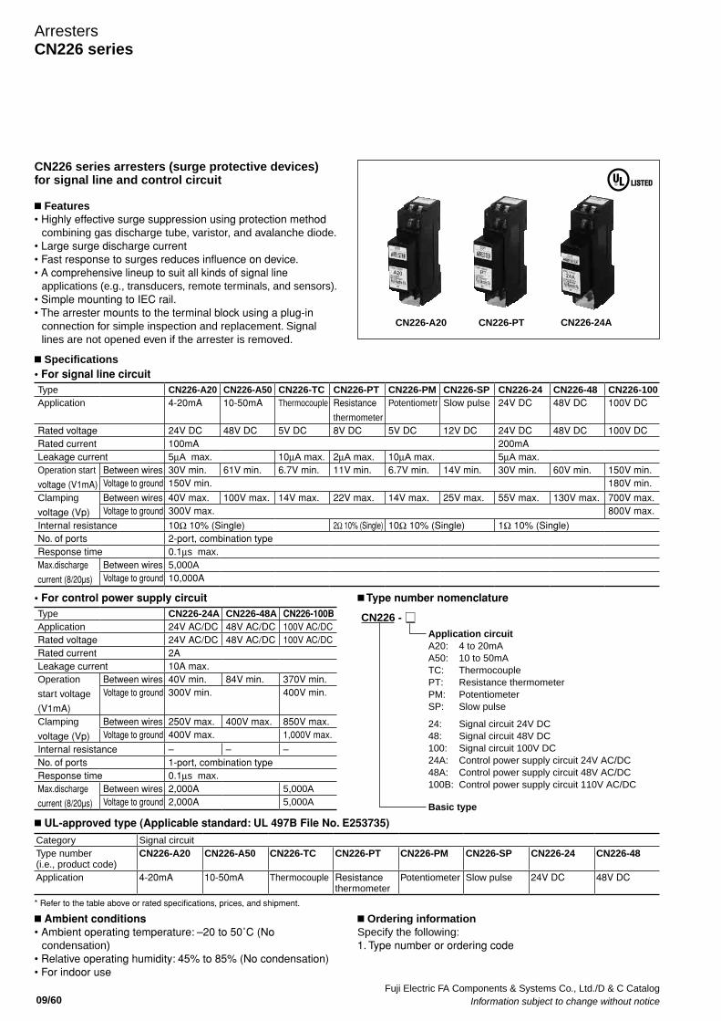
Fuji Electric FA Components & Systems Co., Ltd./D & C Catalog Information subject to change without notice 09/60
ArrestersCN226 series
CN226 series arresters (surge protective devices) for signal line and control circuit
n Features• Highly effective surge suppression using protection method
combining gas discharge tube, varistor, and avalanche diode. • Large surge discharge current• Fast response to surges reduces influence on device.• A comprehensive lineup to suit all kinds of signal line
applications (e.g., transducers, remote terminals, and sensors).• Simple mounting to IEC rail.• The arrester mounts to the terminal block using a plug-in
connection for simple inspection and replacement. Signal lines are not opened even if the arrester is removed.
CN226-A20 CN226-PT
n Ambient conditions• Ambient operating temperature: –20 to 50˚C (No
condensation)• Relative operating humidity: 45% to 85% (No condensation)• For indoor use
n Ordering informationSpecify the following:1. Type number or ordering code
n Specifications
CN226-24A
• For signal line circuit
• For control power supply circuit n Type number nomenclature
n UL-approved type (Applicable standard: UL 497B File No. E253735)
CN226 -
Application circuitA20: 4 to 20mAA50: 10 to 50mATC: ThermocouplePT: Resistance thermometerPM: PotentiometerSP: Slow pulse
24: Signal circuit 24V DC48: Signal circuit 48V DC100: Signal circuit 100V DC24A: Control power supply circuit 24V AC/DC48A: Control power supply circuit 48V AC/DC100B: Control power supply circuit 110V AC/DC
Basic type
Type CN226-24A CN226-48A CN226-100BApplication 24V AC/DC 48V AC/DC 100V AC/DCRated voltage 24V AC/DC 48V AC/DC 100V AC/DCRated current 2ALeakage current 10A max.Operation
start voltage
(V1mA)
Between wires 40V min. 84V min. 370V min.Voltage to ground 300V min. 400V min.
Clamping
voltage (Vp)
Between wires 250V max. 400V max. 850V max.Voltage to ground 400V max. 1,000V max.
Internal resistance – – –No. of ports 1-port, combination typeResponse time 0.1µs max.Max.discharge
current (8/20µs)
Between wires 2,000A 5,000AVoltage to ground 2,000A 5,000A
Type CN226-A20 CN226-A50 CN226-TC CN226-PT CN226-PM CN226-SP CN226-24 CN226-48 CN226-100Application 4-20mA 10-50mA Thermocouple Resistance
thermometer
Potentiometr Slow pulse 24V DC 48V DC 100V DC
Rated voltage 24V DC 48V DC 5V DC 8V DC 5V DC 12V DC 24V DC 48V DC 100V DCRated current 100mA 200mALeakage current 5µA max. 10µA max. 2µA max. 10µA max. 5µA max.Operation start
voltage (V1mA)
Between wires 30V min. 61V min. 6.7V min. 11V min. 6.7V min. 14V min. 30V min. 60V min. 150V min.Voltage to ground 150V min. 180V min.
Clamping
voltage (Vp)
Between wires 40V max. 100V max. 14V max. 22V max. 14V max. 25V max. 55V max. 130V max. 700V max.Voltage to ground 300V max. 800V max.
Internal resistance 10Ω 10% (Single) 2Ω 10% (Single) 10Ω 10% (Single) 1Ω 10% (Single)No. of ports 2-port, combination typeResponse time 0.1µs max.Max.discharge
current (8/20µs)
Between wires 5,000AVoltage to ground 10,000A
Category Signal circuit Type number (i.e., product code)
CN226-A20 CN226-A50 CN226-TC CN226-PT CN226-PM CN226-SP CN226-24 CN226-48
Application 4-20mA 10-50mA Thermocouple Resistance thermometer
Potentiometer Slow pulse 24V DC 48V DC
* Refer to the table above or rated specifications, prices, and shipment.
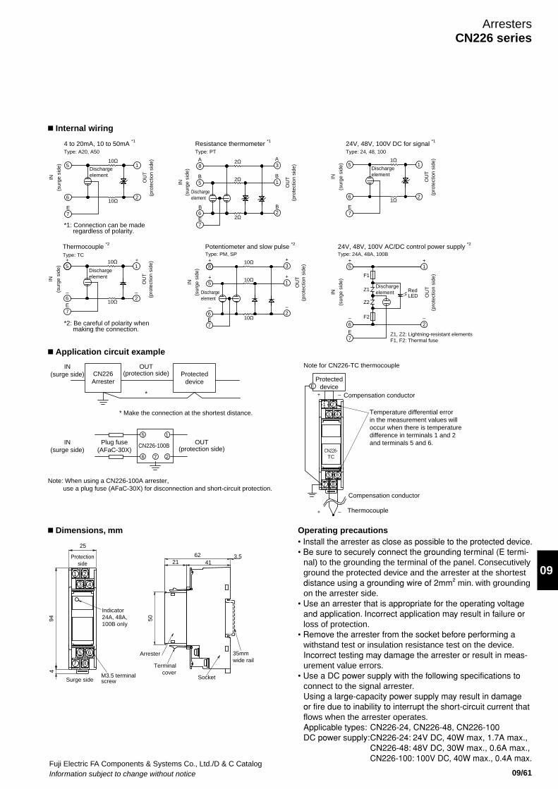
Fuji Electric FA Components & Systems Co., Ltd./D & C CatalogInformation subject to change without notice 09/61
09
ArrestersCN226 series
n Internal wiring
n Application circuit example
n Dimensions, mm Operating precautions
94
M3.5 terminalscrew
4
87
Surge side
5 6
25
2
3 4
1
Protectionside
50
Terminal cover
Arrester
624121
Socket
Indicator24A, 48A,100B only
35mmwide rail
3.5
IN(surge side)
Plug fuse(AFaC-30X)
CN226Arrester
Protecteddevice
OUT(protection side)
IN(surge side)
OUT(protection side)
*
6
5 1
27
CN226-100B
Compensation conductor
Thermocouple+ –
Compensation conductor–+E
Protecteddevice
Temperature differential errorin the measurement values willoccur when there is temperaturedifference in terminals 1 and 2and terminals 5 and 6.
7
5 6
3 4
1 2
CN226-TC
8
Note for CN226-TC thermocouple
Note: When using a CN226-100A arrester, use a plug fuse (AFaC-30X) for disconnection and short-circuit protection.
* Make the connection at the shortest distance.
*1: Connection can be made regardless of polarity.
*2: Be careful of polarity when making the connection.
E7
610Ω
2
(sur
ge s
ide)
4 to 20mA, 10 to 50mA *1
Type: A20, A50
Dischargeelement
510Ω
OU
T
1
IN
(pro
tect
ion
side
)
Thermocouple *2
Type: TC
7E6
(sur
ge s
ide) 5
10Ω2
10Ω
Dischargeelement
OU
T
1
IN
(pro
tect
ion
side
)
(sur
ge s
ide)
E6
10Ω2
Potentiometer and slow pulse *2
Type: PM, SP
5
Dischargeelement
8
10Ω
10Ω
1
OU
T
3
IN
(pro
tect
ion
side
)
7
E7
61Ω
2
(sur
ge s
ide)
Type: 24, 48, 100
Dischargeelement
51Ω
OU
T
1
IN
(pro
tect
ion
side
)
24V, 48V, 100V DC for signal *1
OU
T
(sur
ge s
ide)
E7
B6
2Ω
B2
Resistance thermometer *1
Type: PT
8
5B
A
2Ω
2Ω
1B
A3
IN
(pro
tect
ion
side
)
Dischargeelement
24V, 48V, 100V AC/DC control power supply *2
Type: 24A, 48A, 100B
E7
6
(sur
ge s
ide)
Z1, Z2: Lightning-resistant elements F1, F2: Thermal fuse
5
OU
T
F1
F2
Z1
Z2
Dischargeelement Red
LED
+1
IN
(pro
tect
ion
side
)
2–
+
–
+
+
–
+
+
–
+
–
+
–
• Install the arrester as close as possible to the protected device. • Be sure to securely connect the grounding terminal (E termi-
nal) to the grounding the terminal of the panel. Consecutively ground the protected device and the arrester at the shortest distance using a grounding wire of 2mm2 min. with grounding on the arrester side.
• Use an arrester that is appropriate for the operating voltage and application. Incorrect application may result in failure or loss of protection.
• Remove the arrester from the socket before performing a withstand test or insulation resistance test on the device. Incorrect testing may damage the arrester or result in meas-urement value errors.
• Use a DC power supply with the following specifications to connect to the signal arrester. Using a large-capacity power supply may result in damage or fire due to inability to interrupt the short-circuit current that flows when the arrester operates.
Applicable types: CN226-24, CN226-48, CN226-100 DC power supply: CN226-24: 24V DC, 40W max, 1.7A max., CN226-48: 48V DC, 30W max., 0.6A max., CN226-100: 100V DC, 40W max., 0.4A max.
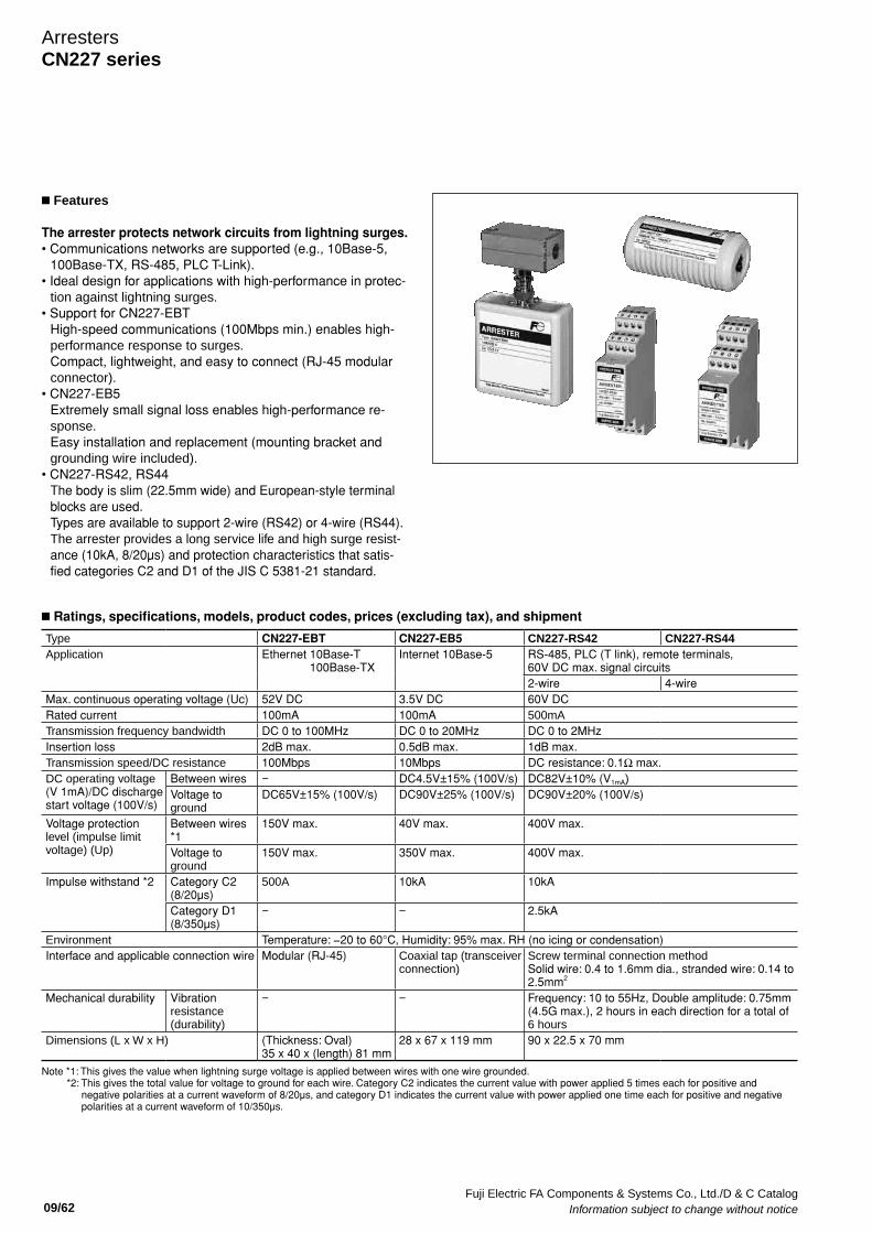
Fuji Electric FA Components & Systems Co., Ltd./D & C Catalog Information subject to change without notice 09/62
Type CN227-EBT CN227-EB5 CN227-RS42 CN227-RS44Application Ethernet 10Base-T
100Base-TXInternet 10Base-5 RS-485, PLC (T link), remote terminals,
60V DC max. signal circuits2-wire 4-wire
Max. continuous operating voltage (Uc) 52V DC 3.5V DC 60V DCRated current 100mA 100mA 500mATransmission frequency bandwidth DC 0 to 100MHz DC 0 to 20MHz DC 0 to 2MHzInsertion loss 2dB max. 0.5dB max. 1dB max. Transmission speed/DC resistance 100Mbps 10Mbps DC resistance: 0.1Ω max.DC operating voltage (V 1mA)/DC discharge start voltage (100V/s)
Between wires − DC4.5V±15% (100V/s) DC82V±10% (V1mA)Voltage to ground
DC65V±15% (100V/s) DC90V±25% (100V/s) DC90V±20% (100V/s)
Voltage protection level (impulse limit voltage) (Up)
Between wires *1
150V max. 40V max. 400V max.
Voltage to ground
150V max. 350V max. 400V max.
Impulse withstand *2 Category C2 (8/20µs)
500A 10kA 10kA
Category D1 (8/350µs)
− − 2.5kA
Environment Temperature: −20 to 60°C, Humidity: 95% max. RH (no icing or condensation)Interface and applicable connection wire Modular (RJ-45) Coaxial tap (transceiver
connection)Screw terminal connection method Solid wire: 0.4 to 1.6mm dia., stranded wire: 0.14 to 2.5mm2
Mechanical durability Vibration resistance (durability)
− − Frequency: 10 to 55Hz, Double amplitude: 0.75mm (4.5G max.), 2 hours in each direction for a total of 6 hours
Dimensions (L x W x H) (Thickness: Oval) 35 x 40 x (length) 81 mm
28 x 67 x 119 mm 90 x 22.5 x 70 mm
Note *1: This gives the value when lightning surge voltage is applied between wires with one wire grounded. *2: This gives the total value for voltage to ground for each wire. Category C2 indicates the current value with power applied 5 times each for positive and
negative polarities at a current waveform of 8/20µs, and category D1 indicates the current value with power applied one time each for positive and negative polarities at a current waveform of 10/350µs.
n Features
The arrester protects network circuits from lightning surges. • Communications networks are supported (e.g., 10Base-5,
100Base-TX, RS-485, PLC T-Link). • Ideal design for applications with high-performance in protec-
tion against lightning surges. • Support for CN227-EBT
High-speed communications (100Mbps min.) enables high-performance response to surges. Compact, lightweight, and easy to connect (RJ-45 modular connector).
• CN227-EB5 Extremely small signal loss enables high-performance re-sponse. Easy installation and replacement (mounting bracket and grounding wire included).
• CN227-RS42, RS44 The body is slim (22.5mm wide) and European-style terminal blocks are used. Types are available to support 2-wire (RS42) or 4-wire (RS44). The arrester provides a long service life and high surge resist-ance (10kA, 8/20µs) and protection characteristics that satis-fied categories C2 and D1 of the JIS C 5381-21 standard.
n Ratings, specifications, models, product codes, prices (excluding tax), and shipment
ArrestersCN227 series
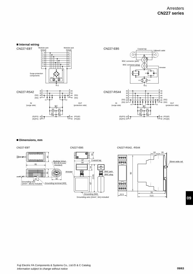
Fuji Electric FA Components & Systems Co., Ltd./D & C CatalogInformation subject to change without notice 09/63
09
Coaxial tap10Base5 cable
E
Arrester
BNC connector (jack)
BNC connector (plug)
4
123
5
76
8
4
123
5
76
8
E
Surge protectioncomponents
Modular jack(in/out)
Modular jack(in/out)
321
46
5
7
D1 D2MOV3
GDT1GDT2
8
CBA
DF
E
G
H
IN(surge side)
OUT(protection side)
(E)(FG)(E)(FG)
(SG)(SG)
(FG)(E)(FG)(E)
(SG)(SG)
CN227-EB5
CN227-RS42 CN227-RS44
CN227-EBT
MOV2 MOV1
GDT MOV
NRD NR
146
5
7
D1
D
TSS
D2
MOV3
GDT1GDT2
8
ADF
E
G
H
IN(surge side)
OUT(protection side)
(E)(FG)(E)(FG)
(SG)(SG)
(FG)(E)(FG)(E)
(SG)(SG)
MOV2 MOV1
Grounding (M4)
67
Arrester
(119
)28
Coaxial tap
24
50
67
BNC plug
BNC jack
Grounding wire (2mm2, 3m) included
81
Grounding wire(2mm2, 30cm) included
Modular in/out (RJ-45 8-core, shielded)
Grounding terminal (M3)
4035
22 40
90
70
72.5
35mm wide rail
22.5
19 20
CN227-EBT CN227-EB5 CN227-RS42, -RS44
n Internal wiring
n Dimensions, mm
ArrestersCN227 series
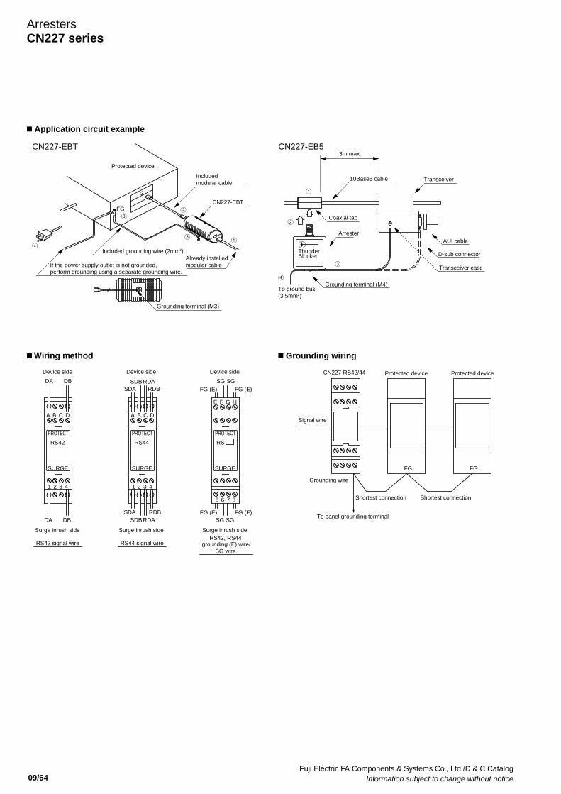
Fuji Electric FA Components & Systems Co., Ltd./D & C Catalog Information subject to change without notice 09/64
ArrestersCN227 series
CN227-RS42/44 Protected device Protected device
Shortest connection Shortest connection
To panel grounding terminal
Signal wire
Grounding wire
FG FG
PROTECT
SURGE SURGE
PROTECT
RS44RS42
SDBSDA
RDARDB
SDB RDASDA RDB
DA DB
DA DB
RS44 signal wireRS42 signal wire
Surge inrush side Surge inrush side
Device side Device side
Surge inrush side
Device side
grounding (E) wire/SG wire
SG
SURGE
RS
PROTECT
SG
FG (E) FG (E)
FG (E) FG (E)
SG SG
A B C DA B C D
E F G H
1 2 3 41 2 3 4
5 6 7 8
RS42, RS44
FG
Protected device
If the power supply outlet is not grounded,perform grounding using a separate grounding wire.
④
CN227-EBT
Included grounding wire (2mm2) Already installedmodular cable
Includedmodular cable
③
③
②
①
Grounding terminal (M3)
CN227-EBT
Thunder Blocker
3m max.
10Base5 cable
AUI cable
D-sub connector
Transceiver case
Transceiver
①
②
④
To ground bus(3.5mm2)
Grounding terminal (M4)
Arrester
Coaxial tap
③
CN227-EB5
n Wiring method
n Application circuit example
n Grounding wiring
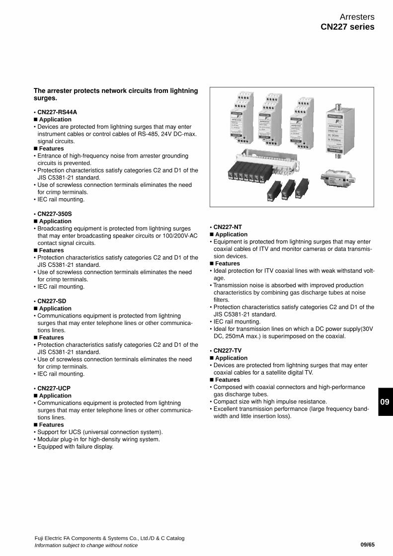
Fuji Electric FA Components & Systems Co., Ltd./D & C CatalogInformation subject to change without notice 09/65
09
ArrestersCN227 series
The arrester protects network circuits from lightning surges.
• CN227-RS44An Application• Devices are protected from lightning surges that may enter
instrument cables or control cables of RS-485, 24V DC-max. signal circuits.
n Features • Entrance of high-frequency noise from arrester grounding
circuits is prevented. • Protection characteristics satisfy categories C2 and D1 of the
JIS C5381-21 standard. • Use of screwless connection terminals eliminates the need
for crimp terminals. • IEC rail mounting.
• CN227-350Sn Application• Broadcasting equipment is protected from lightning surges
that may enter broadcasting speaker circuits or 100/200V-AC contact signal circuits.
n Features • Protection characteristics satisfy categories C2 and D1 of the
JIS C5381-21 standard. • Use of screwless connection terminals eliminates the need
for crimp terminals. • IEC rail mounting.
• CN227-SDn Application• Communications equipment is protected from lightning
surges that may enter telephone lines or other communica-tions lines.
n Features • Protection characteristics satisfy categories C2 and D1 of the
JIS C5381-21 standard. • Use of screwless connection terminals eliminates the need
for crimp terminals. • IEC rail mounting.
• CN227-UCPn Application• Communications equipment is protected from lightning
surges that may enter telephone lines or other communica-tions lines.
n Features • Support for UCS (universal connection system). • Modular plug-in for high-density wiring system. • Equipped with failure display.
• CN227-NTn Application• Equipment is protected from lightning surges that may enter
coaxial cables of ITV and monitor cameras or data transmis-sion devices.
n Features • Ideal protection for ITV coaxial lines with weak withstand volt-
age. • Transmission noise is absorbed with improved production
characteristics by combining gas discharge tubes at noise filters.
• Protection characteristics satisfy categories C2 and D1 of the JIS C5381-21 standard.
• IEC rail mounting. • Ideal for transmission lines on which a DC power supply(30V
DC, 250mA max.) is superimposed on the coaxial.
• CN227-TVn Application• Devices are protected from lightning surges that may enter
coaxial cables for a satellite digital TV. n Features • Composed with coaxial connectors and high-performance
gas discharge tubes. • Compact size with high impulse resistance. • Excellent transmission performance (large frequency band-
width and little insertion loss).
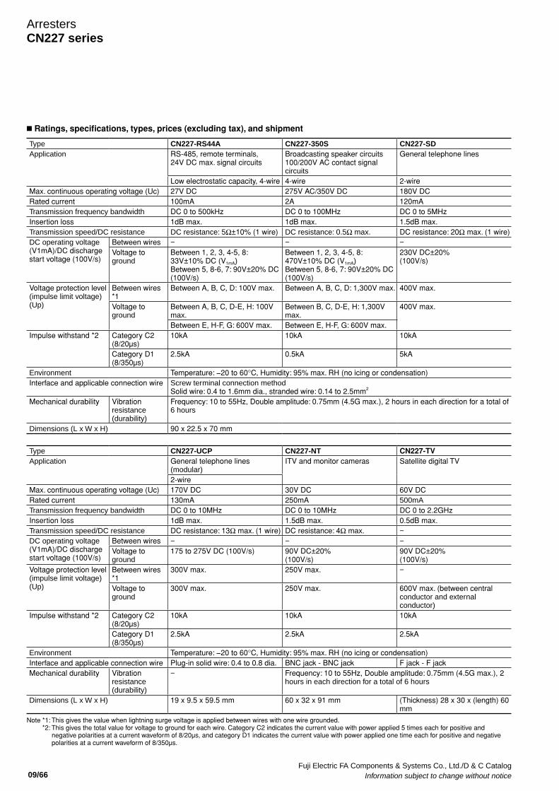
Fuji Electric FA Components & Systems Co., Ltd./D & C Catalog Information subject to change without notice 09/66
ArrestersCN227 series
Type CN227-RS44A CN227-350S CN227-SDApplication RS-485, remote terminals,
24V DC max. signal circuitsBroadcasting speaker circuits 100/200V AC contact signal circuits
General telephone lines
Low electrostatic capacity, 4-wire 4-wire 2-wire Max. continuous operating voltage (Uc) 27V DC 275V AC/350V DC 180V DCRated current 100mA 2A 120mATransmission frequency bandwidth DC 0 to 500kHz DC 0 to 100MHz DC 0 to 5MHzInsertion loss 1dB max. 1dB max. 1.5dB max. Transmission speed/DC resistance DC resistance: 5Ω±10% (1 wire) DC resistance: 0.5Ω max. DC resistance: 20Ω max. (1 wire) DC operating voltage (V1mA)/DC discharge start voltage (100V/s)
Between wires − − −Voltage to ground
Between 1, 2, 3, 4-5, 8: 33V±10% DC (V1mA) Between 5, 8-6, 7: 90V±20% DC (100V/s)
Between 1, 2, 3, 4-5, 8: 470V±10% DC (V1mA) Between 5, 8-6, 7: 90V±20% DC (100V/s)
230V DC±20%(100V/s)
Voltage protection level (impulse limit voltage) (Up)
Between wires *1
Between A, B, C, D: 100V max. Between A, B, C, D: 1,300V max. 400V max.
Voltage to ground
Between A, B, C, D-E, H: 100V max.
Between B, C, D-E, H: 1,300V max.
400V max.
Between E, H-F, G: 600V max. Between E, H-F, G: 600V max. Impulse withstand *2 Category C2
(8/20µs)10kA 10kA 10kA
Category D1 (8/350µs)
2.5kA 0.5kA 5kA
Environment Temperature: −20 to 60°C, Humidity: 95% max. RH (no icing or condensation)Interface and applicable connection wire Screw terminal connection method
Solid wire: 0.4 to 1.6mm dia., stranded wire: 0.14 to 2.5mm2
Mechanical durability Vibration resistance (durability)
Frequency: 10 to 55Hz, Double amplitude: 0.75mm (4.5G max.), 2 hours in each direction for a total of 6 hours
Dimensions (L x W x H) 90 x 22.5 x 70 mm
Type CN227-UCP CN227-NT CN227-TVApplication General telephone lines
(modular) ITV and monitor cameras Satellite digital TV
2-wire Max. continuous operating voltage (Uc) 170V DC 30V DC 60V DCRated current 130mA 250mA 500mATransmission frequency bandwidth DC 0 to 10MHz DC 0 to 10MHz DC 0 to 2.2GHzInsertion loss 1dB max. 1.5dB max. 0.5dB max. Transmission speed/DC resistance DC resistance: 13Ω max. (1 wire) DC resistance: 4Ω max. −DC operating voltage (V1mA)/DC discharge start voltage (100V/s)
Between wires − − −Voltage to ground
175 to 275V DC (100V/s) 90V DC±20%(100V/s)
90V DC±20%(100V/s)
Voltage protection level (impulse limit voltage) (Up)
Between wires *1
300V max. 250V max. −
Voltage to ground
300V max. 250V max. 600V max. (between central conductor and external conductor)
Impulse withstand *2 Category C2 (8/20µs)
10kA 10kA 10kA
Category D1 (8/350µs)
2.5kA 2.5kA 2.5kA
Environment Temperature: −20 to 60°C, Humidity: 95% max. RH (no icing or condensation)Interface and applicable connection wire Plug-in solid wire: 0.4 to 0.8 dia. BNC jack - BNC jack F jack - F jackMechanical durability Vibration
resistance (durability)
− Frequency: 10 to 55Hz, Double amplitude: 0.75mm (4.5G max.), 2 hours in each direction for a total of 6 hours
Dimensions (L x W x H) 19 x 9.5 x 59.5 mm 60 x 32 x 91 mm (Thickness) 28 x 30 x (length) 60 mm
Note *1: This gives the value when lightning surge voltage is applied between wires with one wire grounded. *2: This gives the total value for voltage to ground for each wire. Category C2 indicates the current value with power applied 5 times each for positive and
negative polarities at a current waveform of 8/20µs, and category D1 indicates the current value with power applied one time each for positive and negative polarities at a current waveform of 8/350µs.
n Ratings, specifications, types, prices (excluding tax), and shipment
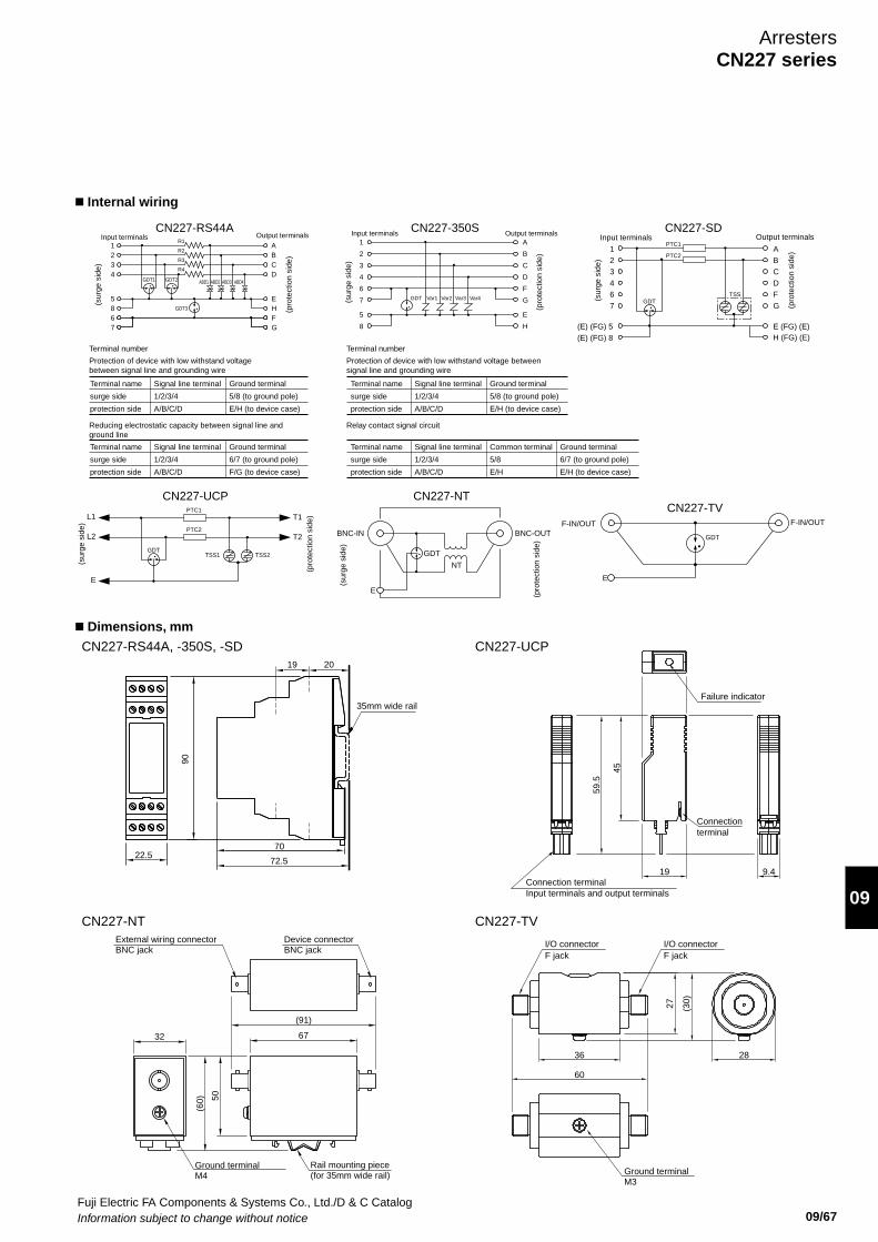
Fuji Electric FA Components & Systems Co., Ltd./D & C CatalogInformation subject to change without notice 09/67
09
F-IN/OUT F-IN/OUT
GDT
E
CN227-TV
Input terminals Output terminals
123467
ABCDF
G
PTC1
PTC2
GDTTSS
(E) (FG) 5(E) (FG) 8
E (FG) (E)H (FG) (E)
GDTTSS1 TSS2
CN227-SD
(sur
ge s
ide)
(pro
tect
ion
side
)
L1
E
T1PTC1
L2 T2PTC2
CN227-UCP
(sur
ge s
ide)
(pro
tect
ion
side
)GDT Var1 Var2 Var3 Var4
Input terminals1
2
3
4
6
7
5
8
Output terminalsA
B
C
D
F
G
E
H
CN227-350S
(sur
ge s
ide)
(pro
tect
ion
side
)
ABD1 ABD2 ABD3 ABD4
Input terminals Output terminalsR1
R2
R3
R4
1234
5867
ABCD
EHFG
GDT3
GDT2GDT1
CN227-RS44A
(sur
ge s
ide)
(pro
tect
ion
side
)
NT
BNC-IN BNC-OUT
GDT
E
CN227-NT
(sur
ge s
ide)
(pro
tect
ion
side
)
Protection of device with low withstand voltagebetween signal line and grounding wire
Terminal number
Terminal name
surge side
protection side
Signal line terminal
1/2/3/4
A/B/C/D
Ground terminal
5/8 (to ground pole)
E/H (to device case)
Reducing electrostatic capacity between signal line andground line
Terminal name
surge side
protection side
Signal line terminal
1/2/3/4
A/B/C/D
Ground terminal
6/7 (to ground pole)
F/G (to device case)
Protection of device with low withstand voltage betweensignal line and grounding wire
Terminal number
Terminal name
surge side
protection side
Signal line terminal
1/2/3/4
A/B/C/D
Ground terminal
5/8 (to ground pole)
E/H (to device case)
Relay contact signal circuit
Terminal name
surge side
protection side
Signal line terminal
1/2/3/4
A/B/C/D
Common terminal
5/8
E/H
Ground terminal
6/7 (to ground pole)
E/H (to device case)
90
70
27 (30)
2836
60
72.5
59.5
45
19 9.4
35mm wide rail
(91)
67
50
(60)
Device connector BNC jack
External wiring connector BNC jack
Ground terminalM4
Rail mounting piece(for 35mm wide rail) Ground terminal
M3
I/O connector F jack
I/O connector F jack
Connection terminal Input terminals and output terminals
Connectionterminal
Failure indicator
22.5
19 20
CN227-RS44A, -350S, -SD
CN227-NT
CN227-UCP
CN227-TV
32
n Internal wiring
n Dimensions, mm
ArrestersCN227 series
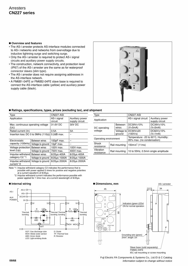
Fuji Electric FA Components & Systems Co., Ltd./D & C Catalog Information subject to change without notice 09/68
ArrestersCN227 series
AS-i+
AS-i-
DC24V
0V
E
AS-i
TF
ABD
R R
ABD
MOV MOV
LED
D
GDT
LED
Thermalbonding
GDT: Gas discharge tube MOV: Metal oxide varistor ABD: Zener diode LED: Light-emitting diode
D: Diode TF: Thermal fuse R: Resistor
Thermalbonding
Thermalbonding
Thermalbonding
TF TFTF
AUXPOWER
AS-i
CN227-ASIE
AUXPOW
Indicators (green LEDs) ON for normal operation
AS-i arrester
Slave base (sold separately) FM6B1-04FE IEC rail mounting or screw mounting
Grounding wire (green) 2mm2, length: 1m
(12.3) 34
80
45
Type CN227-ASIApplication AS-i signal
circuitAuxiliary power supply circuit
Max. continuous operating voltage (Uc)
31.6V DC 30V DC
Rated current (In) 0.5A 5AInsertion loss: DC 0 to 5MHz (110Ω) 0.2dB max. −
Electrostatic capacity (100kHz)
Between wires 100pF max. −Voltage to ground 10pF max. −
Voltage protection level (Up)
Between wires 100V max. 100V max. Voltage to ground 700V max. 400V max.
Impulse withstand category C2 *1
Between wires 8/20µs 400A 8/20µs 400AVoltage to ground 8/20µs 1000A 8/20µs 1000A
Impulse withstand current *2
Voltage to ground 8/20µs 2000A 8/20µs 2000A
Note *1: Impulse withstand category C2 indicates the performance that is possible with power applied 5 times for positive and negative polarities at a current waveform of 8/20µs.
Note *2: Impulse withstand current indicates the performance possible with power applied for 1 time max. at a current wavelength of 8/20µs.
Type CN227-ASI
Application AS-i signal circuit Auxiliary power supply circuit
DC operating voltage
Between wires
DC39V±10% (V=5mA)
DC39V±10% (V=5mA)
Voltage to ground
DC90V±20 (100V/s)
DC82V±10% (V=1mA)
Operating environment Temperature: -20 to 60°C, Humidity: 95% max. (no condensation)
Shock resistance Rail mounting 150m/s2 (11ms)
Vibration resistance Rail mounting 10 to 55Hz, 0.5mm single amplitude
n Overview and features • The AS-i arrester protects AS-interface modules connected
to AS-i networks and networks from overvoltage due to inductive lightning surge and switching surge.
• Only the AS-i arrester is required to protect AS-i signal circuits and auxiliary power supply circuits.
• The construction, network connectivity, and protection level (IP67) of the AS-i arrester are the same as for waterproof connector slaves (slim type).
• The AS-i arrester does not require assigning addresses in the AS-interface network.
• A FM6B1-04FE or FM6B2-04FE slave base is required to connect the AS-interface cable (yellow) and auxiliary power supply cable (black).
n Ratings, specifications, types, prices (excluding tax), and shipment
n Internal wiring n Dimensions, mm
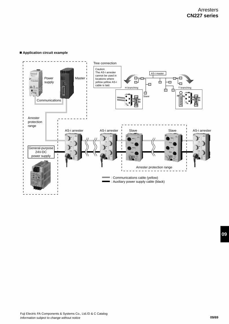
Fuji Electric FA Components & Systems Co., Ltd./D & C CatalogInformation subject to change without notice 09/69
09
n Application circuit example
AS-i master
Tree connection
Slave
H branching T branching
: Communications cable (yellow): Auxiliary power supply cable (black)
MasterPowersupply
Communications
AS-i arrester AS-i arrester AS-i arrester Slave Slave
Arresterprotectionrange
Arrester protection range
General-purpose24V-DC
power supply
Caution The AS-i arrester cannot be used in locations where yellow-yellow AS-i cable is laid.
Arr
este
r
Arr
este
r
Arr
este
r
ArrestersCN227 series
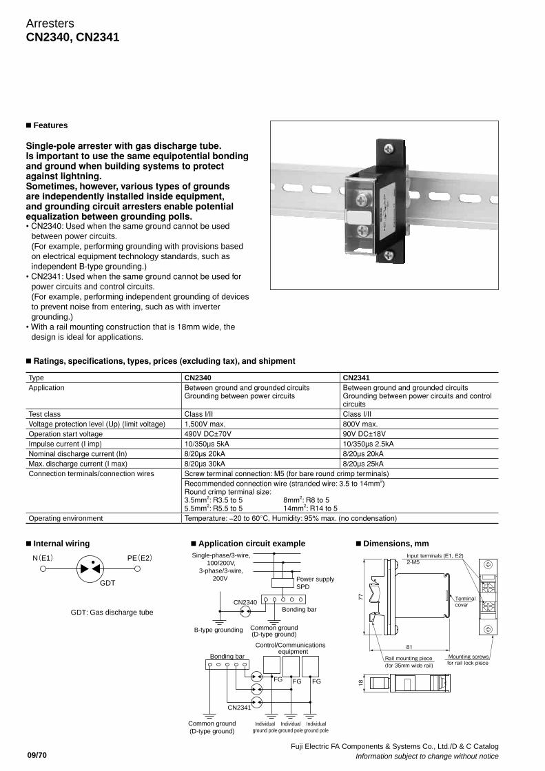
Fuji Electric FA Components & Systems Co., Ltd./D & C Catalog Information subject to change without notice 09/70
ArrestersCN2340, CN2341
n Ratings, specifications, types, prices (excluding tax), and shipment
n Internal wiring n Application circuit example n Dimensions, mm
Type CN2340 CN2341Application Between ground and grounded circuits
Grounding between power circuitsBetween ground and grounded circuits Grounding between power circuits and control circuits
Test class Class I/II Class I/II Voltage protection level (Up) (limit voltage) 1,500V max. 800V max. Operation start voltage 490V DC±70V 90V DC±18VImpulse current (I imp) 10/350µs 5kA 10/350µs 2.5kANominal discharge current (In) 8/20µs 20kA 8/20µs 20kAMax. discharge current (I max) 8/20µs 30kA 8/20µs 25kAConnection terminals/connection wires Screw terminal connection: M5 (for bare round crimp terminals)
Recommended connection wire (stranded wire: 3.5 to 14mm2) Round crimp terminal size: 3.5mm2: R3.5 to 5 8mm2: R8 to 5 5.5mm2: R5.5 to 5 14mm2: R14 to 5
Operating environment Temperature: −20 to 60°C, Humidity: 95% max. (no condensation)
N(E1) PE(E2)
GDT
GDT: Gas discharge tube
Input terminals (E1, E2) 2-M5
Mounting screwsfor rail lock piece
Rail mounting piece(for 35mm wide rail)
77
18
81
Terminalcover
Single-phase/3-wire,100/200V,
3-phase/3-wire,200V Power supply
SPD
Bonding bar
Control/Communications equipment
Bonding bar
Common ground(D-type ground)
Common ground(D-type ground)
Individualground pole
Individualground pole
B-type grounding
CN2340
CN2341
FGFG
Individualground pole
FG
n Features
Single-pole arrester with gas discharge tube.Is important to use the same equipotential bonding and ground when building systems to protect against lightning. Sometimes, however, various types of grounds are independently installed inside equipment, and grounding circuit arresters enable potential equalization between grounding polls. • CN2340: Used when the same ground cannot be used
between power circuits. (For example, performing grounding with provisions based on electrical equipment technology standards, such as independent B-type grounding.)
• CN2341: Used when the same ground cannot be used for power circuits and control circuits. (For example, performing independent grounding of devices to prevent noise from entering, such as with inverter grounding.)
• With a rail mounting construction that is 18mm wide, the design is ideal for applications.
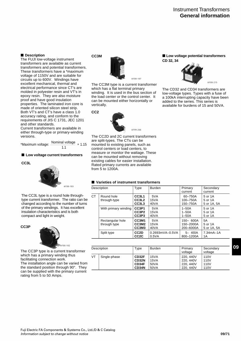
Fuji Electric FA Components & Systems Co., Ltd./D & C CatalogInformation subject to change without notice
09
09/71
DescriptionThe FUJI low-voltage instrumenttransformers are available as currenttransformers and potential transformers.These transformers have a *maximumvoltage of 1150V and are suitable forcircuits up to 600V. Windings haveexcellent mechanical, thermal andelectrical performance since CT's aremolded in polyester resin and VT's inepoxy resin. They are also moistureproof and have good insulationproperties. The laminated iron core ismade of oriented silicon steel strip.Both VT's and CT's have a class 1.0accuracy rating, and conform to therequirements of JIS C 1731, JEC 1201and other standards.Current transformers are available ineither through-type or primary-windingversions.
*Maximum voltage: × 1.15
Instrument TransformersGeneral information
CC3P
The CC3P type is a current transformerwhich has a primary winding thusfacilitating connection work.The installation angle can be varied fromthe standard position through 90°. Theycan be supplied with the primary currentrating from 5 to 50 Amps.
Low voltage potential transformersCD 32, 34
The CD32 and CD34 transformers arelow-voltage types. Types with a fuse ofa 100kA interrupting capacity have beenadded to the series. This series isavailable for burdens of 15 and 50VA.
Varieties of instrument transformers
Nominal voltage1.1
AF00-103
AF00-102
AF00-215
Low voltage current transformers
CC3L
The CC3L type is a round hole through-type current transformer. The ratio can bechanged according to the number of turnsof the primary windings. It has excellentinsulation characteristics and is bothcompact and light in weight.
CC2
The CC2D and 2C current transformersare split-types. The CTs can bemounted to existing panels, such ascontrol centers or load centers, tomeasure or monitor the wattage. Thesecan be mounted without removingexisting cables for easier installation.Rated primary currents are availablefrom 5 to 1200A.
AF99-266
CC3M
The CC3M type is a current transformerwhich has a flat terminal primarywinding. It is used in the bus section ofthe load center or the control center. Itcan be mounted either horizontally orvertically.
AF00-107
Description Type Burden Primary Secondarycurrent current
CT Round hole CC3L1 5VA 60–750A 5 or 1Athrough-type CC3L2 15VA 100–750A 5 or 1A
CC3L3 40VA 150–750A 5 or 1A, 5A
With primary winding CC3P1 5VA 1–50A 5 or 1ACC3P2 15VA 1–50A 5 or 1ACC3P3 40VA 1–50A 5 or 1A
Rectangular hole CC3M1 5VA 150– 600A 5Athrough type CC3M2 15VA 150–2000A 5 or 1A
CC3M3 40VA 200–6000A 5 or 1A, 5A
Split type CC2D 0.2693mVA–0.5VA 5– 400A 7.34mA–1ACC2C 0.5VA 800–1200A 1A
Description Type Burden Primary Secondaryvoltage voltage
VT Single-phase CD32F 15VA 220, 440V 110VCD32N 15VA 220, 440V 110VCD34F 50VA 220, 440V 110VCD34N 50VA 220, 440V 110V
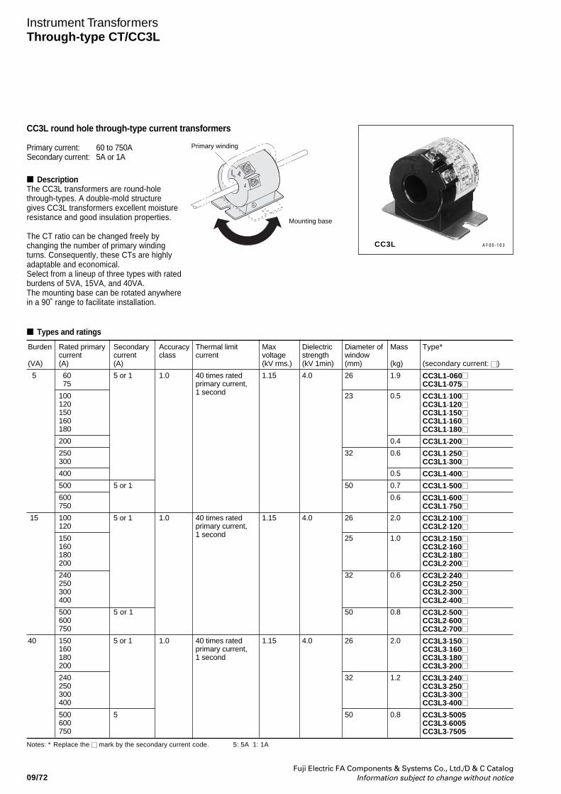
09/72Fuji Electric FA Components & Systems Co., Ltd./D & C Catalog
Information subject to change without notice
Secondarycurrent(A)
5 or 1
5 or 1
5 or 1
5 or 1
5 or 1
5
Rated primarycurrent(A)
60 75
100120150160180
200
250300
400
500
600750
100120
150160180200
240250300400
500600750
150160180200
240250300400
500600750
Type*
(secondary current: )
CC3L1-060CC3L1-075
CC3L1-100CC3L1-120CC3L1-150CC3L1-160CC3L1-180
CC3L1-200
CC3L1-250CC3L1-300
CC3L1-400
CC3L1-500
CC3L1-600CC3L1-750
CC3L2-100CC3L2-120
CC3L2-150CC3L2-160CC3L2-180CC3L2-200
CC3L2-240CC3L2-250CC3L2-300CC3L2-400
CC3L2-500CC3L2-600CC3L2-700
CC3L3-150CC3L3-160CC3L3-180CC3L3-200
CC3L3-240CC3L3-250CC3L3-300CC3L3-400
CC3L3-5005CC3L3-6005CC3L3-7505
Instrument TransformersThrough-type CT/CC3L
CC3L round hole through-type current transformers
Primary current: 60 to 750ASecondary current: 5A or 1A
Accuracyclass
1.0
1.0
1.0
Thermal limitcurrent
40 times ratedprimary current,1 second
40 times ratedprimary current,1 second
40 times ratedprimary current,1 second
Maxvoltage(kV rms.)
1.15
1.15
1.15
Burden
(VA)
5
15
40
AF00-103
Notes: * Replace the mark by the secondary current code.
Types and ratings
Primary winding
Mounting base
Diameter ofwindow(mm)
26
23
32
50
26
25
32
50
26
32
50
Mass
(kg)
1.9
0.5
0.4
0.6
0.5
0.7
0.6
2.0
1.0
0.6
0.8
2.0
1.2
0.8
CC3L
DescriptionThe CC3L transformers are round-holethrough-types. A double-mold structuregives CC3L transformers excellent moistureresistance and good insulation properties.
The CT ratio can be changed freely bychanging the number of primary windingturns. Consequently, these CTs are highlyadaptable and economical.Select from a lineup of three types with ratedburdens of 5VA, 15VA, and 40VA.The mounting base can be rotated anywherein a 90˚ range to facilitate installation.
Dielectricstrength(kV 1min)
4.0
4.0
4.0
5: 5A 1: 1A
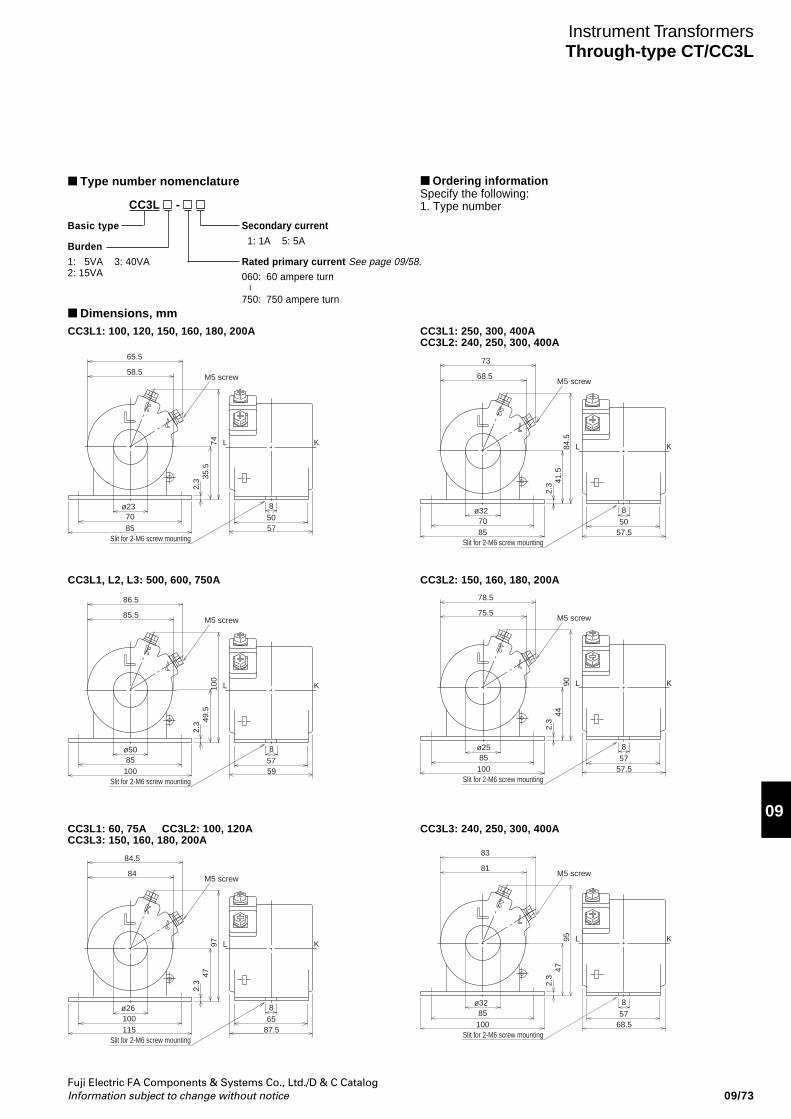
Fuji Electric FA Components & Systems Co., Ltd./D & C CatalogInformation subject to change without notice
09
09/73
Instrument TransformersThrough-type CT/CC3L
Type number nomenclature
CC3L -
Secondary current 1: 1A 5: 5A
Rated primary current See page 09/58.060: 60 ampere turn
750: 750 ampere turn
Basic type
Burden1: 5VA 3: 40VA2: 15VA
CC3L1: 100, 120, 150, 160, 180, 200A
65.5
58.5M5 screw
85 57508
L K
35.5
2.3
74
70
Slit for 2-M6 screw mounting
ø23
CC3L1: 250, 300, 400ACC3L2: 240, 250, 300, 400A
CC3L1, L2, L3: 500, 600, 750A CC3L2: 150, 160, 180, 200A
CC3L1: 60, 75A CC3L2: 100, 120ACC3L3: 150, 160, 180, 200A
CC3L3: 240, 250, 300, 400A
73
68.5M5 screw
85 57.5508
L K
41.5
2.3
84.5
70
Slit for 2-M6 screw mounting
ø32
86.5
85.5M5 screw
100 59578
L K
49.5
2.3
100
85
Slit for 2-M6 screw mounting
ø50
78.5
75.5M5 screw
100 57.5578
L K
442.
3
90
85
Slit for 2-M6 screw mounting
ø25
84.5
84M5 screw
115 87.5658
L K
472.
3
97
100
Slit for 2-M6 screw mounting
ø26
83
81M5 screw
100 68.5578
L K
472.
3
95
85
Slit for 2-M6 screw mounting
ø32
Dimensions, mm
Ordering informationSpecify the following:1. Type number
–
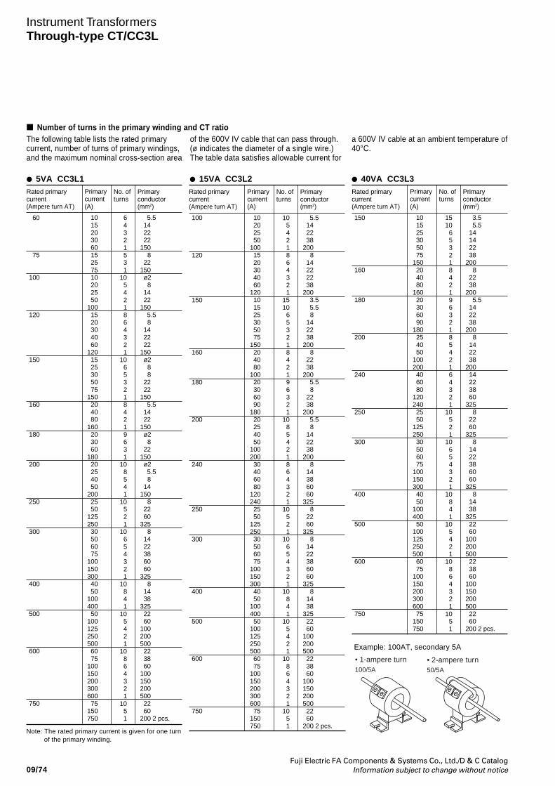
09/74Fuji Electric FA Components & Systems Co., Ltd./D & C Catalog
Information subject to change without notice
Instrument TransformersThrough-type CT/CC3L
Note: The rated primary current is given for one turnof the primary winding.
Rated primarycurrent(Ampere turn AT)
60
75
100
120
150
160
180
200
250
300
400
500
600
750
5VA CC3L1Primarycurrent(A)
10 15 20 30 60 15 25 75 10 20 25 50100 15 20 30 40 60120 15 25 30 50 75150 20 40 80160 20 30 60180 20 25 40 50200 25 50125250 30 50 60 75100150300 40 50100400 50100125250500 60 75100150200300600 75150750
No. ofturns
6 4 3 2 1 5 3 1 10 5 4 2 1 8 6 4 3 2 1 10 6 5 3 2 1 8 4 2 1 9 6 3 1 10 8 5 4 1 10 5 2 1 10 6 5 4 3 2 1 10 8 4 1 10 5 4 2 1 10 8 6 4 3 2 1 10 5 1
Primaryconductor(mm2)
5.5 14 22 22150 8 22150 ø2 8 14 22150 5.5 8 14 22 22150 ø2 8 8 22 22150 5.5 14 22150 ø2 8 22150 ø2 5.5 8 14150 8 22 60325 8 14 22 38 60 60325 8 14 38325 22 60100200500 22 38 60100150200500 22 60200 2 pcs.
Rated primarycurrent(Ampere turn AT)
150
160
180
200
240
250
300
400
500
600
750
Primarycurrent(A)
10 15 25 30 50 75150 20 40 80160 20 30 60 90180 25 40 50100200 40 60 80120240 25 50125250 30 50 60 75100150300 40 50100400 50100125250500 60 75100150200300600 75150750
No. ofturns
15 10 6 5 3 2 1 8 4 2 1 9 6 3 2 1 8 5 4 2 1 6 4 3 2 1 10 5 2 1 10 6 5 4 3 2 1 10 8 4 1 10 5 4 2 1 10 8 6 4 3 2 1 10 5 1
Primaryconductor(mm2)
3.5 5.5 14 14 22 38200 8 22 38200 5.5 14 22 38200 8 14 22 38200 14 22 38 60325 8 22 60325 8 14 22 38 60 60325 8 14 38325 22 60100200500 22 38 60100150200500 22 60200 2 pcs.
Rated primarycurrent(Ampere turn AT)
100
120
150
160
180
200
240
250
300
400
500
600
750
Primarycurrent(A)
10 20 25 50100 15 20 30 40 60120 10 15 25 30 50 75150 20 40 80100 20 30 60 90180 20 25 40 50100200 30 40 60 80120240 25 50125250 30 50 60 75100150300 40 50100400 50100125250500 60 75100150200300600 75150750
No. ofturns
10 5 4 2 1 8 6 4 3 2 1 15 10 6 5 3 2 1 8 4 2 1 9 6 3 2 1 10 8 5 4 2 1 8 6 4 3 2 1 10 5 2 1 10 6 5 4 3 2 1 10 8 4 1 10 5 4 2 1 10 8 6 4 3 2 1 10 5 1
Primaryconductor(mm2)
5.5 14 22 38200 8 14 22 22 38200 3.5 5.5 8 14 22 38200 8 22 38200 5.5 8 22 38200 5.5 8 14 22 38200 8 14 38 60 60325 8 22 60325 8 14 22 38 60 60325 8 14 38325 22 60100200500 22 38 60100150200500 22 60200 2 pcs.
Number of turns in the primary winding and CT ratioThe following table lists the rated primarycurrent, number of turns of primary windings,and the maximum nominal cross-section area
of the 600V IV cable that can pass through.(ø indicates the diameter of a single wire.)The table data satisfies allowable current for
a 600V IV cable at an ambient temperature of40°C.
15VA CC3L2 40VA CC3L3
• 1-ampere turn • 2-ampere turn100/5A 50/5A
Example: 100AT, secondary 5A
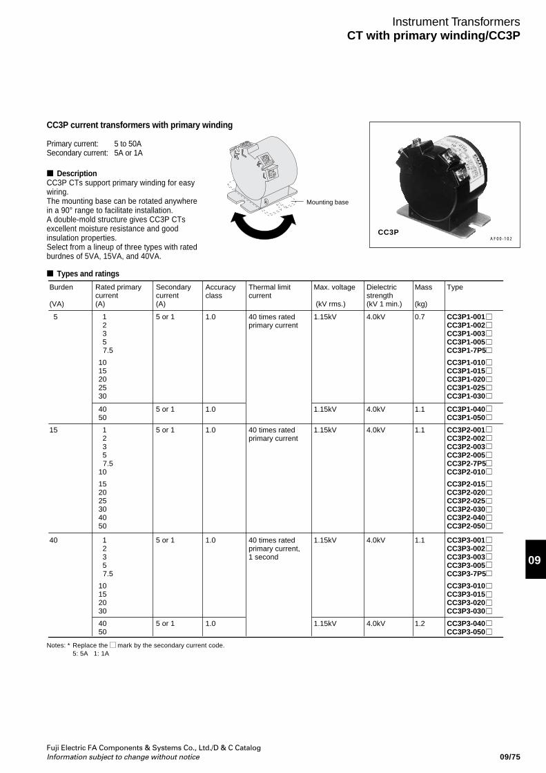
Fuji Electric FA Components & Systems Co., Ltd./D & C CatalogInformation subject to change without notice
09
09/75
Instrument TransformersCT with primary winding/CC3P
DescriptionCC3P CTs support primary winding for easywiring.The mounting base can be rotated anywherein a 90° range to facilitate installation.A double-mold structure gives CC3P CTsexcellent moisture resistance and goodinsulation properties.Select from a lineup of three types with ratedburdnes of 5VA, 15VA, and 40VA.
AF00-102
Notes: * Replace the mark by the secondary current code.5: 5A 1: 1A
Types and ratings
Mounting base
CC3P
Secondarycurrent(A)
5 or 1
5 or 1
5 or 1
5 or 1
5 or 1
Rated primarycurrent (A)
12357.5
10 15 2025
30
40 50
12357.5
10
15 2025
30 40 50
123
57.5
10 15 20 30
40 50
Type
CC3P1-001CC3P1-002CC3P1-003CC3P1-005CC3P1-7P5
CC3P1-010CC3P1-015CC3P1-020CC3P1-025CC3P1-030
CC3P1-040CC3P1-050
CC3P2-001CC3P2-002CC3P2-003CC3P2-005CC3P2-7P5CC3P2-010
CC3P2-015CC3P2-020CC3P2-025CC3P2-030CC3P2-040CC3P2-050
CC3P3-001CC3P3-002CC3P3-003CC3P3-005CC3P3-7P5
CC3P3-010CC3P3-015CC3P3-020CC3P3-030
CC3P3-040CC3P3-050
Accuracyclass
1.0
1.0
1.0
1.0
1.0
Thermal limitcurrent
40 times rated primary current
40 times rated primary current
40 times rated primary current,1 second
Max. voltage
(kV rms.)
1.15kV
1.15kV
1.15kV
1.15kV
1.15kV
4.0kV
4.0kV
4.0kV
4.0kV
4.0kV
Burden (VA)
5
15
40
Dielectricstrength (kV 1 min.)
Mass
(kg)
0.7
1.1
1.1
1.1
1.2
CC3P current transformers with primary winding
Primary current: 5 to 50ASecondary current: 5A or 1A
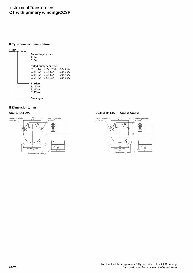
09/76Fuji Electric FA Components & Systems Co., Ltd./D & C Catalog
Information subject to change without notice
CC3P - Secondary current1: 1A5: 5A
Rated primary current
Burden1: 5VA2: 15VA3: 40VA
Basic type
Type number nomenclature
Dimensions, mm
CC3P1: 1 to 30A CC3P1: 40, 50A CC3P2, CC3P3
82
862.
3
508
57.585
70
69.5Primary terminal M5 screw
Secondary terminal M5 screw
Mounting pitch
2-M6 mounting screw
90.5
972.
3
578
69100
85
82.5Primary terminal M5 screw
Secondary terminal M5 screw
Mounting pitch
2-M6 mounting screw
001: 1A002: 2A003: 3A005: 5A
7P5: 7.5A010: 10A015: 15A020: 20A
025: 25A030: 30A040: 40A050: 50A
Instrument TransformersCT with primary winding/CC3P
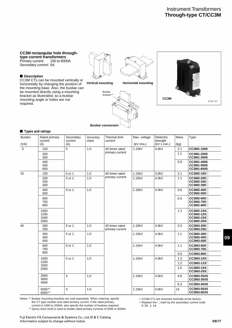
Fuji Electric FA Components & Systems Co., Ltd./D & C CatalogInformation subject to change without notice
09
09/77
Instrument TransformersThrough-type CT/CC3M
AF00-107
Notes: *1 Busbar mounting brackets are sold separately. When ordering, specifythe CT type number and rated primary current. If the rated primarycurrent is 1000 to 2000A, also specify the number of busbars required.
*2 Epoxy resin mold is used to isolate rated primary currents of 5000 or 6000A.
CC3M rectangular hole through-type current transformersPrimary current: 150 to 6000ASecondary current: 5A
DescriptionCC3M CTs can be mounted vertically orhorizontally by changing the position ofthe mounting base. Also, the busbar canbe mounted directly using a mountingbracket as illustrated, so a busbarmounting angle or holes are notrequired.
Vertical mounting Horizontal mounting
Busbar connectoin
Busbar bracket *1
CC3M
Types and ratings
Secondarycurrent(A)
5 or 1
5 or 1
5 or 1
5 or 1
5 or 1
5 or 1
5 or 1
5
5
Rated primarycurrent (A)
150
200 250 300
200 250
300 400 500
600 750 800
1000120015002000
250030004000
50006000
*2
*2
Type
CC3M2-150
CC3M2-200CC3M2-250CC3M2-300
CC3M2-400CC3M2-500
CC3M2-600CC3M2-750CC3M2-800
CC3M2-10XCC3M2-12XCC3M2-15XCC3M2-20X
400 500
600 750
800
1000120015002000
CC3M3-200CC3M3-250
CC3M3-300CC3M3-400CC3M3-500
CC3M3-600CC3M3-750
CC3M3-800
CC3M3-10X
CC3M3-12X
CC3M3-15XCC3M3-20X
CC3M3-25X5CC3M3-30X5
CC3M3-40X5
CC3M3-50X5CC3M3-60X5
Accuracyclass
1.0
1.0
1.0
1.0
1.0
1.0
1.0
1.0
1.0
Thermal limitcurrent
40 times rated primary current
40 times rated primary current
Max. voltage
(kV rms.)
1.15kV
1.15kV
1.15kV
1.15kV
1.15kV
1.15kV
1.15kV
1.15kV
1.15kV
Burden (VA)
15
40
Dielectricstrength (kV 1 min.)
4.0kV
4.0kV
4.0kV
4.0kV
4.0kV
4.0kV
4.0kV
4.0kV
4.0kV
Mass
(kg)
2.1
5 CC3M1-1505
CC3M1-2005CC3M1-3005CC3M1-4005CC3M1-5005CC3M1-6005
150
200300400500600
1.0 40 times rated primary current
1.15kV 5 4.0kV 2.1
1.1
0.6
1.2
0.5
2.3
1.1
1.1
0.9
1.3
1.2
1.5
1.1
0.6
4.8
6.3
14
• CC3M CTs are mounted vertically at the factory. • Replace the mark by the secondary current code.
5: 5A 1: 1A
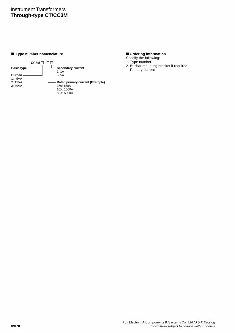
09/78Fuji Electric FA Components & Systems Co., Ltd./D & C Catalog
Information subject to change without notice
CC3M - Secondary current1: 1A5: 5A
Rated primary current (Example)150: 150A10X: 1000A50X: 5000A
Type number nomenclature
Basic type
Burden1: 5VA2: 15VA3: 40VA
Ordering informationSpecify the following:1. Type number2. Busbar mounting bracket if required. Primary current
Instrument TransformersThrough-type CT/CC3M
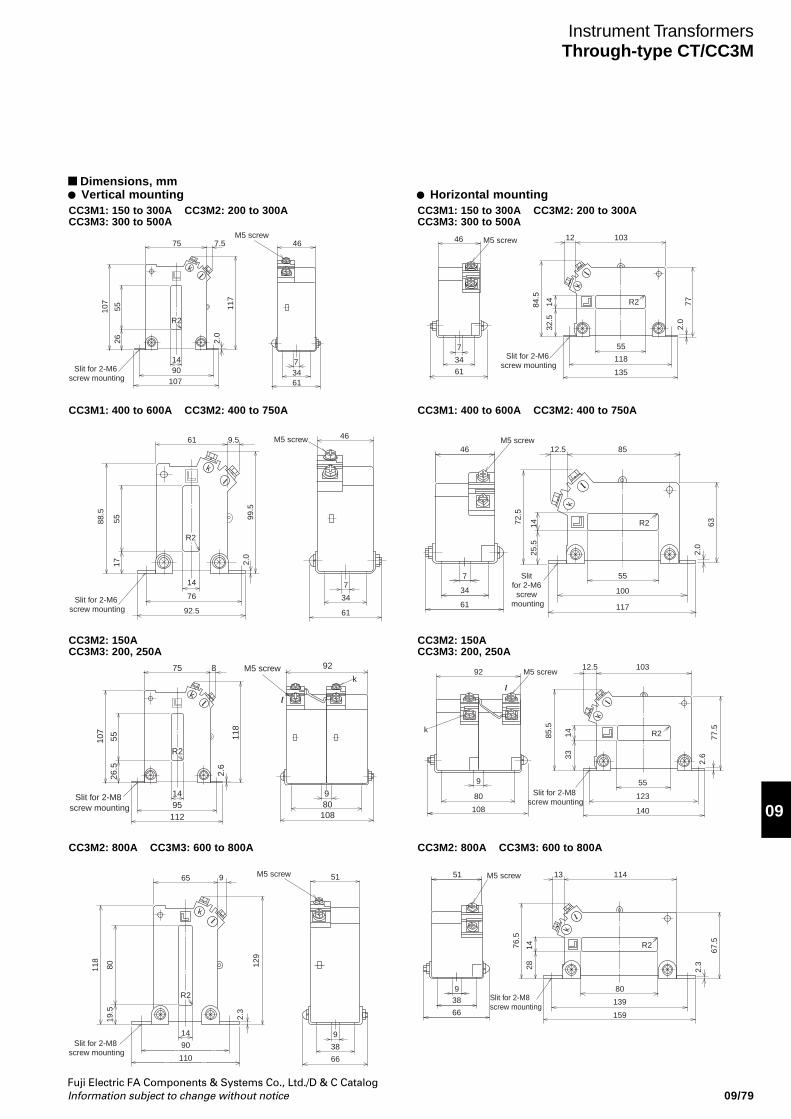
Fuji Electric FA Components & Systems Co., Ltd./D & C CatalogInformation subject to change without notice
09
09/79
Instrument TransformersThrough-type CT/CC3M
CC3M1: 150 to 300A CC3M2: 200 to 300ACC3M3: 300 to 500A
CC3M1: 150 to 300A CC3M2: 200 to 300ACC3M3: 300 to 500A
75 46
73461
7.5
R2
1490
107
Slit for 2-M6 screw mounting
107
5526 2.
0
117
k
M5 screw 46 M5 screw
7
34
61
12 103
55
118
135
Slit for 2-M6 screw mounting
84.5
1432
.5
2.0
77R2
k
CC3M1: 400 to 600A CC3M2: 400 to 750A CC3M1: 400 to 600A CC3M2: 400 to 750A
CC3M2: 150ACC3M3: 200, 250A
CC3M2: 150ACC3M3: 200, 250A
CC3M2: 800A CC3M3: 600 to 800A CC3M2: 800A CC3M3: 600 to 800A
61 46
7
34
61
9.5
14
76
92.5Slit for 2-M6
screw mounting
88.5
5517 2.
099
.5
k
M5 screw
R2
46M5 screw
7
34
61
12.5
72.5
63
2.0
1425
.5
55
100
85
R2
117
Slit for 2-M6 screw
mounting
k
75 8
R2
1495
112
Slit for 2-M8 screw mounting
107
5526
.5
2.6
118
k
M5 screw 92
980
108
k92 M5 screw
80
9
108
12.5 103
55
123
140
Slit for 2-M8 screw mounting
85.5
1433
2.6
77.5
R2
k
k
65
R2
14
90
110
9
k
118
80 129
19.5
2.3
Slit for 2-M8 screw mounting
M5 screw 51
9
38
66
51 M5 screw
938
66
13
76.5
67.5
2.3
1428
80
114
R2
139
159
Slit for 2-M8 screw mounting
k
Dimensions, mm Vertical mounting Horizontal mounting
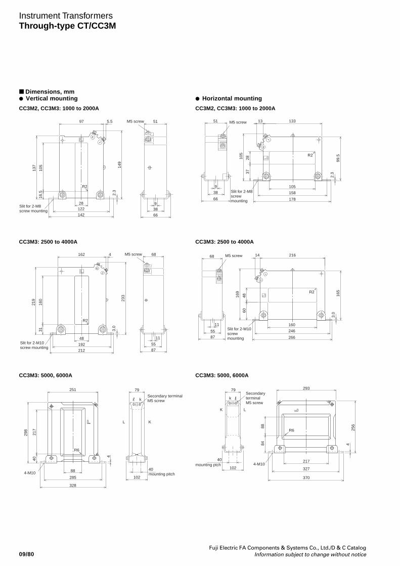
09/80Fuji Electric FA Components & Systems Co., Ltd./D & C Catalog
Information subject to change without notice
Instrument TransformersThrough-type CT/CC3M
Dimensions, mm Vertical mounting
CC3M2, CC3M3: 1000 to 2000A CC3M2, CC3M3: 1000 to 2000A
97
R2
Slit for 2-M8 screw mounting
137
105 14
9
16.5 2.3
5.5 51
66
38
28
142
122
K
M5 screw
9
51
66
38
9
13
R2
133
105
158
178
M5 screw
99.5
2.337
28105
Slit for 2-M8 screw mounting
K
CC3M3: 2500 to 4000A CC3M3: 2500 to 4000A
CC3M3: 5000, 6000A CC3M3: 5000, 6000A
162 4
R2
Slit for 2-M10 screw mounting
219
160
31
233
3.0
68
87
5548
212
192
K
M5 screw
11
68
8755
11
14
R2
216
160
246
266
M5 screw
165
3.060
48169
Slit for 2-M10 screw mounting
K
251
328
88
102285
R6
298
217
40
4
4-M1040 mounting pitch
L K
79
kSecondary terminal M5 screw
102
40
K L
79
kSecondary terminal M5 screw
mounting ptch327
217
370
293
R6
4-M10
8884 4
256
Horizontal mounting
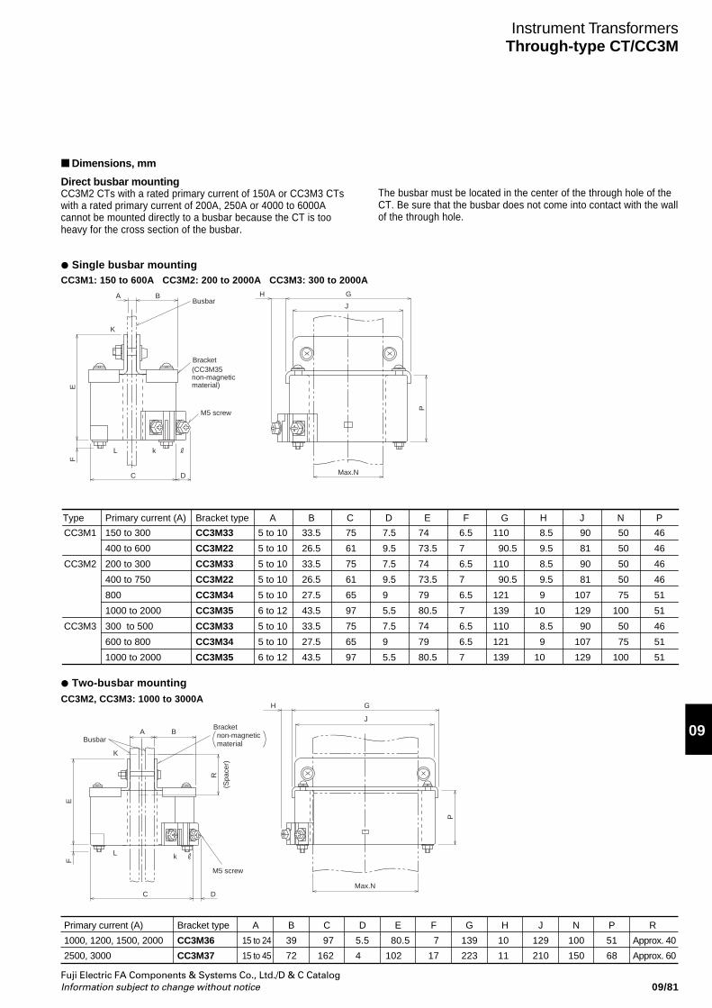
Fuji Electric FA Components & Systems Co., Ltd./D & C CatalogInformation subject to change without notice
09
09/81
Instrument TransformersThrough-type CT/CC3M
Dimensions, mm
Direct busbar mountingCC3M2 CTs with a rated primary current of 150A or CC3M3 CTswith a rated primary current of 200A, 250A or 4000 to 6000Acannot be mounted directly to a busbar because the CT is tooheavy for the cross section of the busbar.
Single busbar mountingCC3M1: 150 to 600A CC3M2: 200 to 2000A CC3M3: 300 to 2000A
A H G
P
J
L
C D
EF
k
K
BBusbar
Bracket(CC3M35 non-magnetic material)
M5 screw
Max.N
Two-busbar mountingCC3M2, CC3M3: 1000 to 3000A
A
H G
P
J
L
C D
E
R
(Spa
cer)
F
k
K
BBusbar
Bracketnon-magnetic material
M5 screw
Max.N
B C D E F G H J N PA
5 to 10
5 to 10
5 to 10
5 to 10
5 to 10
6 to 12
5 to 10
5 to 10
6 to 12
33.5
26.5
33.5
26.5
27.5
43.5
33.5
27.5
43.5
75
61
75
61
65
97
75
65
97
7.5
9.5
7.5
9.5
9
5.5
7.5
9
5.5
74
73.5
74
73.5
79
80.5
74
79
80.5
6.5
7
6.5
7
6.5
7
6.5
6.5
7
110
90.5
110
90.5
121
139
110
121
139
8.5
9.5
8.5
9.5
9
10
8.5
9
10
90
81
90
81
107
129
90
107
129
50
50
50
50
75
100
50
75
100
46
46
46
46
51
51
46
51
51
Primary current (A)
150 to 300
400 to 600
200 to 300
400 to 750
800
1000 to 2000
300 to 500
600 to 800
1000 to 2000
Bracket type
CC3M33
CC3M22
CC3M33
CC3M22
CC3M34
CC3M35
CC3M33
CC3M34
CC3M35
Type
CC3M1
CC3M2
CC3M3
Primary current (A)
1000, 1200, 1500, 2000
2500, 3000
Bracket type
CC3M36
CC3M37
A B C D E F G H J N P R
15 to 24 39 97 5.5 80.5 7 139 10 129 100 51 Approx. 40
15 to 45 72 162 4 102 17 223 11 210 150 68 Approx. 60
The busbar must be located in the center of the through hole of theCT. Be sure that the busbar does not come into contact with the wallof the through hole.
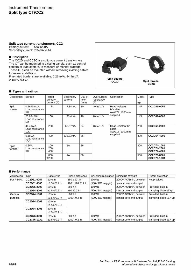
09/82Fuji Electric FA Components & Systems Co., Ltd./D & C Catalog
Information subject to change without notice
Instrument TransformersSplit type CT/CC2
Split type current transformers, CC2Primary current: 5 to 1200ASecondary current: 7.34mA to 1A
DescriptionThe CC2D and CC2C are split-type current transformers.The CT can be mounted to existing panels, such as controlcenters or load centers, to measure or monitor wattage.These CTs can be mounted without removing existing cablesfor easier installation.Five rated burdens are available: 0.26mVA, 44.4mVA,0.18VA, 0.5VA
Ratedprimarycurrent (A)
5
50
200
400
100 200 400
8001200
Burden
0.2693mVALoad resistance5Ω
26.93mVALoad resistance5Ω
44.4mVALoad resistance10Ω
0.18VALoad resistance10Ω
0.5VALoad resistance5Ω
Type
CC2D81-0057
CC2D81-0506
CC2D65-2008
CC2D54-4009
CC2D74-1001CC2D74-2001CC2D74-4001
CC2C76-8001CC2C76-12X1
Secondarycurrent
7.34mA
73.4mA
66.67mA
133.33mA
1A
1A
Dia. ofhole(mm)
10
10
24
36
36
60
Overcurrentresistance(A)
40 In/1.0s
10 In/1.0s
40 In/1.0s
Description
Splitsquare
Splittoroidal
Connection
Heat-resistantIV cableAWG22 1000mmsupplied
Heat-resistant IVcableAWG18 1000mmsupplied
Mass
(g)
45
45
200
300
300
500
Split squareCC2D
Types and ratings
Split toroidalCC2C
Performance
TypeCC2D81-0057CC2D81-0506CC2D65-2008CC2D54-4009CC2D74-1001
CC2D74-2001
CC2D74-4001
CC2C76-8001CC2C76-12X1
ApplicationFor F-MPC
Generalpurpose
Ratio error±1% In±1.5%/0.2 In±1% In±1.5%/0.2 In±1% In±1.5%/0.2 In±1% In±1.5%/0.2 In±1% In±1.5%/0.2 In±1% In±1.5%/0.2 In
Phase difference150' ±90' /In180' ±120' /0.2 In±60' /In±90' /0.2 In±80' /In ±100' /0.2 In
±80' /In ±100' /0.2 In
Insulation resistance100MΩ
(500V DC megger)100MΩ
(500V DC megger)100MΩ
(500V DC megger)
100MΩ
(500V DC megger)
Output protectionNot provided
Provided, built-in clamping diode ±3VpProvided, built-in clamping diode ±1.4Vp
Provided, built-in clamping diode ±1.4Vp
Dielectric strength2000V AC/1min, between sensor core and output2000V AC/1min, between sensor core and output2000V AC/1min, between sensor core and output
2000V AC/1min, between sensor core and output
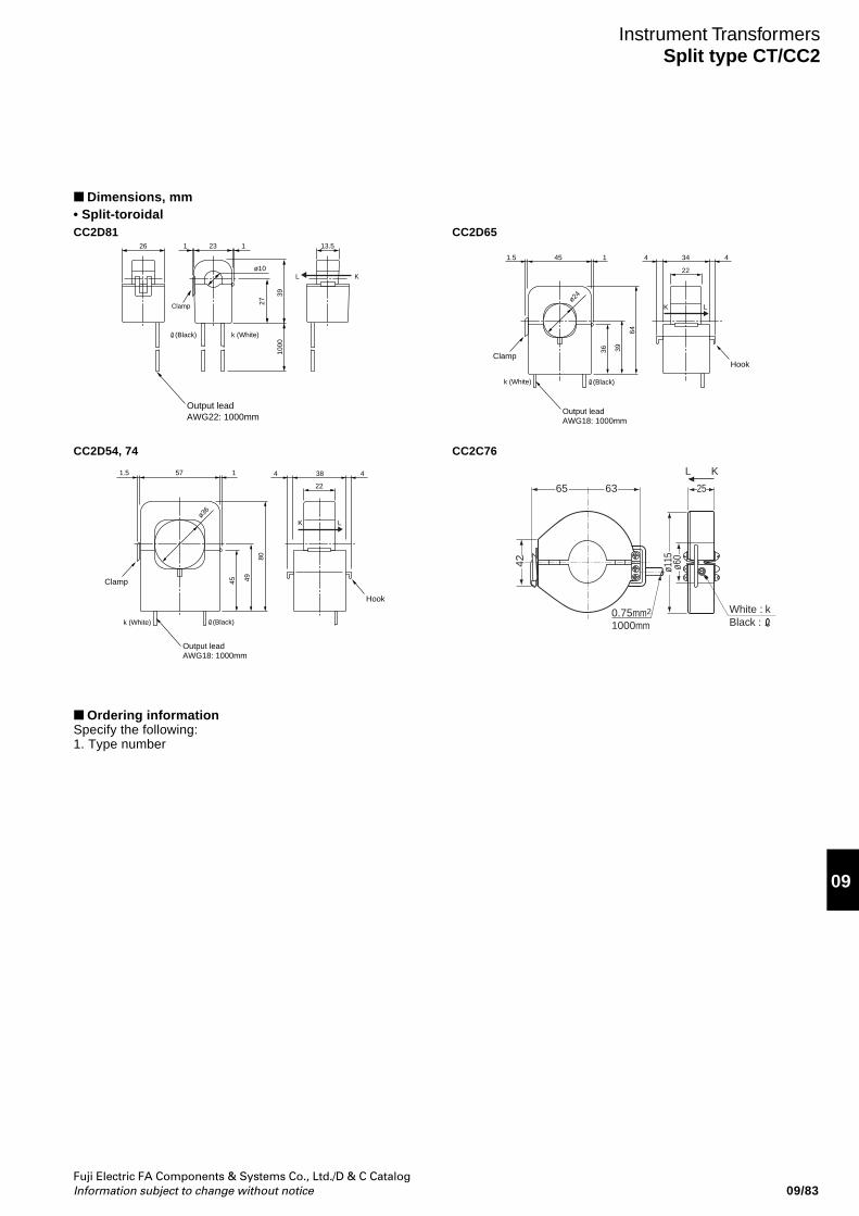
Fuji Electric FA Components & Systems Co., Ltd./D & C CatalogInformation subject to change without notice
09
09/83
Dimensions, mm• Split-toroidal
Instrument TransformersSplit type CT/CC2
CC2C76
L K
White : kBlack :
65 63
0.75mm2
1000mm
25
42 ø115
ø60
CC2D81
CC2D54, 74
CC2D651 126 23 13.5
27
3910
00
ø10L K
(Black) k (White)
Output leadAWG22: 1000mm
Clamp
(Black)k (White)
451.5 1 4 34 4
22
36 39
64
K Lø24
Output leadAWG18: 1000mm
HookClamp
(Black)k (White)
ø36
Output leadAWG18: 1000mm
Hook
Clamp
1.5 57 1 4 38 4
22
45 49
80
K L
Ordering informationSpecify the following:1. Type number
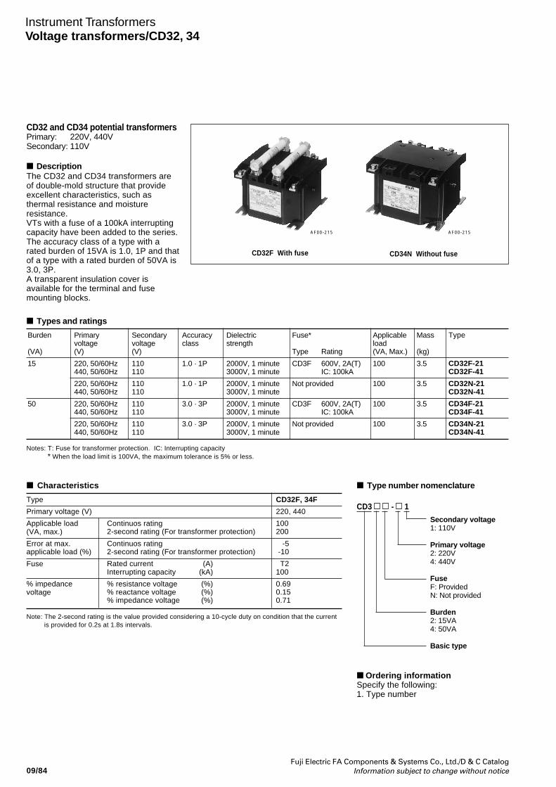
09/84Fuji Electric FA Components & Systems Co., Ltd./D & C Catalog
Information subject to change without notice
CD32 and CD34 potential transformersPrimary: 220V, 440VSecondary: 110V
DescriptionThe CD32 and CD34 transformers areof double-mold structure that provideexcellent characteristics, such asthermal resistance and moistureresistance.VTs with a fuse of a 100kA interruptingcapacity have been added to the series.The accuracy class of a type with arated burden of 15VA is 1.0, 1P and thatof a type with a rated burden of 50VA is3.0, 3P.A transparent insulation cover isavailable for the terminal and fusemounting blocks.
Types and ratings
Secondaryvoltage(V)
110110
110110
110110
110110
Primaryvoltage(V)
220, 50/60Hz440, 50/60Hz
220, 50/60Hz440, 50/60Hz
220, 50/60Hz440, 50/60Hz
220, 50/60Hz440, 50/60Hz
Type
CD32F-21CD32F-41
CD32N-21CD32N-41
CD34F-21CD34F-41
CD34N-21CD34N-41
Accuracyclass
1.0 · 1P
1.0 · 1P
3.0 · 3P
3.0 · 3P
Dielectricstrength
2000V, 1 minute3000V, 1 minute
2000V, 1 minute3000V, 1 minute
2000V, 1 minute3000V, 1 minute
2000V, 1 minute3000V, 1 minute
Fuse*
Type Rating
CD3F 600V, 2A(T)IC: 100kA
Not provided
CD3F 600V, 2A(T)IC: 100kA
Not provided
Burden
(VA)
15
50
Notes: T: Fuse for transformer protection. IC: Interrupting capacity* When the load limit is 100VA, the maximum tolerance is 5% or less.
Applicableload(VA, Max.)
100
100
100
100
Mass
(kg)
3.5
3.5
3.5
3.5
CD32F With fuse CD34N Without fuse
AF00-215AF00-215
Note: The 2-second rating is the value provided considering a 10-cycle duty on condition that the currentis provided for 0.2s at 1.8s intervals.
Type
Primary voltage (V)
Applicable load(VA, max.)
Error at max.applicable load (%)
Fuse
% impedancevoltage
Characteristics
Continuos rating2-second rating (For transformer protection)
Continuos rating2-second rating (For transformer protection)
Rated current (A)Interrupting capacity (kA)
% resistance voltage (%)% reactance voltage (%)% impedance voltage (%)
CD32F, 34F
220, 440
100200
-5 -10
T2100
0.690.150.71
CD3 - 1
Secondary voltage1: 110V
Primary voltage2: 220V4: 440V
FuseF: ProvidedN: Not provided
Burden2: 15VA4: 50VA
Basic type
Type number nomenclature
Ordering informationSpecify the following:1. Type number
Instrument TransformersVoltage transformers/CD32, 34
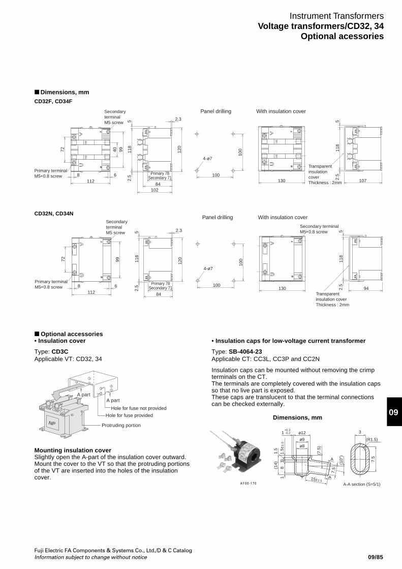
Fuji Electric FA Components & Systems Co., Ltd./D & C CatalogInformation subject to change without notice
09
09/85
Dimensions, mmCD32F, CD34F
Instrument TransformersVoltage transformers/CD32, 34
Optional acessories
FUSE
FUSE
FUSE
FUSE
Secondary terminal M5 screw
1128 6
130 107
Transparent insulation cover Thickness : 2mm
10284
Primary 78Secondary 71
99
52.
5
120
100
4-ø7
Panel drilling With insulation cover
10072 11
8
402.3 5
2.5
118
Primary terminal M5×0.8 screw
CD32N, CD34N
Primary terminal M5×0.8 screw
1128 6 130 94
84
99
52.
5
120
100
4-ø7
100
Secondary terminal M5×0.8 screw
Transparent insulation cover Thickness : 2mm
72 118
2.3 52.
511
8
Secondary terminal M5 screw
Panel drilling With insulation cover
Primary 78Secondary 71
Optional accessories• Insulation cover
Type: CD3CApplicable VT: CD32, 34
A partA part
NP Protruding portion
Hole for fuse not provided
Hole for fuse provided
• Insulation caps for low-voltage current transformer
Type: SB-4064-23Applicable CT: CC3L, CC3P and CC2N
Insulation caps can be mounted without removing the crimpterminals on the CT.The terminals are completely covered with the insulation capsso that no live part is exposed.These caps are translucent to that the terminal connectionscan be checked externally.
Dimensions, mm
ø8
A
A
3
A-A section (S=5/1)
(R1.5)
15±1.5
8
7.5
(7.5
)
(10°
)
7.5(1
4)1.
5
111
1.5±
1.0
ø9
ø121 -0.2+0.3
Mounting insulation coverSlightly open the A-part of the insulation cover outward.Mount the cover to the VT so that the protruding portionsof the VT are inserted into the holes of the insulationcover.
AF00-170
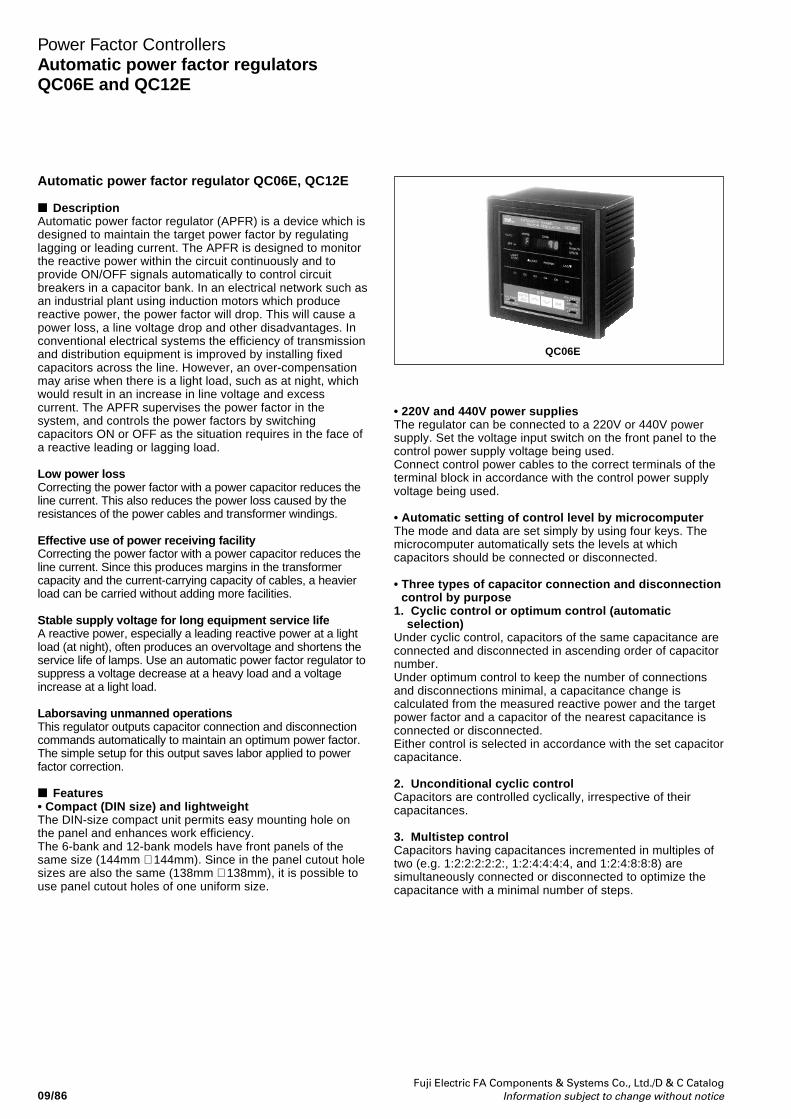
Fuji Electric FA Components & Systems Co., Ltd./D & C CatalogInformation subject to change without notice09/86
Power Factor ControllersAutomatic power factor regulatorsQC06E and QC12E
Automatic power factor regulator QC06E, QC12E
DescriptionAutomatic power factor regulator (APFR) is a device which isdesigned to maintain the target power factor by regulatinglagging or leading current. The APFR is designed to monitorthe reactive power within the circuit continuously and toprovide ON/OFF signals automatically to control circuitbreakers in a capacitor bank. In an electrical network such asan industrial plant using induction motors which producereactive power, the power factor will drop. This will cause apower loss, a line voltage drop and other disadvantages. Inconventional electrical systems the efficiency of transmissionand distribution equipment is improved by installing fixedcapacitors across the line. However, an over-compensationmay arise when there is a light load, such as at night, whichwould result in an increase in line voltage and excesscurrent. The APFR supervises the power factor in thesystem, and controls the power factors by switchingcapacitors ON or OFF as the situation requires in the face ofa reactive leading or lagging load.
Low power lossCorrecting the power factor with a power capacitor reduces theline current. This also reduces the power loss caused by theresistances of the power cables and transformer windings.
Effective use of power receiving facilityCorrecting the power factor with a power capacitor reduces theline current. Since this produces margins in the transformercapacity and the current-carrying capacity of cables, a heavierload can be carried without adding more facilities.
Stable supply voltage for long equipment service lifeA reactive power, especially a leading reactive power at a lightload (at night), often produces an overvoltage and shortens theservice life of lamps. Use an automatic power factor regulator tosuppress a voltage decrease at a heavy load and a voltageincrease at a light load.
Laborsaving unmanned operationsThis regulator outputs capacitor connection and disconnectioncommands automatically to maintain an optimum power factor.The simple setup for this output saves labor applied to powerfactor correction.
Features• Compact (DIN size) and lightweightThe DIN-size compact unit permits easy mounting hole onthe panel and enhances work efficiency.The 6-bank and 12-bank models have front panels of thesame size (144mm × 144mm). Since in the panel cutout holesizes are also the same (138mm × 138mm), it is possible touse panel cutout holes of one uniform size.
• 220V and 440V power suppliesThe regulator can be connected to a 220V or 440V powersupply. Set the voltage input switch on the front panel to thecontrol power supply voltage being used.Connect control power cables to the correct terminals of theterminal block in accordance with the control power supplyvoltage being used.
• Automatic setting of control level by microcomputerThe mode and data are set simply by using four keys. Themicrocomputer automatically sets the levels at whichcapacitors should be connected or disconnected.
• Three types of capacitor connection and disconnectioncontrol by purpose
1. Cyclic control or optimum control (automaticselection)
Under cyclic control, capacitors of the same capacitance areconnected and disconnected in ascending order of capacitornumber.Under optimum control to keep the number of connectionsand disconnections minimal, a capacitance change iscalculated from the measured reactive power and the targetpower factor and a capacitor of the nearest capacitance isconnected or disconnected.Either control is selected in accordance with the set capacitorcapacitance.
2. Unconditional cyclic controlCapacitors are controlled cyclically, irrespective of theircapacitances.
3. Multistep controlCapacitors having capacitances incremented in multiples oftwo (e.g. 1:2:2:2:2:2:, 1:2:4:4:4:4, and 1:2:4:8:8:8) aresimultaneously connected or disconnected to optimize thecapacitance with a minimal number of steps.
QC06E
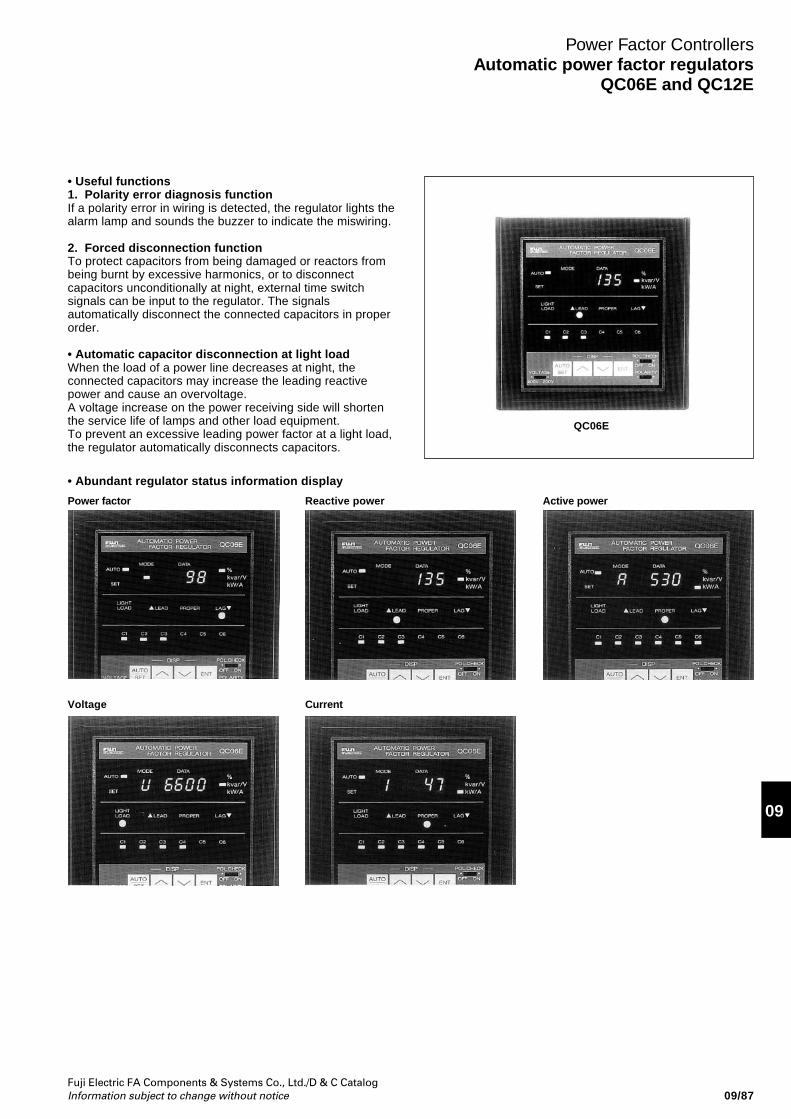
Fuji Electric FA Components & Systems Co., Ltd./D & C CatalogInformation subject to change without notice
09
09/87
Power Factor ControllersAutomatic power factor regulators
QC06E and QC12E
• Useful functions1. Polarity error diagnosis functionIf a polarity error in wiring is detected, the regulator lights thealarm lamp and sounds the buzzer to indicate the miswiring.
2. Forced disconnection functionTo protect capacitors from being damaged or reactors frombeing burnt by excessive harmonics, or to disconnectcapacitors unconditionally at night, external time switchsignals can be input to the regulator. The signalsautomatically disconnect the connected capacitors in properorder.
• Automatic capacitor disconnection at light loadWhen the load of a power line decreases at night, theconnected capacitors may increase the leading reactivepower and cause an overvoltage.A voltage increase on the power receiving side will shortenthe service life of lamps and other load equipment.To prevent an excessive leading power factor at a light load,the regulator automatically disconnects capacitors.
QC06E
• Abundant regulator status information display
Power factor
Voltage
Reactive power
Current
Active power
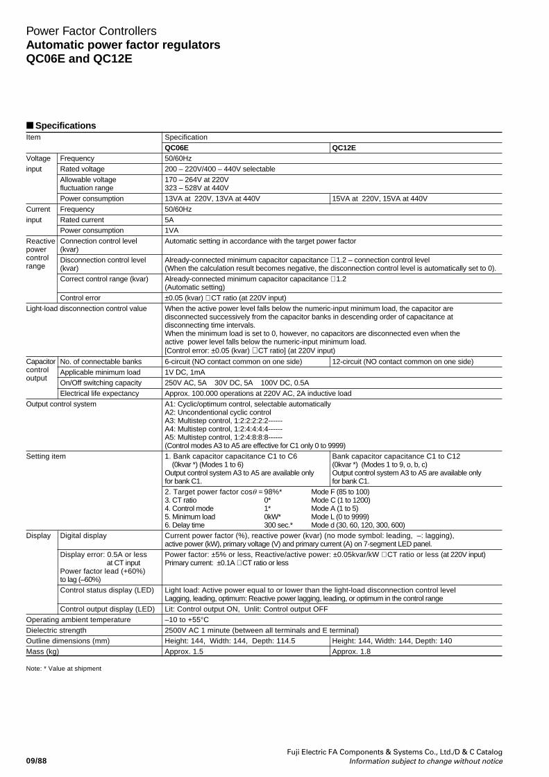
Fuji Electric FA Components & Systems Co., Ltd./D & C CatalogInformation subject to change without notice09/88
Power Factor ControllersAutomatic power factor regulatorsQC06E and QC12E
SpecificationsItem Specification
QC06E QC12EVoltage Frequency 50/60Hzinput Rated voltage 200 – 220V/400 – 440V selectable
Allowable voltage 170 – 264V at 220Vfluctuation range 323 – 528V at 440VPower consumption 13VA at 220V, 13VA at 440V 15VA at 220V, 15VA at 440V
Current Frequency 50/60Hzinput Rated current 5A
Power consumption 1VAConnection control level Automatic setting in accordance with the target power factor(kvar)Disconnection control level Already-connected minimum capacitor capacitance × 1.2 – connection control level(kvar) (When the calculation result becomes negative, the disconnection control level is automatically set to 0).Correct control range (kvar) Already-connected minimum capacitor capacitance × 1.2
(Automatic setting)Control error ±0.05 (kvar) × CT ratio (at 220V input)
Light-load disconnection control value When the active power level falls below the numeric-input minimum load, the capacitor aredisconnected successively from the capacitor banks in descending order of capacitance atdisconnecting time intervals.When the minimum load is set to 0, however, no capacitors are disconnected even when theactive power level falls below the numeric-input minimum load.[Control error: ±0.05 (kvar) × CT ratio] (at 220V input)
No. of connectable banks 6-circuit (NO contact common on one side) 12-circuit (NO contact common on one side)Applicable minimum load 1V DC, 1mAOn/Off switching capacity 250V AC, 5A 30V DC, 5A 100V DC, 0.5AElectrical life expectancy Approx. 100.000 operations at 220V AC, 2A inductive load
Output control system A1: Cyclic/optimum control, selectable automaticallyA2: Uncondentional cyclic controlA3: Multistep control, 1:2:2:2:2:2------A4: Multistep control, 1:2:4:4:4:4------A5: Multistep control, 1:2:4:8:8:8------(Control modes A3 to A5 are effective for C1 only 0 to 9999)
Setting item 1. Bank capacitor capacitance C1 to C6 Bank capacitor capacitance C1 to C12 (0kvar *) (Modes 1 to 6) (0kvar *) (Modes 1 to 9, o, b, c)Output control system A3 to A5 are available only Output control system A3 to A5 are available onlyfor bank C1. for bank C1.2. Target power factor cosθ = 98%* Mode F (85 to 100)3. CT ratio 0* Mode C (1 to 1200)4. Control mode 1* Mode A (1 to 5)5. Minimum load 0kW* Mode L (0 to 9999)6. Delay time 300 sec.* Mode d (30, 60, 120, 300, 600)
Display Digital display Current power factor (%), reactive power (kvar) (no mode symbol: leading, –: lagging),active power (kW), primary voltage (V) and primary current (A) on 7-segment LED panel.
Display error: 0.5A or less Power factor: ±5% or less, Reactive/active power: ±0.05kvar/kW × CT ratio or less (at 220V input) at CT input Primary current: ±0.1A × CT ratio or lessPower factor lead (+60%)to lag (–60%)Control status display (LED) Light load: Active power equal to or lower than the light-load disconnection control level
Lagging, leading, optimum: Reactive power lagging, leading, or optimum in the control rangeControl output display (LED) Lit: Control output ON, Unlit: Control output OFF
Operating ambient temperature –10 to +55°CDielectric strength 2500V AC 1 minute (between all terminals and E terminal)Outline dimensions (mm) Height: 144, Width: 144, Depth: 114.5 Height: 144, Width: 144, Depth: 140Mass (kg) Approx. 1.5 Approx. 1.8
Capacitorcontroloutput
Reactivepowercontrolrange
Note: * Value at shipment
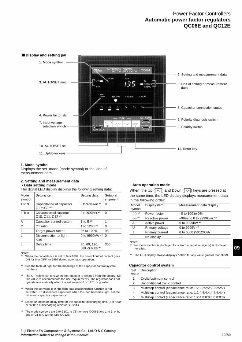
Fuji Electric FA Components & Systems Co., Ltd./D & C CatalogInformation subject to change without notice
09
09/89
Power Factor ControllersAutomatic power factor regulators
QC06E and QC12E
Display and setting panel
2. Setting and measurement data
1. Mode symbolDisplays the set mode (mode symbol) or the kind ofmeasurement data.
2. Setting and measurement data • Data setting modeThe digital LED display displays the following setting data:
Mode Setting item Setting data Setup atsymbol shipment
1 to 9 Capacitance of capacitor 0 to 9999kvar *1 0C1 to C9 *6
o, b, c Capacitance of capacitor 0 to 9999kvar *1 0C10, C11, C12 *6
A Capacitor control system 1 to 5 *2 1C CT ratio 1 to 1200 *3 0F Target power factor 85 to 100% 98L Disconnection at light 0 to 9999kW *4 0
loadd Delay time 30, 60, 120, 300
300, or 600s *5
Notes:*1 When the capacitance is set to 0 or 9999, the control output contact goes
ON for 0 or OFF for 9999 during automatic operation.
*2 See the table at right for the meanings of the capacitor control systemnumbers.
*3 The CT ratio is set to 0 when the regulator is shipped from the factory. Setthis value to accommodate the use requirements. The regulator does notoperate automatically when the set value is 0 or 1201 or greater.
*4 When the set value is 0, the light-load disconnection function is notactivated. To disconnect capacitors when the load becomes light, set theminimum capacitor capacitance.
*5 Select an optimum delay time for the capacitor discharging unit. (Set “300”or “600” if a discharging resistor is used.)
*6 The mode symbols are 1 to 6 (C1 to C6) for type QC06E and 1 to 9, o, b,and c (C1 to C12) for type QC12E.
1. Mode symbol
3. AUTO/SET mode
4. Power factor status
7. Input voltageselection switch
10. AUTO/SET select key
11. Up/down keys
5. Unit of setting or measurementdata
6. Capacitor connection status
8. Polarity diagnosis switch
9. Polarity switch
12. Enter key
• Auto operation mode
When the Up ( ) and Down ( ) keys are pressed atthe same time, the LED display displays measurement datain the following order:Model Display item Measurement data displaysymbol
(–) *7 Power factor –0 to 100 to 0% (–) *7 Reactive power –9999 to 0 to 9999kvar *8
A Active power 0 to 9999kW *8
U Primary voltage 0 to 9999V *8
I Primary current 0 to 6000 (5X1200)ANo display —
Notes:*7 No mode symbol is displayed for a lead; a negative sign (–) is displayed
for a lag.
*8 The LED display always displays “9999” for any value greater than 9999.
Capacitor control system Set Description value
1 Cyclic/optimum control 2 Unconditional cyclic control 3 Multistep control (capacitance ratio: 1:2:2:2:2:2:2:2:2:2:2) 4 Multistep control (capacitance ratio: 1:2:4:4:4:4:4:4:4:4:4) 5 Multistep control (capacitance ratio: 1:2:4:8:8:8:8:8:8:8:8)
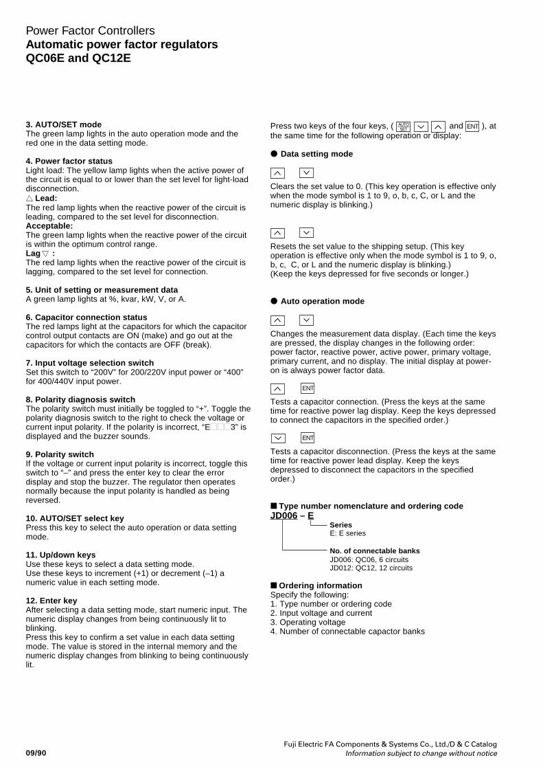
Fuji Electric FA Components & Systems Co., Ltd./D & C CatalogInformation subject to change without notice09/90
Power Factor ControllersAutomatic power factor regulatorsQC06E and QC12E
3. AUTO/SET modeThe green lamp lights in the auto operation mode and thered one in the data setting mode.
4. Power factor statusLight load: The yellow lamp lights when the active power ofthe circuit is equal to or lower than the set level for light-loaddisconnection. Lead:The red lamp lights when the reactive power of the circuit isleading, compared to the set level for disconnection.Acceptable:The green lamp lights when the reactive power of the circuitis within the optimum control range.Lag :The red lamp lights when the reactive power of the circuit islagging, compared to the set level for connection.
5. Unit of setting or measurement dataA green lamp lights at %, kvar, kW, V, or A.
6. Capacitor connection statusThe red lamps light at the capacitors for which the capacitorcontrol output contacts are ON (make) and go out at thecapacitors for which the contacts are OFF (break).
7. Input voltage selection switchSet this switch to “200V” for 200/220V input power or “400”for 400/440V input power.
8. Polarity diagnosis switchThe polarity switch must initially be toggled to “+”. Toggle thepolarity diagnosis switch to the right to check the voltage orcurrent input polarity. If the polarity is incorrect, “E 3” isdisplayed and the buzzer sounds.
9. Polarity switchIf the voltage or current input polarity is incorrect, toggle thisswitch to “–” and press the enter key to clear the errordisplay and stop the buzzer. The regulator then operatesnormally because the input polarity is handled as beingreversed.
10. AUTO/SET select keyPress this key to select the auto operation or data settingmode.
11. Up/down keysUse these keys to select a data setting mode.Use these keys to increment (+1) or decrement (–1) anumeric value in each setting mode.
12. Enter keyAfter selecting a data setting mode, start numeric input. Thenumeric display changes from being continuously lit toblinking.Press this key to confirm a set value in each data settingmode. The value is stored in the internal memory and thenumeric display changes from blinking to being continuouslylit.
Press two keys of the four keys, ( AUTOSET and ENT ), at
the same time for the following operation or display:
Data setting mode
Clears the set value to 0. (This key operation is effective onlywhen the mode symbol is 1 to 9, o, b, c, C, or L and thenumeric display is blinking.)
Resets the set value to the shipping setup. (This keyoperation is effective only when the mode symbol is 1 to 9, o,b, c, C, or L and the numeric display is blinking.)(Keep the keys depressed for five seconds or longer.)
Auto operation mode
Changes the measurement data display. (Each time the keysare pressed, the display changes in the following order:power factor, reactive power, active power, primary voltage,primary current, and no display. The initial display at power-on is always power factor data.
ENT
Tests a capacitor connection. (Press the keys at the sametime for reactive power lag display. Keep the keys depressedto connect the capacitors in the specified order.)
ENT
Tests a capacitor disconnection. (Press the keys at the sametime for reactive power lead display. Keep the keysdepressed to disconnect the capacitors in the specifiedorder.)
Type number nomenclature and ordering codeJD006 – E
SeriesE: E series
No. of connectable banksJD006: QC06, 6 circuitsJD012: QC12, 12 circuits
Ordering informationSpecify the following:1. Type number or ordering code2. Input voltage and current3. Operating voltage4. Number of connectable capactor banks
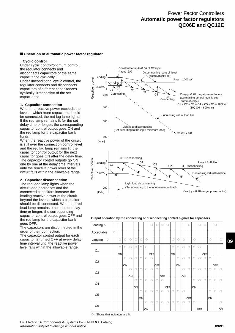
Fuji Electric FA Components & Systems Co., Ltd./D & C CatalogInformation subject to change without notice
09
09/91
Power Factor ControllersAutomatic power factor regulators
QC06E and QC12E
• Cyclic controlUnder cyclic control/optimum control,the regulator connects anddisconnects capacitors of the samecapacitance cyclically.Under unconditional cyclic control, theregulator connects and disconnectscapacitors of different capacitancescyclically, irrespective of the setcapacitance.
1. Capacitor connectionWhen the reactive power exceeds thelevel at which more capacitors shouldbe connected, the red lag lamp lights.If the red lamp remains lit for the setdelay time or longer, the correspondingcapacitor control output goes ON andthe red lamp for the capacitor banklights.When the reactive power of the circuitis still over the connection control leveland the red lag lamp remains lit, thecapacitor control output for the nextcapacitor goes ON after the delay time.The capacitor control outputs go ONone by one at the delay time intervalsuntil the reactive power level of thecircuit falls within the allowable range.
2. Capacitor disconnectionThe red lead lamp lights when thecircuit load decreases and theconnected capacitors increase theleading reactive power of the circuitbeyond the level at which a capacitorshould be disconnected. When the redlead lamp remains lit for the set delaytime or longer, the correspondingcapacitor control output goes OFF andthe red lamp for the capacitor bankgoes OFF.The capacitors are disconnected in theorder of their connection.The capacitor control output for eachcapacitor is turned OFF at every delaytime interval until the reactive powerlevel falls within the allowable range.
Operation of automatic power factor regulator
Constant for up to 0.5A of CT input(rating:5A) Disconnecting control level
(automatically set)P = 1000kW
P = 1000kW
Cos = 0.98 ( target power factor)(Connecting control level is set automatically.) C1 = C2 = C3 = C4 = C5 = C6 = 100kvar
(100 × 6 = 600kvar)
C1
C1
C2
C2
C3
C3
C4
C4
C5
C5
C6
C6
Connecting
Connecting
lncreasing virtual load line
Cos = 0.8
Cos = 0.98 (target power factor)
Light load disconnecting
Light load disconnecting
(Set according to the input minimum load)
(Set according to the input minimum load)
0
0
200
200
400
600
800
Lagging
Leading
Rea
ctiv
e p
ower
Rea
ctiv
e p
ower
Disconnecting
Disconnecting
Decreasing virtual load line
max
max
1
0
[kvar]
[kvar]
1
θ
θ
θ
Lagging
Leading
Output operation by the connecting or disconnecting control signals for capacitors
C1
C2
C3
C4
C5
C6ON
OFF
ON
OFF
ON
OFF
OFF
ON
ON
ON
ON
OFF
OFF
OFF
OFF
ON
ON
ON
ON
ON
Leading
Acceptable
Lagging
: Shows that indicators are lit.
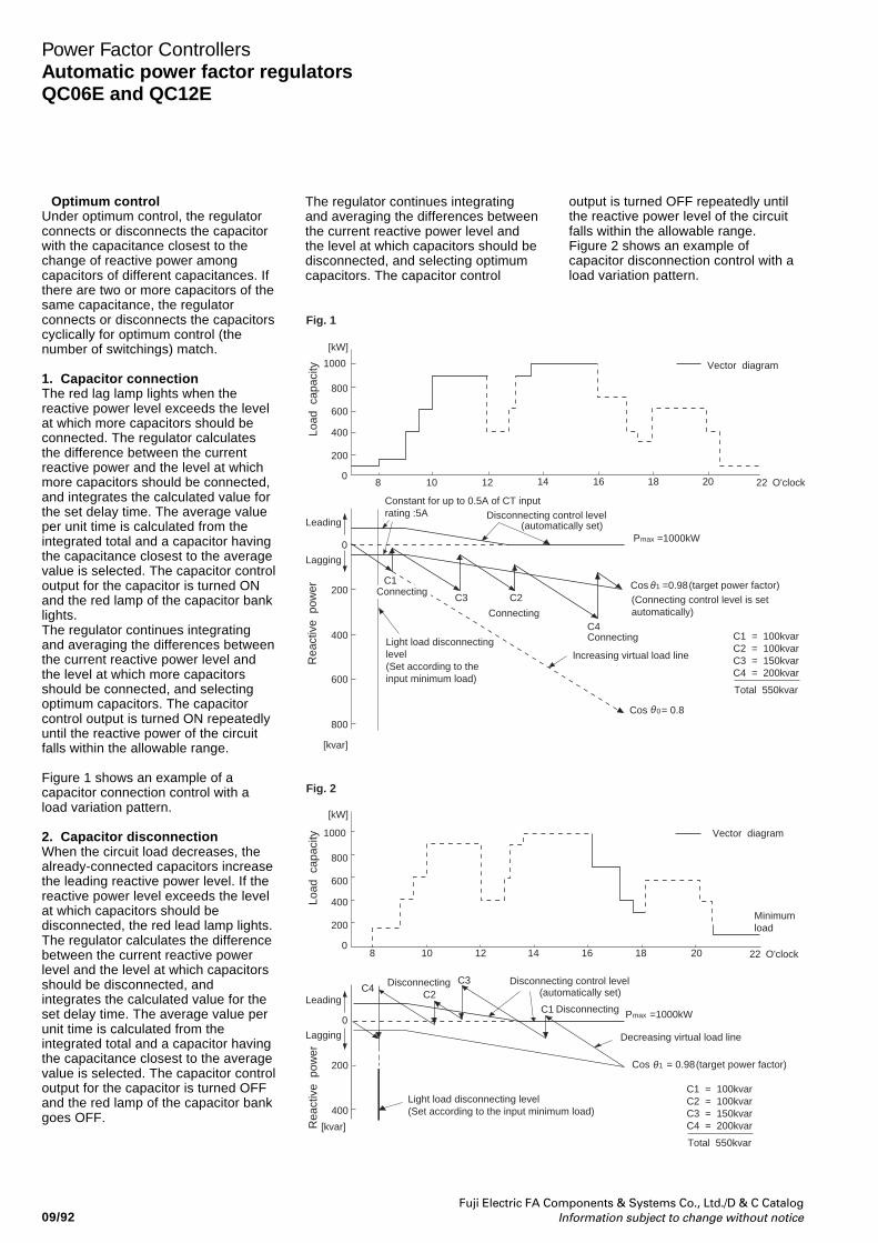
Fuji Electric FA Components & Systems Co., Ltd./D & C CatalogInformation subject to change without notice09/92
Power Factor ControllersAutomatic power factor regulatorsQC06E and QC12E
• Optimum controlUnder optimum control, the regulatorconnects or disconnects the capacitorwith the capacitance closest to thechange of reactive power amongcapacitors of different capacitances. Ifthere are two or more capacitors of thesame capacitance, the regulatorconnects or disconnects the capacitorscyclically for optimum control (thenumber of switchings) match.
1. Capacitor connectionThe red lag lamp lights when thereactive power level exceeds the levelat which more capacitors should beconnected. The regulator calculatesthe difference between the currentreactive power and the level at whichmore capacitors should be connected,and integrates the calculated value forthe set delay time. The average valueper unit time is calculated from theintegrated total and a capacitor havingthe capacitance closest to the averagevalue is selected. The capacitor controloutput for the capacitor is turned ONand the red lamp of the capacitor banklights.The regulator continues integratingand averaging the differences betweenthe current reactive power level andthe level at which more capacitorsshould be connected, and selectingoptimum capacitors. The capacitorcontrol output is turned ON repeatedlyuntil the reactive power of the circuitfalls within the allowable range.
Figure 1 shows an example of acapacitor connection control with aload variation pattern.
2. Capacitor disconnectionWhen the circuit load decreases, thealready-connected capacitors increasethe leading reactive power level. If thereactive power level exceeds the levelat which capacitors should bedisconnected, the red lead lamp lights.The regulator calculates the differencebetween the current reactive powerlevel and the level at which capacitorsshould be disconnected, andintegrates the calculated value for theset delay time. The average value perunit time is calculated from theintegrated total and a capacitor havingthe capacitance closest to the averagevalue is selected. The capacitor controloutput for the capacitor is turned OFFand the red lamp of the capacitor bankgoes OFF.
The regulator continues integratingand averaging the differences betweenthe current reactive power level andthe level at which capacitors should bedisconnected, and selecting optimumcapacitors. The capacitor control
1000
800
600
400
200
08 10 12 14 16 18 20 22 O'clock
8 10 12 14 16 18 20 22 O'clock
Vector diagram
Vector diagram
Load
cap
acity
1000
800
600
400
200
0
Load
cap
acity
0
200
400
600
800
Leading
0
200
400
Constant for up to 0.5A of CT inputrating :5A Disconnecting control level
Disconnecting Disconnecting control level
Decreasing virtual load line
(automatically set)
(automatically set)
P =1000kW
Cos =0.98(target power factor)
Cos = 0.98(target power factor)
(Connecting control level is setautomatically)
C1
Connecting
Connecting
C3 C2
C3
C1
C2
C4
C4
lncreasing virtual load lineLight load disconnectinglevel (Set according to theinput minimum load)
Light load disconnecting level (Set according to the input minimum load)
Cos = 0.8
C1 = 100kvarC2 = 100kvarC3 = 150kvarC4 = 200kvar
Total 550kvar
C1 = 100kvarC2 = 100kvarC3 = 150kvarC4 = 200kvar
Total 550kvar
max
P =1000kW
1
0
[kW]
[kvar]
θ
1
Minimumload
Rea
ctiv
e p
ower
Rea
ctiv
e p
ower
Fig. 2
Fig. 1
Connecting
Lagging
max
θ
θ
[kW]
[kvar]
Leading
Lagging
Disconnecting
output is turned OFF repeatedly untilthe reactive power level of the circuitfalls within the allowable range.Figure 2 shows an example ofcapacitor disconnection control with aload variation pattern.
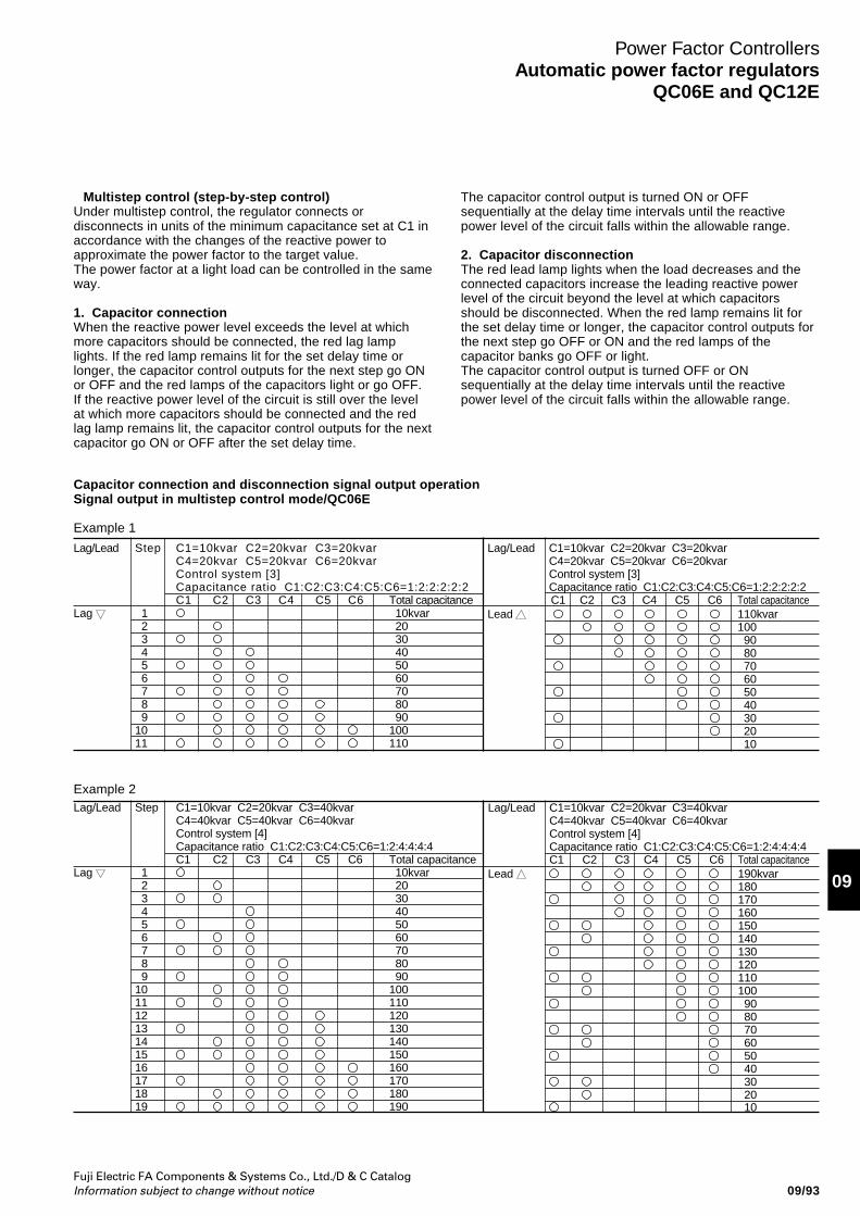
Fuji Electric FA Components & Systems Co., Ltd./D & C CatalogInformation subject to change without notice
09
09/93
Power Factor ControllersAutomatic power factor regulators
QC06E and QC12E
• Multistep control (step-by-step control)Under multistep control, the regulator connects ordisconnects in units of the minimum capacitance set at C1 inaccordance with the changes of the reactive power toapproximate the power factor to the target value.The power factor at a light load can be controlled in the sameway.
1. Capacitor connectionWhen the reactive power level exceeds the level at whichmore capacitors should be connected, the red lag lamplights. If the red lamp remains lit for the set delay time orlonger, the capacitor control outputs for the next step go ONor OFF and the red lamps of the capacitors light or go OFF.If the reactive power level of the circuit is still over the levelat which more capacitors should be connected and the redlag lamp remains lit, the capacitor control outputs for the nextcapacitor go ON or OFF after the set delay time.
The capacitor control output is turned ON or OFFsequentially at the delay time intervals until the reactivepower level of the circuit falls within the allowable range.
2. Capacitor disconnectionThe red lead lamp lights when the load decreases and theconnected capacitors increase the leading reactive powerlevel of the circuit beyond the level at which capacitorsshould be disconnected. When the red lamp remains lit forthe set delay time or longer, the capacitor control outputs forthe next step go OFF or ON and the red lamps of thecapacitor banks go OFF or light.The capacitor control output is turned OFF or ONsequentially at the delay time intervals until the reactivepower level of the circuit falls within the allowable range.
Capacitor connection and disconnection signal output operationSignal output in multistep control mode/QC06E
Example 1
Lag/Lead Step C1=10kvar C2=20kvar C3=20kvarC4=20kvar C5=20kvar C6=20kvarControl system [3]Capacitance ratio C1:C2:C3:C4:C5:C6=1:2:2:2:2:2C1 C2 C3 C4 C5 C6 Total capacitance
Lag 1 10kvar 2 20 3 30 4 40 5 50 6 60 7 70 8 80 9 9010 10011 110
Lag/Lead C1=10kvar C2=20kvar C3=20kvarC4=20kvar C5=20kvar C6=20kvarControl system [3]Capacitance ratio C1:C2:C3:C4:C5:C6=1:2:2:2:2:2C1 C2 C3 C4 C5 C6 Total capacitance
Lead 110kvar100 90 80 70 60 50 40 30 20 10
Lag/Lead Step C1=10kvar C2=20kvar C3=40kvarC4=40kvar C5=40kvar C6=40kvarControl system [4]Capacitance ratio C1:C2:C3:C4:C5:C6=1:2:4:4:4:4C1 C2 C3 C4 C5 C6 Total capacitance
Lag 1 10kvar 2 20 3 30 4 40 5 50 6 60 7 70 8 80 9 9010 10011 11012 12013 13014 14015 15016 16017 17018 18019 190
Example 2Lag/Lead C1=10kvar C2=20kvar C3=40kvar
C4=40kvar C5=40kvar C6=40kvarControl system [4]Capacitance ratio C1:C2:C3:C4:C5:C6=1:2:4:4:4:4C1 C2 C3 C4 C5 C6 Total capacitance
Lead 190kvar180170160150140130120110100 90 80 70 60 50 40 30 20 10
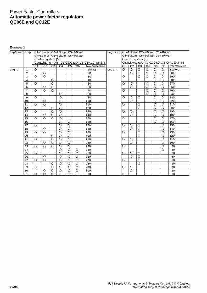
Fuji Electric FA Components & Systems Co., Ltd./D & C CatalogInformation subject to change without notice09/94
Power Factor ControllersAutomatic power factor regulatorsQC06E and QC12E
Lag/Lead Step C1=10kvar C2=20kvar C3=40kvarC4=80kvar C5=80kvar C6=80kvarControl system [5]Capacitance ratio C1:C2:C3:C4:C5:C6=1:2:4:8:8:8C1 C2 C3 C4 C5 C6 Total capacitance
Lag 1 10kvar 2 20 3 30 4 40 5 50 6 60 7 70 8 80 9 9010 10011 11012 12013 13014 14015 15016 16017 17018 18019 19020 20021 21022 22023 23024 24025 25026 26027 27028 28029 29030 30031 310
Lag/Lead C1=10kvar C2=20kvar C3=40kvarC4=80kvar C5=80kvar C6=80kvarControl system [5]Capacitance ratio C1:C2:C3:C4:C5:C6=1:2:4:8:8:8C1 C2 C3 C4 C5 C6 Total capacitance
Lead 310kvar300290280270260250240230220210200190180170160150140130120110100 90 80 70 60 50 40 30 20 10
Example 3
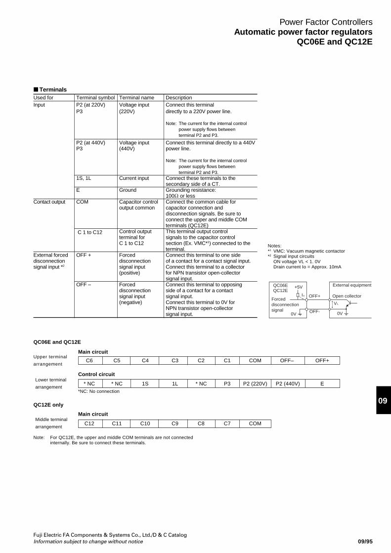
Fuji Electric FA Components & Systems Co., Ltd./D & C CatalogInformation subject to change without notice
09
09/95
Power Factor ControllersAutomatic power factor regulators
QC06E and QC12E
TerminalsUsed for Terminal symbol Terminal name DescriptionInput P2 (at 220V) Voltage input Connect this terminal
P3 (220V) directly to a 220V power line.
Note: The current for the internal controlpower supply flows betweenterminal P2 and P3.
P2 (at 440V) Voltage input Connect this terminal directly to a 440VP3 (440V) power line.
Note: The current for the internal controlpower supply flows betweenterminal P2 and P3.
1S, 1L Current input Connect these terminals to thesecondary side of a CT.
E Ground Grounding resistance:100 or less
Contact output COM Capacitor control Connect the common cable foroutput common capacitor connection and
disconnection signals. Be sure toconnect the upper and middle COMterminals (QC12E)
C 1 to C12 Control output This terminal output controlterminal for signals to the capacitor controlC 1 to C12 section (Ex. VMC*1) connected to the
terminal.External forced OFF + Forced Connect this terminal to one sidedisconnection disconnection of a contact for a contact signal input.signal input *2 signal input Connect this terminal to a collector
(positive) for NPN transistor open-collectorsignal input.
OFF – Forced Connect this terminal to opposingdisconnection side of a contact for a contactsignal input signal input.(negative) Connect this terminal to 0V for
NPN transistor open-collectorsignal input.
Notes:*1 VMC: Vacuum magnetic contactor*2 Signal input circuits
ON voltage VL < 1. 0VDrain current Io = Approx. 10mA
QC06E +5V
Forceddisconnectionsignal
External equipment
Open collectorOFF+
OFF-0V 0V
I
V
QC12Eo
L
QC06E and QC12E
Upper terminal
arrangement
Lower terminal
arrangement
QC12E only
Middle terminal
arrangement
C6 C5 C4 C3 C2 C1 COM OFF– OFF+
Main circuit
* NC * NC 1S 1L * NC P3 P2 (220V) P2 (440V) E
C12 C11 C10 C9 C8 C7 COM
Control circuit
Main circuit
Note: For QC12E, the upper and middle COM terminals are not connectedinternally. Be sure to connect these terminals.
*NC: No connection
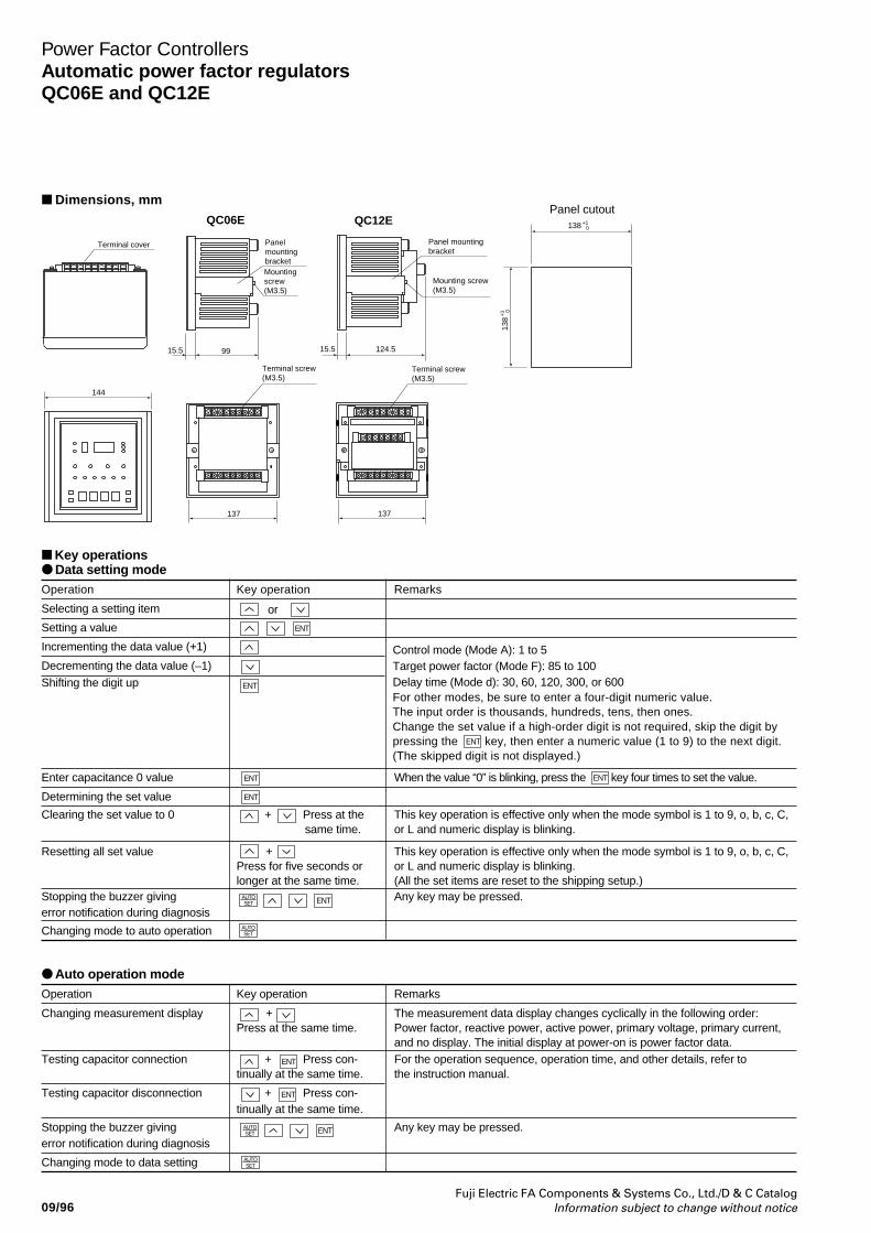
Fuji Electric FA Components & Systems Co., Ltd./D & C CatalogInformation subject to change without notice09/96
Power Factor ControllersAutomatic power factor regulatorsQC06E and QC12E
Panel mountingbracket
Panelmountingbracket
Mounting screw(M3.5)
Terminal screw(M3.5)
Terminal screw(M3.5)
Mountingscrew(M3.5)
124.515.59915.5
QC06E QC12EPanel cutout
144
137 137
Terminal cover
138 +10
138
+1 0
Dimensions, mm
Key operations Data setting modeOperation Key operation Remarks
Selecting a setting item or
Setting a value
Incrementing the data value (+1)
Decrementing the data value (–1)Shifting the digit up
Enter capacitance 0 value When the value “0” is blinking, press the ENT key four times to set the value.
Determining the set value
Clearing the set value to 0 + Press at the This key operation is effective only when the mode symbol is 1 to 9, o, b, c, C,same time. or L and numeric display is blinking.
Resetting all set value + This key operation is effective only when the mode symbol is 1 to 9, o, b, c, C,Press for five seconds or or L and numeric display is blinking.longer at the same time. (All the set items are reset to the shipping setup.)
Stopping the buzzer giving Any key may be pressed.error notification during diagnosis
Changing mode to auto operation
Auto operation modeOperation Key operation Remarks
Changing measurement display + The measurement data display changes cyclically in the following order:Press at the same time. Power factor, reactive power, active power, primary voltage, primary current,
and no display. The initial display at power-on is power factor data.Testing capacitor connection + Press con- For the operation sequence, operation time, and other details, refer to
tinually at the same time. the instruction manual.
Testing capacitor disconnection + Press con-tinually at the same time.
Stopping the buzzer giving Any key may be pressed.error notification during diagnosis
Changing mode to data setting
AUTOSET
ENT
ENT
ENT
ENT
ENT
AUTOSET
ENT
ENT
AUTOSET
Control mode (Mode A): 1 to 5Target power factor (Mode F): 85 to 100Delay time (Mode d): 30, 60, 120, 300, or 600For other modes, be sure to enter a four-digit numeric value.The input order is thousands, hundreds, tens, then ones.Change the set value if a high-order digit is not required, skip the digit bypressing the ENT key, then enter a numeric value (1 to 9) to the next digit.(The skipped digit is not displayed.)
AUTOSET ENT
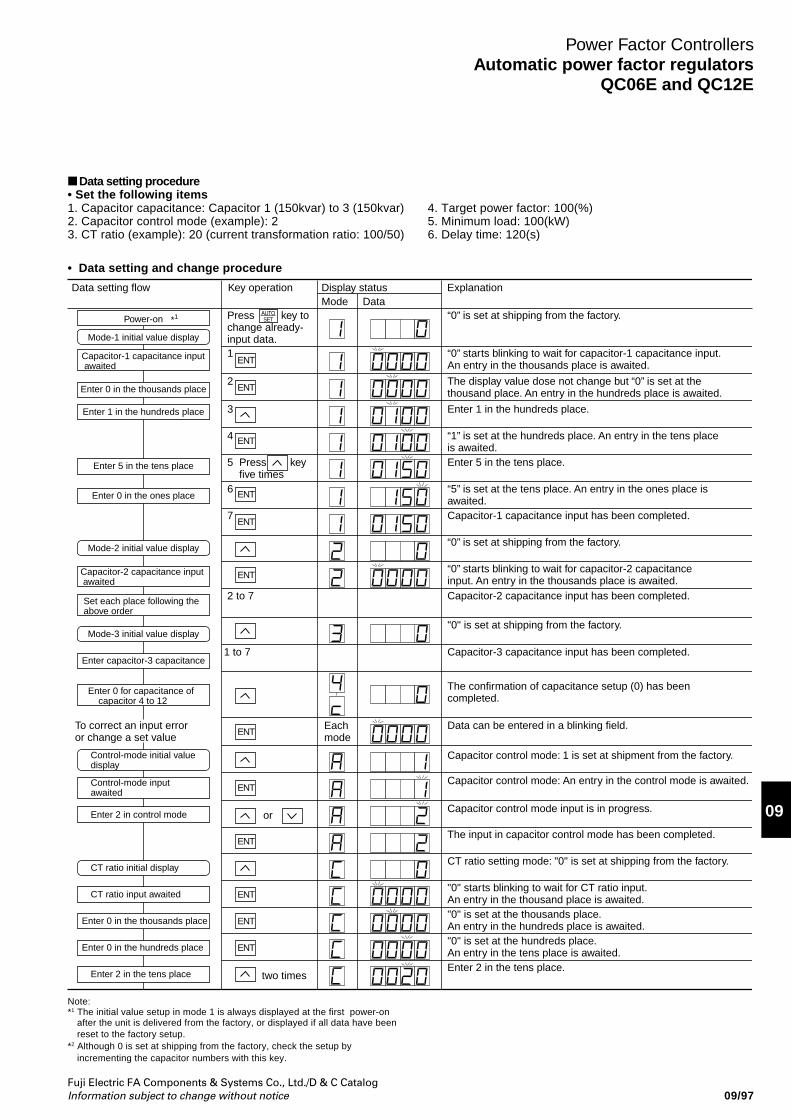
Fuji Electric FA Components & Systems Co., Ltd./D & C CatalogInformation subject to change without notice
09
09/97
Power Factor ControllersAutomatic power factor regulators
QC06E and QC12E
• Data setting and change procedure
Data setting procedure• Set the following items1. Capacitor capacitance: Capacitor 1 (150kvar) to 3 (150kvar)2. Capacitor control mode (example): 23. CT ratio (example): 20 (current transformation ratio: 100/50)
4. Target power factor: 100(%)5. Minimum load: 100(kW)6. Delay time: 120(s)
Note:*1 The initial value setup in mode 1 is always displayed at the first power-on
after the unit is delivered from the factory, or displayed if all data have beenreset to the factory setup.
*2 Although 0 is set at shipping from the factory, check the setup byincrementing the capacitor numbers with this key.
“0” is set at shipping from the factory.
“0” starts blinking to wait for capacitor-1 capacitance input. An entry in the thousands place is awaited.
The display value dose not change but “0” is set at thethousand place. An entry in the hundreds place is awaited.
Enter 1 in the hundreds place.
“1” is set at the hundreds place. An entry in the tens placeis awaited.Enter 5 in the tens place.
“5” is set at the tens place. An entry in the ones place isawaited.Capacitor-1 capacitance input has been completed.
“0” is set at shipping from the factory.
“0” starts blinking to wait for capacitor-2 capacitanceinput. An entry in the thousands place is awaited.Capacitor-2 capacitance input has been completed.
Press key to change already-input data.1
2
3
4
5 Press keyfive times
6
7
2 to 7
two times
Eachmode
Data can be entered in a blinking field.To correct an input error or change a set value
Capacitor control mode: 1 is set at shipment from the factory.
Capacitor control mode: An entry in the control mode is awaited.
Capacitor control mode input is in progress.
The input in capacitor control mode has been completed.
CT ratio setting mode: "0" is set at shipping from the factory.
"0" starts blinking to wait for CT ratio input.An entry in the thousand place is awaited."0" is set at the thousands place.An entry in the hundreds place is awaited."0" is set at the hundreds place.An entry in the tens place is awaited.Enter 2 in the tens place.
"0" is set at shipping from the factory.
Capacitor-3 capacitance input has been completed.1 to 7
or
The confirmation of capacitance setup (0) has beencompleted.
Power-on *1
Enter 0 in the thousands place
Enter 1 in the hundreds place
Enter 5 in the tens place
Enter 0 in the ones place
Mode-2 initial value display
Mode-3 initial value display
Enter capacitor-3 capacitance
Mode-1 initial value display
Capacitor-1 capacitance input awaited
Capacitor-2 capacitance input awaited
Set each place following theabove order
Control-mode initial value display
Control-mode input awaited
Enter 2 in control mode
CT ratio initial display
CT ratio input awaited
Enter 0 in the thousands place
Enter 0 in the hundreds place
Enter 2 in the tens place
Enter 0 for capacitance of capacitor 4 to 12
Data setting flow Key operation Display statusMode Data
Explanation
AUTOSET
ENT
ENT
ENT
ENT
ENT
ENT
ENT
ENT
ENT
ENT
ENT
ENT
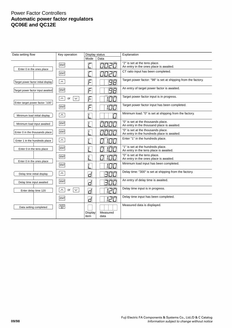
Fuji Electric FA Components & Systems Co., Ltd./D & C CatalogInformation subject to change without notice09/98
Power Factor ControllersAutomatic power factor regulatorsQC06E and QC12E
"2" is set at the tens place.An entry in the ones place is awaited.
Enter 0 in the ones placeCT ratio input has been completed.
Target power factor: "98" is set at shipping from the factory.Target power factor initial display
An entry of target power factor is awaited.Target power factor input awaited
Target power factor input is in progress.
Enter target power factor "100"Target power factor input has been completed.
Minimum load: "0" is set at shipping from the factory.Minimum load initial display
"0" is set at the thousands place.An entry in the thousand place is awaited.Minimum load input awaited
"0" is set at the thousands place.An entry in the hundreds place is awaited.Enter 0 in the thousands place
Enter "1" in the hundreds place.Enter 1 in the hundreds place
"1" is set at the hundreds place.An entry in the tens place is awaited.Enter 0 in the tens place
"0" is set at the tens place.An entry in the ones place is awaited.
Enter 0 in the ones placeMinimum load input has been completed.
Delay time: "300" is set at shipping from the factory.Delay time initial display
An entry of delay time is awaited.Delay time input awaited
Delay time input is in progress.Enter delay time 120
Delay time input has been completed.
Measured data is displayed.
Displayitem
Measureddata
Data setting completed
Data setting flow Key operation Display statusMode Data
Explanation
ENT
ENT
ENT
ENT
ENT
ENT
ENT
ENT
ENT
ENT
ENT
or
or
AUTOSET
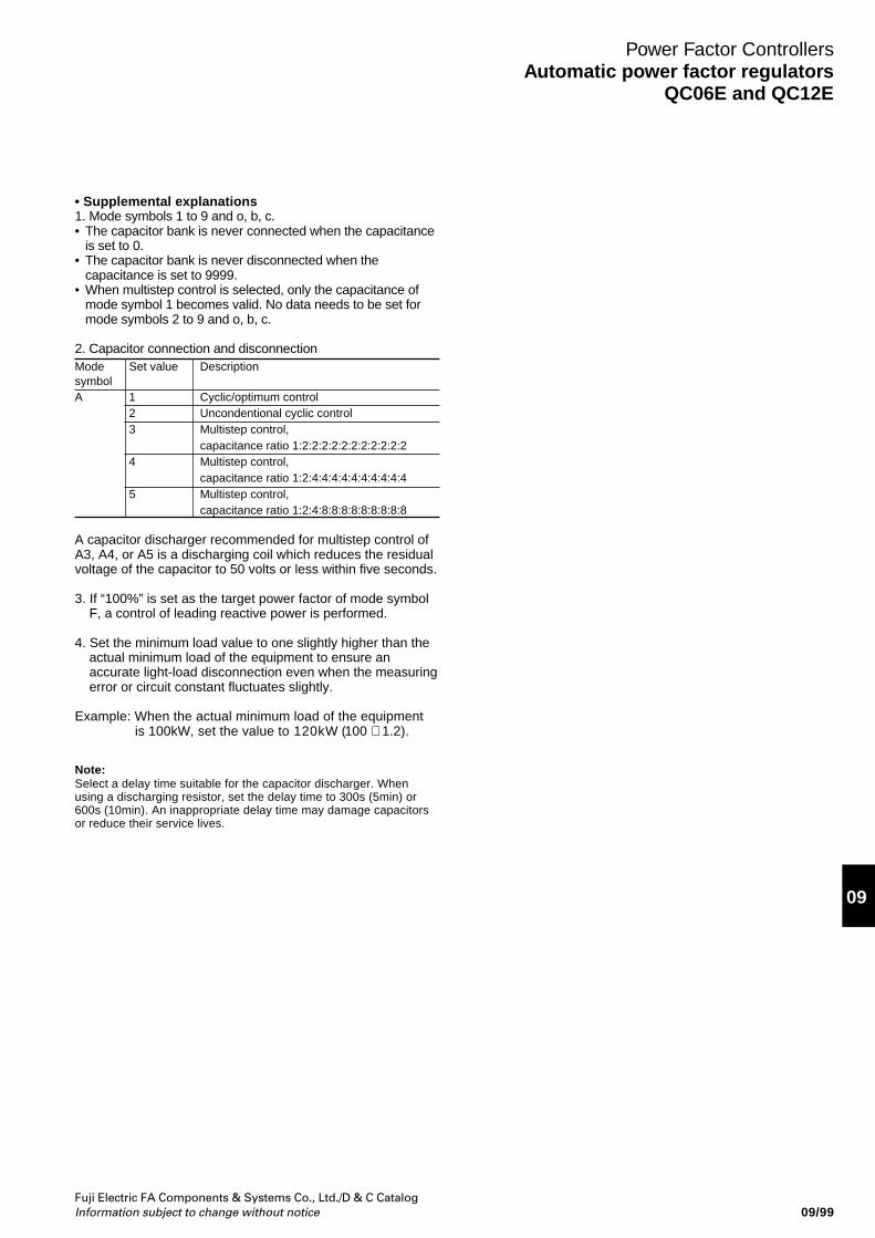
Fuji Electric FA Components & Systems Co., Ltd./D & C CatalogInformation subject to change without notice
09
09/99
Power Factor ControllersAutomatic power factor regulators
QC06E and QC12E
• Supplemental explanations1. Mode symbols 1 to 9 and o, b, c.• The capacitor bank is never connected when the capacitance
is set to 0.• The capacitor bank is never disconnected when the
capacitance is set to 9999.• When multistep control is selected, only the capacitance of
mode symbol 1 becomes valid. No data needs to be set formode symbols 2 to 9 and o, b, c.
2. Capacitor connection and disconnectionMode Set value DescriptionsymbolA 1 Cyclic/optimum control
2 Uncondentional cyclic control3 Multistep control,
capacitance ratio 1:2:2:2:2:2:2:2:2:2:2:24 Multistep control,
capacitance ratio 1:2:4:4:4:4:4:4:4:4:4:45 Multistep control,
capacitance ratio 1:2:4:8:8:8:8:8:8:8:8:8
A capacitor discharger recommended for multistep control ofA3, A4, or A5 is a discharging coil which reduces the residualvoltage of the capacitor to 50 volts or less within five seconds.
3. If “100%” is set as the target power factor of mode symbolF, a control of leading reactive power is performed.
4. Set the minimum load value to one slightly higher than theactual minimum load of the equipment to ensure anaccurate light-load disconnection even when the measuringerror or circuit constant fluctuates slightly.
Example: When the actual minimum load of the equipment is 100kW, set the value to 1 2 0 k W (100 × 1.2).
Note:Select a delay time suitable for the capacitor discharger. Whenusing a discharging resistor, set the delay time to 300s (5min) or600s (10min). An inappropriate delay time may damage capacitorsor reduce their service lives.
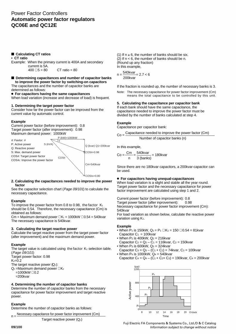
Fuji Electric FA Components & Systems Co., Ltd./D & C CatalogInformation subject to change without notice09/100
Power Factor ControllersAutomatic power factor regulatorsQC06E and QC12E
Calculating CT ratios• CT ratioExample: When the primary current is 400A and secondary
current is 5A.400 ÷ 5 = 80 CT ratio = 80
Determining capacitances and number of capacitor banksto improve the power factor by switching-on capacitors
The capacitances and the number of capacitor banks aredetermined as follows: For capacitors having the same capacitancesWhen load variation (increase and decrease of load) is frequent.
1. Determining the target power factorConsider how far the power factor can be improved from thecurrent value by automatic control.
ExampleCurrent power factor (before improvement): 0.8Target power factor (after improvement): 0.98Maximum demand power: 1000kW
2. Calculating the capacitances needed to improve the powerfactor
See the capacitor selection chart (Page 09/101) to calculate thenecessary capacitance.
ExampleTo improve the power factor from 0.8 to 0.98, t h e f a c t o r K1
should be 0.54. Therefore, the necessary capacitance (Cm) isobtained as follows:Cm = Maximum demand power × K1 = 1000kW × 0.54 = 540kvarThe necessary capacitance is 540kvar.
3. Calculating the target reactive powerCalculate the target reactive power from the target power factor(after improvement) and the maximum demand power.
ExampleThe target value is calculated using t h e f a c t o r K2 selection table.(Page 09/101)Target power factor: 0.98K2=0.2The target reactive power (Q1):Q1 =Maximum demand power × K2
=1000kW × 0.2=200kvar
4. Determining the number of capacitor banksDetermine the number of capacitor banks from the necessarycapacitance for power factor improvement and target reactivepower.
ExampleDetermine the number of capacitor banks as follows:
n = Necessary capacitance for power factor improvement (Cm)
Target reactive power (Q1)
(1) If n ≥ 6, the number of banks should be six.(2) If n < 6, the number of banks should be n.(Round up any fraction)In this example,
n = 540kvar
= 2.7 < 6200kvar
If the fraction is rounded up, the number of necessary banks is 3.
Note: The necessary capacitance for power factor improvement (Cm)means the total capacitance to be controlled by this unit.
5. Calculating the capacitance per capacitor bankIf each bank should have the same capacitance, thecapacitance needed to improve the power factor must bedivided by the number of banks calculated at step 4.
ExampleCapacitance per capacitor bank:
Co = Capacitance needed to improve the power factor (Cm)
Number of capacitor banks (n)
In this example,
Co = Cm
= 540kvar
= 180kvarn 3 (banks)
Since there are no 180kvar capacitors, a 200kvar-capacitor canbe used.
For capacitors having unequal-capacitancesWhen load variation is a slight and stable all the year round.Target power factor and the necessary capacitance for powerfactor improvement are calculated using step 1 and 2.
Current power factor (before improvement): 0.8Target power factor (after inprovement): 0.98Necessary capacitance for power factor improvement (Cm):540kvarFor load variation as shown below, calculate the reactive powervariation using K1.
Example• When P1 is 150kW, Q1 = P1 × K1 = 150 × 0.54 = 81kvar
Capacitor C1 = 100kvar• When P2 is 400kW, Q2 = 216kvar
Capacitor C2 = Q2 – C1 = 116kvar, C2 = 150kvar• When P3 is 600kW, Q3 = 324kvar
Capacitor C3 = Q3 – (C1 + C2) = 74kvar, C3 = 100kvar• When P4 is 1000kW, Q4 = 540kvar
Capacitor C4 = Q4 – (C1 + C2+ C3) = 190kvar, C4 = 200kvar
θ: Favtor: θP: Active powerQ: Reactive powerS: Max. demand powerCOSθ: Target power factorCOSθ0: Improve the power factor
θ
COSθ
COSθ=0.98
COSθ0=0.80
P (kW)=1000kW
Cm=540kvar
S (kVA)Q (kvar) Q1=200kvar
1200
800
400
08 10 12 14 16 18 20 O'clock
Time
(kW)
Act
ive
pow
er
P4
P3
P2
P1
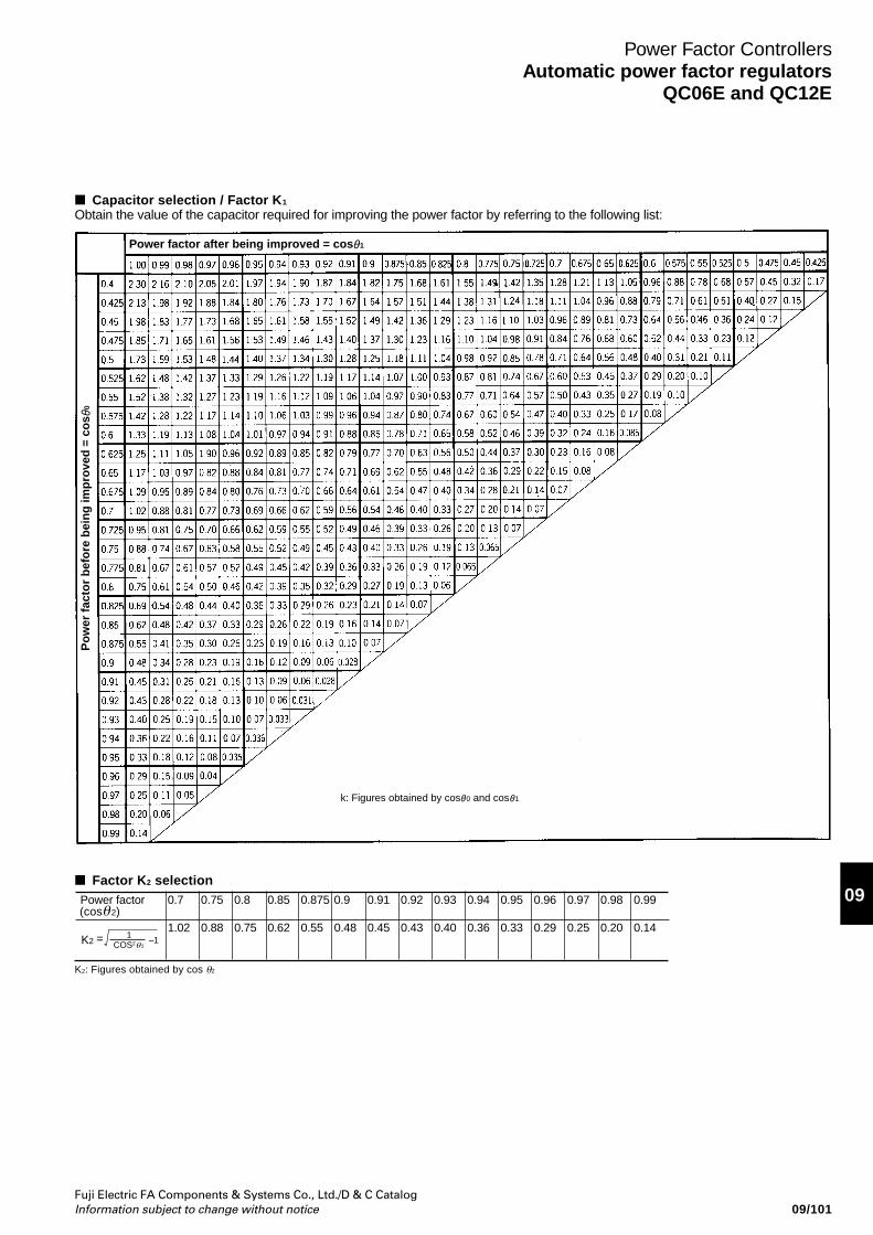
Fuji Electric FA Components & Systems Co., Ltd./D & C CatalogInformation subject to change without notice
09
09/101
Power Factor ControllersAutomatic power factor regulators
QC06E and QC12E
Capacitor selection / Factor K 1Obtain the value of the capacitor required for improving the power factor by referring to the following list:
Power factor 0.7 0.75 0.8 0.85 0.875 0.9 0.91 0.92 0.93 0.94 0.95 0.96 0.97 0.98 0.99
1.02 0.88 0.75 0.62 0.55 0.48 0.45 0.43 0.40 0.36 0.33 0.29 0.25 0.20 0.14(cosθ2)
COS2θ1K2 = –1
2
Factor K2 selection
K2: Figures obtained by cos θ2
Power factor after being improved = cos 1
Po
wer
fac
tor
bef
ore
bei
ng
imp
rove
d =
co
s 0
k: Figures obtained by cos 0 and cos 1
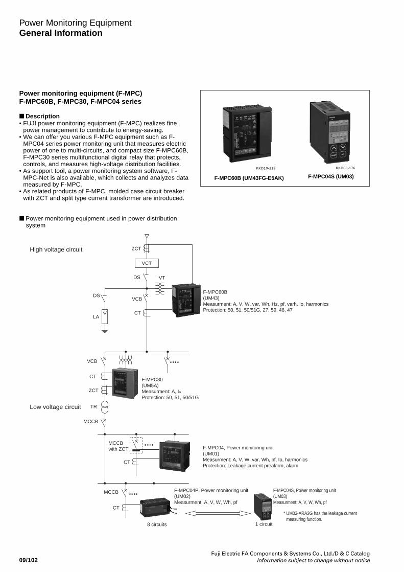
Fuji Electric FA Components & Systems Co., Ltd./D & C CatalogInformation subject to change without notice09/102
ZCTHigh voltage circuit
Low voltage circuit
VCT
DS VT
F-MPC60B(UM43)Measurment: A, V, W, var, Wh, Hz, pf, varh, Io, harmonicsProtection: 50, 51, 50/51G, 27, 59, 46, 47
F-MPC30(UM5A)Measurment: A, Io Protection: 50, 51, 50/51G
F-MPC04, Power monitoring unit(UM01)Measurment: A, V, W, var, Wh, pf, Io, harmonicsProtection: Leakage current prealarm, alarm
F-MPC04P, Power monitoring unit(UM02)Measurment: A, V, W, Wh, pf
F-MPC04S, Power monitoring unit(UM03)Measurment: A, V, W, Wh, pf
* UM03-ARA3G has the leakage currentmeasuring function.
VCB
CTLA
DS
VCB
CT
ZCT
TR
MCCBwith ZCT
MCCB
8 circuits 1 circuit
CT
MCCB
CT
Power Monitoring EquipmentGeneral Information
Power monitoring equipment (F-MPC)F-MPC60B, F-MPC30, F-MPC04 series
Description• FUJI power monitoring equipment (F-MPC) realizes fine
power management to contribute to energy-saving.• We can offer you various F-MPC equipment such as F-
MPC04 series power monitoring unit that measures electricpower of one to multi-circuits, and compact size F-MPC60B,F-MPC30 series multifunctional digital relay that protects,controls, and measures high-voltage distribution facilities.
• As support tool, a power monitoring system software, F-MPC-Net is also available, which collects and analyzes datameasured by F-MPC.
• As related products of F-MPC, molded case circuit breakerwith ZCT and split type current transformer are introduced.
Power monitoring equipment used in power distributionsystem
F-MPC60B (UM43FG-E5AK)
KKD10-119
F-MPC04S (UM03)
KKD08-176
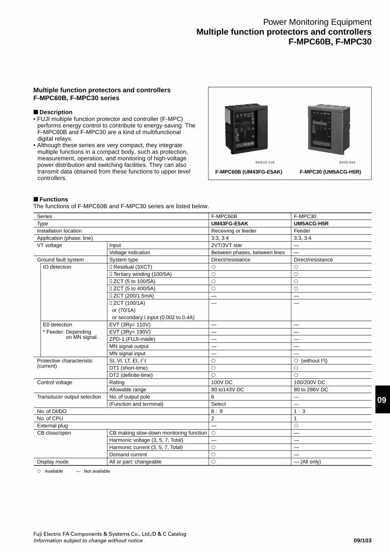
Fuji Electric FA Components & Systems Co., Ltd./D & C CatalogInformation subject to change without notice
09
09/103
Power Monitoring EquipmentMultiple function protectors and controllers
F-MPC60B, F-MPC30
Multiple function protectors and controllersF-MPC60B, F-MPC30 series
Description• FUJI multiple function protector and controller (F-MPC)
performs energy control to contribute to energy-saving. TheF-MPC60B and F-MPC30 are a kind of multifunctionaldigital relays.
• Although these series are very compact, they integratemultiple functions in a compact body, such as protection,measurement, operation, and monitoring of high-voltagepower distribution and switching facilities. They can alsotransmit data obtained from these functions to upper levelcontrollers.
F-MPC60B (UM43FG-E5AK)
KK02-042KKD10-119
F-MPC30 (UM5ACG-H5R)
FunctionsThe functions of F-MPC60B and F-MPC30 series are listed below.
SeriesTypeInstallation locationApplication (phase: line)VT voltage
Ground fault system
Protective characteristic (current)
Control voltage
Transducer output selection
No. of DI/DONo. of CPUExternal plugCB close/open
Display mode
IO detection
E0 detection* Feeder: Depending
on MN signal.
F-MPC60BUM43FG-E5AKReceiving or feeder3:3, 3:42VT/3VT starBetween phases, between linesDirect/resistance——
—————100V DC80 to143V DC6Select8 : 82——
F-MPC30UM5ACG-H5RFeeder3:3, 3:4——Direct/resistance——
————— (without I2t)100/200V DC80 to 286V DC——1 : 31————— (All only)
InputVoltage indicationSystem type①Residual (3XCT)➁Ter tiary winding (100/5A)➂ZCT (5 to 100/5A)➃ZCT (5 to 400/5A)➄ZCT (200/1.5mA)➅ZCT (100/1A) or (70/1A) or secondary I input (0.002 to 0.4A)EVT (3Ry= 110V)EVT (3Ry= 190V)ZPD-1 (FUJI-made)MN signal outputMN signal inputSI, VI, LT, EI, I2 tDT1 (short-time)DT2 (definite-time)RatingAllowable rangeNo. of output pole(Function and terminal)
CB making slow-down monitoring functionHarmonic voltage (3, 5, 7, Total)Harmonic current (3, 5, 7, Total)Demand current All or part: changeable
Available Not available—
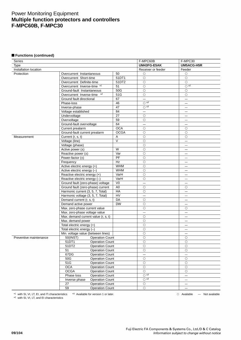
Fuji Electric FA Components & Systems Co., Ltd./D & C CatalogInformation subject to change without notice09/104
Power Monitoring EquipmentMultiple function protectors and controllersF-MPC60B, F-MPC30
Functions (continued)
SeriesTypeInstallation locationProtection
Measurement
Preventive maintenance
*1 with SI, VI, LT, EI, and I2t characteristics*2 with SI, VI, LT, and EI characteristics
*3 Available for version 1 or later.
F-MPC60BUM43FG-E5AKReceiver or feeder
– *3
*3
–––––– *3
*3
F-MPC30UM5ACG-H5RFeeder
*2
–––––––––––––––––––––––––––––––––
Overcurrent InstantaneousOvercurrent Short-timeOvercurrent Definite-timeOvercurrent Inverse-time *1
Ground-fault InstantaneousOvercurrent Inverse-time *2
Ground fault directional Phase-lossInverse-phaseVoltage establishedUndervoltageOvervoltageGround-fault overvoltageCurrent prealarmGround-fault current prealarmCurrent (r, s, t)Voltage (line)Voltage (phase)Active power (±)Reactive power (±)Power-factor (±)FrequencyActive electric energy (+)Active electric energy (–)Reactive electric energy (+)Reactive electric energy (–)Ground fault (zero-phase) voltage Ground fault (zero-phase) currentHarmonic current (3, 5, 7, Total)Harmonic voltage (3, 5, 7, Total)Demand current (r, s, t)Demand active power Max. zero-phase current valueMax. zero-phase voltage valueMax. demand current value (r, s, t) Max. demand power Total electric energy (+)Total electric energy (–)Min. voltage value (between lines)
50(INST) Operation Count51DT1 Operation Count51DT2 Operation Count51 Operation Count67DG Operation Count50G Operation Count51G Operation CountOCA Operation CountOCGA Operation CountPhase loss Operation CountInverse phase Operation Count27 Operation Count59 Operation Count
5051DT151DT25150G51G67464784275964OCAOCGAAV
WVarPFHzWHMWHMVarHVarHV0A0HAHVDADW
Available — Not available
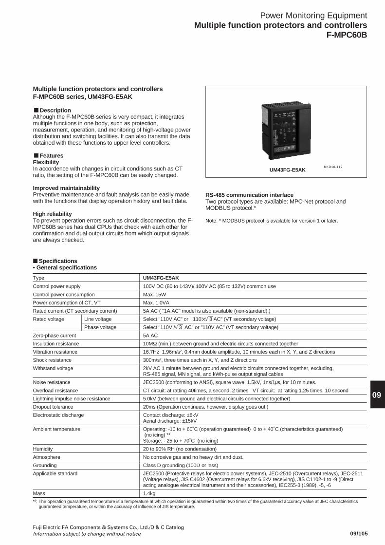
09/105Fuji Electric FA Components & Systems Co., Ltd./D & C CatalogInformation subject to change without notice
Power Monitoring EquipmentMultiple function protectors and controllers
F-MPC60B
09
Multiple function protectors and controllersF-MPC60B series, UM43FG-E5AK
DescriptionAlthough the F-MPC60B series is very compact, it integratesmultiple functions in one body, such as protection,measurement, operation, and monitoring of high-voltage powerdistribution and switching facilities. It can also transmit the dataobtained with these functions to upper level controllers.
FeaturesFlexibilityIn accordence with changes in circuit conditions such as CTratio, the setting of the F-MPC60B can be easily changed.
Improved maintainabilityPreventive maintenance and fault analysis can be easily madewith the functions that display operation history and fault data.
High reliabilityTo prevent operation errors such as circuit disconnection, the F-MPC60B series has dual CPUs that check with each other forconfirmation and dual output circuits from which output signalsare always checked.
UM43FG-E5AK
RS-485 communication interfaceTwo protocol types are available: MPC-Net protocol andMODBUS protocol.*
Note: * MODBUS protocol is available for version 1 or later.
KKD10-119
Type UM43FG-E5AK
Control power supply 100V DC (80 to 143V)/ 100V AC (85 to 132V) common use
Control power consumption Max. 15W
Power consumption of CT, VT Max. 1.0VA
Rated current (CT secondary current) 5A AC ( "1A AC" model is also available (non-standard).)
Rated voltage Line voltage Select "110V AC" or " 110 √—3 AC" (VT secondary voltage)
Phase voltage Select "110V /√—3 AC" or "110V AC" (VT secondary voltage)
Zero-phase current 5A AC
Insulation resistance 10MΩ (min.) between ground and electric circuits connected together
Vibration resistance 16.7Hz 1.96m/s2, 0.4mm double amplitude, 10 minutes each in X, Y, and Z directions
Shock resistance 300m/s2, three times each in X, Y, and Z directions
Withstand voltage 2kV AC 1 minute between ground and electric circuits connected together, excluding,RS-485 signal, MN signal, and kWh-pulse output signal cables
Noise resistance JEC2500 (conforming to ANSI), square wave, 1.5kV, 1ns/1µs, for 10 minutes.
Overload resistance CT circuit: at ratting 40times, a second, 2 times VT circuit: at ratting 1.25 times, 10 second
Lightning impulse noise resistance 5.0kV (between ground and electrical circuits connected together)
Dropout tolerance 20ms (Operation continues, however, display goes out.)
Electrostatic discharge Contact discharge: ±8kVAerial discharge: ±15kV
Ambient temperature Operating: -10 to + 60˚C (operation guaranteed) 0 to + 40˚C (characteristics guaranteed) (no icing) *1
Storage: - 25 to + 70˚C (no icing)
Humidity 20 to 90% RH (no condensation)
Atmosphere No corrosive gas and no heavy dirt and dust.
Grounding Class D grounding (100Ω or less)
Applicable standard JEC2500 (Protective relays for electric power systems), JEC-2510 (Overcurrent relays), JEC-2511(Voltage relays), JIS C4602 (Overcurrent relays for 6.6kV receiving), JIS C1102-1 to -9 (Directacting analogue electrical instrument and their accessories), IEC255-3 (1989), -5, -6
Mass 1.4kg
Specifications• General specifications
*1: The operation guaranteed temperature is a temperature at which operation is guaranteed within two times of the guaranteed accuracy value at JEC characteristicsguaranteed temperature, or within the accuracy of influence of JIS temperature.
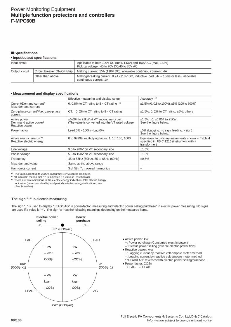
09/106Fuji Electric FA Components & Systems Co., Ltd./D & C Catalog
Information subject to change without notice
Power Monitoring EquipmentMultiple function protectors and controllersF-MPC60B
• Input/output specificationsInput circuit Applicable to both 100V DC (max. 143V) and 100V AC (max. 132V)
Pick up voltage: 40 to 70V DC/40 to 70V AC
Output circuit Circuit breaker ON/OFF/trip Making current: 15A (110V DC), allowable continuous current: 4A
Other than above Making/breaking current: 0.2A (110V DC, inductive load L/R = 15ms or less), allowablecontinuous current: 1A
Specifications
*1 The fault current up to 2000% (accuracy: ±5%) can be displayed.*2 “0, a to n%” means that “0” is indicated if a value is less than a%.*3 There are two indications in the electric energy indication; total electric energy
indication (zero clear disable) and periodic electric energy indication (zeroclear is enable).
The sign "±" in electric measuring
The sign “±" is used to display "LEAD/LAG" in power-factor. measuring and “electric power selling/purchase” in electric power measuring. No signsare used if a value is "+". The sign “±" has the following meanings depending on the measured items.
• Active power: kW +: Power purchase (Consumed electric power) –: Electric power selling (Inverse electric power flow)• Reactive power: kvar +: Lagging current by reactive volt-ampere meter method –: Leading current by reactive volt-ampere meter method * “LEAD/LAG” reverses with electric power selling/purchase.• Power factor: COSφ +:LAG –: LEAD
Electric powerselling
Powerpurchase
90° (COSφ=0)
270° (COSφ=0)
180°(COSφ=-1)
0°(COSφ=1)
LAG LEAD
LEAD LAG
– kW
– kvar
COSφ
kW
– kvar
–COSφ
– kW
kvar
–COSφ
kW
kvar
COSφ
• Measurement and display specificationsEffective measuring and display range Accuracy *2
Current/Demand current/ 0, 0.8% to CT rating to 8 × CT rating *1 ±1.5% (0, 0.8 to 100%), ±5% (100 to 800%)Max. demand current
Zero-phase current/Max. zero-phase CT: 0, 2% to CT rating to 8 × CT rating ±1.5%: 0, 2% to CT rating, ±5%: otherscurrent
Active power ±0.004 to ±1kW at VT secondary circuit ±1.5% : 0, ±0.004 to ±1kWDemmand active power/ (The value is converted into the VT rated voltage See the figure below.Reactive power
Power factor Lead 0% - 100% - Lag 0% ±5% (Lagging: no sign, leading: - sign)See the figure below.
Active electric energy *3 0 to 99999, multiplying factor: 1, 10, 100, 1000 Equivalent to ordinary instruments shown in Table 4Reactive electric energy specified in JIS C 1216 (instrument with a
transformer)
Line voltage 9.5 to 260V on VT secondary side ±1.5%
Phase voltage 5.5 to 150V on VT secondary side ±1.5%
Frequency 45 to 55Hz (50Hz), 55 to 65Hz (60Hz) ±0.5%
Max. demand value Same as the above range –
Harmonics current 3rd, 5th, 7th, overall harmonics –
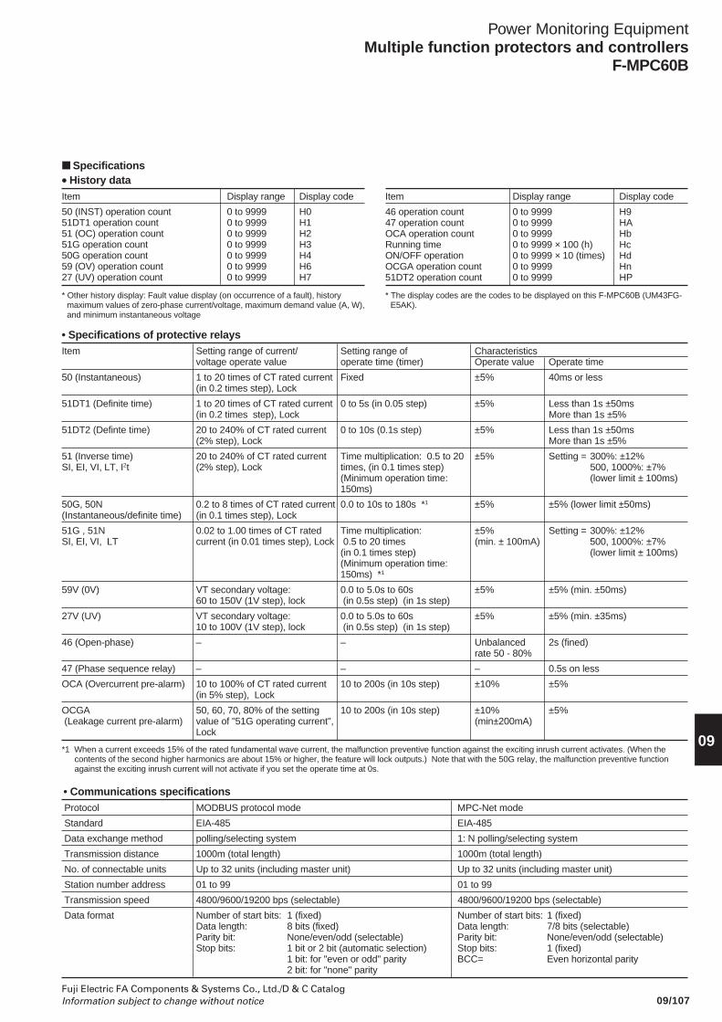
09/107Fuji Electric FA Components & Systems Co., Ltd./D & C CatalogInformation subject to change without notice
Power Monitoring EquipmentMultiple function protectors and controllers
F-MPC60B
09
• Specifications of protective relaysItem Setting range of current/ Setting range of Characteristics
voltage operate value operate time (timer) Operate value Operate time
50 (Instantaneous) 1 to 20 times of CT rated current Fixed ±5% 40ms or less(in 0.2 times step), Lock
51DT1 (Definite time) 1 to 20 times of CT rated current 0 to 5s (in 0.05 step) ±5% Less than 1s ±50ms(in 0.2 times step), Lock More than 1s ±5%
51DT2 (Definte time) 20 to 240% of CT rated current 0 to 10s (0.1s step) ±5% Less than 1s ±50ms(2% step), Lock More than 1s ±5%
51 (Inverse time) 20 to 240% of CT rated current Time multiplication: 0.5 to 20 ±5% Setting = 300%: ±12%SI, EI, VI, LT, I2t (2% step), Lock times, (in 0.1 times step) 500, 1000%: ±7%
(Minimum operation time: (lower limit ± 100ms)150ms)
50G, 50N 0.2 to 8 times of CT rated current 0.0 to 10s to 180s *1 ±5% ±5% (lower limit ±50ms)(Instantaneous/definite time) (in 0.1 times step), Lock
51G , 51N 0.02 to 1.00 times of CT rated Time multiplication: ±5% Setting = 300%: ±12%SI, EI, VI, LT current (in 0.01 times step), Lock 0.5 to 20 times (min. ± 100mA) 500, 1000%: ±7%
(in 0.1 times step) (lower limit ± 100ms)(Minimum operation time:150ms) *1
59V (0V) VT secondary voltage: 0.0 to 5.0s to 60s ±5% ±5% (min. ±50ms)60 to 150V (1V step), lock (in 0.5s step) (in 1s step)
27V (UV) VT secondary voltage: 0.0 to 5.0s to 60s ±5% ±5% (min. ±35ms)10 to 100V (1V step), lock (in 0.5s step) (in 1s step)
46 (Open-phase) – – Unbalanced 2s (fined)rate 50 - 80%
47 (Phase sequence relay) – – – 0.5s on less
OCA (Overcurrent pre-alarm) 10 to 100% of CT rated current 10 to 200s (in 10s step) ±10% ±5%(in 5% step), Lock
OCGA 50, 60, 70, 80% of the setting 10 to 200s (in 10s step) ±10% ±5% (Leakage current pre-alarm) value of "51G operating current", (min±200mA)
Lock
*1 When a current exceeds 15% of the rated fundamental wave current, the malfunction preventive function against the exciting inrush current activates. (When thecontents of the second higher harmonics are about 15% or higher, the feature will lock outputs.) Note that with the 50G relay, the malfunction preventive functionagainst the exciting inrush current will not activate if you set the operate time at 0s.
• History dataItem Display range Display code
50 (INST) operation count 0 to 9999 H051DT1 operation count 0 to 9999 H151 (OC) operation count 0 to 9999 H251G operation count 0 to 9999 H350G operation count 0 to 9999 H459 (OV) operation count 0 to 9999 H627 (UV) operation count 0 to 9999 H7
Item Display range Display code
46 operation count 0 to 9999 H947 operation count 0 to 9999 HAOCA operation count 0 to 9999 HbRunning time 0 to 9999 × 100 (h) HcON/OFF operation 0 to 9999 × 10 (times) HdOCGA operation count 0 to 9999 Hn51DT2 operation count 0 to 9999 HP
* Other history display: Fault value display (on occurrence of a fault), historymaximum values of zero-phase current/voltage, maximum demand value (A, W),and minimum instantaneous voltage
Specifications
• Communications specifications Protocol MODBUS protocol mode MPC-Net mode
Standard EIA-485 EIA-485
Data exchange method polling/selecting system 1: N polling/selecting system
Transmission distance 1000m (total length) 1000m (total length)
No. of connectable units Up to 32 units (including master unit) Up to 32 units (including master unit)
Station number address 01 to 99 01 to 99
Transmission speed 4800/9600/19200 bps (selectable) 4800/9600/19200 bps (selectable)
Data format Number of start bits: 1 (fixed) Number of start bits: 1 (fixed)Data length: 8 bits (fixed) Data length: 7/8 bits (selectable)Parity bit: None/even/odd (selectable) Parity bit: None/even/odd (selectable)Stop bits: 1 bit or 2 bit (automatic selection) Stop bits: 1 (fixed)
1 bit: for "even or odd" parity BCC= Even horizontal parity2 bit: for "none" parity
* The display codes are the codes to be displayed on this F-MPC60B (UM43FG-E5AK).
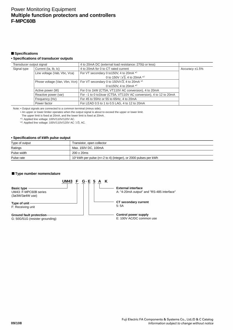
09/108Fuji Electric FA Components & Systems Co., Ltd./D & C Catalog
Information subject to change without notice
Power Monitoring EquipmentMultiple function protectors and controllersF-MPC60B
Type number nomenclature
External interfaceA: "4-20mA output" and "RS-485 interface"
CT secondary current5: 5A
Control power supplyE: 100V AC/DC common use
Type of unitF: Receiving unit
Ground fault protectionG: 50G/51G (resister grounding)
UM43 - E 5F G A K
Basic typeUM43: F-MPC60B series(3ø3W/3ø4W use)
• Specifications of transducer outputs
Transducer output signalSignal type
Note: • Output signals are connected to a common terminal (minus side).• An upper or lower limiter operates when the output signal is about to exceed the upper or lower limit. The upper limit is fixed at 20mA, and the lower limit is fixed at 20mA. *1: Applied line voltage: 100V/110V/120V AC.*2: Applied line voltage: 100V/110V/120V AC ×√3, AC.
4 to 20mA DC (external load resistance: 270Ω or less)4 to 20mA for 0 to CT rated currentFor VT secondary 0 to150V, 4 to 20mA *1
0 to 150V ×√3, 4 to 20mA *2
For VT secondary 0 to 150V/√3, 4 to 20mA *1
0 to150V, 4 to 20mA *2
For 0 to 1kW (CT5A, VT110V AC conversion), 4 to 20mAFor –1 to 0 to1kvar (CT5A, VT110V AC conversion), 4 to 12 to 20mAFor 45 to 55Hz or 55 to 65Hz, 4 to 20mAFor LEAD 0.5 to 1 to 0.5 LAG, 4 to 12 to 20mA
Accuracy ±1.5%Current (Ia, Ib, Ic)Line voltage (Vab, Vbc, Vca)
Phose voltage (Van, Vbn, Vcn)
Active power (W)Reactive power (var)Frequency (Hz)Power factor
Specifications
• Specifications of kWh pulse outputType of output Transistor, open collector
Ratings Max. 150V DC, 100mA
Pulse width 200 ± 20ms
Pulse rate 10n kWh per pulse (n=-2 to 4) (integer), or 2000 pulses per kWh
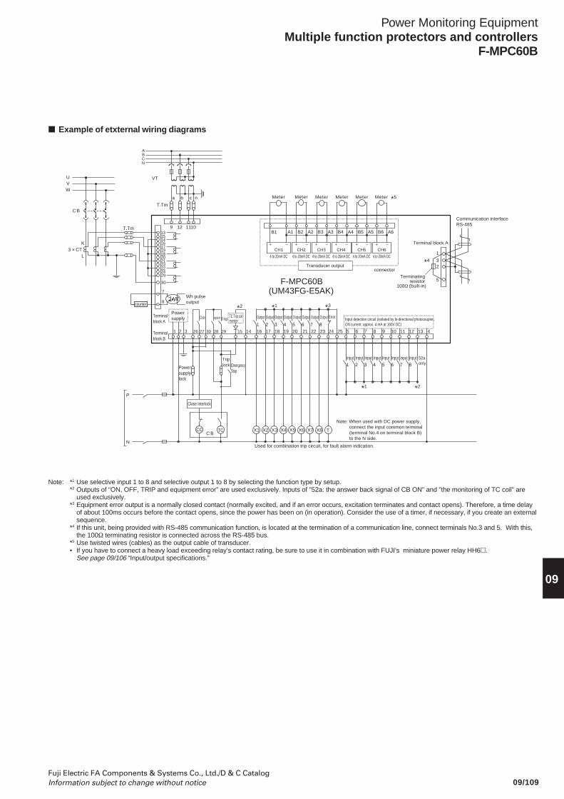
09/109Fuji Electric FA Components & Systems Co., Ltd./D & C CatalogInformation subject to change without notice
Power Monitoring EquipmentMultiple function protectors and controllers
F-MPC60B
09
Example of etxternal wiring diagrams
Note: *1 Use selective input 1 to 8 and selective output 1 to 8 by selecting the function type by setup.*2 Outputs of “ON, OFF, TRIP and equipment error” are used exclusively. Inputs of "52a: the answer back signal of CB ON" and "the monitoring of TC coil" are
used exclusively.*3 Equipment error output is a normally closed contact (normally excited, and if an error occurs, excitation terminates and contact opens). Therefore, a time delay
of about 100ms occurs before the contact opens, since the power has been on (in operation). Consider the use of a timer, if necessary, if you create an externalsequence.
*4 If this unit, being provided with RS-485 communication function, is located at the termination of a communication line, connect terminals No.3 and 5. With this,the 100Ω terminating resistor is connected across the RS-485 bus.
*5 Use twisted wires (cables) as the output cable of transducer.• If you have to connect a heavy load exceeding relay’s contact rating, be sure to use it in combination with FUJI’s miniature power relay HH6.
See page 09/106 “Input/output specifications.”
ABCN
a b c n
T.Tm
VT
Communication interface RS-485
Note: When used with DC power supply, connect the input common terminal (terminal No.4 on terminal block B) to the N side.
X1 X2 X3 X4 X5 T
Used for combination trip circuit, for fault alarm indication.
P
N
9 12 1110
Input detection circuit (isolated by bi-directional photocoupler, ON current: approx. 4 mA at 100V DC)
Terminal block A
1
32
5
25 5 6 7 8 9 10 11 12 13 4
21 3 4 5 6
Input
7
Input
8
InputInputInputInputInputInput
5
20 2421 22 23
Output
X6
6
Output
X7
7
Output
X8
8
Output Error
1 2 3 4
Output Output Output Output
F-MPC60B(UM43FG-E5AK)
16 17 18 192 31
Terminalblock A
Terminalblock B
Powersupply
Terminating resistor
100Ω (built-in)
52a only
Meter Meter Meter Meter Meter Meter
B1 A1 B2 A2 B3 A3 B4 A4 B5 A5 B6 A6
CH1 CH3 CH4 CH5 CH6CH2
4 to 20mA DC 4 to 20mA DC 4 to 20mA DC 4 to 20mA DC 4 to 20mA DC 4 to 20mA DC
Transducer outputconnector
+ – + – + – + – + – + –
UVW
T.Tm
3 × CT K
L
C B
13
14
17
18
21
22
29
30
7
15
16
19
20
23
24
8Wh pulseoutputcounter
14
*2 *1
*1 *2
*4
*5
*3
Emergency Stop
Trip lock
C BCC TC
Powersupplylock
TC Trip coil monitor
Close open Trip
26 27 30 28 29 15
Close interlock
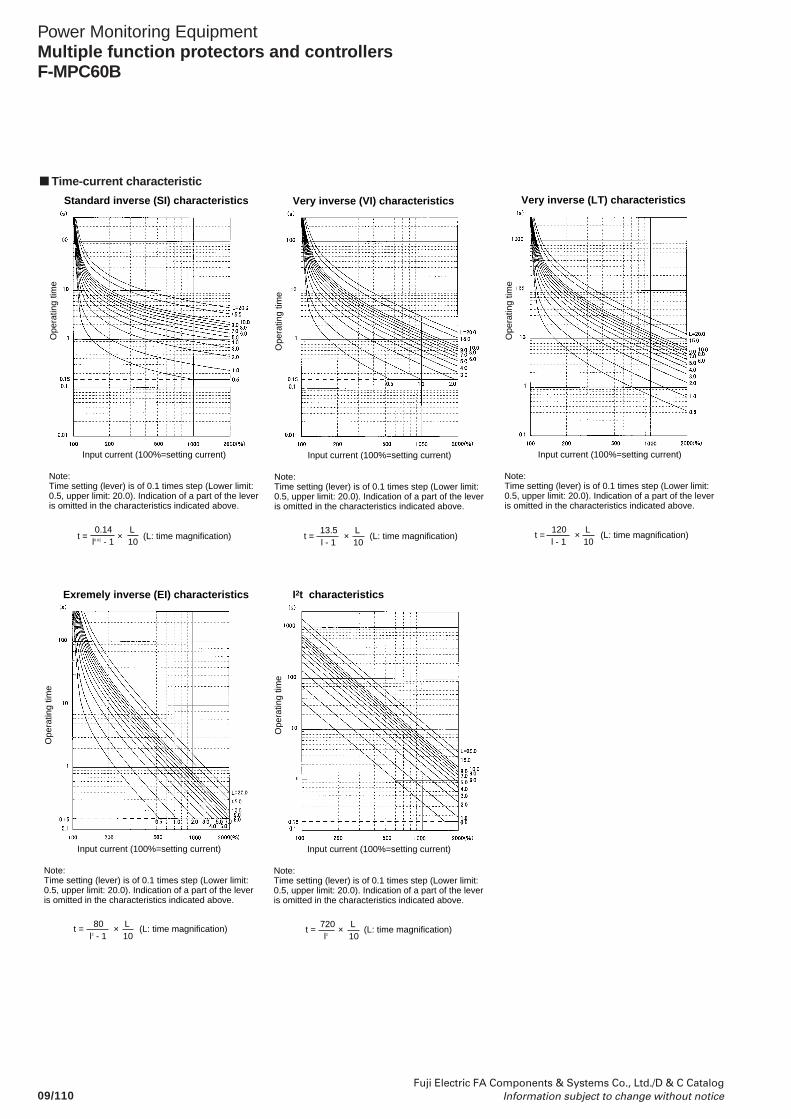
09/110Fuji Electric FA Components & Systems Co., Ltd./D & C Catalog
Information subject to change without notice
Power Monitoring EquipmentMultiple function protectors and controllersF-MPC60B
Time-current characteristic
Ope
ratin
g tim
e
Input current (100%=setting current)
Note:Time setting (lever) is of 0.1 times step (Lower limit: 0.5, upper limit: 20.0). Indication of a part of the lever is omitted in the characteristics indicated above.
l - 113.5
10L
Very inverse (VI) characteristics
Ope
ratin
g tim
e
Input current (100%=setting current)
Note:Time setting (lever) is of 0.1 times step (Lower limit: 0.5, upper limit: 20.0). Indication of a part of the lever is omitted in the characteristics indicated above.
t = × (L: time magnification)
t = × (L: time magnification)t = × (L: time magnification)
l2 - 180
10L
Exremely inverse (EI) characteristics
Ope
ratin
g tim
e
Input current (100%=setting current)
Note:Time setting (lever) is of 0.1 times step (Lower limit: 0.5, upper limit: 20.0). Indication of a part of the lever is omitted in the characteristics indicated above.
l0.02 - 10.14
10L
Standard inverse (SI) characteristics
Ope
ratin
g tim
e
Input current (100%=setting current)
Note:Time setting (lever) is of 0.1 times step (Lower limit: 0.5, upper limit: 20.0). Indication of a part of the lever is omitted in the characteristics indicated above.
l - 1120
10L
Very inverse (LT) characteristics
t = × (L: time magnification)
Ope
ratin
g tim
e
Input current (100%=setting current)
Note:Time setting (lever) is of 0.1 times step (Lower limit: 0.5, upper limit: 20.0). Indication of a part of the lever is omitted in the characteristics indicated above.
l2 720
10L
I2t characteristics
t = × (L: time magnification)
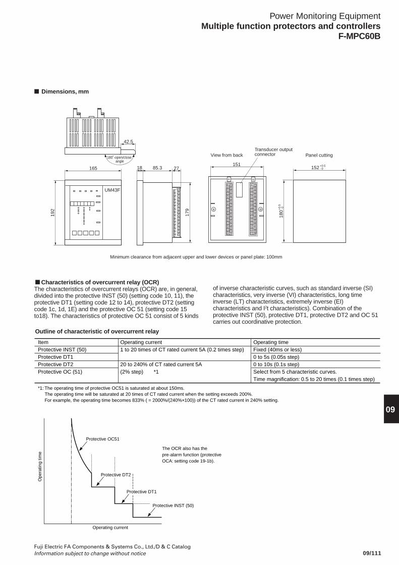
09/111Fuji Electric FA Components & Systems Co., Ltd./D & C CatalogInformation subject to change without notice
Power Monitoring EquipmentMultiple function protectors and controllers
F-MPC60B
09
Dimensions, mm
165
192
UM43F
180˚-open/close angle
42.5
Transducer output connector
Minimum clearance from adjacent upper and lower devices or panel plate: 100mm
18 85.3 152
Panel cutting
180
View from back
151
179
27+0.5- 0
+0.
5-0
A B
Characteristics of overcurrent relay (OCR)The characteristics of overcurrent relays (OCR) are, in general,divided into the protective INST (50) (setting code 10, 11), theprotective DT1 (setting code 12 to 14), protective DT2 (settingcode 1c, 1d, 1E) and the protective OC 51 (setting code 15to18). The characteristics of protective OC 51 consist of 5 kinds
ItemProtective INST (50)Protective DT1Protective DT2Protective OC (51)
*1: The operating time of protective OC51 is saturated at about 150ms.The operating time will be saturated at 20 times of CT rated current when the setting exceeds 200%.For example, the operating time becomes 833% ( = 2000%/(240%×100)) of the CT rated current in 240% setting.
Operating timeFixed (40ms or less)0 to 5s (0.05s step)0 to 10s (0.1s step)Select from 5 characteristic curves.Time magnification: 0.5 to 20 times (0.1 times step)
Operating current1 to 20 times of CT rated current 5A (0.2 times step)
20 to 240% of CT rated current 5A (2% step) *1
of inverse characteristic curves, such as standard inverse (SI)characteristics, very inverse (VI) characteristics, long timeinverse (LT) characteristics, extremely inverse (EI)characteristics and I2t characteristics). Combination of theprotective INST (50), protective DT1, protective DT2 and OC 51carries out coordinative protection.
Outline of characteristic of overcurrent relay
Protective OC51
Protective INST (50)
The OCR also has the pre-alarm function (protective OCA: setting code 19-1b).
Operating current
Ope
ratin
g tim
e
Protective DT2
Protective DT1
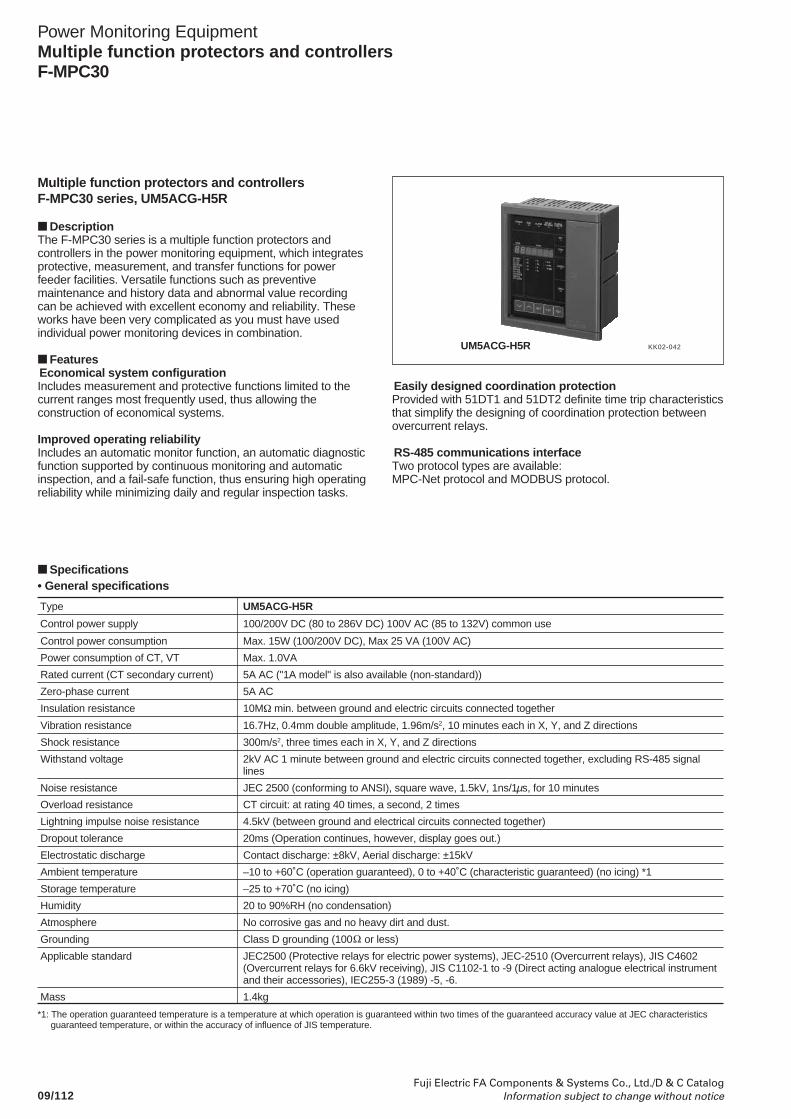
09/112Fuji Electric FA Components & Systems Co., Ltd./D & C Catalog
Information subject to change without notice
Power Monitoring EquipmentMultiple function protectors and controllersF-MPC30
Multiple function protectors and controllersF-MPC30 series, UM5ACG-H5R
DescriptionThe F-MPC30 series is a multiple function protectors andcontrollers in the power monitoring equipment, which integratesprotective, measurement, and transfer functions for powerfeeder facilities. Versatile functions such as preventivemaintenance and history data and abnormal value recordingcan be achieved with excellent economy and reliability. Theseworks have been very complicated as you must have usedindividual power monitoring devices in combination.
FeaturesEconomical system configurationIncludes measurement and protective functions limited to thecurrent ranges most frequently used, thus allowing theconstruction of economical systems.
Improved operating reliabilityIncludes an automatic monitor function, an automatic diagnosticfunction supported by continuous monitoring and automaticinspection, and a fail-safe function, thus ensuring high operatingreliability while minimizing daily and regular inspection tasks.
KK02-042UM5ACG-H5R
Easily designed coordination protectionProvided with 51DT1 and 51DT2 definite time trip characteristicsthat simplify the designing of coordination protection betweenovercurrent relays.
RS-485 communications interfaceTwo protocol types are available:MPC-Net protocol and MODBUS protocol.
Specifications• General specifications
Type UM5ACG-H5R
Control power supply 100/200V DC (80 to 286V DC) 100V AC (85 to 132V) common use
Control power consumption Max. 15W (100/200V DC), Max 25 VA (100V AC)
Power consumption of CT, VT Max. 1.0VA
Rated current (CT secondary current) 5A AC ("1A model" is also available (non-standard))
Zero-phase current 5A AC
Insulation resistance 10MΩ min. between ground and electric circuits connected together
Vibration resistance 16.7Hz, 0.4mm double amplitude, 1.96m/s2, 10 minutes each in X, Y, and Z directions
Shock resistance 300m/s2, three times each in X, Y, and Z directions
Withstand voltage 2kV AC 1 minute between ground and electric circuits connected together, excluding RS-485 signallines
Noise resistance JEC 2500 (conforming to ANSI), square wave, 1.5kV, 1ns/1µs, for 10 minutes
Overload resistance CT circuit: at rating 40 times, a second, 2 times
Lightning impulse noise resistance 4.5kV (between ground and electrical circuits connected together)
Dropout tolerance 20ms (Operation continues, however, display goes out.)
Electrostatic discharge Contact discharge: ±8kV, Aerial discharge: ±15kV
Ambient temperature –10 to +60˚C (operation guaranteed), 0 to +40˚C (characteristic guaranteed) (no icing) *1
Storage temperature –25 to +70˚C (no icing)
Humidity 20 to 90%RH (no condensation)
Atmosphere No corrosive gas and no heavy dirt and dust.
Grounding Class D grounding (100 or less)
Applicable standard JEC2500 (Protective relays for electric power systems), JEC-2510 (Overcurrent relays), JIS C4602(Overcurrent relays for 6.6kV receiving), JIS C1102-1 to -9 (Direct acting analogue electrical instrumentand their accessories), IEC255-3 (1989) -5, -6.
Mass 1.4kg
*1: The operation guaranteed temperature is a temperature at which operation is guaranteed within two times of the guaranteed accuracy value at JEC characteristicsguaranteed temperature, or within the accuracy of influence of JIS temperature.
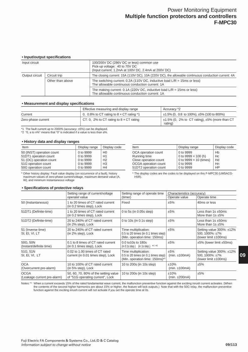
09/113Fuji Electric FA Components & Systems Co., Ltd./D & C CatalogInformation subject to change without notice
Power Monitoring EquipmentMultiple function protectors and controllers
F-MPC30
09
• Input/output specifications Input circuit 100/200V DC (286V DC or less) common use
Pick-up voltage: 40 to 70V DC(Input current; 1.2mA at 100V DC, 2.4mA at 200V DC)
Output circuit Circuit trip The closing current: 15A (110V DC), 10A (220V DC), the allowable continuous conduction current: 4A
Other than above The switching current: 0.2A (110V DC, inductive load L/R = 15ms or less)The allowable continuous conduction current: 1A
The making current: 0.1A (220V DC, inductive load L/R = 15ms or less)The allowable continuous conduction current: 1A
• Measurement and display specificationsEffective measuring and display range Accuracy *2
Current 0, 0.8% to CT rating to 8 × CT rating *1 ±1.5% (0, 0.8 to 100%), ±5% (100 to 800%)
Zero-phase current CT: 0, 2% to CT rating to 8 × CT rating ±1.5% (0, 2% to CT rating), ±5% (more than CT rating)
• History data and display ranges Item Display range Display code
50 (INST) operation count 0 to 9999 H051DT1 operation count 0 to 9999 H151 (OC) operation count 0 to 9999 H251G operation count 0 to 9999 H350G operation count 0 to 9999 H4
Item Display range Display code
OCA operation count 0 to 9999 HbRunning time 0 to 9999 × 100 (h) HcClose operation count 0 to 9999 × 10 (times) HdOCGA operation count 0 to 9999 Hn51DT2 operation count 0 to 9999 HP
* Other history display: Fault value display (on occurrence of a fault), historymaximum values of zero-phase current/voltage, maximum demand value (A,W), and minimum instantaneous voltage
*1 The fault current up to 2000% (accuracy: ±5%) can be displayed.*2 “0, a to n%” means that “0” is indicated if a value is less than a%.
• Specifications of protective relaysSetting range of current/voltage Setting range of operate time Characteristics (accuracy)operatel value (timer) Operate value Operate time
50 (Instantaneous) 1 to 20 times of CT rated current Fixed ±5% 40ms or less(in 0.2 times step), Lock
51DT1 (Definite-time) 1 to 20 times of CT rated current 0 to 5s (in 0.05s step) ±5% Less than 1s ±50ms(in 0.2 times step), Lock More than 1s ±5%
51DT2 (Definite-time) 20 to 240% of CT rated current 0 to 10s (in 0.1s step) ±5% Less than 1s ±50ms(in 2% step), Lock More than 1s ±5%
51 (Inverse time) 20 to 240% of CT rated current Time multiplication: ±5% Setting value 300%: ±12%SI, EI, VI, LT (in 2% step), Lock 0.5 to 20 times (in 0.1 times step) 500, 1000%: ±7%
(Min. operation time: 150ms) (lower limit ±100ms)
50G, 50N 0.1 to 8 times of CT rated current 0.0 to10s to 180s ±5% ±5% (lower limit ±50ms)(Instant/definite time) (in 0.1 times step), Lock (in 0.1s step.) (in 1s step.) *1 *2
51G, 51N 0.02 to 1.00 times of CT rated Time multiplication: ±5% Setting value 300%: ±12%SI, EI, VI, LT current (in 0.01 times step), Lock 0.5 to 20 times (in 0.1 times step) (min. ±100mA) 500, 1000%: ±7%
(Min. operation time: 150ms)*1 (lower limit ±100ms)
OCA 10 to 100% of CT rated current 10 to 200s (in 10s step) ±10% ±5%(Overcurrent pre-alarm) (in 5% step), Lock (min. ±100mA)
OCGA 50, 60, 70, 80% of the setting value 10 to 200s (in 10s step) ±10% ±5%(Leakage current pre-alarm) of "51G operating current", Lock (min. ±200mA)
Notes: *1 When a current exceeds 15% of the rated fundamental wave current, the malfunction preventive function against the exciting inrush current activates. (Whenthe contents of the second higher harmonics are about 15% or higher, the feature will lock outputs.) Note that with the 50G relay, the malfunction preventivefunction against the exciting inrush current will not activate if you set the operate time at 0s.
* The display codes are the codes to be displayed on this F-MPC30 (UM5ACG-H5R).
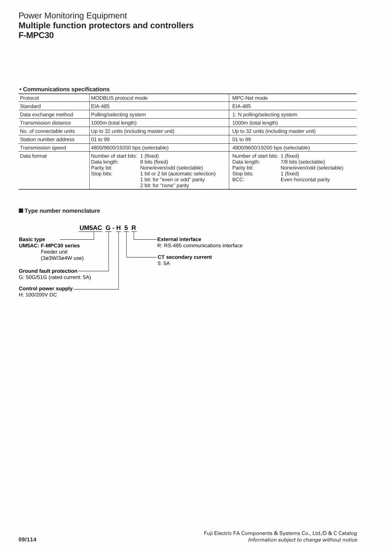
09/114Fuji Electric FA Components & Systems Co., Ltd./D & C Catalog
Information subject to change without notice
Power Monitoring EquipmentMultiple function protectors and controllersF-MPC30
• Communications specifications Protocol MODBUS protocol mode MPC-Net mode
Standard EIA-485 EIA-485
Data exchange method Polling/selecting system 1: N polling/selecting system
Transmission distance 1000m (total length) 1000m (total length)
No. of connectable units Up to 32 units (including master unit) Up to 32 units (including master unit)
Station number address 01 to 99 01 to 99
Transmission speed 4800/9600/19200 bps (selectable) 4800/9600/19200 bps (selectable)
Data format Number of start bits: 1 (fixed) Number of start bits: 1 (fixed)Data length: 8 bits (fixed) Data length: 7/8 bits (selectable)Parity bit: None/even/odd (selectable) Parity bit: None/even/odd (selectable)Stop bits: 1 bit or 2 bit (automatic selection) Stop bits: 1 (fixed)
1 bit: for "even or odd" parity BCC: Even horizontal parity2 bit: for "none" parity
External interfaceR: RS-485 communications interface
Ground fault protectionG: 50G/51G (rated current: 5A)
Control power supplyH: 100/200V DC
CT secondary current5: 5A
UM5AC G - H 5 R
Basic typeUM5AC: F-MPC30 series
Feeder unit (3ø3W/3ø4W use)
Type number nomenclature
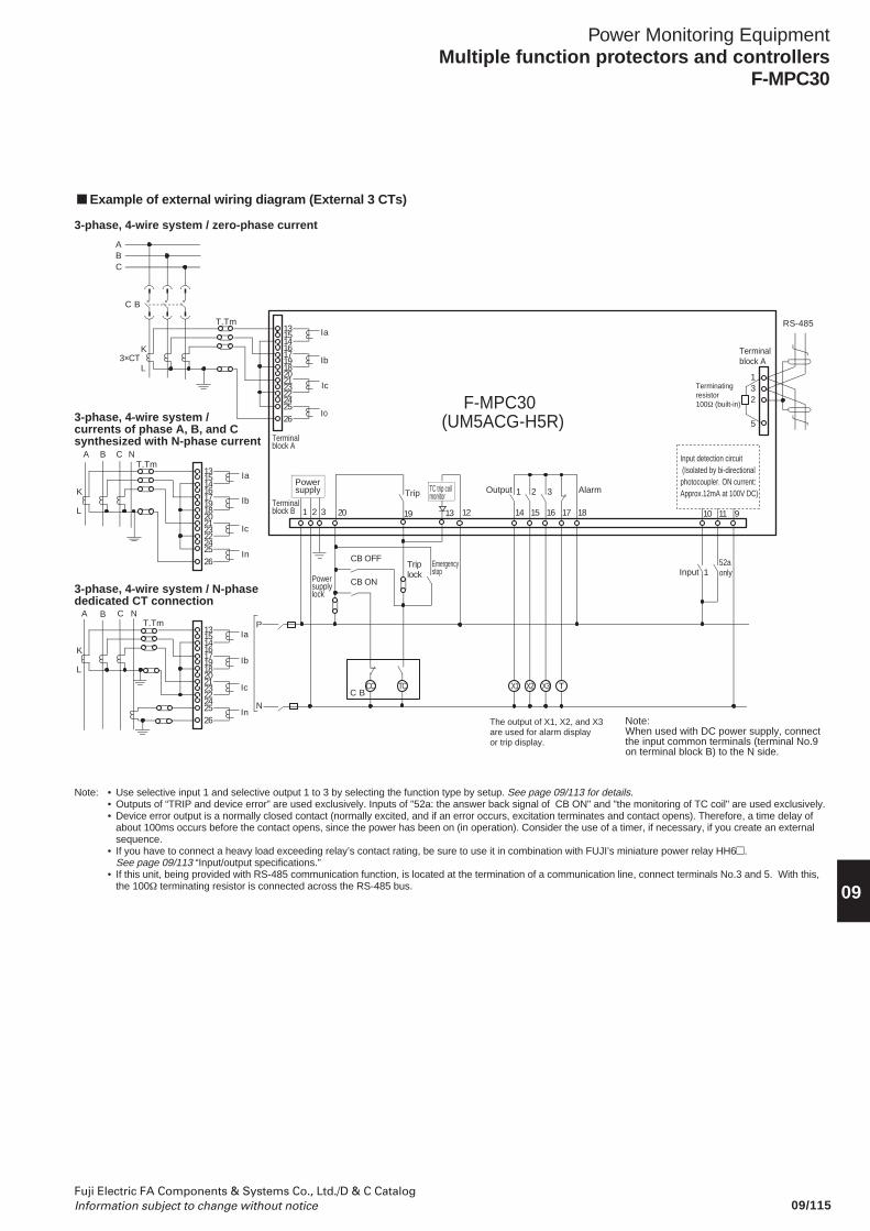
09/115Fuji Electric FA Components & Systems Co., Ltd./D & C CatalogInformation subject to change without notice
Power Monitoring EquipmentMultiple function protectors and controllers
F-MPC30
09
Example of external wiring diagram (External 3 CTs)
1 2 3
TCCC
20 19 13 12
P
N
C B
C B
ABC
14 15 16 17 18 10 11 9
X1 X2 X3 T
1
132
5
RS-48513
14
17
18
21
22
2526
3×CTK
L
T.Tm
15
16
19
20
23
24
Ia
Ib
Ic
I0
CB ON
CB OFFTriplock
K
L
T.Tm
3-phase, 4-wire system / zero-phase current
3-phase, 4-wire system / currents of phase A, B, and C synthesized with N-phase current
3-phase, 4-wire system / N-phase dedicated CT connection
K
L
T.Tm
A B NC
A B C N
Ia
Ib
Ic
In
Ia
Ib
Ic
In
Powersupplylock
Emergencystop
The output of X1, X2, and X3 are used for alarm displayor trip display.
Note:When used with DC power supply, connect the input common terminals (terminal No.9 on terminal block B) to the N side.
Terminalblock A
Terminalblock B
Powersupply Trip TC trip coil
monitor 1 2 3 AlarmOutput
Input detection circuit (Isolated by bi-directionalphotocoupler. ON current:Approx.12mA at 100V DC)
52aonlyInput
Terminatingresistor100Ω (built-in)
Terminalblock A
F-MPC30(UM5ACG-H5R)
13
14
17
18
21
22
2526
15
16
19
20
23
24
13
14
17
18
21
22
2526
15
16
19
20
23
24
Note: • Use selective input 1 and selective output 1 to 3 by selecting the function type by setup. See page 09/113 for details.• Outputs of “TRIP and device error” are used exclusively. Inputs of "52a: the answer back signal of CB ON" and "the monitoring of TC coil" are used exclusively.• Device error output is a normally closed contact (normally excited, and if an error occurs, excitation terminates and contact opens). Therefore, a time delay of
about 100ms occurs before the contact opens, since the power has been on (in operation). Consider the use of a timer, if necessary, if you create an externalsequence.
• If you have to connect a heavy load exceeding relay’s contact rating, be sure to use it in combination with FUJI’s miniature power relay HH6.See page 09/113 “Input/output specifications.”
• If this unit, being provided with RS-485 communication function, is located at the termination of a communication line, connect terminals No.3 and 5. With this,the 100Ω terminating resistor is connected across the RS-485 bus.
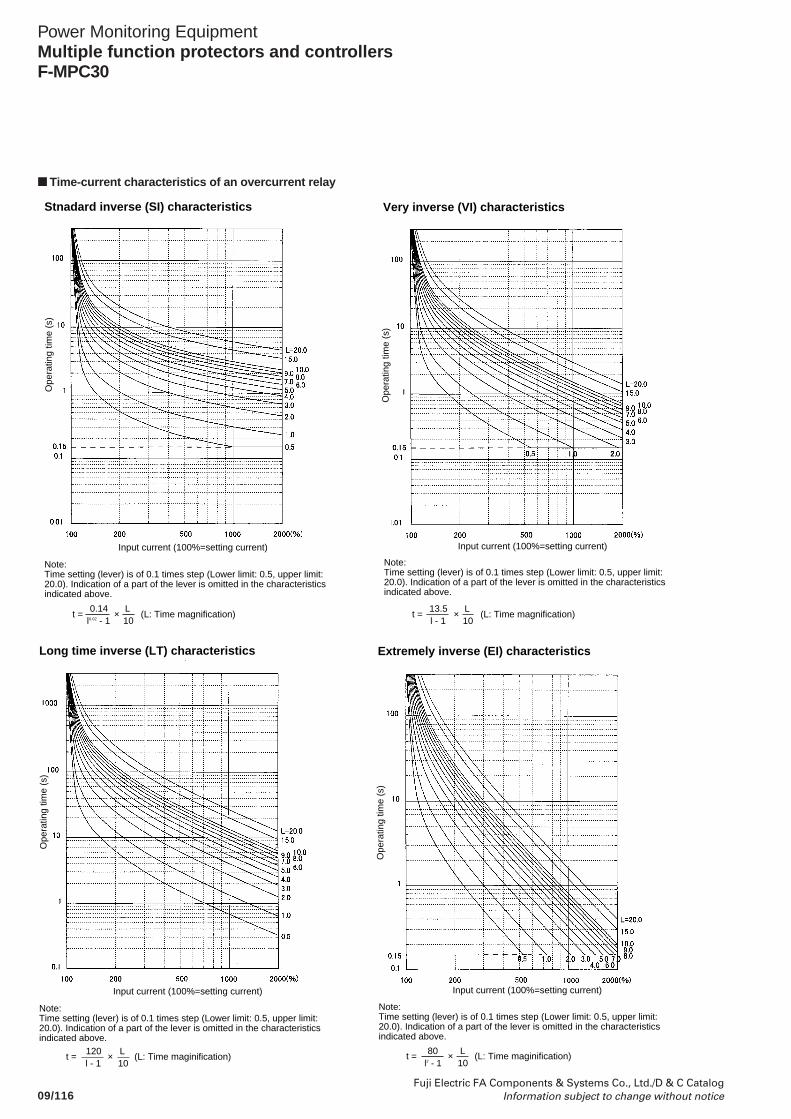
09/116Fuji Electric FA Components & Systems Co., Ltd./D & C Catalog
Information subject to change without notice
Power Monitoring EquipmentMultiple function protectors and controllersF-MPC30
Time-current characteristics of an overcurrent relay
Ope
ratin
g tim
e (s
)
Input current (100%=setting current)
Note:Time setting (lever) is of 0.1 times step (Lower limit: 0.5, upper limit: 20.0). Indication of a part of the lever is omitted in the characteristics indicated above.
l - 113.5
10L
Very inverse (VI) characteristics
Ope
ratin
g tim
e (s
)
Input current (100%=setting current)
Note:Time setting (lever) is of 0.1 times step (Lower limit: 0.5, upper limit: 20.0). Indication of a part of the lever is omitted in the characteristics indicated above.
l0.02 - 10.14
10L
Stnadard inverse (SI) characteristics
t = × (L: Time magnification) t = × (L: Time magnification)
t = × (L: Time maginification)l2 - 1 10
Extremely inverse (EI) characteristics
Ope
ratin
g tim
e (s
)
Input current (100%=setting current)
Note:Time setting (lever) is of 0.1 times step (Lower limit: 0.5, upper limit: 20.0). Indication of a part of the lever is omitted in the characteristics indicated above.
80 L
Ope
ratin
g tim
e (s
)
Input current (100%=setting current)
Note:Time setting (lever) is of 0.1 times step (Lower limit: 0.5, upper limit: 20.0). Indication of a part of the lever is omitted in the characteristics indicated above.
l - 1120
10L
Long time inverse (LT) characteristics
t = × (L: Time maginification)
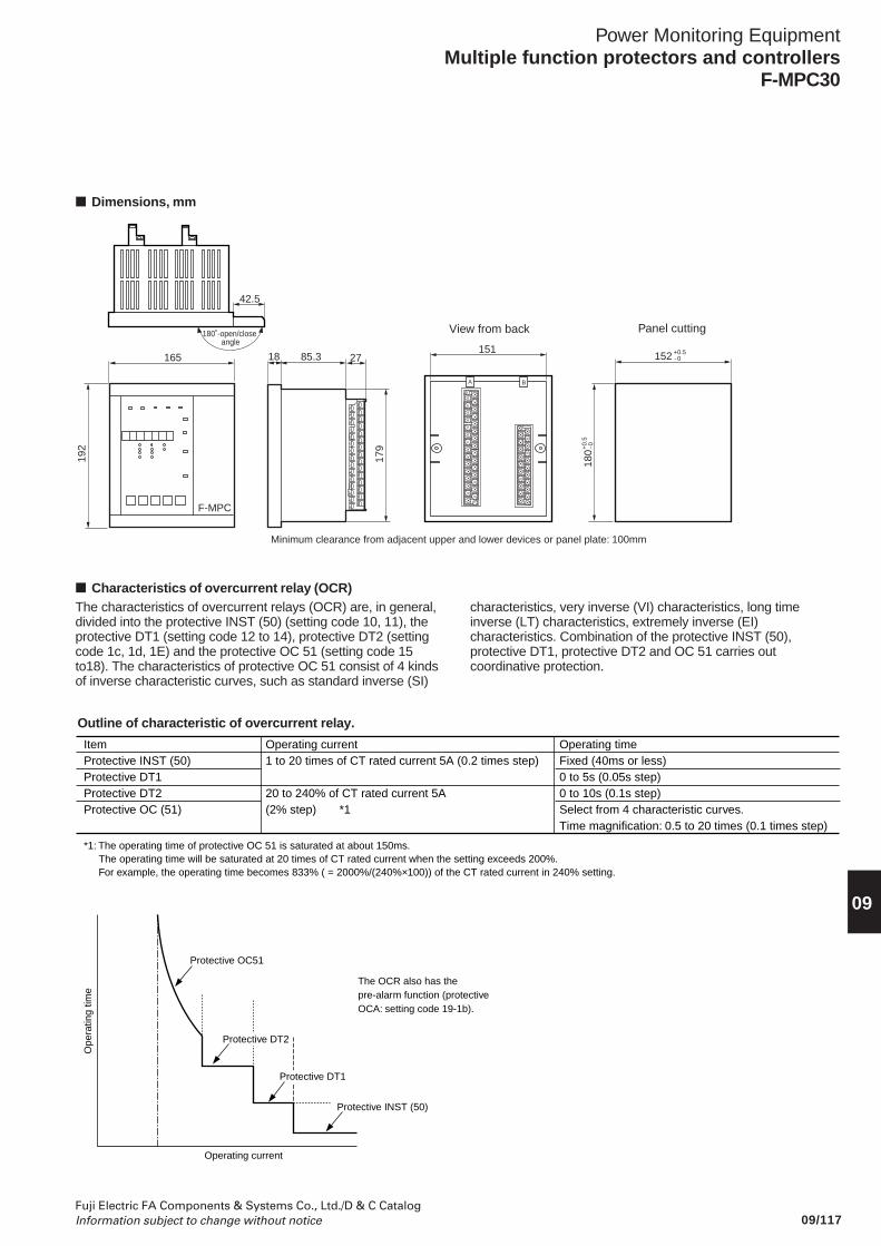
09/117Fuji Electric FA Components & Systems Co., Ltd./D & C CatalogInformation subject to change without notice
Power Monitoring EquipmentMultiple function protectors and controllers
F-MPC30
09
165
192
F-MPC
180˚-open/close angle
42.5
18 85.3 152
Panel cutting
180
Minimum clearance from adjacent upper and lower devices or panel plate: 100mm
View from back
151
179
27+0.5- 0
+0.
5-0
A B
Dimensions, mm
Characteristics of overcurrent relay (OCR)The characteristics of overcurrent relays (OCR) are, in general,divided into the protective INST (50) (setting code 10, 11), theprotective DT1 (setting code 12 to 14), protective DT2 (settingcode 1c, 1d, 1E) and the protective OC 51 (setting code 15to18). The characteristics of protective OC 51 consist of 4 kindsof inverse characteristic curves, such as standard inverse (SI)
Outline of characteristic of overcurrent relay.
Protective OC51
Protective INST (50)
The OCR also has the pre-alarm function (protective OCA: setting code 19-1b).
Operating current
Ope
ratin
g tim
e
Protective DT2
Protective DT1
characteristics, very inverse (VI) characteristics, long timeinverse (LT) characteristics, extremely inverse (EI)characteristics. Combination of the protective INST (50),protective DT1, protective DT2 and OC 51 carries outcoordinative protection.
ItemProtective INST (50)Protective DT1Protective DT2Protective OC (51)
*1: The operating time of protective OC 51 is saturated at about 150ms.The operating time will be saturated at 20 times of CT rated current when the setting exceeds 200%.For example, the operating time becomes 833% ( = 2000%/(240%×100)) of the CT rated current in 240% setting.
Operating timeFixed (40ms or less)0 to 5s (0.05s step)0 to 10s (0.1s step)Select from 4 characteristic curves.Time magnification: 0.5 to 20 times (0.1 times step)
Operating current1 to 20 times of CT rated current 5A (0.2 times step)
20 to 240% of CT rated current 5A (2% step) *1
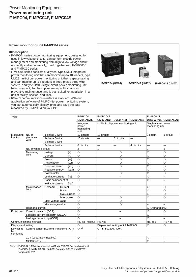
09/118Fuji Electric FA Components & Systems Co., Ltd./D & C Catalog
Information subject to change without notice
Power Monitoring EquipmentPower monitoring unitF-MPC04, F-MPC04P, F-MPC04S
Power monitoring unit F-MPC04 series
Description• F-MPC04 series power monitoring equipment, designed for
used in low voltage circuits, can perform electric powermanagement and monitoring from high to low voltage circuitefficiently and economically, used together with F-MPC60Band F-MPC30 series.
• F-MPC04 series consists of 3 types: type UM04 integratedpower monitoring unit that can monitors up to 10 feeders, typeUM02 multi-circuit power monitoring unit that is space-savingand can monitor up to 8 feeders in three-phase three-wiresystem, and type UM03 single circuit power monitoring unit,being compact, that has optimum output functions forpreventive maintenance, and is best suited for installation in aunit of facility, section, and floor.
• RS-485 communications interface is standard. With ourapplication software of F-MPC-Net power monitoring system,you can automatically display, print, and save the datameasured by F-MPC 04 on your PC.
F-MPC04P (UM02)F-MPC04 (UM04) F-MPC04S (UM03)
Measuring function
Protection
Communications interfaceDisplay and settingDevices to be connected
Type
No. of phase and wire
No. of voltage circuitMeasuring item
Maintenance item
Harmonic currentCurrent prealarm (OCA)Leakage current prealarm (OCGA)Leakage current trip (OCG)
Current sensor (Current Transformer:CT)
1-phase 2-wire1-phase 3-wire 3-phase 3-wire3-phase 4-wire
VoltageCurrentPowerActive powerReactive powerReactive energyPower-factorLeakage currentBasic component of leakage currentDemand
Max. voltage valueMin. voltage value
[V][A][W][Wh][var][varh]
[Io]
[Iob]CurrentPowerMax. currentMax. power
10 circuits10 circuits
6 circuits2
RS-485, Modbus *1
12 circuits—
—1
RS-485Display and setting unit UM02X-SCT: 5, 50, 200, 400A
—8 circuits
—
–––
–––––––
——
4 circuits
1 circuit
—1
–– (Demand only)RS-485
1 circuit
—1––
––
––RS-485
ZCT (separately installed)MCCB with ZCT
––
––
Note *1: FMPC 04 (UM04) is connected to CT via CT-BOX. For combination of F-MPC04 (UM04), CT-BOX and CT, See page 09/120 and 09/135 ; "Applicable CT."
F-MPC04UM04-ARAEIntegrated power monitoring unit
F-MPC04PUM02-AR2Multi-circuit power monitoring unit
UM02-AR3 UM02-AR4F-MPC04SUM03-ARA3GSingle-circuit power monitoring unit
UM03-ARA3
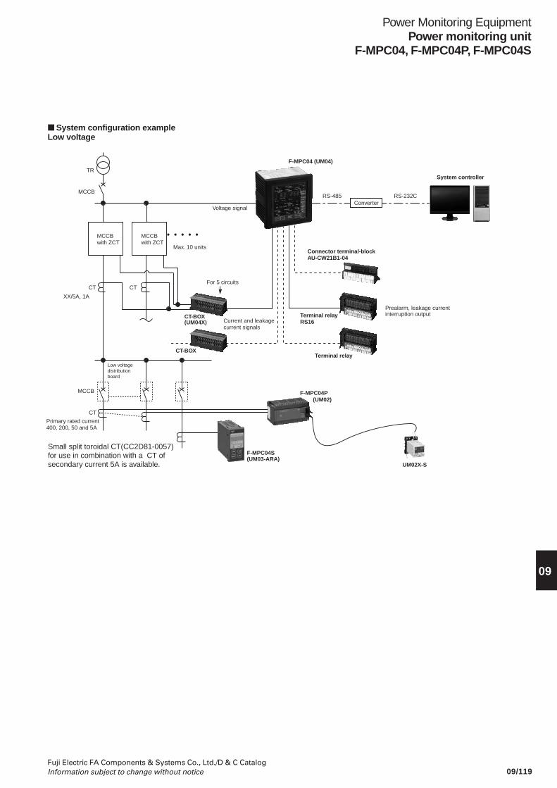
09/119Fuji Electric FA Components & Systems Co., Ltd./D & C CatalogInformation subject to change without notice
Power Monitoring EquipmentPower monitoring unit
F-MPC04, F-MPC04P, F-MPC04S
09
System configuration exampleLow voltage
TR
MCCBwith ZCT
MCCBwith ZCT
MCCB
CT
XX/5A, 1A
Primary rated current 400, 200, 50 and 5A
MCCB
CT
CT-BOX
CT-BOX(UM04X)
Terminal relayRS16
Connector terminal-blockAU-CW21B1-04
Terminal relay
F-MPC04P(UM02)
UM02X-S
CT
Max. 10 units
Low voltage distribution board
For 5 circuits
Voltage signal
Current and leakage current signals
• • • • •
F-MPC04 (UM04)
RS-485 RS-232C
Prealarm, leakage current interruption output
System controller
Small split toroidal CT(CC2D81-0057) for use in combination with a CT of secondary current 5A is available.
F-MPC04S(UM03-ARA)
Converter
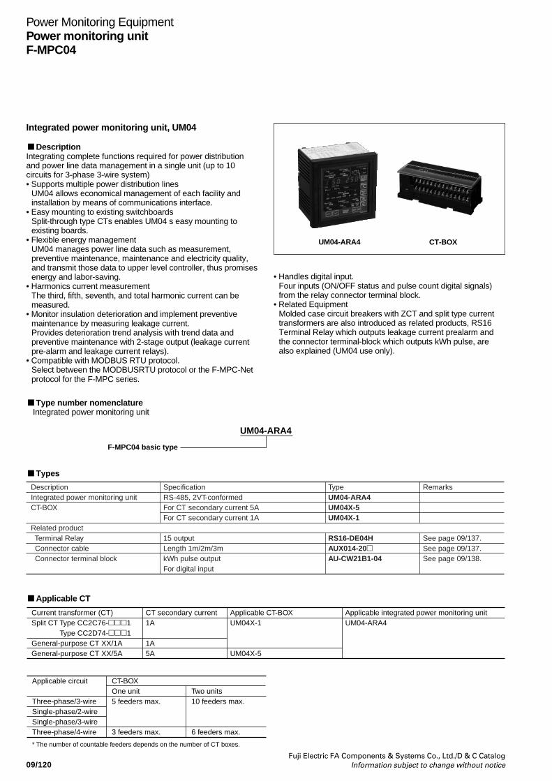
09/120Fuji Electric FA Components & Systems Co., Ltd./D & C Catalog
Information subject to change without notice
Power Monitoring EquipmentPower monitoring unitF-MPC04
UM04-ARA4 CT-BOX
UM04-ARA4
F-MPC04 basic type
Applicable CT
Types
Current transformer (CT)Split CT Type CC2C76-1 Type CC2D74-1General-purpose CT XX/1AGeneral-purpose CT XX/5A
Applicable CT-BOXUM04X-1
UM04X-5
CT secondary current1A
1A5A
Applicable integrated power monitoring unit UM04-ARA4
DescriptionIntegrated power monitoring unit CT-BOX
Related product Terminal Relay Connector cable Connector terminal block
SpecificationRS-485, 2VT-conformedFor CT secondary current 5AFor CT secondary current 1A
15 outputLength 1m/2m/3mkWh pulse outputFor digital input
TypeUM04-ARA4UM04X-5UM04X-1
RS16-DE04HAUX014-20AU-CW21B1-04
Remarks
See page 09/137.See page 09/137.See page 09/138.
Type number nomenclature Integrated power monitoring unit
Integrated power monitoring unit, UM04
DescriptionIntegrating complete functions required for power distributionand power line data management in a single unit (up to 10circuits for 3-phase 3-wire system)• Supports multiple power distribution lines
UM04 allows economical management of each facility andinstallation by means of communications interface.
• Easy mounting to existing switchboardsSplit-through type CTs enables UM04 s easy mounting toexisting boards.
• Flexible energy managementUM04 manages power line data such as measurement,preventive maintenance, maintenance and electricity quality,and transmit those data to upper level controller, thus promisesenergy and labor-saving.
• Harmonics current measurementThe third, fifth, seventh, and total harmonic current can bemeasured.
• Monitor insulation deterioration and implement preventivemaintenance by measuring leakage current.Provides deterioration trend analysis with trend data andpreventive maintenance with 2-stage output (leakage currentpre-alarm and leakage current relays).
• Compatible with MODBUS RTU protocol.Select between the MODBUSRTU protocol or the F-MPC-Netprotocol for the F-MPC series.
• Handles digital input.Four inputs (ON/OFF status and pulse count digital signals)from the relay connector terminal block.
• Related EquipmentMolded case circuit breakers with ZCT and split type currenttransformers are also introduced as related products, RS16Terminal Relay which outputs leakage current prealarm andthe connector terminal-block which outputs kWh pulse, arealso explained (UM04 use only).
Applicable circuit
Three-phase/3-wireSingle-phase/2-wireSingle-phase/3-wireThree-phase/4-wire
* The number of countable feeders depends on the number of CT boxes.
CT-BOXOne unit5 feeders max.
3 feeders max.
Two units10 feeders max.
6 feeders max.
Power Monitoring EquipmentPower monitoring unit
F-MPC04
Fuji Electric FA Components & Systems Co., Ltd./D & C CatalogInformation subject to change without notice 09/121
09
Specifications• General specificationsItem Specification
Rating Rated frequency 50 or 60Hz (Selectable by the setting)
Rated voltage Applicable to both 110V and 220V AC, 110V AC for use with a VT secondary circuit
Rated current Depends on CT-BOX specifications (5A, 1A in a CT secondary circuit, power consumption: 0.1VAmax., excluding power loss in the external cable resistance)
Zero-phase CT EW type or MCCB with a ZCT (zero-phase current transformer ) type (FUJI model)
Control power supply 85 to 264V AC (By exclusive control power supply terminal)
Inrush current 40A max., 3ms max. (AC)85A max., 3ms max. (DC)
Control power consumption *1 25VA max. (Power monitoring unit + two CT-BOXes + Terminal Relayswith all contacts ON)
Rated Voltage input 100V direct input,200V direct inputinput (VT ratio) VT primary/secondary : AC220/110V, AC440/110V, AC440/220V, AC240/110V, AC400/110V, AC3.3k/110V, AC6.6k/110V
Current input Primary rating setting : 10A, 15A, 20A, 25A, 30A, 40A, 50A, 60A, 75A, 80A, 100A, 120A, 150A, 160A, 200A, 250A, 300A, 320A, 400A, 500A, 600A(CT ratio) 630A, 750A, 800A, 100A, 1200A, 1250A, 1500A, 1600A, 2000A, 2500A, 3000A, 3150A, 3200A, 4000A, 5000A, 6000A, 7500A
Ambient temperature -10 to + 55˚C (no icing or no condensation)
Storage temperature -20 to + 70˚C (no icing or no condensation)
Humidity 20 to 90% RH (no condensation)
Atmosphere No corrosive gas and no heavy dirt and dust
Alarm and shutdown outputs Continuous output current: 1A max. (with output of terminal relay, RS16-DE04H)Make and break current: 250V AC 5A, 30V DC 5A max.
Insulation resistance 10MΩ min.: between ground and electric circuits connected together5MΩ min.: between electric circuits, between contacts
Dielectric strength 2000V AC, 1 minute between ground and electric circuits connected together, excludingT-link and RS-485 signal circuits
Impulse 4.5kV (1.2 × 50µs) between ground and electric circuits connected together, excludingT-link and RS-485 signal circuits
Momentary overload capability 20 times rated current, nine times for 0.5s, once for 2s
Shock resistance Approx. 300m/s2, three times in each of X, Y, and Z axes
Noise immunity 1 to 1.5MHz damped oscillation noise having 2.5 to 3kV peak voltage for 2s1.5kV square wave (rise time: 1ns, pulse width: 1µs) for 10 minutes continuously
Vibration resistance JIS C 60068-2-6 10-58Hz: single amplitude 0.075mm. 58-150Hz=constant accelation 10m/s2 X, Y, Zdirections 8minutes X10 cycles
Electrostatic noise resistance Mounting steel panel surface: ± 8kVF-MPC04 (UM04) front panel surface: ± 15kV
Permissible momentary power failure 20ms, continuous operation (excluding display)
Mass Power monitoring unit UM01: 1000g, CT-BOX: 300gTerminal relay: 200g
Note *1 The control power consumption on the table applies to where CT-BOXes and Terminal relays are connected to the power monitoring unit UM04.
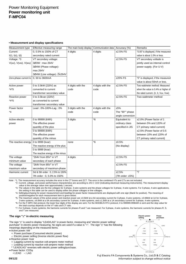
09/122Fuji Electric FA Components & Systems Co., Ltd./D & C Catalog
Information subject to change without notice
Power Monitoring EquipmentPower monitoring unitF-MPC04
• Measurement and display specifications
The sign "±" in electric measuring
The sign “±" is used to display "LEAD/LAG" in power-factor, measuring and “electric power selling/purchase” in electric power measuring. No signs are used if a value is "+". The sign “±" has the followingmeanings depending on the measured items.• Active power: kW +: Power purchase (Consumed electric power) –: Electric power selling (Inverse electric power flow)• Reactive power: kvar +: Lagging current by reactive volt-ampere meter method –: Leading current by reactive volt-ampere meter method * “LEAD/LAG” reverses with electric power selling/purchase.• Power factor: COSφ +:LEAD –: LAG
Electric powerselling
Powerpurchase
90° (COSφ=0)
270° (COSφ=0)
180°(COSφ=-1)
0°(COSφ=1)
LAG LEAD
LEAD LAG
– kW
– kvar
COSφ
kW
– kvar
–COSφ
– kW
kvar
–COSφ
kW
kvar
COSφ
Measurement type
Current:
I(r), I(s), I(t)
Voltage: *3
V(uv), V(vw), V(wu)
Zero-phase current Io
Active power
*4*5
Reactive power
*4*5
Power factor
*4
Active electric
power
The reactive energy
The voltage
minimum value
The voltage
maximum value
Harmonic current
Effective measuring range
0, 0.5% to 150% of CT
secondary rated current
VT secondary voltage:
3Ø3W : max 264V
3Ø4W (Phase voltage):
max.264V
3Ø4W (Line voltage): 3x264V
0, 50 to 3600mA
0 to 3.5kW (220V) as
converted to current
transformer secondary value
0 to 3.5kvar (220V)
as converted to current
transformer secondary value
Lead : 0%-100%-Lag : 0%
0 to 99999 (kWh)
The effective power
quantity of the plus
0 to 99999 (kWh)
The effective power
quantity of the minus
0 to 9999 (kvar)
The reactive energy of the plus
0 to 9999 (kvar)
The reactive energy of the minus
"264V from 85V" in VT
secondary of each phase
"264V from 85V" in VT
secondary of maximun-phase
3rd & 5th order : 0, 2.5% to 150%
7th order : 0, 5.0% to 150%
The main body display
4 digits
4 digits with the
code
3 digits with the
code
5 digits
none
4 digits
Communication data
4 digits
4 digits with the
code
4 digits with the
code
*6
*6
Accuracy (%)
±2.5% FS
±2.5% FS
±20% FS
±2.5% FS
±2.5% FS
±5%
The "90°" phase
angle conversion
Equivalent to
ordinary class
specified in JIS
±0.5%
(No display)
±2.5% FS
±2.5% FS
±2.5%
(7th order: ±5%)
Remarks
"0.00" is displayed, if the measured
value is about 1.0% or less.
VT secondary voltade is
jointly used as internal control
power supply. (For U-V)
"0" is displayed, if the measured
value is about 50mA or less.
Two-wattmeter method: Measured
when the value is 0.4% or higher of
the rated current. (Ir, It, Vuv, Vvw)
Two-wattmeter method
±2.0% (Power factor of 1
between 5% and 120% of
CT primary rated current)
±2.5% (Power factor of 0.5
between 10% and 120% of
CT primary rated current)
*7
Note : *1. The measurement accuracy includes the error in the CT boxes and ZCT. The error in the combined VTs and CTs are not included.*2. Current, voltage, and power performance characteristics are according to JIS C 1102 (indicating electrical measuring instruments). The measurement display
value is the average value over approximately 1 second.*3. The values in the table are the line voltages for 3-phase, 3-wire systems and the phase voltages for 3-phase, 4-wire systems. For 3-phase, 4-wire applications,
the setting in this table can be used to display either the phase voltages or line voltages.*4. Selling/purchasing for power measurement and lead/lag for power factor measurements are displayed with one sign (blank for positive). The meaning of
positive/negative for each measurement item is given below.*5. The maximum values of the active power and reactive power are ±3.5kW at a 5A secondary current for 3-phase, 3-wire systems, ±0.69kW at 1A for 3-phase,
3-wire systems, ±6.0kW at a 5A secondary current for 3-phase, 4-wire systems, and ±1.2kW at a 1A secondary current for 3-phase, 4-wire systems.*6. For the F-MPC-Net protocol, the lower four digits of the display are sent. For the MODBUS RTU protocol, 0 to 999999.999kWh is sent and the step value for
the total countup depends on the VT ratio and CT ratio.*7. For 3-phase, 3-wire systems, the harmonic currents for phases R and T are measured. For 3-phase, 4-wire systems, the harmonic currents for phases R, S,
and T are measured.
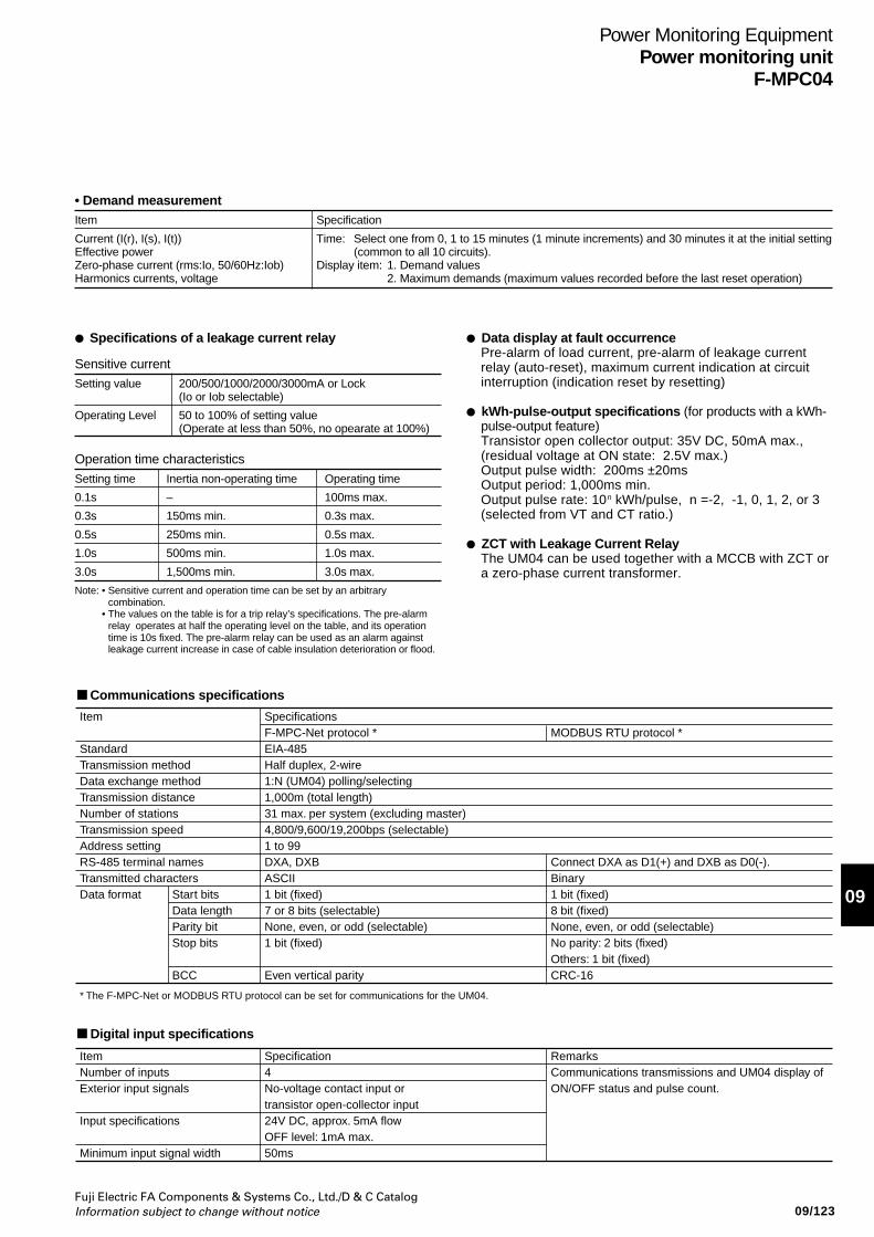
Power Monitoring EquipmentPower monitoring unit
F-MPC04
Fuji Electric FA Components & Systems Co., Ltd./D & C CatalogInformation subject to change without notice 09/123
09
• Demand measurementItem Specification
Current (I(r), I(s), I(t)) Time: Select one from 0, 1 to 15 minutes (1 minute increments) and 30 minutes it at the initial settingEffective power (common to all 10 circuits).Zero-phase current (rms:Io, 50/60Hz:Iob) Display item: 1. Demand valuesHarmonics currents, voltage 2. Maximum demands (maximum values recorded before the last reset operation)
Operation time characteristics
Setting time Inertia non-operating time Operating time
0.1s – 100ms max.
0.3s 150ms min. 0.3s max.
0.5s 250ms min. 0.5s max.
1.0s 500ms min. 1.0s max.
3.0s 1,500ms min. 3.0s max.
Specifications of a leakage current relay Data display at fault occurrencePre-alarm of load current, pre-alarm of leakage currentrelay (auto-reset), maximum current indication at circuitinterruption (indication reset by resetting)
kWh-pulse-output specifications (for products with a kWh-pulse-output feature)Transistor open collector output: 35V DC, 50mA max.,(residual voltage at ON state: 2.5V max.)Output pulse width: 200ms ±20msOutput period: 1,000ms min.Output pulse rate: 10n kWh/pulse, n =-2, -1, 0, 1, 2, or 3(selected from VT and CT ratio.)
ZCT with Leakage Current RelayThe UM04 can be used together with a MCCB with ZCT ora zero-phase current transformer.
Note: • Sensitive current and operation time can be set by an arbitrarycombination.
• The values on the table is for a trip relay’s specifications. The pre-alarmrelay operates at half the operating level on the table, and its operationtime is 10s fixed. The pre-alarm relay can be used as an alarm againstleakage current increase in case of cable insulation deterioration or flood.
Communications specifications
Item
StandardTransmission methodData exchange methodTransmission distanceNumber of stationsTransmission speedAddress settingRS-485 terminal namesTransmitted charactersData format
* The F-MPC-Net or MODBUS RTU protocol can be set for communications for the UM04.
SpecificationsF-MPC-Net protocol *EIA-485Half duplex, 2-wire1:N (UM04) polling/selecting1,000m (total length)31 max. per system (excluding master)4,800/9,600/19,200bps (selectable)1 to 99DXA, DXBASCII1 bit (fixed)7 or 8 bits (selectable)None, even, or odd (selectable)1 bit (fixed)
Even vertical parity
MODBUS RTU protocol *
Connect DXA as D1(+) and DXB as D0(-).Binary1 bit (fixed)8 bit (fixed)None, even, or odd (selectable)No parity: 2 bits (fixed)Others: 1 bit (fixed)CRC-16
Start bitsData lengthParity bitStop bits
BCC
Sensitive currentSetting value 200/500/1000/2000/3000mA or Lock
(Io or Iob selectable)
Operating Level 50 to 100% of setting value(Operate at less than 50%, no opearate at 100%)
Digital input specifications
ItemNumber of inputsExterior input signals
Input specifications
Minimum input signal width
Specification4No-voltage contact input or transistor open-collector input24V DC, approx. 5mA flowOFF level: 1mA max.50ms
RemarksCommunications transmissions and UM04 display of ON/OFF status and pulse count.
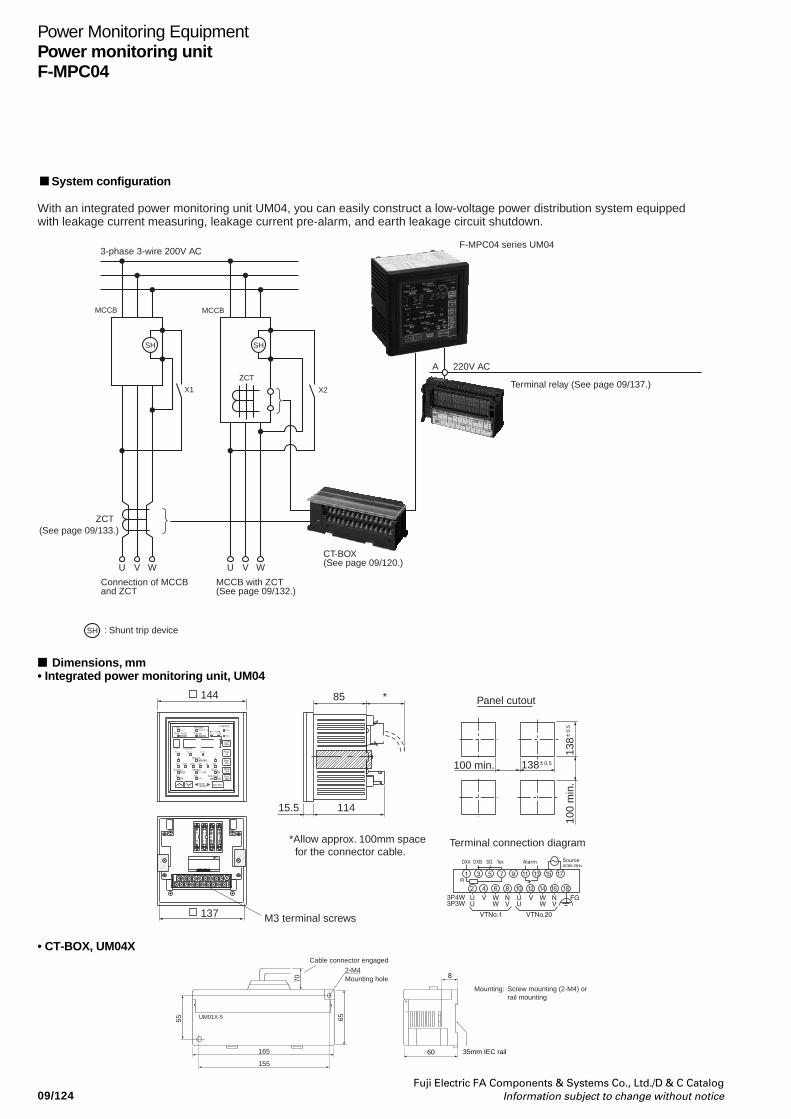
09/124Fuji Electric FA Components & Systems Co., Ltd./D & C Catalog
Information subject to change without notice
Power Monitoring EquipmentPower monitoring unitF-MPC04
SH
U WV U WV
SH
SH
A
MCCB
ZCT(See page 09/133.)
MCCB
ZCT220V AC
3-phase 3-wire 200V ACF-MPC04 series UM04
Terminal relay (See page 09/137.)
: Shunt trip device
X1 X2
With an integrated power monitoring unit UM04, you can easily construct a low-voltage power distribution system equipped with leakage current measuring, leakage current pre-alarm, and earth leakage circuit shutdown.
Connection of MCCB and ZCT
MCCB with ZCT (See page 09/132.)
CT-BOX (See page 09/120.)
System configuration
• CT-BOX, UM04X
8
60
155
165
Cable connector engaged
65
70
55 UM01X-5
2-M4
35mm IEC rail
Mounting holeMounting: Screw mounting (2-M4) or
rail mounting
Dimensions, mm• Integrated power monitoring unit, UM04
144
15.5
M3 terminal screws
*Allow approx. 100mm space for the connector cable.
114
85
0.5
138
0.5138
Panel cutout
Terminal connection diagram
*
100 min.
100
min
.
137
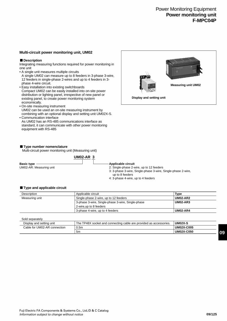
Fuji Electric FA Components & Systems Co., Ltd./D & C CatalogInformation subject to change without notice
Power Monitoring EquipmentPower monitoring unit
F-MPC04P
09/125
09
Multi-circuit power monitoring unit, UM02
DescriptionIntegrating measuring functions required for power monitoring inone unit• A single unit measures multiple circuits
A single UM02 can measure up to 8 feeders in 3-phase 3-wire,12 feeders in single-phase 2-wires and up to 4 feeders in 3-phase 4-wire circuit.
• Easy installation into existing switchboardsCompact UM02 can be easily installed into on-site powerdistribution or lighting panel, irrespective of new panel orexisting panel, to create power monitoring systemeconomically.
• On-site measuring instrumentUM02 can be used an on-site measuring instrument bycombining with an optional display and setting unit UM02X-S.
• Communication interfaceAs UM02 has an RS-485 communications interface asstandard, it can communicate with other power monitoringequipment with RS-485
Display and setting unit
Measuring unit UM02
Type number nomenclature Multi-circuit power monitoring unit (Measuring unit)
Type and applicable circuit
Applicable circuit2: Single-phase 2-wire, up to 12 feeders3: 3-phase 3-wire, Single-phase 3-wire, Single-phase 2-wire,
up to 8 feeders4: 3-phase 4-wire, up to 4 feeders
UM02-AR 3
Basic typeUM02-AR: Measuring unit
DescriptionMeasuring unit
Sold separately Display and setting unit Cable for UM02-AR connection
Applicable circuitSingle-phase 2-wire, up to 12 feeders3-phase 3-wire, Single-phase 3-wire, Single-phase 2-wire,up to 8 feeders3-phase 4-wire, up to 4 feeders
The TP48X socket and connecting cable are provided as accessories.0.5m5m
TypeUM02-AR2UM02-AR3
UM02-AR4
UM02X-SUM02X-C005UM02X-C050
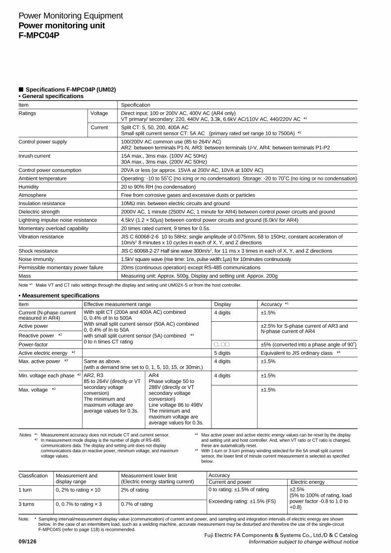
09/126Fuji Electric FA Components & Systems Co., Ltd./D & C Catalog
Information subject to change without notice
Power Monitoring EquipmentPower monitoring unitF-MPC04P
Specifications F-MPC04P (UM02)• General specificationsItem Specification
Ratings Voltage Direct input: 100 or 200V AC, 400V AC (AR4 only)VT primary/ secondary: 220, 440V AC, 3.3k, 6.6kV AC/110V AC, 440/220V AC *1
Current Split CT: 5, 50, 200, 400A ACSmall split current sensor CT: 5A AC (primary rated set range 10 to 7500A) *1
Control power supply 100/200V AC common use (85 to 264V AC)AR2: between terminals P1-N, AR3: between terminals U-V, AR4: between terminals P1-P2
Inrush current 15A max., 3ms max. (100V AC 50Hz)30A max., 3ms max. (200V AC 50Hz)
Control power consumption 20VA or less (or approx. 15VA at 200V AC, 10VA at 100V AC)
Ambient temperature Operating: -10 to 55˚C (no icing or no condensation) Storage: -20 to 70˚C (no icing or no condensation)
Humidity 20 to 90% RH (no condensation)
Atmosphere Free from corrosive gases and excessive dusts or particles
Insulation resistance 10MΩ min. between electric circuits and ground
Dielectric strength 2000V AC, 1 minute (2500V AC, 1 minute for AR4) between control power circuits and ground
Lightning impulse noise resistance 4.5kV (1.2 × 50µs) between control power circuits and ground (6.0kV for AR4)
Momentary overload capability 20 times rated current, 9 times for 0.5s.
Vibration resistance JIS C 60068-2-6 10 to 58Hz: single amplitude of 0.075mm, 58 to 150Hz, constant acceleration of10m/s2 8 minutes x 10 cycles in each of X, Y, and Z directions
Shock resistance JIS C 60068-2-27 Half sine wave 300m/s2, for 11 ms x 3 times in each of X, Y, and Z directions
Noise immunity 1.5kV square wave (rise time: 1ns, pulse width:1µs) for 10minutes continuously
Permissible momentary power failure 20ms (continuous operation) except RS-485 communications
Mass Measuring unit: Approx. 500g, Display and setting unit: Approx. 200g
Note *1 Make VT and CT ratio settings through the display and seting unit UM02X-S or from the host controller.
• Measurement specificationsItem Effective measurement range Display Accuracy *1
Current (N-phase current 4 digits ±1.5%measured in AR4)
Active power ±2.5% for S-phase current of AR3 andN-phase current of AR4
Reactive power *2
Power-factor . ±5% (converted into a phase angle of 90˚)
Active electric energy *2 5 digits Equivalent to JIS ordinary class *4
Max. active power *3 Same as above. 4 digits ±1.5%(with a demand time set to 0, 1, 5, 10, 15, or 30min.)
Min. voltage each phase *2 4 digits ±1.5%
Max. voltage *2 ±1.5%
With split CT (200A and 400A AC) combined0, 0.4% of In to 500AWith small split current sensor (50A AC) combined0, 0.4% of In to 50Awith small split current sensor (5A) combined *4
0 to n times CT rating
Notes *1 Measurement accuracy does not include CT and current sensor.*2 In measurement mode display is the number of digits of RS-485
communications data. The display and setting unit does not displaycommunications data on reactive power, minimum voltage, and maximumvoltage values.
AR2, R385 to 264V (directly or VTsecondary voltageconversion)The minimum andmaximum voltage areaverage values for 0.3s.
AR4Phase voltage 50 to288V (directly or VTsecondary voltageconversion)Line voltage 86 to 498VThe minimum andmaximum voltage areaverage values for 0.3s.
Classfication Measurement and Measurement lower limit Accuracydisplay range (Electric energy starting current) Current and power Electric energy
1 turn 0, 2% to rating × 10 2% of rating
3 turns 0, 0.7% to rating × 3 0.7% of rating
±2.5%(5% to 100% of rating, loadpower factor -0.8 to 1.0 to+0.8)
0 to rating: ±1.5% of rating
Exceeding rating: ±1.5% (FS)
Note: *
*3 Max active power and active electric energy values can be reset by the displayand setting unit and host controller. And, when VT ratio or CT ratio is changed,these are autamalically reset.
*4 With 1-turn or 3-turn primary winding selected for the 5A small split currentsensor, the lower limit of minute current measurement is selected as specifiedbelow.
Sampling interval/measurement display value (communication) of current and power, and sampling and integration intervals of electric energy are shownbelow. In the case of an intermittent load, such as a welding machine, accurate measurement may be disturbed and therefore the use of the single-circuitF-MPC04S (refer to page 118) is recommended.
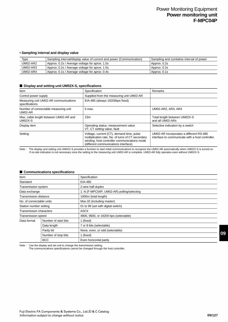
Fuji Electric FA Components & Systems Co., Ltd./D & C CatalogInformation subject to change without notice
Power Monitoring EquipmentPower monitoring unit
F-MPC04P
09/127
09
Display and setting unit UM02X-S, specificationsItem Specification Remarks
Control power supply Supplied from the measuring unit UM02-AR
Measuring unit UM02-AR communications EIA-485 (always 19200bps fixed)specifications
Number of connectable measuring unit 5 max. UM02-AR2, AR3, AR4UM02-AR
Max. cable length between UM02-AR and 23m Total length between UM02X-SUM02X-S and all UM02-ARs
Display item Operating status, measurement value Selective indication by a switchVT, CT setting value, fault
Setting Voltage, current (CT), demand time, pulse UM02-AR incorporates a different RS-485multiplication rate, No. of turns of CT secondary interface to communicate with a host controller.winding, host controller communications mode(different communications interface)
Note : The display and setting unit UM02X-S provides a function to start initial communications to recognize the UM02-AR automatically when UM02X-S is turned on. If on-site indication is not necessary once the setting to the measuring unit UM02-AR is complete, UM02-AR fully operates even without UM02X-S.
Communications specificationsItem Specification
Standard EIA-485
Transmission system 2-wire half duplex
Data exchange 1: N (F-MPC04P, UM02-AR) polling/selecting
Transmission distance 1000m (total length)
No. of connectable units Max.32 (including master)
Station number setting 01 to 99 (set with digital switch)
Transmission characters ASCII
Transmission speed 4800, 9600, or 19200 bps (selectable)
Data format Number of start bits 1 (fixed)
Data length 7 or 8 bits (selectable)
Parity bit None, even, or odd (selectable)
Number of stop bits 1 (fixed)
BCC Even horizontal parity
Note : Use the display and set unit to change the transmission setting. The communications specifications cannot be changed through the host controller.
TypeUM02-AR2UM02-AR3UM02-AR4
Sampling and cumlative interval of powerApprox. 0.2sApprox. 0.2sApprox. 0.1s
Sampling interval/display value of current and power (Communication)Approx. 0.2s / Average voltage for aprox. 1.5sApprox. 0.2s / Average voltage for aprox. 1.5sApprox. 0.1s / Average voltage for aprox. 0.4s
• Sampling interval and display value
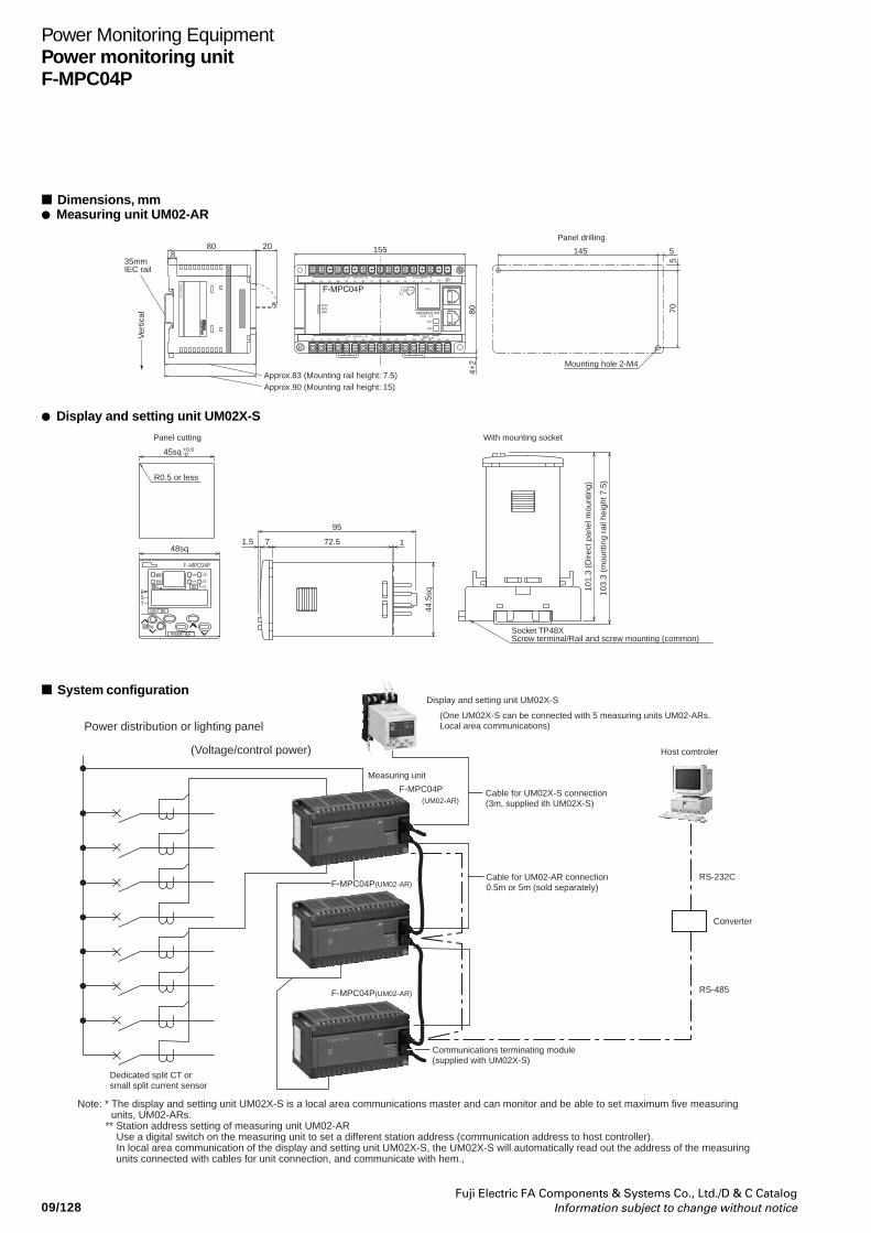
09/128Fuji Electric FA Components & Systems Co., Ltd./D & C Catalog
Information subject to change without notice
Power Monitoring EquipmentPower monitoring unitF-MPC04P
Dimensions, mm Measuring unit UM02-AR
Display and setting unit UM02X-S
(Voltage/control power)
Power distribution or lighting panel
Dedicated split CT or small split current sensor
Display and setting unit UM02X-S
(One UM02X-S can be connected with 5 measuring units UM02-ARs.Local area communications)
F-MPC04P(UM02-AR)
Measuring unit
RS-232C
Converter
RS-485F-MPC04P(UM02-AR)
F-MPC04PF-MPC04P(UM02-AR)(UM02-AR)
Cable for UM02X-S connection(3m, supplied ith UM02X-S)
Cable for UM02-AR connection0.5m or 5m (sold separately)
Communications terminating module(supplied with UM02X-S)
Note: * The display and setting unit UM02X-S is a local area communications master and can monitor and be able to set maximum five measuring units, UM02-ARs.
** Station address setting of measuring unit UM02-ARUse a digital switch on the measuring unit to set a different station address (communication address to host controller).In local area communication of the display and setting unit UM02X-S, the UM02X-S will automatically read out the address of the measuring units connected with cables for unit connection, and communicate with hem.,
F-MPC04P(UM02-AR)
Host comtroler
System configuration
880
Approx.83 (Mounting rail height: 7.5)Approx.90 (Mounting rail height: 15)
Ver
tical
35mmIEC rail
20145 5
570
155
Panel drilling
Panel cutting With mounting socket
Mounting hole 2-M4
4+2
103.
3 (m
ount
ing
rail
heig
ht 7
.5)
101.
3 (D
irect
pan
el m
ount
ing)
Socket TP48XScrew terminal/Rail and screw mounting (common)
44.5
sq
1
95
72.571.5
-0+0.645sq
R0.5 or less
48sq
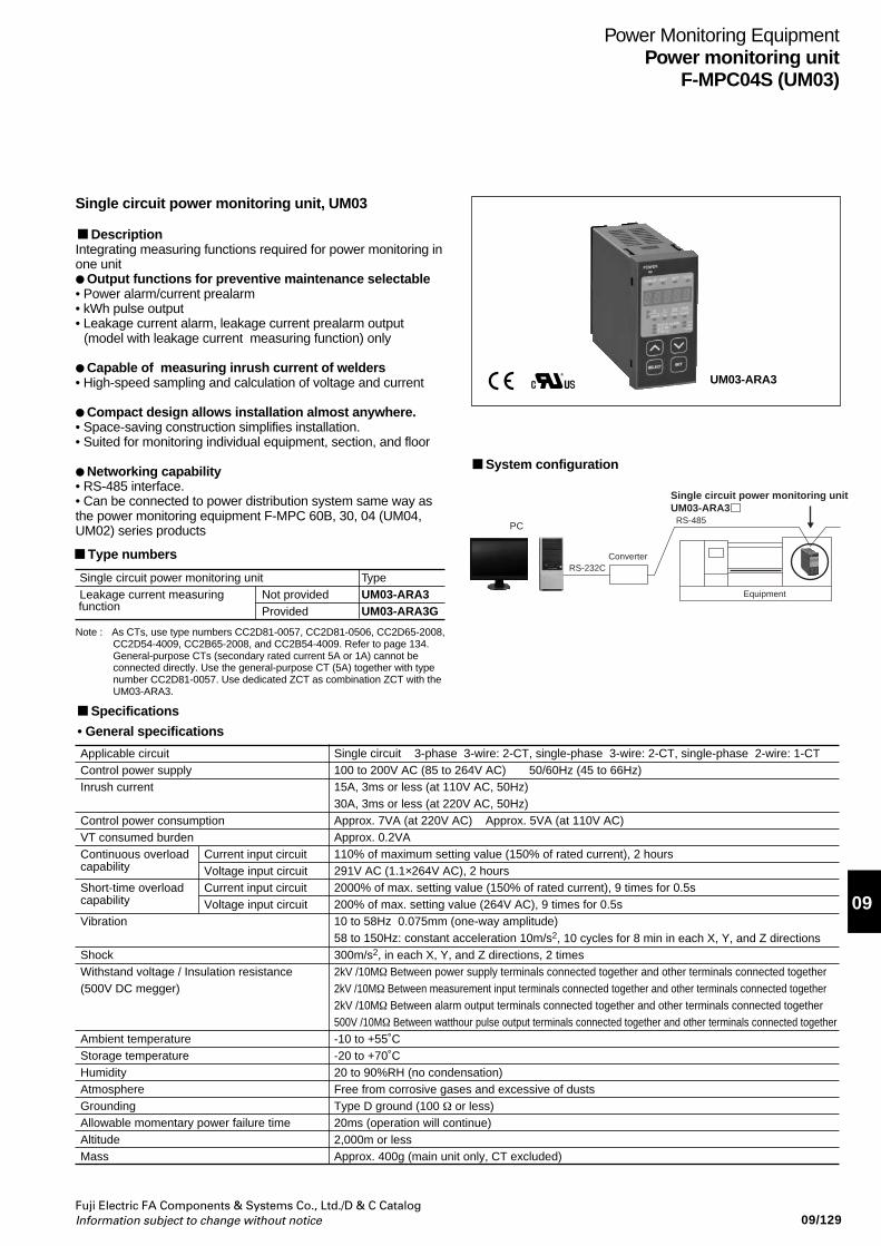
Fuji Electric FA Components & Systems Co., Ltd./D & C CatalogInformation subject to change without notice
Power Monitoring EquipmentPower monitoring unit
F-MPC04S (UM03)
09/129
09
UM03-ARA3
Single circuit power monitoring unit, UM03
DescriptionIntegrating measuring functions required for power monitoring inone unit Output functions for preventive maintenance selectable• Power alarm/current prealarm• kWh pulse output• Leakage current alarm, leakage current prealarm output
(model with leakage current measuring function) only
Capable of measuring inrush current of welders• High-speed sampling and calculation of voltage and current
Compact design allows installation almost anywhere.• Space-saving construction simplifies installation.• Suited for monitoring individual equipment, section, and floor
Networking capability• RS-485 interface.• Can be connected to power distribution system same way asthe power monitoring equipment F-MPC 60B, 30, 04 (UM04,UM02) series products
Type numbers
System configuration
Single circuit power monitoring unitLeakage current measuring
functionNot providedProvided
TypeUM03-ARA3UM03-ARA3G
PC
RS-232CConverter
RS-485
Single circuit power monitoring unitUM03-ARA3
Equipment
Specifications
• General specifications
Applicable circuitControl power supplyInrush current
Control power consumptionVT consumed burdenContinuous overloadcapability
Short-time overload capability
Vibration
ShockWithstand voltage / Insulation resistance(500V DC megger)
Ambient temperatureStorage temperatureHumidityAtmosphereGroundingAllowable momentary power failure timeAltitudeMass
Current input circuitVoltage input circuitCurrent input circuitVoltage input circuit
Single circuit 3-phase 3-wire: 2-CT, single-phase 3-wire: 2-CT, single-phase 2-wire: 1-CT100 to 200V AC (85 to 264V AC) 50/60Hz (45 to 66Hz)15A, 3ms or less (at 110V AC, 50Hz)30A, 3ms or less (at 220V AC, 50Hz)Approx. 7VA (at 220V AC) Approx. 5VA (at 110V AC)Approx. 0.2VA110% of maximum setting value (150% of rated current), 2 hours291V AC (1.1×264V AC), 2 hours2000% of max. setting value (150% of rated current), 9 times for 0.5s200% of max. setting value (264V AC), 9 times for 0.5s10 to 58Hz 0.075mm (one-way amplitude) 58 to 150Hz: constant acceleration 10m/s2, 10 cycles for 8 min in each X, Y, and Z directions300m/s2, in each X, Y, and Z directions, 2 times2kV /10MΩ Between power supply terminals connected together and other terminals connected together2kV /10MΩ Between measurement input terminals connected together and other terminals connected together2kV /10MΩ Between alarm output terminals connected together and other terminals connected together500V /10MΩ Between watthour pulse output terminals connected together and other terminals connected together-10 to +55˚C-20 to +70˚C20 to 90%RH (no condensation)Free from corrosive gases and excessive of dustsType D ground (100 Ω or less)20ms (operation will continue)2,000m or lessApprox. 400g (main unit only, CT excluded)
Note : As CTs, use type numbers CC2D81-0057, CC2D81-0506, CC2D65-2008,CC2D54-4009, CC2B65-2008, and CC2B54-4009. Refer to page 134.General-purpose CTs (secondary rated current 5A or 1A) cannot beconnected directly. Use the general-purpose CT (5A) together with typenumber CC2D81-0057. Use dedicated ZCT as combination ZCT with theUM03-ARA3.
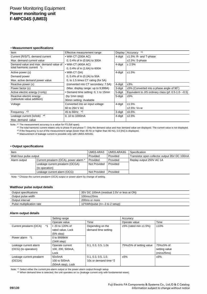
09/130Fuji Electric FA Components & Systems Co., Ltd./D & C Catalog
Information subject to change without notice
Power Monitoring EquipmentPower monitoring unitF-MPC04S (UM03)
Current prealarm (OCA) *1
Power alarm *1
Leakage current alarm (OCG) (Io operation)
Leakage current prealarm (OCGA)
Setting rangeOperate valueI: 20 to 120% of rated value, Lock (5% step)0 to 9999kW (1kW step)Operate current100, 200, 500mA, Lock50±5mA100 to 500mA (50mA step), Lock
Note: *1 Select either the current pre-alarm output or the power alarm output through setup. *2 When demand time is selected, the unit operates on Iob (leakage current only with fundamental wave).
TimeDepending on the demand time setting
0.1, 0.3, 0.5, 1.0s
0.1, 0.3, 0.5, 1.0, 10s or demand time *2
AccuracyOperate value±5% (rated min ±1.5%)
75%±5% of setting value
±5%
Time±10%
75%±5% of setting value (min±25ms)±5%
Watthour pulse output details
Alarm output details
Output specificationsOutput pulse widthOutput intervalPulse multiplication rate
35V DC 100mA (residual 2.5V or less at ON)100ms±20ms200ms or more10nkWh/pulse (n=–3 to 2 setup)
ItemCurrent (R/S/T), demand currentMax. demand current valueDemand value and max. demand value of total harmonic current *2
Active power (±)Demand powerMax. active demand power valueReactive power (±)Power factor (±)Active electric energy (+only)Reactive electric energy (±absolute value addition)
Voltage
Frequency *3
Leakage current (Io/Iob) *4
Max. demand value
Effective measurement range• With CT (200A AC) 0, 0.4% of In (0.8A) to 300A• With CT (400A AC) 0, 0.4% of In (1.6A) to 600A• With CT (5A) 0, 0.4% of In (0.2A) to 50A 0, to 1.5 times CT rating (for 5A) (converted into CT secondary: 7.5A) (Max. display range: up to 9,999A)• Demand time setting: 0, 1 to 15min (by 1min step)30min setting: AvailableConverted into an input voltage60 to 264 V AC45 to 66Hz *2
0, 10 to 1000mA
Accuracy *1
±1.5%: R- and T-phase±2.5%: S-phase± 2.5%
±1.5%
±3%±5% (Converted into a phase angle of 90˚)Equivalent to JIS ordinary class (pf: 0.5-1.0- –0.5)±5%
±1.5% ±2.5%: Vv-w±0.5%±2.5%
Display4-digit
4-digit
4-digit
4-digit3-digit5-digit5-digit
4-digit
3-digit4-digit
Note: *1 The measurement accuracy is a value for FS (full span).*2 The total harmonic current relates only to phase R and phase T. Only the demand value and max demand value are displayed. The current value is not displayed. *3 If the frequency is out of the measurement range (lower than 45 Hz or higher than 66 Hz), 0.0 [Hz] is displayed.*4 Maesurement of leakage current is possible only with UM03-ARA3G.
• Measurement specifications
• Output specifications
ItemWatt-hour pulse outputAlarm output
Note: * Choose the current prealarm (OCA) output or power alarm by change of setting.
Current prealarm (OCA), power alarm *Leakage current prealarm (OCGA)(Io operation)Leakage current alarm (OCG)
UM03-ARA3ProvidedProvidedNot Provided
Not Provided
UM03-ARA3GProvidedProvidedProvided
Provided
SpecificationTransistor open collector output 35V DC 100mAReplay output 250V AC 1A
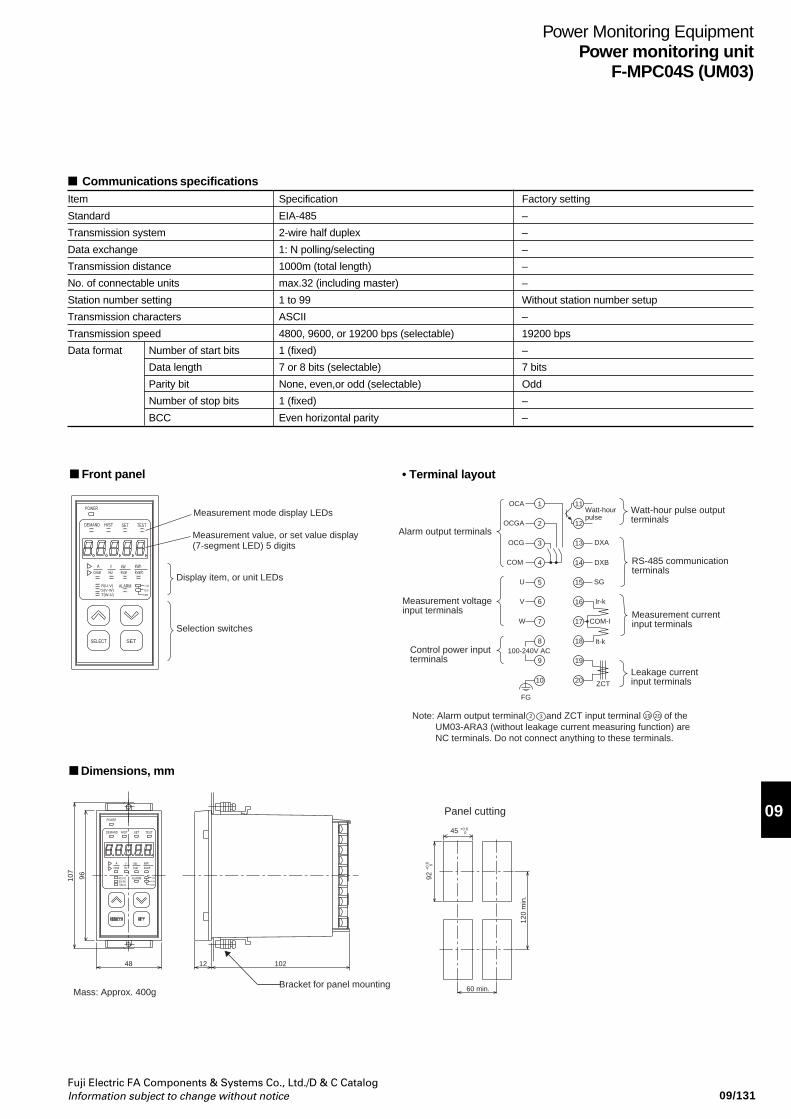
Fuji Electric FA Components & Systems Co., Ltd./D & C CatalogInformation subject to change without notice
Power Monitoring EquipmentPower monitoring unit
F-MPC04S (UM03)
09/131
09
Communications specificationsItem Specification Factory setting
Standard EIA-485 –
Transmission system 2-wire half duplex –
Data exchange 1: N polling/selecting –
Transmission distance 1000m (total length) –
No. of connectable units max.32 (including master) –
Station number setting 1 to 99 Without station number setup
Transmission characters ASCII –
Transmission speed 4800, 9600, or 19200 bps (selectable) 19200 bps
Data format Number of start bits 1 (fixed) –
Data length 7 or 8 bits (selectable) 7 bits
Parity bit None, even,or odd (selectable) Odd
Number of stop bits 1 (fixed) –
BCC Even horizontal parity –
Front panel • Terminal layout
Dimensions, mm
1
2
3
4COM
OCA
OCGA
OCG
5
6
100-240V AC
ZCT
7
U
V
W
FG
SG
DXA
DXB
8
9
10
13
14
17
18
19
20
19 20
Ir-k
It-k
COM-I
Watt-hourpulse
11
12Alarm output terminals
Measurement voltageinput terminals
Control power inputterminals
Watt-hour pulse outputterminals
RS-485 communicationterminals
Measurement currentinput terminals
Leakage currentinput terminals
Measurement mode display LEDs
Measurement value, or set value display(7-segment LED) 5 digits
Display item, or unit LEDs
Selection switches
2 3
15
16
S(V-W)R(U-V)
T(W-U)
TEST
X1000
X10
X100
SETHISTDEMAND
POWER
kvarhHzcosø kvarA V kWhkW
ALARM
SELECT SET
Note: Alarm output terminal and ZCT input terminal of the UM03-ARA3 (without leakage current measuring function) are NC terminals. Do not connect anything to these terminals.
S(V-W)R(U-V)
T(W-U)
TEST
X1000
X10
X100
SETHISTDEMAND
POWER
kvarhHzcosø kvarA V kWhkW
ALARM
1021248
96107
92+
0.8
0
45 +0.6 0
120
min
.
60 min.Bracket for panel mountingMass: Approx. 400g
Panel cutting
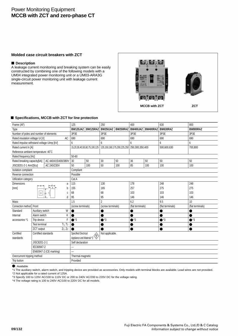
09/132Fuji Electric FA Components & Systems Co., Ltd./D & C Catalog
Information subject to change without notice
Power Monitoring EquipmentMCCB with ZCT and zero-phase CT
MCCB with ZCT ZCT
Molded case circuit breakers with ZCT
DescriptionA leakage current monitoring and breaking system can be easilyconstructed by combining one of the following models with aUM04 integrated power monitoring unit or a UM03-ARA3Gsingle-circuit power monitoring unit with leakage currentmeasurement.
Specifications, MCCB with ZCT for line protection
Frame (AF)TypeNumber of poles and number of elementsRated insulation voltage Ui [V]Rated impulse withstand voltage Uimp [kV]Rated current In [A]Reference ambient temperature: 40˚CRated frequency [Hz]Rated breaking capacity[kA]JISC8201-2-1 Ann2[lcu]Isolation complaintReverse connectionUtilization categoryDimensions[mm]
MassConnection methodStandardInternalaccessories *1
Certifiedstandards
Overcurrent tripping methodTrip button
: Available*1 The auxiliary switch, alarm switch, and tripping device are provided as accessories. Only models with terminal blocks are available. Lead wires are not provided.*2 Not applicable for a rated current of 125A.*3 Specify 100 to 120V AC/100 to 110V DC or 200 to 240V AC/200 to 220V DC for the voltage rating.*4 The voltage rating is 100 to 240V AC/100 to 220V DC for all models.
AC 440/415/400/380VAC 240/230V
Front Auxiliary switchAlarm switchTrip deviceTest terminalZCT outputCertified standards
JISC8201-2-1IEC60947-2EN60947-2 (CE marking)
AC
abcd
WKF
T1, T2
Z1, Z2
125BW125JAZ3P3E690615,20,30,40,50,60,75,100,125
50-603050CompliantPossibleCat.A11515568951.5(screw terminals)
*3
Specified Electrical Appliance and Material *2Self declaration——Thermal-magneticProvided
250BW250JAZ3P3E6906125,150,160,175,200,225,250
3050
13016568952(screw terminals)
*3
Not applicable.
400BW400JAZ3P3E6906250,300,350,400
3685
1782571031466.2(flat terminals)
*3
630BW630RAZ3P3E6906500,600,630
50100
2482751031469.5(flat terminals)
*3
800BW800RAZ3P3E6906700,800
50100
24827510314610(flat terminals)
*3
BW125RAZ
50100
BW250RAZ
50100
BW400RAZ
50100
ca d
b
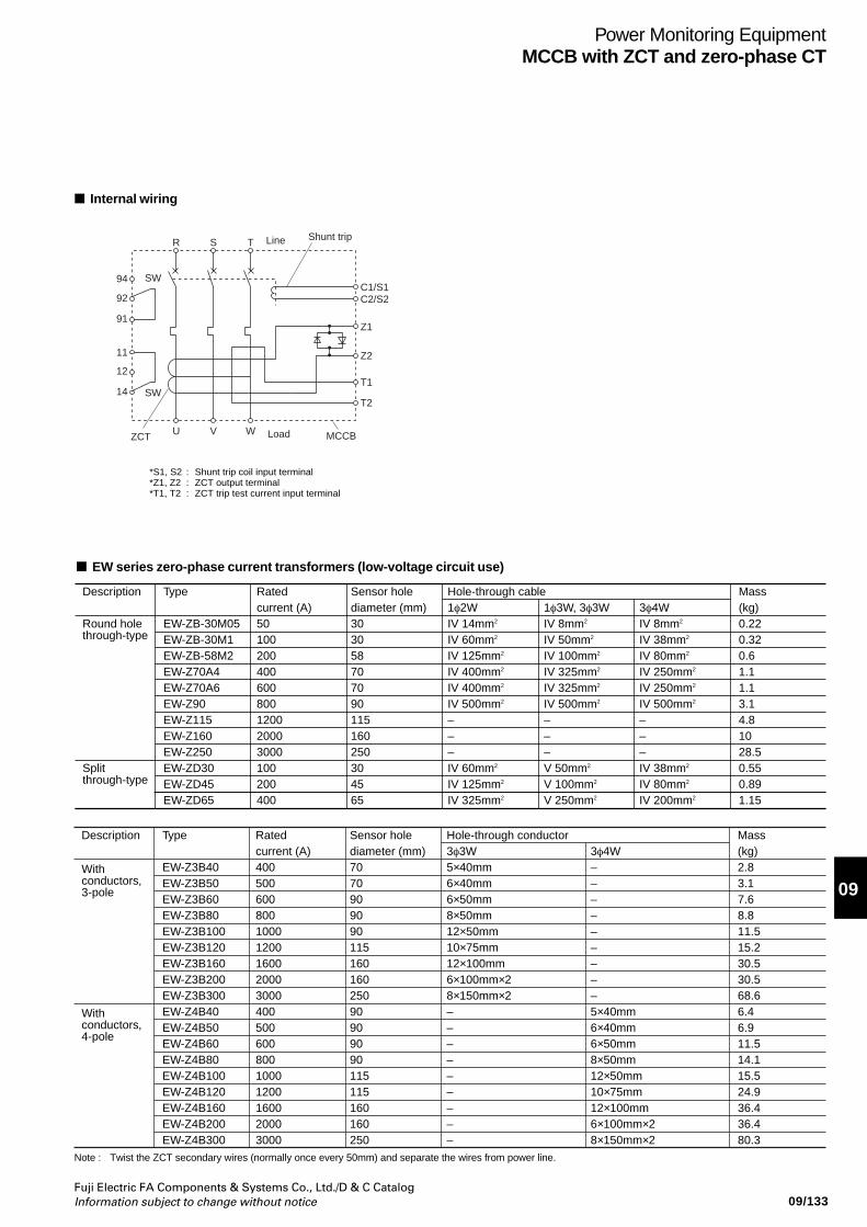
09/133Fuji Electric FA Components & Systems Co., Ltd./D & C CatalogInformation subject to change without notice
09
Power Monitoring EquipmentMCCB with ZCT and zero-phase CT
*S1, S2 : Shunt trip coil input terminal*Z1, Z2 : ZCT output terminal*T1, T2 : ZCT trip test current input terminal
Z1
C1/S1C2/S2
T1
T2
TSR
SW
SW
94
92
91
11
12
14
WVU
Z2
ZCT Load
Line Shunt trip
MCCB
Internal wiring
EW series zero-phase current transformers (low-voltage circuit use)
Note : Twist the ZCT secondary wires (normally once every 50mm) and separate the wires from power line.
Description
Round hole through-type
Split through-type
Type
EW-ZB-30M05EW-ZB-30M1EW-ZB-58M2EW-Z70A4EW-Z70A6EW-Z90EW-Z115EW-Z160EW-Z250EW-ZD30EW-ZD45EW-ZD65
Rated current (A)50100200400600800120020003000100200400
Sensor hole diameter (mm)303058707090115160250304565
Hole-through cable1φ2WIV 14mm2
IV 60mm2
IV 125mm2
IV 400mm2
IV 400mm2
IV 500mm2
–––IV 60mm2
IV 125mm2
IV 325mm2
1φ3W, 3φ3WIV 8mm2
IV 50mm2
IV 100mm2
IV 325mm2
IV 325mm2
IV 500mm2
–––V 50mm2
V 100mm2
V 250mm2
3φ4WIV 8mm2
IV 38mm2
IV 80mm2
IV 250mm2
IV 250mm2
IV 500mm2
–––IV 38mm2
IV 80mm2
IV 200mm2
Mass (kg)0.220.320.61.11.13.14.81028.50.550.891.15
Description
With conductors, 3-pole
With conductors, 4-pole
Type
EW-Z3B40EW-Z3B50EW-Z3B60EW-Z3B80EW-Z3B100EW-Z3B120EW-Z3B160EW-Z3B200EW-Z3B300EW-Z4B40EW-Z4B50EW-Z4B60EW-Z4B80EW-Z4B100EW-Z4B120EW-Z4B160EW-Z4B200EW-Z4B300
Rated current (A)4005006008001000120016002000300040050060080010001200160020003000
Sensor hole diameter (mm)707090909011516016025090909090115115160160250
Hole-through conductor3φ3W5×40mm6×40mm6×50mm8×50mm12×50mm10×75mm12×100mm6×100mm×28×150mm×2–––––––––
3φ4W–––––––––5×40mm6×40mm6×50mm8×50mm12×50mm10×75mm12×100mm6×100mm×28×150mm×2
Mass (kg)2.83.17.68.811.515.230.530.568.66.46.911.514.115.524.936.436.480.3
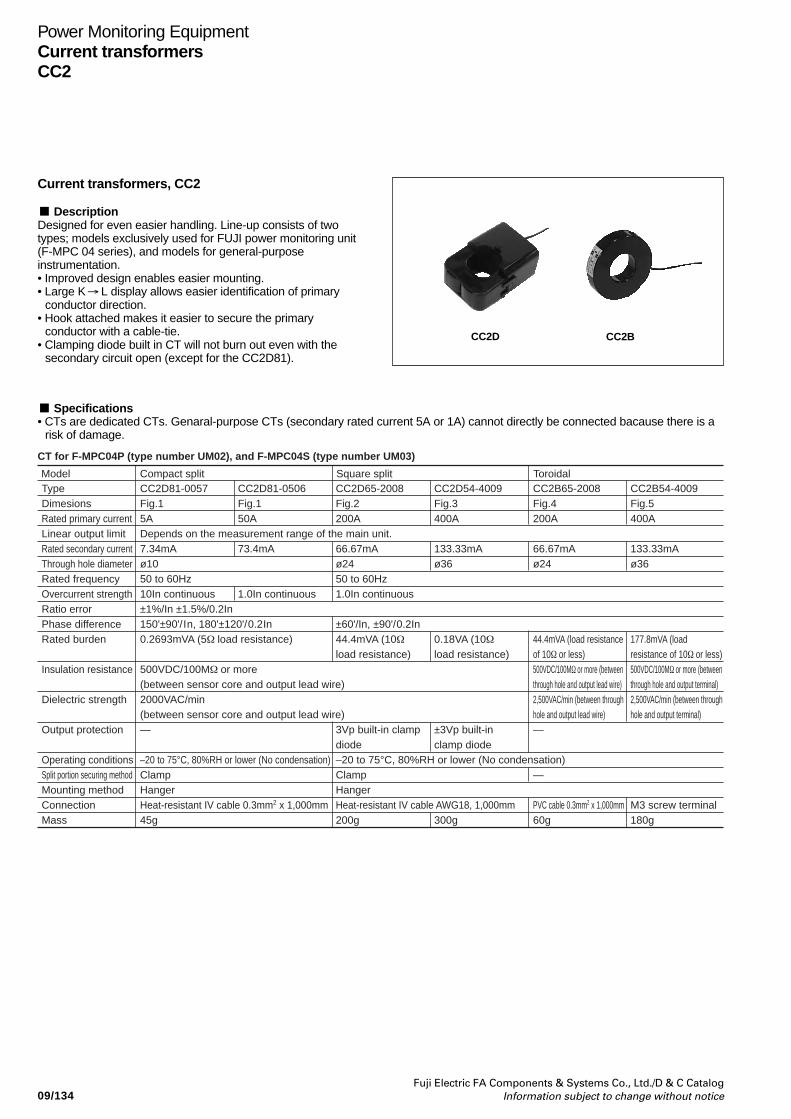
09/134Fuji Electric FA Components & Systems Co., Ltd./D & C Catalog
Information subject to change without notice
Power Monitoring EquipmentCurrent transformersCC2
Current transformers, CC2
DescriptionDesigned for even easier handling. Line-up consists of twotypes; models exclusively used for FUJI power monitoring unit(F-MPC 04 series), and models for general-purposeinstrumentation.• Improved design enables easier mounting.• Large K L display allows easier identification of primary
conductor direction.• Hook attached makes it easier to secure the primary
conductor with a cable-tie.• Clamping diode built in CT will not burn out even with the
secondary circuit open (except for the CC2D81).
Specifications• CTs are dedicated CTs. Genaral-purpose CTs (secondary rated current 5A or 1A) cannot directly be connected bacause there is a
risk of damage.
←
CC2BCC2D
Model ToroidalCompact split Square splitTypeDimesionsRated primary currentLinear output limitRated secondary currentThrough hole diameterRated frequencyOvercurrent strengthRatio error Phase differenceRated burden
Insulation resistance
Dielectric strength
Output protection
Operating conditionsSplit portion securing methodMounting methodConnectionMass
CC2B54-4009Fig.5400A
133.33mAø36
177.8mVA (load resistance of 10Ω or less)500VDC/100MΩ or more (between through hole and output terminal)2,500VAC/min (between through hole and output terminal)
M3 screw terminal180g
CC2B65-2008Fig.4200A
66.67mAø24
44.4mVA (load resistanceof 10Ω or less)500VDC/100MΩ or more (between through hole and output lead wire)2,500VAC/min (between through hole and output lead wire)—
—
PVC cable 0.3mm2 x 1,000mm60g
CC2D65-2008Fig.2200A
66.67mAø2450 to 60Hz1.0In continuous
±60'/In, ±90'/0.2In44.4mVA (10Ω
load resistance)
3Vp built-in clampdiode–20 to 75°C, 80%RH or lower (No condensation)ClampHangerHeat-resistant IV cable AWG18, 1,000mm 200g
CC2D54-4009Fig.3400A
133.33mAø36
0.18VA (10Ωload resistance)
±3Vp built-in clamp diode
300g
CC2D81-0506Fig.150A
73.4mA
1.0In continuous
CC2D81-0057Fig.15ADepends on the measurement range of the main unit.7.34mAø1050 to 60Hz10In continuous±1%/In ±1.5%/0.2In150'±90'/In, 180'±120'/0.2In0.2693mVA (5Ω load resistance)
500VDC/100MΩ or more (between sensor core and output lead wire)2000VAC/min(between sensor core and output lead wire)—
–20 to 75°C, 80%RH or lower (No condensation)ClampHangerHeat-resistant IV cable 0.3mm2 x 1,000mm 45g
CT for F-MPC04P (type number UM02), and F-MPC04S (type number UM03)
09/135Fuji Electric FA Components & Systems Co., Ltd./D & C CatalogInformation subject to change without notice
09
Power Monitoring EquipmentCurrent transformers
CC2
Specifications
Model Toroidal splitSquare splitTypeDimesionsRated primary currentLinear output limit
Rated frequencyOvercurrent strengthRatio errorPhase differenceRated burdenInsulation resistance
Dielectric strength
Output protection
Mounting methodConnectionMass
CC2C76-8001Fig.6800A
ø60
±1%/In ±1.5%/0.2In ±3%/0.05In±80'/In, ±100'/0.2In
500VDC/100MΩ or more (between through hole and output)2500VAC/min (between through hole and output)
Vinyl cabtire cable 0.75mm2 x 1,000mm 2-core500gUM04X-1
CC2D74-4001
400A
±80'/ In
CC2D74-2001
200A
60±60'/ In
CC2D74-1001Fig.3100ADepends on the measurement range of the main unit.
1.0In continuous±1%/In ±1.5%/0.2In90±90'/ In
Ω
Ω or more(between sensor core and output lead wire)2000VAC/min(between sensor core and output lead wire)
– °C, 80%RH or lower (No condensation)ClampHangerHeat-resistant IV cable AWG18, 1,000mm300gUM04X-1
CT for F-MPC04 (type number UM04)
CC2C76-12X1
1,200A
•• For CTs without build-in output protection diode, be sure to draw a primary current after connecting a rated load. Drawing a primary current without connecting
• CT-BOX to be used together with general-purpose CT (10 to 7500A/5A) is the UM04X-5.
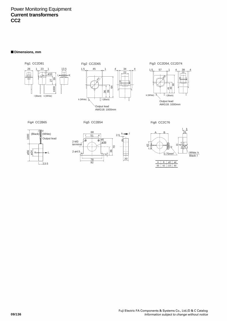
09/136Fuji Electric FA Components & Systems Co., Ltd./D & C Catalog
Information subject to change without notice
Power Monitoring EquipmentCurrent transformersCC2
Dimensions, mm
1 126 23 13.5
2739
1000
ø10 L K
l (Black) k (White)
ø36
1.5 57 1 4 38 422
45 4980
K L
l (Black)
l (Black)
k (White)
k (White)
451.5 1 4 34 422
36 3964
K Lø24
Output leadAWG18: 1000mm
Output leadAWG18: 1000mm
Fig1 CC2D81 Fig3 CC2D54, CC2D74Fig2 CC2D65
øD
115
B
62
A
65
ød
60
Fig5 CC2B54Fig4 CC2B65
l k
Fig6 CC2C76
White: kBlack: l
A B
0.75mm2
25
42 D d
7036
8
7
207892
2.5k l
5168
k
ø362-M3terminal
2-ø4.5
ø56
ø24
1000
13.5
(Black) (White)
Output lead
k
K L
l
l
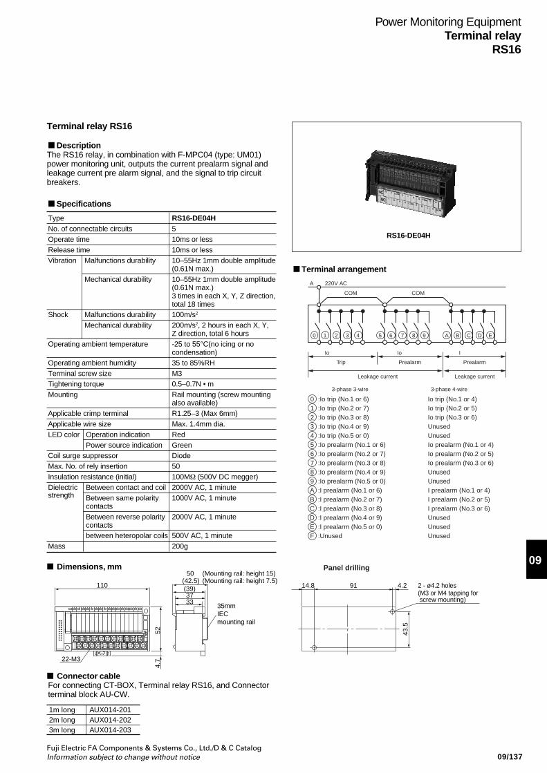
09/137Fuji Electric FA Components & Systems Co., Ltd./D & C CatalogInformation subject to change without notice
09
Power Monitoring EquipmentTerminal relay
RS16
RS16-DE04H
Terminal relay RS16
DescriptionThe RS16 relay, in combination with F-MPC04 (type: UM01)power monitoring unit, outputs the current prealarm signal andleakage current pre alarm signal, and the signal to trip circuitbreakers.
C D EBA
A
7 8 9652 3 410
PrealarmPrealarmTrip
3-phase 3-wire 3-phase 4-wire
Leakage current Leakage current
Io Io I
0123456789ABCDEF
:Io trip (No.1 or 6):Io trip (No.2 or 7):Io trip (No.3 or 8):Io trip (No.4 or 9):Io trip (No.5 or 0):Io prealarm (No.1 or 6):Io prealarm (No.2 or 7):Io prealarm (No.3 or 8):Io prealarm (No.4 or 9):Io prealarm (No.5 or 0):I prealarm (No.1 or 6):I prealarm (No.2 or 7):I prealarm (No.3 or 8):I prealarm (No.4 or 9):I prealarm (No.5 or 0):Unused
Io trip (No.1 or 4)Io trip (No.2 or 5)Io trip (No.3 or 6)UnusedUnusedIo prealarm (No.1 or 4)Io prealarm (No.2 or 5)Io prealarm (No.3 or 6)UnusedUnusedI prealarm (No.1 or 4)I prealarm (No.2 or 5)I prealarm (No.3 or 6)UnusedUnusedUnused
220V AC
COM COM
Terminal arrangement
43.5
14.8 4.2 2 - ø4.2 holes(M3 or M4 tapping for screw mounting)
91
50 (Mounting rail: height 15)
(39)3733
(42.5) (Mounting rail: height 7.5)110
524.
722-M3
35mmIECmounting rail
Panel drilling
Connector cableFor connecting CT-BOX, Terminal relay RS16, and Connectorterminal block AU-CW.
Dimensions, mm
1m long2m long3m long
AUX014-201AUX014-202AUX014-203
Type RS16-DE04HNo. of connectable circuits 5Operate time 10ms or lessRelease time 10ms or lessVibration Malfunctions durability 10–55Hz 1mm double amplitude
(0.61N max.)Mechanical durability 10–55Hz 1mm double amplitude
(0.61N max.)3 times in each X, Y, Z direction,total 18 times
Shock Malfunctions durability 100m/s2
Mechanical durability 200m/s2, 2 hours in each X, Y,Z direction, total 6 hours
Operating ambient temperature -25 to 55°C(no icing or nocondensation)
Operating ambient humidity 35 to 85%RHTerminal screw size M3Tightening torque 0.5–0.7N • mMounting Rail mounting (screw mounting
also available)Applicable crimp terminal R1.25–3 (Max 6mm)Applicable wire size Max. 1.4mm dia.LED color Operation indication Red
Power source indication GreenCoil surge suppressor DiodeMax. No. of rely insertion 50Insulation resistance (initial) 100MΩ (500V DC megger)Dielectric Between contact and coil 2000V AC, 1 minutestrength Between same polarity 1000V AC, 1 minute
contactsBetween reverse polarity 2000V AC, 1 minutecontactsbetween heteropolar coils 500V AC, 1 minute
Mass 200g
Specifications
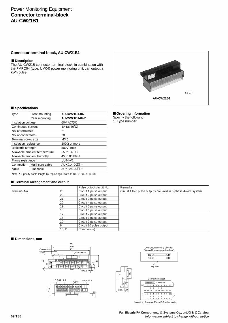
09/138Fuji Electric FA Components & Systems Co., Ltd./D & C Catalog
Information subject to change without notice
Power Monitoring EquipmentConnector terminal-blockAU-CW21B1
AU-CW21B1
SB-277
Connector terminal-block, AU-CW21B1
DescriptionThe AU-CW21B connector terminal-block, in combination withthe FMPC04 (type: UM04) power monitoring unit, can output akWh pulse.
Type
Insulation voltage Continuous current No. of terminalsNo. of connectorsTerminal screw size Insulation resistanceDielectric strengthAllowable ambient temperatureAllowable ambient humidityFlame resistanceConnection cable
Note: * Specify cable length by replacing with 1: 1m, 2: 2m, or 3: 3m.
Front mountingRear mounting
Multi-core cableFlat cable
AU-CW21B1-04AU-CW21B1-04R60V AC/DC1A (at 40˚C)2120M3.5100Ω or more500V 1min–5 to +40˚C45 to 85%RHUL94-V1AUX014-20 *AUX024-20 *
Specifications
Terminal arrangement and output
Terminal No. 232221201918171610915, 2
Pulse output circuit No.Circuit 1 pulse outputCircuit 2 pulse outputCircuit 3 pulse outputCircuit 4 pulse outputCircuit 5 pulse outputCircuit 6 pulse outputCircuit 7 pulse outputCircuit 8 pulse outputCircuit 9 pulse outputCircuit 10 pulse outputCommon (–)
RemarksCircuit 1 to 6 pulse outputs are valid in 3-phase 4-wire system.
1010
8
8.89 16.5Cover
7.112 8.89
44.7
151140131
ConnectorConnectionsheet
4.5 44
6M3.5
9.4
15.6
653
33
Connection sheet
35
B1A1
Connector mounting direction(Viewed from engaged surface)
Key way
8 620.5 11.2
33.5 13.5
Connector No. /Terminal No.1 2 3 4 5 6 7 8 9 10
1 2 3 4 5 6 7 8 9 10
1 2 3 4 5 6 7 8 9 10
14 15 16 17 18 19 20 21 22 23
B
A
Mounting: Screw or 35mm IEC rail mounting
Dimensions, mm
Ordering informationSpecify the following:1. Type number
Catalog DisclaimerThe information contained in this catalog does not constitute an express or implied warranty of quality, any warranty of merchantability of fitness for a particular purpose is hereby disclaimed.
Since the user's product information, specific use application, and conditions of use are all outside of Fuji Electric FA Components & Systems'control, it shall be the responsibility of the user to determine the suitability of any of the products mentioned for the user's application.
One Year Limited WarrantyThe products identified in this catalog shall be sold pursuant to the terms and conditions identified in the"Conditions of Sale" issued by Fuji Electric FA with each order confirmation.
Except to the extent otherwise provided for in the Conditions of Sale issued by Fuji Electric FA, Fuji Electric FA warrants that the Fuji Electric FA products identified in this catalog shall be free from significant defects in materials and workmanship provided the product has not been: 1) repaired or altered by others than Fuji Electric FA; 2) subjected to negligence, accident, misuse, or damage by circumstances beyond Fuji Electric FA's control; 3) improperly operated, maintained or stored; or 4) used in other than normal use or service. This warranty shall apply only to defects appearing within one (1) year from the date of shipment by Fuji Electric FA, and in such case, only if such defects are reported to Fuji Electric FA within thirty (30) days of discovery by purchaser. Such notice should be submitted in writing to Fuji Electric FA at 5-7, Nihonbashi Odemma-cho, Chuo-ku, Tokyo, Japan. The sole and exclusive remedy with respected to the above warranty whether such claim is based on warranty, contract, negligence, strict liability or any other theory, is limited to the repair or replacement of such product or, at Fuji Electric FA's option reimbursement by Fuji Electric FA of the purchase price paid to Fuji Electric FA for the particular product. Fuji Electric FA does not make any other representations or warranties, whether oral or in writing, expressed or implied, including but not limited to any warranty regarding merchantability or fitness for a particular purpose. Except as provided in the Conditions of Sale, no agent or representative of Fuji Electric FA is authorized to modify the terms of this warranty in writing or orally. In no event shall Fuji Electric FA be liable for special, indirect or consequential damages, including but not limited to, loss of use of the product, other equipment, plant and power system which is installed with the product, loss of profits or revenues, cost of capital, or claims against the purchaser or user of the product by its customers resulting from the use of information, recommendations and descriptions contained herein. The purchaser agrees to pass on to its customers and users, in writing at the time inquiries and orders are received by buyer, Fuji Electric FA's warranty as set forth above.
Caution "Safety precautions"• Operate (keep) in the environment specified in the operating instructions and manual. High temperature, high
humidity, condensation, dust, corrosive gases, oil, organic solvents, excessive vibration or shock might cause electric shock, fire, erratic operation or failure.
• Follow the regulations of industrial wastes when the product is to be discarded.• The products covered in this catalogs have not been designed or manufactured for use in equipment or systems
which, in the event of failure, can lead to loss of human life.• If you intend to use the products covered in this catalog for special applications, such as for nuclear energy control,
aerospace, medical, or transportation, please consult our Fuji Electric FA agent.• Be sure to provide protective measures when using the product covered in these catalogs in equipment which, in the
event of failure, may lead to loss of human life or other grave results.• Follow the directions of the operating instructions when mounting the product.
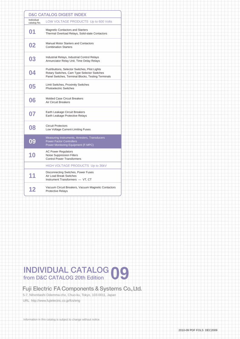
Information in this catalog is subject to change without notice.
5-7, Nihonbashi Odemma-cho, Chuo-ku, Tokyo, 103-0011, Japan URL http://www.fujielectric.co.jp/fcs/eng
IND
IVID
UA
L CA
TA
LOG
from
D&
C C
AT
ALO
G 20th E
ditio
n
09
LOW VOLTAGE PRODUCTS Up to 600 VoltsIndividualcatalog No.
01 Magnetic Contactors and StartersThermal Overload Relays, Solid-state Contactors
02
Industrial Relays, Industrial Control RelaysAnnunciator Relay Unit, Time Delay Relays
Manual Motor Starters and Contactors Combination Starters
Pushbuttons, Selector Switches, Pilot LightsRotary Switches, Cam Type Selector SwitchesPanel Switches, Terminal Blocks, Testing Terminals
Molded Case Circuit BreakersAir Circuit Breakers
Earth Leakage Circuit BreakersEarth Leakage Protective Relays
Measuring Instruments, Arresters, TransducersPower Factor ControllersPower Monitoring Equipment (F-MPC)
Circuit ProtectorsLow Voltage Current-Limiting Fuses
03
04
05
06
07
08
09
10
HIGH VOLTAGE PRODUCTS Up to 36kV
11Disconnecting Switches, Power FusesAir Load Break SwitchesInstrument Transformers — VT, CT
D&C CATALOG DIGEST INDEX
AC Power RegulatorsNoise Suppression FiltersControl Power Transformers
12 Vacuum Circuit Breakers, Vacuum Magnetic ContactorsProtective Relays
Limit Switches, Proximity SwitchesPhotoelectric Switches
01 02 03 04 05 06 07 08 09 10 11 12
LOWVOLTAGE
EQUIPMENTUp to 600 Volts
INDIVIDUAL CATALOGfrom D&C CATALOG 20th Edition 09INDIVIDUAL CATALOG
from D&C CATALOG 20th Edition 09
MEASURING INSTRUMENTS
POWER MONITORING EQUIPMENT (F-MPC)
TRANSDUCERS
POWER FACTOR CONTROLLERS
ARRESTERS
Panel instruments Transducers
Arresters
Instrument transformers
Automatic power factorregulators
Switchboard instruments
Power monitoringequipment F-MPC
2010-09 PDF FOLS DEC2009