0s/vs2 mvs system programming library: sys1.l0grec error
TRANSCRIPT

GC28-0677-5
File No. S370-37
4'low^
0S/VS2 MVS System ProgrammingLibrary: SYS1.L0GREC Error
Systems Recording

5
Sixth Edition (December, 1981)
This is a major revision of, and obsoletes, GC28-0677-4 and Technical NewslettersGN25-0344 and GN28-4745. Consult theSummary of Amendments following theContentsDirectory for a list of the new or changed information.
This edition applies to Release I and all subsequent releases of MVS/SystemProduct(5740-XYN,-XYS) untilotherwise indicated in neweditions or Technical Newsletters.
Changes arecontinually made to the information herein; before using this publication, consultthe latest IBMSystem/370 Bibliography, GC20-0001, and the technicalnewsletters thatamend thebibliography, to leam which editions and technical newsletters are applicable andcurrent.
It is possible that this material may contain reference to, or information about, IBM products(machines and programs), programming or services that arenot announced in your country.Such references or information must not be construed to mean that IBM intends to announcesuch IBM products, programming or services in yourcountry.
Publications are notstocked at the address given below; requests forcopies of IBMpublications should be made to your IBM representative or to the IBM branch office servingyour locality.
A form for reader's comments is provided at the back of this publication. If the form hasbeen removed, comments may beaddressed to IBM Corporation, Publications Development,Department D58, Building 706-2, PO Box 390, Poughkeepsie, New York 12602. IBM may ruse or distribute anyof the information you supply in any way it believes appropriate withoutincurring any obligation whatever. You may, of course, continue to use the information yousupply.
© Copyright International Business Machines Corporation 1974, 1981

Preface
This publication describes how different errors and system conditions arerecorded on the SYSl.LOGREC data set and how SYSl.LOGREC isinitialized and maintained. It discusses why and how the different types ofrecords are built and recorded on SYS1.LOGREC, and how to use theservice aid programs that maintain the SYSl.LOGREC data set.
^ Contents
f. This publication contains three parts:
:• • Chapter 1: Introduction describes the overall error recording functionas it applies to the SYS1.LOGREC data set.
• Chapter 2: Initializing and Reallocating the SYSl.LOGREC Data Setshows how to use the IFCDIPOO service aid to initialize and maintainthe SYS1.LOGRBC data set.
• Error Recording on SYSl.LOGREC explains the error and systemcondition recording functions, the conditions documented by each typeof record, and the format of each record on SYSl.LOGREC.
Prerequisite Publication
• OS/VS Utilities, describes how to use utility programs to print certain' types of service aid output and to allocate data sets with die
lEHPROGM utUity.
Associated Publications
• OS/VS2 MVS JCL, GC28-0692, describes how to use job controlstatements to override default parameters, use cataloged procedures,allocate space for data sets, code job control statements, and how touse JES2 control statements with other JCL statements.
OS/VS2 MVS SYSl.LOGREC Error Recording Logic, SY28-0678,describes the internal logic of IFCDIPOO, and the system recordingroutines: asynchronous recording facility, DDR/MIH recorder, MCHemergency recorder, OBR/MDR recorder, SVC 76, and SVC 91.
• Environmental Recording Editing and Printing (EREP) Program,GC28-0772, describes how to use DFCEREPl service aid.
• Environmental Recording Editing and Printing (EREP) Program Logic,SY28-0773, describes the internal logic of IFCEREPl andAMDPRDMP service aid programs.
j • OS/VS Mass Storage System (MSS) System Data Analyzer,7 GC35-0027, describes the ISDASDAO support for the IBM 3850
Mass Storage System.
• EREP Messages, GC38-1045, describes the messages issued byIFCEREPl service aid program.
• OS/VS2 MVS I/O Supervisor Logic, SY26-3823, describes thedevice-dependent error recovery procedures.
• OS/VS2 Service Aids Reference Summary, GX23-0002, provides asummary of reference information for OS/VS2.
• OS/VS2 SPL: Debugging Handbook, Volume 3, GC28-0709, describesdetailed format of the SDWA.
Preface ili
i
0S/VS2 MVS System Generation Reference^ GC26-3792, providesinformation for system programmers who are to plan for and install anOS/VS2 System Control Program and a JESS Job Entry Subsystem.
iv OS/VS2 MVS SystemPrognunming Ubraiy: SYS1.LOGREC Error Reconfiiig

Contents
Chapter 1. IntroductionInitializing the SYSl.LOGREC DataSet 1-1Recording Records on SYSl.LOGREC 1-2Retrieving Information on SYSl.LOGREC 1-3
Chapter 2. Initializing and Reallocating the SVSI.LOGREC Data Set (IFCDIPOO) 2-1SYSl.LOGREC Header Record 2-1Time Stamp Record 2-3Frame Record 2-5Reinitializing SYSl.LOGREC 2-6
Example 1: Reinitializing the SYSl.LOGREC Data Set 2-6Changing Space Allocation for SYSl.LOGREC 2-6
Example 2: Changing Space Allocation for SYSl.LOGREC 2-6Example 3: Replacing Frames on SYSl.LOGREC 2-7Example 4: Replacing Frames on SYSl.LOGREC on a Multiprocessor 2-8
Chapter 3. Error Recording on SYS1.LOGREC 3-1Types of Records on SYSl.LOGREC 3-1
Record Header 3-4Recording Channel Inboard (CCH) Records 3-6Recording Dynamic Device Reconfiguration (DDR) Records 3-11Recording Machine Check (MCH) Records 3-12
Soft Failures 3-13Hard Failures 3-13
Recording Miscellaneous Data (MDR) Records 3-18Buffer Overflow 3-18Demounts 3-18Device Failures 3-19
Recording Missing Interruption Handler (MIH) Records 3-21Recording Output (OBR) Records 3-23
Channel Failures 3-23Device Failures 3-24Paging I/O Errors 3-25Statistical Recording 3-25IFCEREPl Recording 3-26Teleprocessing Device Recording 3-273400 Demount Recording 3-28
RecordingSoftware Records 3-31Recording System Initialization (IPL) Records 3-35
Specifying RDE DuringSystem Generation 3-36IPL Recording with RDE 3-37
Reco^ng System Termination (EOD) Records 3-39
Index I-l
Contents v

Figures
1-1. SYSl.LOGREC Error Recording Overview 1-12-1. SYSl.LOGREC Header Record Format 2-22-2. Time Stamp Record Format 2-42-3. Frame Record Format 2-53-1. Writing Records Onto SYS1.L0GREC 3-23-2. Incident/Record Table 3-33-3. CCH Record Format 3-73-4. DDR Record Format 3-113-5. MCH Record Format 3-143-6. MDR Record Format 3-193-7. MIH Record Format 3-223-8. Long OBR RecordFormat 3-283-9. Short OBR Record Format 3-303-10. Software Record Format 3-323-11. IPL Record Format 3-353-12. IPL Reason Codes 3-383-13. Subsystem ID Codes 3-383-14. EOD Record Format 3-39
Figures vil

Summary of Amendments
Summary of Amendmentsfor GC28-0677-5
as Updated December 30, 1981for MVS/System Product Release 3This revision incorporates information from Technical Newsletters GN25-0344, GN28-4775,and Supplements GD23-0201, GD25-0601-0, GD25-06b5-0, and GD25-0608-0, and includesminor technical and editorial changes.
Summary of Amendmentsfor GC28-0677-4
OS/VS2 MVS Release 3.7
Retrieving and Writing Recordsfrom the SYS1.LOGRECData Set (IFCEREPO)
The service aid EREP has been deleted from this publication. For information on retrievingand writingrecords from the SYSl.LOGREC data set, reference OS/VS EnvironmentalRecording Editing and Printing (EREP) Program.
ISDASDAO for the IBM 3850 Mass Storage System
Mass Storage System Data Analyzer (SDA) has been deleted from this publication. Forinformation on ISDASDAO, reference OS/VS Mass Storage System (MSS) System DataAnalyzer.
Summary of Amendmentsfor GC28-0677-3
OS/VS2 Release 3.7
IBM 3344 Direct Access Storage Device
SYSl.LOGREC supports GBR and MDR recording of device failures and statistical data forthe IBM 3344 Direct Access Storage Device only in emulation mode for the IBM 3340.
IBM 3350 Direct Access Storage
SYSl.LOGREC supports OBR and MDR recording of device failures and statistical data forthe IBM 3350 Direct Access Storage.
Error Record Edit and Print (EREP)
EREP improves summary outputs for storage products. (IBM Direct Access Storage Devicesand IBM 3420 Tape Drives.)
Summary of Amendments ix

Chapter 1. Introduction
The purpose of error recording on the SYS1.LOGREC data set is toprovide a record of all hardware failures, selected software errors, andsystem conditions. Information about each incident is written ontoSYS1.LOGREC by the system recording routines and can be retrieved byusing the IFCEREPl service aid. The IFCEREPl output can be used fordiagnostic and/or measurement purposes to maintain the devices and
' support the system control program of a computer system.
Error recording on SYSl.LOGREC, as shown in Figure 1-1, involves:
• • Initialization of SYSl.LOGREC by the IFCDIPOO service aid.
• Recording records of different incidents on SYSl.LOGREC.
• Retrieval of the information on SYS1.LOGREC by using theIFCEREPl service aid.
Initializing the SYS1.LOGREC Data SetThe IFCDIPOO service aid initializes the SYSl.LOGREC data set on thesystem residence volume during system generation. IFCDIPOO creates aheader record and a time stamp record for the SYS1.LOGREC data setand allocates space for the data set which must reside on the systemresidence volume. IFCDIPOO can also be used to reallocate and reinitializeSYS1.L0GREC. IFCDIPOO is described in "Chapter 2: Initializing, andReallocating the SYS1.L0GREC Data Set (IFCDIPOO)."
After the first IPL or an engineering change, IFCDIPOO is used to place"frames" - editing instructions for MCH and CCH records - onSYSl.LOGREC. This process is only applicable on systems which have aService Record File (7443-1 device type).
Figure 1-1. SVS1.LOGREC Error Recording Overview
Chapter 1. Introduction 1-1

Recording Records on SYS1.LOGRECTwelve types of records, containing device- or incident-dependentinformation, can be recorded on SYSl.LOGREC:
CCF records for editing the channel-dependent logout of systems thathave a Service Record File.
CCH records for channel failures.
DDR records for information describing operator and system swapsbetween direct access and magnetic tape devices and for operatorswaps on unit record devices.
EOD records for information related to end-of-day conditionswhenever the RDE option has been included in the system.
IPL records for information related to system initializations wheneverthe RDE option has been includedin the system, and for power-linedisturbances that cause system termination.
MCF records for editing the machine-dependent logout of systemsthat have a Service Record File.
MCH records for CPU, storage, storage key, timer failures, and forpower-line disturbances that do not cause system termination.
MDR records for buffer overflow and device failures on buffered logdevices, for demounts on direct access devices with buffered logs, fordemounts by the lEHDASDR utility program between direct accessdevices having buffered logs and removable disk packs, for devicefailures on teleprocessing devices connected to an IBM 3704 or 3705device, and for statistical recording by IFCEREPl service program ondirect access devices with buffered logs.
MIH records for information describing pending (missing) channel anddevice ends of all devices except 1275 PCU, 1419 PCU, and allteleprocessing devices except local 3704/3705 and 3791.
OBR records for counter overflow statistics and device failures ondevices supported by the teleprocessing access methods, forend-of-day requests, for paging I/O errors, for permanent channel andI/O device failures, for statistic counter overflow, for temporary orintermittent I/O device failures, for demounts on the IBM 3400 seriesof magnetic tape devices, for devices that have their own diagnosticbuffers, and for statistical recording by IFCEREPl service aidprogram on direct access devices with buffered logs.
SOFTWARE records for routines affected by the issuing of theCALLRTM or ABEND macros for software detected software errorssuch as programs issuing SVC 13 (ABEND), for hardware detectedsoftware errors such as program checks, for operator detected errorssuch as pressing the restart key, and for hardware detected hardwareerrors such as software recovery attempts for hard machine failures.
TIME STAMP record for measuring approximate time intervalbetween termination and re-initialization of the operating system.
1-2 OS/VS2 MVS System Programming Ubraiy: SVS1.LOGREC Error Recording

Each record on SYSl.LOGREC contains complete and specific informationfor the device, and type of failure or system condition that caused it to bewritten. "Chapter 3: Error Recording on SYSl.LOGREC" describesSYSl.LOGREC recording and the record formats on SYSl.LOGREC.
Retrieving Information on SYSl.LOGRECThe Environmental Recording Editing and Printing (ERE?) service aidprogram enables you to examine the data recorded on SYSl.LOGRECand/or Accumulation data sets in the forms of system and summaryreports, edited records and record summaries.
ERE? can perform the following functions:
Create an Accumulation data set from the SYSl.LOGREC data setand clear SYS1.LOGREC.
Copy an Input Accumulation data set to an Output Accumulation dataset.
Merge data from an Accumulation data set and SYS1.L0GREC.
Print a detailed description of the hardware and software errorrecords.
Summarize and print statistics for device failures.
See Environmental Recording Editing and Printing (EREP) Program for theinformation on using DFCEREPl service aid.
Choiiter 1. IntroductioD 1-3

Chapter 2. Tnitinlijing and Reallocating the SYS1.LOGRECData Set (IFCDIPOO)
The disk initialization program (IFCDIPOO), controlled by job controllanguage statements, runs as a problem program under OS/VS2, and hasfive applications:.
• During system generation to initialize the SYSl.LOGREC data set.^ Initializing SYSl.LOGREC creates a header record and a time stamp
record on the data set and allocates space for the data set on thesystem residence volume. See 0S/VS2 System Programming Library:
® System Generation Reference for a discussion of this application.
• As a service aid to reinitialize the SYSl.LOGREC data set. TheSYSl.LOGREC header record can be destroyed if an uncorrectablechannel error occurs while IFCEREPl or a system recording routine isrewriting the header record onto the SYS1.LOGREC data set. UseIFCDIPOO to reinitialize the data set.
• As a service aid to modify the space allocation for theSYSl.LOGREC data set. If you need to change the size of theSYS1.LOGREC data set, created by the system generation process,use IFCDIPOO to increase or decrease the space allocation forSYS1.LOGREC.
As a service aid, after the first IPL of OS/VS2 on a processor havinga Service Record File (SRF), to read MCH and CCH edit formatinformation, format it into MCF and CCF "frame" records, and writethe records on SYS1.L0GREC.
• As a service aid, to replace the MCF and CCF records onSYS1.LOGREC after an engineering change that affected the editformat information on the SRF, or after loss of MCF or CCF framesfrom SYS1.LOGREC.
The system generation process selects the IFCDIPOO module and puts it inthe system control program's link library (SYSl.LINKLIB). IFCDIPOO is astandard service aid program of the OS/VS2 system control program.
SYS1.LOGREC Header Record
The IFCDIPOO service aid creates a header record on the SYSl.LOGRECdata set. The SYSl.LOGREC header record (Figure 2-1) provides:
• Information for the system recording routines to determine where towrite new record entries on SYSl.LOGREC.
• Information for the IFCEREPl service aid to find existing recordentries on SYSl.LOGREC.
• Information for the system recording routines to issue a warningmessage when the SYSl.LOGREC data set is 90% full.
Chapter 2. Initializing and ReaOocating the SYSl.LOGREC Data Set(IFCDIPOO) 2-1

SYSl.LOGRECHeaderRecordFormat
OffsetSize(Bytes)Field
DecHexAlignment(Bits)NameDescription0(0)2CLASRCHeaderrecordidentifier.Eachbitinthisfieldissetto1unless
criticaldatahasbeendestroyed.
2(2)4LOWLIMITAddressoflowextent.Trackaddress(inCCHHformat)offirstextentofSYSl.LOGREC.
6(6)4UPLIMITAddressofhighextent.Trackaddress(inCCHHformat)oflastextentofSYSl.LOGREC.
10(A)1MSGCNTCountofthenumberoftimesIFB040Ihasbeenissued.
11(B)7RESTARTAddressofrecordentryarea.Startingtrackaddress(inBBCCHHRformat)forrecordingareaonSYSl.LOGREC.
18(12)2BYTSREMRemainingbytesontrack.Numberofbytesremainingontrackuponwhichlastrecordentrywaswritten.
20(14)2TRKCAPTotalbytesontrack.NumberofbyteswhichcanbewrittenonatrackofvolumecontainingSYSl.LOGREC.
22(16)7LASTTRAddressoflastrecordwritten.TrackaddressBBCCHHRformat)oflastrecordwrittenonSYS1.LOGREC.
29ID)2TRKSPERHighestaddressabletrackforeachcylinderonvolumecontainingSYSl.LOGREC.
31IF)2EWMCNTWarningcount.NumberofbytesremainingonearlywarningmessagetrackofSYSl.LOGRECwhen90%fullpointofdatasetisreached.Whenthisisdetectedbyarecordingroutine,itissuesamessageandturnsonearlywarningmessageswitchatdisplacement38.
33(21)1DEVCODEDevicecode.CodeindicatingdevicetypeofsystemresidencevolumeonwhichSYSl.LOGRECresides:
CodeDevice
012311(notsupportedbyVS)022301
032303
042302
062305MODI
072305MODU
082314
093330and3333MODIor3350operatingin3330-1compatibilitymode.
OA3340and3344
OB3350nativemodeOC3375
OD3330and3333MODnor3350operatingin3330-ncompatibilitymode.
OE3380
OFFixedBlockDevice
Figure2-1(PartIof2).SYSl.LOGRECHeaderRecordFormat
2-2OS/VS2MVSSystemProgramniiiiglibrary:SYS1.LOGRECErrorRecoidiiig

Offset Size (Bytes) Field
Dec Hex Alignment (Bits) Name Description
34 (22) 4 EWMTRK Earlywarning message track. Trackaddress (in CCHH format)on which 90% full point for data set exists.
38 (26) 1
I
EWMSW Switch byte:90% full point message has been issued. This switch is turnedon by recording routine detecting 90% full point and is turnedoff by IFCEREPl when clearingSYSI.LOGREC tohexadecimal zeros.
..1 FRAMES Frames exist on SYSI.LOGREC.
.x.x xxxx Reserved.
39 (27) 1 SFTYBYTS Check byte. Each bit in this field is set to 1 and is used tocheck validity of header record identifier.
Figure 2-1 (Part 2 of 2). SYSI.LOGRECHeader RecordFormat
Time Stamp RecordThe IFCDIPOO service aid creates a time stamp record on theSYS1.LOGREC data set in the first record space following theSYSI.LOGREC header record. The time stamp record (Figure 2-1)provides current date and time information for the IPL record. This allowsthe user to measure the approximate time interval, recorded in the IPLrecords, between the termination and reinitialization of the operatingsystem.
When RDE is specified at SYSGEN time, the master scheduler invokes themissing interruption handler (MIH) at a time interval specified by the user.The missing interruption handler (module IGFTMCHK) issues SVC 76.SVC 76 then obtains the current date and time and and writes thisinformation on the time stamp record, overlaying the previous date andtime.
If MIH is invoked by the master scheduler during the initialization of theoperating system, MIH (module IGFTMCHK) issues SVC 76 to format anIPL record. SVC 76 obtains the date and time from the time stamp recordand adds it to the IPL record.
Note: If the IFCDIPOO service aid is used to reinitialize theSYS1.LOGREC data set, the information in the time stamp record isoverlaid with hexadecimal zeros until SVC 76 is used to write the date andtime.
Chapter2. intriatiTtng and Reallocating the SYSI.LOGREC Data Set (IFCDIPOO) 2-3
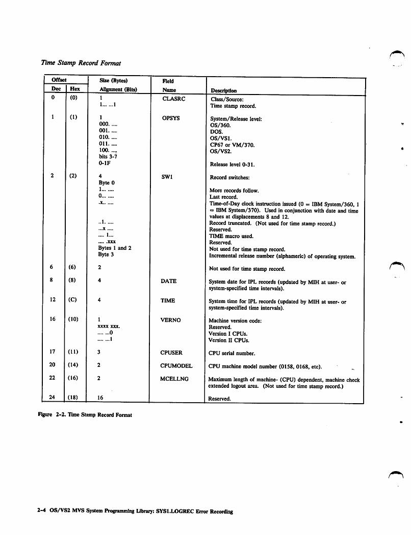
Time Stamp Record Format
Offset Size (Bytes) Field
Dec Hex Alignment (Bits) Name Description0 (0) 1
1 1CLASRC Class/Source:
Time stamp record.
1 (1) 1
000
001
010
01 1
100
bits 3-7
0-lF
OPSYS System/Release level:OS/360.DOS.
OS/VSl.CP67 or VM/370.OS/VS2.
Release level 0-31.
2 (2) 4
Byte 01
0
•X
..1
...X ....
.... 1...
XXX
Bytes 1 and 2Byte 3
SWl Record switches:
More records follow.
Last record.
Time-of-Day clock instruction issued (0 = IBM System/360, 1= IBM System/370). Used in conjunction with date and timevalues at displacements 8 and 12.Record truncated. (Not used for time stamp record.)Reserved.
TIME macro used.
Reserved.
Not used for time stamp record.Incremental release number(alphameric) of operating system.
6 (6) 2 Not used for time stamp record.
8 (8) 4 DATE System date for IPL records (updated by MIH at user- orsystem-specified time intervals).
12 (C) 4 TIME System time for IPL records (updated by MIH at user- orsystem-specified time intervals).
16 (10) 1
XXXX XXX.
0
1
VERNO Machine version code:
Reserved.
Version I CPUs.
Version II CPUs.
17 (11) 3 CPUSER CPU serial number.
20 (14) 2 CPUMODEL CPU machine model number (01S8, 0168, etc).
22 (16) 2 MCELLNG Maximum length of machine- (CPU) dependent, machine checkextended logout area. (Not used for time stamp record.)
24 (18) 16 Reserved.
Figure 2-2. Time Stamp Record Format
2-4 OS/VS2 MVS System Programming Library: SYSl.LOGREC Error Recording

r\
Frame Record Format
Frame Record
If requested via PARM=s'FRAMES* while running the IFCDIPOO serviceaid, Frame Records will be written to the SYSl.LOGREC data setfollowing the Time StampRecord. The Record Entry Area address in theSYS1.LOGREC Header Record will point to the last Frame Record andnot to the Time Stamp Record.
Frames are used by service aid IFCEREPl to edit MCH and CCH recordsfrom CPUs which support a Service Record File (SRF).
Offset Size (Bytes) Field
Dec Hex Alignment (Bits) Name Descriptiim
0 (0) 1
1.1
1.11 ....
CLASS
Machine Check Frames.
Channel Check Frames.
1 (1) 1
001
010
01 1
100
bits 3-7
0-lF
OPSYS System/Release level.DOS.
OS/VSl.VM/370.0S/VS2.Release level 0-31.
2(2) SW
1
0
.XXX ....
.... 1...
Record switches.
More records follow.
Last record.
Reserved.
Time macro used.
3 (3) 3 Reserved.
6 (6) 1 SEQNO Sequence number of physical record in logical set.
7 (7) 1 Reserved.
8 (8) 4 DATE Date of record generation.
12 (C) 4 TIME Time of record generation.
16 (10) 1 VERNO Machine version number.
17 (11) 3 CPUSER CPU serial number.
20 (14) 2 CPUMODEL CPU machine model number (for example, 3033).
22 (16) 2 MCELLNG Maximum length of machine check extended logout area.
24 (18) 1920 FRAME Edit instruction text.
F^ure 2-3. Frame Record Format
Chapter 2. Iidtiafiziiig and Reallocating the SYS1.LOGREC Data Set (IFCDIPOO) 2-5

Reinitializiiig SYS1.LOGRECYou can use IFCDIPOO, controlled by job control language statements, toreinitialize the SYSl.LOGREC data set. IFCDIPOO resets theSYS1.LOGREC header record field that indicates that the entire data setcan be used and clears the time stamp record to hexadecimal zeros.
Example 1: Reinitializing the SYSLLOGREC Data SetIn this example:
• The SYSl.LOGREC data set is reinitialized.
//INSERLOG JOB//STEP1 EXEC PGM=IFCDIPOO//SERERDS DD DSNAME=SYS1.LOGREC,UNIT=3330,// VOL=SER=111111,DISP=(OLD,KEEP)
Control Statements for Example 1
The JOB statement initiates the job; the jobname INSERLOG has nosignificance.
The EXEC statement specifies the program name (PGM=IFCDIPOO).
The SERERDS DD statement specifies the reinitialized output(SYSl.LOGREC) data set (which must be on the system residence volume,VOL=SER=llllll in this example); the ddname must be SERERDS.
Changmg Space Allocation for SYS1.LOGRECThe system generation process determines the size of the SYSl.LOGRECdata set according to the system configuration. If you need to change thesize of the SYSl.LOGREC data set, you can use IFCDIPOO in conjunctionwith the lEHPROGM utility program to increase or decrease the spaceallocation for the SYSl.LOGREC data set.
Note: After scratching and reallocating the data set, the system must bereinitialized because the data set now has a different physical location onthe system residence volume.
Example 2: Chatting Space Allocation for SYS1.LOGRECIn this example:
• The SYSl.LOGREC data set is scratched and uncataloged using thelEHPROGM utility program.
• The SYSl.LOGREC data set is reinitialized and reallocated with newspace specifications using IFCDIPOO.
//RELGREC JOB//SCR EXEC PGM=IEHPROGM//SYSPRINT DD SYSOUT=A//DDI DD UNIT=3330,V0LUME=SER=111111,DISP=OLD//SYSIN DD ♦ "
SCRATCH DSNAME=SYS1.LOGREC,VOL=3330=111111UNCATLG DSNAME=SYS1.LOGREC
/♦//R EXEC PGM=IFCDIPOO//SERERDS DD DSNAME=SYS1.LOGREC,UNIT=3330// VOL=SER=111111,SPACE=(TRK,(10),,CONTIG),// DISP=(NEW,CATLG)
2-6 OS/VS2 MVSSystem Ptogramndtig Library: SYSl.LOGREC Error
Control Statements for Example 2
The first EXEC statement specifies the program name(PGM=IEHPROGM).
The SYSPRINT DD statement defines the output (printer assumed) dataset.
The DDI DD statement defines a permanently mounted volume (thesystem residence volume, VOL=SER=llllll, is considered permanently
? mounted). The ddname DDI is arbitrary.
The SYSIN DD statement indicates that input in the form of controlstatements follows.
' The SCRATCH control statement defines the data set (SYSl.LOGREC)and the direct access volume (VOL=3330=111111) where the data set isto be scratched.
The UNCATLG statement indicates that the data set name(SYS1.LOGREC) is to be removed from the lowest index level of thecatalog.
The second EXEC statement specifies the program name(PGM=IFCDIPOO).
The SERERDS DD statement specifies (1) the location and (2) the size ofthe reinitialized, output (SYSl.LOGREC) data set (requesting contiguoustracks); the ddname must be SERERDS.
Note: If you use the preceding procedure and an uncorrectable channelerror occurs after the SYSl.LOGREC data set has been scratched, butbefore it has been reallocated, the IFCDIPOO job is terminated, and thesystem is marked ineligible for IPL procedures. To solve this problem, doone of the following:
• Use the IBCDMPRS utility program to restore the system and therebyrestore the SYSl.LOGREC data set. After the SYSl.LOGREC dataset has been restored, you can reinitialize the system and reallocateSYSl.LOGREC (Example 2).
or
• If available, execute the reallocate operation on the data set whilerunning under another operating system.
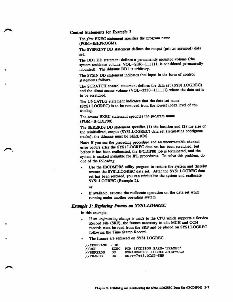
Example 3: R^lacing Frames on SYSELOGRECIn this example:
• If an engineering change is made to the CPU which supports a Service« Record File (SRF), the frames necessary to edit MCH and CCH
records must be read from the SRF and be placed on SYSl.LOGRECfollowing the Time Stamp Record.
« • The frames are replaced on SYSl.LOGREC.
//REPFRAME JOB//REP EXEC PGM=IFCDIPOO,PARM='FRAMES'//SERERDS DD DSNAME=SYS1.LOGREC,DISP=OLD//FRAMES DD UNIT=7443,DISP=SHR
Oinpfor 2. Initializing and Reallocating the SYS1.LOGREC Data Set (IFCDIPOO) 2-7

Control Statements for Example 3
The JOB statement initiates the job; the Jobname REPFRAME has nosignificance.
The EXEC statement specifies the program name (FGMsJFCDlFOO).Keyword specified in FARM field indicates frames are to be read from theService Record File (SRF).
The SERERDS DD statement specifies the reinitialized output(SYSl.LOGREC) data set. The data set is referenced via the systemcatalog. The ddname must be SERERDS.
The FRAMES DD statement spedEed the Service Record FUe (SRF) fromwhich the frames will be obtained. *
Example 4: R^ladng Frames on SYS1.LOGREC on a MuMjnocessorIn this example:
• The frames are replaced on SYSl.LOGREC for a 2-CFU system.
//REPFRMMP JOB//REP EXEC PGM=IFCDIPOO,PARM=FRAMES//SERERDS DD DSN=SYS1.LOGREC,DISP=OLD//FRAMES01 DD UNIT=7443,DISP=OLD//FRAMES02 DD UNIT=7443,DISP=OLD
Control Statements for Example 4
The JOB statement initiates the job; the Jobname REFFRMMF has nosignificance.
The EXEC statement specifies the program name (FGMsIFCDIFOO).Keyword specified in FARM field indicates frames are to be read from theService Record Files (SRFs).
The SERERDS DD statement specifies the reinitialized output(SYSl.LOGREC) data set. The data set is referenced via the systemcatalog. The ddname must be SERERDS.
The FRAMESxx DD statements define the Service Record Files fromwhich the frames will be read (one for each CPU). The last two charactersof each ddname are arbitrary but must be unique. For simplicity andclarity 01 and 02 were chosen.
Note: One SRF for each processor must be online for the allocation tocomplete for this job.
2-8 OS/VS2 MVS System Prograraming Library: SYSl.LOGREC Error Rftpordfag

Chapter 3. Error Recording on SYSl.LOGREC
Records are recorded on SYSl.LOGREC for every hardware or softwarefailure and system condition that has an associated recording request orrecording routine. The records can contain two types of data thatdocument failures and system conditions:
• Error statistics - counts of the number of times that channels, machinemodels, and I/O devices have failed.
• Environmental data - time and circumstances for each failure orsystem condition.
The records are recorded, in chronological order, on SYSl.LOGREC asimdefined length records. In general, each record contains:
Relevant system information at the time of the failure.
Device hardware status at the time of the failure.
Results of any device/control unit recovery attempt.
Results of any software system recovery attempt.
Statistical data.
The recording routines are included as standard programs of the OS/VS2system control program by the system generation process.
Types of Records on SYSl.LOGRECThe SYSl.LOGREC data set, a non-sharable system data set, is apermanent data set that resides on the system residence volume. TheSYSl.LOGREC data set contains:
• A header record.
• A time stamp record.
• Environment records for each failure and system condition that has anassociated recording routine.
• Statistical records that contain counts of the number of times deviceshave failed.
Figure 3-1 shows the recording routines that format and write each type ofrecord on SYSl.LOGREC. Figure 3-2 lists the incidents and the types ofrecords that can be recorded on SYSl.LOGREC for each incident.
Chapter 3. Error Recording on SVSl.LOGREC 3-1

incidents System RecordingRoutines
MachineFailuresCausingProcessor Termination:a CPUa Storagea Storage Keya Timer
Machine Check Handier
a Formats MCH Record
Machine Failurac• CPU
• Storage Key• Tinter
Machine Check Handler
Hardware Error Processor
• Formats MCH Record ^
Channel Failures:a Channel Data Check Channel Check Handier
a Channel Control Checka Interface Control Check
a Formats CCH Record—
IC DDR Swap
Missing Interrupts:• Channel End Pending• Device End Pending
Software Failures;• ABEND (SVCISi• invalid SVC• MCH Software RecoveryAttempt• Program Check• Restart Key Pressed
Incidents on 3704/3705Buffered Log Devices:— Buffer Overflow— Device FailureDevice Failures on TPDevices Attached to3704/3705 Devices
Path Failures Which MayCause Lockouts on Other Paths
• EOD Command• Intermittent or Temporary I/O
Device Failure• Permanent Channel and TP or
I/O Device Failures• Statistical Counter Overflow
Incidents on BufferedLog Devices:• Buffer Overflow• Device Failures
_PaginjJ/Oj|rror_
System Termination (EOD C^ommartd)
System Initialization (iPL)
34(X) Demounts:• EOD Commar>d• CLOSE/EOV Request• DDR Swap• Deallocate Conditions
Demountson BufferedLogDevice• EODComgjand• -ffaPSE/EQV Request• "TJ5h Swap• Deallocate Conditions
Vary OfflineforMSC
lEHDASDR Demount on:• Buffered Log DASD With
Removable Disk Packs
Ij
DDR Recorder
Formats:• DDR Record
(IGFTMCHK)
MIH Recorder
•FormatsMIH Record
Recording Request Routine
• Formats Software Record
VTAM MDR Recorder
• Formats MDR Record
DASD AlternatePath Recovery
OBR/MDR Recorder
Formats:• Long OBR Record• Short OBR Record• MDR Record
Deferred Incident Recorder
SVC 76
Formats:• EOD Record• Short OBR Record• IPL Record
SVC 91
Formats:• Long OBR Record• MDR Record
Figure 3-1. Wridng Records Onto SYSI.LOGREC
SYS1.L06RECRecotding Routines
MCH EmergencyRecorder
Writes MCH RecordOnto SYS1.L0GRECDequeues and WritesRecords OntoSYS1.L06REC
RecordingRequest Routine
• Queues Record• Posts Recording
Task
Record ng Task
AsynchrDequeue
inouslyRec<^
SVC 76
Writes RecordsOnto
SYS1.L0GREC
Notes:
SYS1.L0GREC
LongOBR
Records
ShortOBR
Records
EOD
RecordsIPL
Records
MDR
RecordsMCH
Records ,
CCH
RecordsMIH
Records
SoftwareRecords
DDRRecords
Buffered log devices - devices attached to acontrol unit with a buffer for recordittg orlogging device^lependenL status and senseinformation.
Temporary failures • device^ependent.intermittent failures defined by the ERPto be recorded on SYS1.L0GREC.
3-2 OS/VS2 MVS System Programming library: SYS1.LOGREC Error PAnnrvftng

Incidents
Record Types
CCH DDR EOD IPL MCH MDR MIH
OBR,Long
OBR,Short
Soft
ware
ABEND 1
Buffer Overflow 1
Channel Control Check 1(A) 2(B)
Channel Data Check 1(A) 2(B)
Channel End (missing)Pending 1(F)
CLOSE Request (Demount) inE) 1*(D)
CPU Failure 1 2
DDR Swap (Demount) 2 me) 1*(D)
Deallocate Condition
(Demount) inE) 1*(D)
Device End (missing)Pending 1(F)
EOD Command (Demount orSystem Termination) 4 3(E) 2(D) 1(H)
EOV Request (Demount) 1*(E) 1*(D)
lEHDASDR (UtilityProgram) Demount 1(C)
Interface Control Check 1(A) 2(B)
Intermittent Failure -
I/O Devices 1*(G) 1*(G)
Invalid SVC Issued 1
IPL (SystemInitialization) 1
Paging I/O Error 1 2(1)
Path Failures 1
Permanent Failure - I/Oand TP Devices 1* 1*
Program Check 1
Restart Key Pressed 1
Statistic Counter
Overflow 1
Statistic Counter
Overflow - TP Devices
and Variable LengthTable Entries 1
Storage Failure 1 2(1)
Storage Key Failure 1 2(1)
Temporary Device Failure l*iG) l^G)
Figure 3-2 (Part 1 of 2). Incident/Record Table
Chapter 3. Error Recording on SYSl.LOGREC 3-3

Incidents
Record Types
CCH DDR EOD IPL MCH MDR MIH
OBR,Long
OBR,Short
Soft
ware
Timer Failure 1
Vary Offline 1*(G)
Numbers in boxes (reading horizontally) indicate;
That a specific record type is created for the incident.
The approximate chronolo^cal creation of the record types, if required, on SYSl.LOGREC.
For example, a permanent channel control check incident generates CCH records (Note A) before generating a long OBR record(Note B).
^Asterisk denotes mutually exclusive, device-dependent records. For example, an EOV request on an IBM 3400 series magnetictape device generates a long OBR record (Note D). The MDR record is ignored (Note E).
Letters in boxes indicate the following:
A. Created one CCH record for each ERP retry attempt for same incident before considering error to be permanent.
B. Created only if condition is permanent (uncorrectable).
C. Created only for devices with a buffered log and removable disk packs (such as the IBM 3330, 3340, 3344, and 38SO).
D. Created only for the IBM 3400 series of magnetic tape devices. For EOD command, created randomly and can precedeshort OBR records or follow MDR records.
E. Created only for devices with buffered logs (such as the IBM 2305, 3330, 3340, 3344, 3350, 3375, 3380, and 3850). ForEOD command, created randomly and can precede or follow short and long OBR records.
F. Created for all devices except 1275 PCU, 1419 PCU, and all teleprocessing devices except the local 3704/3705 and 3791.
G. Created only for those devices having an ERP that records certain intermittent or permanent incidents. (Such as the ERPsfor the IBM 2305, 3330, 3340, 3344, 3350, 3375, 3380, and 3850.)
H. Created randomly; MDR and long OBR records can precede short OBR records.
I. Created only for hard machine failures which indicate recording on SYS1.LOGREC.
F^ure 3-2 (Part 2 of 2). Incident/Record Table
Record Header
All records on SYSl.LOGREC contain a standard 24-byte header followedby data that is specific for the record type and the device type or machinemodel. The header provides the information necessary to identify the typeand origin of the record.
• Type information - which defines the specific type of record, thespecific source of the record, the general reason the record was made,and any special record-dependent attributes (such as record length,content, hardware features, format).
• Origin information - which includes the operating system the recordwas generated on, the generating program, the time and date therecord was generated, the CPU identity, and the CPU serial numberon which the record was generated (for a multiprocessing system thismay not be the CPU on which the incident occurred).
3-4 OS/VS2 MVS System Programming Library: SYSl.LOGREC Error Recordmg

The following list identifies the valid record types or classes (the firsthexadecimal digit, bits 0-3, of the record) and specific record sources(second digit, bits 4-7) which are valid for this OS/VS2 release:
IX Machine Check (MCH record)10 MCH.
13 MCH in multiple storage environment.
2X Channel Check (CCH record)20 CCH.
21 CCH in multiple storage environment.
3X Unit Check (OBR record)30 OBR (unit check).34 TCAM OBR.
36 VTAM OBR.
3A DPA OBR.
4X Software Error (software record)40 Software detected software error.42 Hardware detected software error.
44 Operator detected error.48 Hardware detected hardware error.4F Lost record summary.
SX System Initialization (IPL record)50 IPL.
6X Reconfiguration (DDR record)60 DDR.
7X Missing Interruption (MIH record)70 Missing interruption handler.
8X System Termination (HOD record)80 HOD.
81 Machine forced termination. (Restart not possible).84 HOD from lOS. (Restart possible.)
9X Non-Standard (MDR record)90 SVC 91.
91 MDR.
AX Machine check frames (MCF records)AO MCF
BX Channel check frames (CCF records)BO CCF
Chapter 3. Error Recording on SYS1.LOGREC 3-5

The format of the data areas represented in this part is:
Offset
Dec Hex
Offset
Dec Hex
Size
Alignment
Field Name
Description
Size (Bytes)Alignment (Bits)
Field
Name Description
The numeric address of the field relative to the beginning of the data
The first number is the offset in decimal, followed by the hexadecimalequivalent in parentheses. Example: 16 (10).
The field size in bytes.
This column also shows the bit settings of switch fields; the alignm.entor state of the bits in a byte is as follows:
The eight bit positions (0-7) in a byte. For ease ofscanning, the high-order (left-hand) four bits areseparated from the low-order four bits.
X... .... A reference to bit 0.
1... .... Bit zero is on.
0... .... Bit zero is off.
..XX A reference to bits 6 and 7.
Significant bit settings are shown and described. Reserved bitsdescribe bit settings that are not significant for this release. (Usersshould not use the reserved bits because the program may use them infuture releases.)
A symbol that identifies the field.
The use of a field. Where the field's use relates directly to a valuecoded by a user, the coded value is shown. Where the hexadecimalcode for a particular bit setting would be helpful, it is shownseparated from the rest of the description.
Recording Channel Inboard (CCH) RecordsCCH records (Figure 3-3) are recorded on SYSl.LOGREC for everychannel failure (channel control check, channel data check or interfacecontrol check) that does not terminate system operation. If a channelfailure occurs during execution of a command or on the interruptionfollowing command execution, the I/O supervisor suspends normalprocessing and passes control to the channel check handler (CCH). CCHdoes the following:
Analyzes the failure from information stored by the channel.
Stores the results of its analysis in the error recovery procedureinterface block (ERPIB) for the device-dependent error recoveryprocedures (ERPs).
Formats a record containing channel-dependent error information.
Puts the record into a record buffer to be written to SYSl.LOGREC
after finishing its analysis of the channel error.
Formats an error message.
Invokes the recording request routine which queues the CCH recordon the asynchronous output queue and posts the asjmchronousrecording task.
3-6 OS/VS2 MVS System Progranuning libnury: SYSl.LOGREC Error Recording

The recording task asynchronously scans the output queue, issues SVC 76to write any records on this queue to SYSl.LOGREC, and issues any errormessages to the system operator.
If CCH determines that it cannot analyze the channel detected error (suchas when the channel does not store valid channel data or a valid extendedCSW), it passes control to the I/O restart function of the I/O supervisor.I/O restart attempts to restore the failing channel by restarting the I/Ooperation on the entire channel.
If CCH determines that the failure can be retried, it passes control to theI/O supervisor to schedule a device-dependent ERP. The ERP uses theinformation provided in the ERPIB to retry the channel operation. If theretry attempt by the ERP is unsuccessful, CCH creates another CCHrecord. Thus, more than one CCH record can be recorded onSYS1.LOGREC to document the same channel failure. However, if CCHdoes not have a record buffer available to hold the record, it bypasses errorrecording and does not put a record on SYSl.LOGREC to document eachERP retry attempt.
If CCH determines that the failure is too severe to be retried, it passescontrol to the I/O supervisor to schedule a device-dependent ERP. TheERP, as indicated by the I/O supervisor, does not retry the channeloperation, but considers the error to be permanent (uncorrectable) and alsorecords it on SYSl.LOGREC as a long OBR record.
Consult 0S/VS2 MVS System Logic Library, Volume 7 for a detaileddescription of the channel check handler.
Channel Inboard (CCH) Record Format
Offset Size (Bytes)
Alignment (Bits)
Held
Name DescriptionDec Hex
0 (0) 1 LRBHTYPE Class/Source;..1 CCH record.
..1. ...1 CCH record recorded in multiple virtual storage environment.(For VS2 Release 2 and any subsequent VS2 releases.)
..1. 1... SERl (not used by VS).
..1. 1..1 SERO (not used by VS).
1 (1) 1 LRBHSYS System/Release level:000 OS/360.001 DOS.
010 OS/VSl.Oil CP67 or VM/370.100 OS/VS2.bits 3-7
0-lF Release level 0-31.
Figure 3-3 (Part 1 of 4). CCH Record Format
Chapter 3. Error Recording on SYS1.LOGREC 3-7

Offset Size (Bytes)
ABgnment (Bits)
Field
Name Desci^tionDec Hex
2 (2) 1 LRBHSWO Record independent switches:1 More records follow.0 Last record..X Time-of-Day clock instruction issued (0 » IBM System/360 1
= IBM System/370). Used in conjunction with ^te and timevalues at displacements 8 and 12.
..1 Record truncated. (Not used for CCH record.)
...X .... Reserved.
.... 1... TIME macro used.XXX Reserved.
3 (3) 3 LRBHSWl Record dependent switches:Byte 01 Operator message required..1 Record incomplete...X Reserved....1 .... Channel unsupported or failed to log..... 1... niegal CUA.
I.. Portion of data overlaid.1. ERP in progress.X Reserved.
Byte 1 LRBHSW2 CCH internal switches from PCCA:1 Command register parity is valid..1 No recording by CCH...1 CCH FRR in FRR stack.
...1 .... Record SYSl.LOGREC record only.
.... 1... Attention bit in CSW is on.1.. ERPIB has already been created for error.1. UCB is invalid.
X Reserved.
Byte 2 LRBHSW3 CCH interval switches from PCCA:
1 I/O restart function required..1 Alternate return to I/O supervisor requested (CCH retry not
required)...1 Channel analysis module is unavailable to CCH to analyze
error.
...1 .... Channel failed to log.
.... 1... Channel availability table (CAT) entry is valid, but channeltype is not recognized.
1.. Channel reconfiguration hardware (CRH) active on channel attime of channel error.
XX Reserved.
6 (6) 1 LRBHCNT Record count:
bits 0-3 Sequence number of this physical record.bits 4-7 Total number of physical records in this lo^cal record.
7 (7) 1 Reserved.
8 (8) 4 LRBHDATE System date of failure.
12 (C) 4 LRBHTIME System time of failure.
Figure 3-3 (Part 2 of 4). CCH Record Format
3-8 OS/VS2 MVSSystemProgramming lilnary: SYSl.LOGREC Error Recording

Offset
Dec
16
17
20
22
24
32
48
S6
64
Hex
(10)
(11)
(14)
(16)
(18)
(20)
(30)
(38)
(40)
68 (44)
Size (Bytes)
Alignment (Bits)
1
XXXX XXX.
0
1
16
8
8
4
Figure 3-3 (Part 3 of 4). CCH Record Format
Field
Name
LRBHCPID
LRBHCSER
LRBHMDL
LRBHMCEL
LRBCJOB
LRBCAIO
LRBCFCCW
LRBCFCSW
LRBCECSW
LRBCDEVT
Description
Machine version code:
Reserved.
Version I CPUs.
Version n CPUs.
CPU serial number equals zero.Note: If bit S of switch 2 (offset S of LRBHSW3) is set,indicating channel reconfiguration hardware (CRH) is active,the following information is applicable (for IBM Mod 168 MPCPUs only):
1. The CPU serial number field (offset 17 decimal) is thatof the "live" or running CPU and not that of the CPU towhich the channel is actually attached (i.e., the "dead"CPU).
2. The channel set ID and channel status fields of the MP
information area (offset 88 decimal plus a variable logoutlength identified by labels LRBCMPPA andLRBCMPCS) always reflect the address and channelstatus of the channel set connected to the dead CPU.
That is, the first entry for these fields is for the deadCPU, and the second entry is for the iive CPU (the oneon which CRH receives control).
CPU machine model number (0158, 0168, etc).
Maximum length of machine- (CPU) dependent, machine checkextended logout area.
Alphameric name assigned to job (as identified, for example, bya jobname on a JCL JOB statement) being executed and/orrequesting service at time of channel detected error.
List of active I/O units or addresses, one to eight devices, onfailing channel that were found to be busy (device endoutstanding). List includes device address associated withfailure.
Last real CCW executed before failure.
Contents of CSW that were stored following detection of I/Ofailure.
Contents of extended CSW or last four bytes of ERPIB for28xx channels.
Device type (from UCB) associated with failing device.
Chapter 3. Error Recording on SYSl.LOGREC 3-9

Offset Size (Bytes)
Alignment (Bits)
Field
Name DescriptionDec Hex
72 (48) 1 LRBCCHID Channel ID associated with failing channel:
Code Meaning00 Channel Unknown (CCH defaults to provide a ISSII
channel analysis assuming channel adheres toSystem/370 channel design)
01 IntegratedMultiplexor (MPX)
02 Integrated Selector03 Integrated Block MPX05 Standalone Selector
(2860)06 Standalone MPX
(2870)07 Standalone Block MPX
(2880)08 Selector Channel
(2880)OA Integrated File
AdaptorOF Channel Unknown
73 (49) 1 Reserved.
74 (4A) 2 LRBCCUA2 CUA for channel and unit being used at time of failure.
76 (4C) 2 LRBCHCUA CUA, right justified, as stored by hardware in machine storagelocations 185-187 (decimal).
78 (4E) 2 LRBCLOGL Length of channel logout starting at displacement 80.
80 (50) variable LRBCCLOG Machine-dependent, channel logout associated with failure thatcaused channel failure. Logout size is model and channeldependent:
Channel Length(bytes)2860 24
2870 24
2880 112
145/148 96 (maximum)15511/158 0165n/168 03081 8
303X 576
4341 0
2 LRBCFT CCH footprints:4 Reserved.
2 LRBCMPNO Number of online channel sets.
variable LRBCMP Multiprocessing information that consists of a variable numberof fields with LRBCMPPA, LRBCMPCS format. Number offields corresponds with number of online channel sets describedin LRBCMPNO field.
Note: The foliowing two fields, LRBCMPPA and LRBCMPCS, represent a foiinat which is repeated a variable number of timeswithin LRBCMP field. However, first LRBCMPPA, LRBCMPCS format belongs to channel set with failing channel.
2 LRBCMPPA Channel set ID for failing channel (MVS only).2 LRBCMPCS Channel status for eaeh channel (0-15) associated with system.
Each channel, be^nning with ehannel 0 as high order bit, isrepresented by a one-bit code (0 a online, 1 = offline). |
Figure 3-3 (Part 4 of 4). CCH Record Format
3-10 OS/VS2 MVS System Programming Ubrary: SVS1.LOGREC Error Recording

Recording Dynamic Device Reconfiguration (DDR) RecordsDDR records (Figure 3-4) are recorded on SYSl.LOGREC for eachoperator- or system-initiated swap between direct access and magnetic tapedevices and for each operator-initiated swap on a unit record device. Thesystem requests DDR after a permanent (uncorrectable) I/O error hasoccurred. The operator can request DDR at any time by issuing the SWAPcommand.
DDR invokes the DDR recorder to document the devices involved in aDDR swap. The DDR recorder obtains such information to format a DDRrecord as the 'FROM' and 'TO' device addresses, the device type, and, fordirect access devices, the physical address of each disk drive involved in theswap. After formatting the information, the DDR recorder passes controlto the recording request routine which queues the DDR record on theasynchronous output queue and posts the asjmchronous recording task.The recording task asynchronously scans the output queue and issues SVC76 to write any records on this queue to SYSl.LOGREC.
Consult OS/VS2 MVS System Logic Library, Volume 7 for a detaileddescription of dynamic device reconfiguration.
Dynamic Device Reconfiguration (DDR) Record Format
Offset Size (Bytes)
Alignment (Bits)
Field
Name DescriptionDec Hex
0 (0) 1 LRBHTYPE Record key:.11 DDR record.
1 (1) 1 LRBHSYS System/Release level:000 OS/360.001 DOS.
010 OS/VSl.Oil CP67 or VM/370.100 0S/VS2.bits 3-7
0-lF Release level 0-31.
2 (2) 1 LRBHSWO Record independent switches:1 More records follow.
0 Last record.
.X Time-of-Day clock instruction issued (0 = IBM System/360, 1= IBM System/370). Used in conjunction with date and timevalues at displacements 8 and 12.
..1 Record truncated. (Not used for DDR record.)
...X .... Reserved.
.... 1... TIME macro used.
XXX Reserved.
3 (3) 3 LRBHSWl Record dependent switches:Byte 01 Primary storage reconfiguration..1 Secondary storage reconfiguration...1 Operator requested reconfiguration....1 .... Permanent error caused reconflguration..... xxxx Reserved.
Bytes 1 and 2 Reserved.
F^ure 3-4 (Part 1 of 2). DDR Record Format
Chqtter 3. Error Recording on SYSl.LOGREC 3-11

Offset Size (Bytes) Field
Dec Hex Alignment (Bits) Name Description
6 (6) 1
bits 0-3
bits 4-7
LRBHCNT Record count:
Sequence number of this physical record.Total number of physical records in this logical record.
7 (7) 1 Reserved.
8 (8) 4 LRBHDATE System date of failure.
12 (C) 4 LRBHTIME System time of failure.
16 (10) 1
XXXX XXX.
0
1
LRBHCPID Machine version code:
Reserved.
Version I CPUs.
Version H CPUS.
17 (11) 3 LRBHCSER CPU serial number.
20 (14) 2 LRBHMDL CPU machine model number (0158, 0168, etc.).
22 (16) 2 LRBHMCEL Maximum length of machine- (CPU) dependent, machine checkextended logout area. (Not used for DDR record.)
24 (18) 8 LRBRJOB Name of job using 'FROM' device. Field valid only if systeminitiated swap for permanent error or for operator initiated tapeswaps.
32 (20) 6 LRBRVOLl VOLSER ID of volume mounted on 'FROM' swap device.
38 (26) 6 LRBRV0L2 VOLSER ID of volume mounted on 'TO' swap devices. Fieldis zero if no volume is mounted on 'TO' device.
44 (2C) 1 LRBRPHl Physical ID of device (not address). DASD only.
45 (2D) 3 LRBRCUAl Primary CUA of 'FROM' device.
48 (30) 4 LRBRDEVl Device type of 'FROM' device.
52 (34) 1 LRBRPH2 Physical ID of 'TO' device.
53 (35) 3 LRBRCUA2 Primary CUA of 'TO' device.
56 (38) 4 LRBRDEV2 Device type of 'TO' device.
Figure 3-4 (Part 2 of 2). DDR Record Format
Recording Machine Check (MCH) RecordsMCH records (Figure 3-5) are recorded on SYSl.LOGREC whenever thefollowing machine failures occur:
• CPU (processor).• Storage.• Storage key.• Timer.
When a machine failure occurs, the machine check handler (MCH) receivescontrol via a machine-chebk interrupt for a soft failure (one that was
3-12 OS/VS2 MVS System Programming Library: SVSl.LOGREC ErrorRecording

corrected by the hardware retry features: hardware instruction retry (HIR)or error checking and correction (ECC) or for zhard failure (one thatcould not be corrected by HIR and ECC).
Soft Failmes
If the machine-check interrupt is for a soft failure, MCH uses theenvironmental and model independent information describing the failure tobuild an MCH record. After formatting the information, MCH passescontrol to the recovery termination manager (RTM). RTM then invokesthe recording request routine which queues the MCH record on theasynchronous output queue and posts the asynchronous recording task.The recording task asynchronously scans the output queue and issues SVC76 to write any records on this queue to SYSl.LOGREC.
Note: The MODE command can be used to limit the number of MCHrecords that are recorded on SYS1.LOGREC for system recovery (SR) anddegradation (DG) machine check interruptions. This command allows somerecords to be recorded on SYSl.LOGREC for diagnostic purposes, butprevents SYSl.LOGREC from becoming filled with records which describefailures that have already been detected and corrected by HIR and ECC.
Hard Failures
If the machine-check interrupt is for a hard failure, MCH analyzes theinformation in the model independent logout area, isolates the error, andprovides a record of this analysis to RTM. RTM invokes the recordingrequest routine which queues the MCH record on the asynchronous outputqueue and posts the asynchronous recording task. This task asynchronouslyscans the output queue and issues SVC 76 to write any records on thisqueue to SYSl.LOGREC. Before writing these records, RTM inserts anerror identifier (errorid) at the end of each record. RTM inserts the sameerrorid in the software record(s) and SVC dump output (if any) associatedwith this particular error. The errorid also appears in the console messagethat indicates an SVC dump was taken. (See OSIVS2 System ProgrammingLibrary: Service Aids for information on SVC dumps; see OS/VS MVSMessage Library: VS2 System Message for information on consolemessages.) Because the same errorid appears in various pieces ofdiagnostic data, the diagnostician can correlate all available information thatpertains to a particular error.
The error identifier has the form:
SEQxxxxx CPUyy ASIDzzzz TIMEhh.mm.ss.t
where:
xxxxx sequence number
yy logical CPU identifier
zzzz address space identifier
hh.mm.ss.t time stamp (hours, minutes, seconds, tenths of seconds)
With each IPL, the system begins a sequential count of errors. Thesequence number is therefore unique for each software error or machinefailure. It indicates which number this is since the most recent IPL. The
sequence number remains constant for subsequent software recordsassociated with the same error, although the time stamp may change.
Chapter 3. Error Recording on SYSl.LOGREC 3-13

Note: If a SYSl.LOGREC record has no associated error identifier, themessage NO ERRORID ASSOCIATED WITH THIS RECORD is printedwhere the error identifier normally would be found.
If the failure is going to cause processor (CPU) termination and the systemhas only one CPU, MCH collects environmental, model independent, andmodel dependent information to describe the failure. After formatting theinformation, MCH passes control to the MCH emergency recorder to writethis information on SYSl.LOGREC as an MCH record and issues a
message to the system operator. Then, before the system enters a waitstate, the MCH emergency recorder scans the asynchronous output queueand writes any records on that queue to SYSl.LOGREC. Byte 3 of theMCH record format indicates that the failure resulted in systemtermination.
If, in a multiprocessing (MP) system, a processor termination failure occursin one CPU, MCH invokes the alternate CPU recovery routine (ACR) onanother CPU. ACR stores the status of the failing CPU and initiates RTMto process and record the error as a hard failure that does not causeprocessor termination.
If CPU failure occurs when channel reconfiguration hardware (CRH) isactive in an IBM System/370 Model 168 MP environment or when channelset switching (CHS) is available, CRH/CHS enables the operative CPU tocontrol the channels and to solicit interrupts from the channels of theinoperative CPU.
Note: System damage will be recorded as a hard error (byte 33 bit 3) andnot a terminating error (byte 32 bit 6).
Consult OS/VS2 MVS System Logic Library, Volume 7, for a detaileddescription of the machine check handler. Consult IBM System/370Principles of Operation for a detailed description of the machine checkinterruption code shown in the MCH record format.
Machine Check (MCH) Record Format
Offset Size (Bytes)
Alignment (Bits)
Field
Name DescriptionDec Hex
0 (0) 1 LRBHTYPE Class/Source:...1 .... MCH record.
...1 ..1. Converted MCH record (not used by VS).
...1 ..11 LRBHMCH MCH record recorded in multiple virtual storage environment.(For VS2 Release 2 and any subsequent VS2 releases.)
...1 1... SERl (not used by'VS).
...1 1..1 SERO (not used by VS).
...1 1.1. Converted SERl (not used by VS).
...1 1.11 Converted SERO (not used by VS).
1 (1) 1 LRBHSYS System/Release level:000 OS/360.001 DOS.
010 OS/VSl.Oil CP67 or VM/370.100 OS/VS2.bits 3-7
0-lF Release level 0-31.
Figure 3-5 (Part 1 of 4). MCH Record Format
3-14 OS/VS2 MVS System Programming Library:SYSI.LOGREC Error Recording

Offset Size (Bytes)
Alignment (Bits)
Field
Name DescriptionDec Hex
2 (2) 1 LRBHSWO Record independent switches:1 More records follow.
0 Last record.
.X Time-of-Day clock instruction issued (0 = IBMSystem/360, 1= IBM System/370). Used in conjunction with date and timevalues at displacements 8 and 12.
..1 Record truncated. (Not used for MCH record.)
...X .... Reserved.
.... 1... TIME macro used.
XXX Reserved.
3 (3) 3 LRBHSWl Record dependent switches:Byte 0XX Not used by MCH record...1 System terminated by MCH....1 .... Record contains an errorid.
.... xxxx Not used by MCH record.Byte 1 LRBMACT Buffer contains a record to be recorded on SYSl.LOGREC or
moved to another buffer.
Byte 2 LRBMCLB MCH SYSl.LOGREC record buffer overlaid with anotherrecord. If this byte is X'FF', SVC 76 does not record thisrecord on SYSl.LOGREC.
6 (6) 1 LRBHCNT Record count:
bits 0-3 Sequence number of this physical record.bits 4-7 Total number of physical records in this logical record.
7 (7) 1 Reserved.
8 (8) 4 LRBHDATE System date of failure.
12 (C) 4 LRBHTIME System time of failure.
16 (10) 1 LRBHCPID Machine version code:
xxxx XXX. Reserved.
0 Version I CPUs.
1 Version II CPUs.
17 (11) 3 LRBHCSER CPU serial number.
20 (14) 2 LRBHMDL CPU machine model number (0158, 0168, etc.).
22 (16) 2 LRBHMCEL Maximum length of machine- (CPU) dependent, machine checkextended logout area.
24 (18) 4 LRBMLNH Length of record for SYSl.LOGREC.
28 (IC) 4 LRBMWSC Wait state code.
32 (20) 4 LRBMCEIA Machine check error indication area.
Byte 0 LRBMTERM Terminal error switches:
XXX Reserved.
...1 .... LRBMTSEC Secondary error.
.... 1... LRBMTCKS Check stop.1.. LRBMTWRN Power warning.
1 LRBMTINV Invalid logout.X. Reserved.
Byte 1 LRBMHARD Hard machine error switches:
1 LRBMHHRD Hard error assumed.
...1 .... LRBMHSD System Damage.
.XX Reserved.
Figure 3-5 (Part 2 of 4). MCH Record Foimat
Chapter 3. Error Recording on SYSl.LOGREC 3-15

Offset Size (Bytes) Field
Name DescriptionDec Hex Alignment (Bits)
.... 1... LRBMHINV Register or PSW invalid.1.. LRBMHSTO Hard storage error.1. LRBMHSPF Hard storage protection key error.1 LRBMHIPD Instruction processing damage.
Byte 2 LRBMINTM Intermediate error switches:xxxx .... Reserved..... 1... LRBMITOD TOD clock error.
1.. LRBMICKC Clock comparator error.1. LRBMICTM CPU timer error.1 LRBMIL80 Interval timer error.
Byte 3 LRBMSOFT Soft machine error switches:1 LRBMSSFT Soft error assumed..XXX .... Reserved..... 1... LRBMSEXD External damage.
1.. LRBMSECC ECC corrected storage error.1. LRBMSHIR HIR corrected processor (CPU) error.1 LRBMSBUF Buffer error.
36 (24) 1 LRBMPDAR PDAR (program damage assessment and repair) data suppliedby RTM:
XXX Reserved....1.... LRBMINVP Storage reconfigured - page invalidated..... 1... LRBMRSRC Storage reconfiguration status available at displacement 37.
1.. LRBMRSRF Storage reconfiguration not attempted.XX Reserved.
37 (25) 2 LRBMRSR Storage reconfiguration status:Byte 0 LRBMRSRlXXXX XX.. Reserved.
1. LRBMSER Storage error was already set in frame.1 LRBMCHNG Frame had change indicator on.
Byte I LRBMRSR2
1 LRBMOFLN Frame offline or scheduled to go offline..1 LRBMINTC Intercept - frame scheduled to go offline, has a permanent
storage error or scheduled for V = R status...1 LRBMSPER Permanent error occurred in frame....1 .... LRBMNUCL Frame contains permanently resident system storage..... 1... LRBMFSQA Frame is in use for SQA.
1.. LRBMLSQA Frame is in use for LSQA.1. LRBMPGFX Frame contains page fixed data.1 LRBMVEQR Frame is in use for V = R or scheduled for V s= R.
39 (27) 1 LRBMPWL Length of checking block used by machine model.
40 (28) 8 LRBMMOSW Machine check old PSW from storage locations 48-55.
48 (30) 8 LRBMCIC Machine check interruption code (from storage locations232-239) as stored by hardware routines at time of machinecheck:
Byte 01 LRBMFSD System damage..1 LRBMFPD Processing damage...1 LRBMFSR System recovery....1 .... LRBMFTD Timer damage..... 1... LRBMFCD Clock damage.
1.. LRBMFED External damage.X. Reserved.
1 LRBMFDG Degradation.
Figure 3-5 (Part 3 of 4). MCH Record Format
3-16 OS/VS2 MVS System Programming Library: SVSl.LOGREC ErrorRecording

Offset Size (Bytes)
Alignment (Bits)
Field
Name DescriptionDec Hex
Byte 11 LRBMFWN Power warning..XXX XX.. Reserved.
1. LRBMIBU Backed up indicator.1 LRBMIDY Delayed.
Byte 21 LRBMFSE Storage error..1 LRBMFSC Storage error corrected...1 LRBMFKE Key error....X .... Reserved.
.... 1... LRBMVWP PSW EMWP is vaUd.
1.. LRBMVMS PSW masks and key are valid.1. LRBMVPM Program masks and condition code are valid.1 LRBMVIA Instruction address is valid.
Byte 31 LRBMVFA Falling storage address is valid..1 LRBMVRC Region code is valid...X Reserved.
...1 .... LRBMVFP Floating point register is valid.
.... 1... LRBMVGR General purpose register is valid.1.. LRBMVCR Control register is valid.1. LRBMVLG Logout (MCEL) is valid.1 LRBMVST Storage logical is valid.
Byte 41 LRBMNVF LRB may not be valid. Set if PSAMCHIC and
PSAMCHFL=0.
.XXX xxxx Reserved.
Byte 5xxxx XX.. Reserved.
1. LRBMVFT Processor timer is valid.
1 LRBMVCC Clock comparator is valid.Bytes 6 and 7 LRBMCELL Actual length of MCEL data stored for this machine check
interruption.
Z6 (38) 8 Data from storage locations 240-247.64 (40) 4 LRBMFSA Failing storage address from storage locations 248-251.
68 (44) 260 Data from storage locations 252-511.
328 (148) variable LRBMCEL Model dependent machine check extended logout area actuallength in LRBMCELL field. Maximum length in LRBHMCELfield and minimum length is zero. Contains model dependentlogout information. Size is machine dependent:
Model Maximum Length145/148 192 byte~s15511/158 672 bytes165U/168 1416 bytes3031 772 bytes3032 1416 bytes3033 1224 bytes4341 0 bytes3081 0 bytes
variab e 10 ERRORID RTM-generated error identifier consists of:2-byte sequence number2-byte CPU identifier2-byte ASID4-byte time stamp
Figure 3-5 (Part 4 of 4). MCH Record Format
Chapter 3. Error Recording on SYSl.LOGREC 3-17

Recording Miscellaneous Data (MDR) RecordsMDR records (Figure 3-6) are record on SYSl.LOGREC for buffered logdevices whenever the following conditions occur:
• Buffer overflow.
• Demount.
• Device failures.
MDR records are also recorded on SYSl.LOGREC for device failures on
teleprocessing devices connected to an IBM 3704 or 3705 device.
The buffered log devices (devices attached to a control unit with a bufferfor recording or logging device-dependent, status and sense information)are listed in byte four of the MDR record format (Figure 3-6).
Buffer Overflow
If a buffer overflow occurs, the I/O supervisor passes control to adevice=dependent error recovery procedure (ERP). The ERP analyzes theincident and records the device-dependent counter information in thedevice's error buffer. Control passes to the OBR/MDR recorder toreformat the buffered information and to invoke the recording requestroutine. This routine queues the record on the asynchronous output queueand posts the asynchronous recording task. The recording taskasynchronously scans the output queue and issues SVC 76 to write anyrecords on this queue to SYSl.LOGREC.
If a buffer overflow occurs in an IBM 3704 or 3705 device, thedevice-dependent ERP receives control. (This ERP resides in the device,which is a programmable control unit, as part of the network controlprogram.) The ERP then obtains and analyzes information about theincident before asynchronously transferring it to VTAM. When VTAMasynchronously passes control to the VTAM MDR recorder, it formats this3704/3705 information into an MDR record and invokes the recordingrequest routine. This routine queues the record on the asynchronous outputqueue and posts the asynchronous recording task. This task asynchronouslyscans the output queue and issues SVC 76 to write any records on thisqueue to SYSl.LOGREC.
Demounts
If a demount (DDR swap, EOD command, CLOSE/EOV request ordeallocate condition) occurs on an online device with a buffered log (suchas the IBM 2305, 3330, or 3850), the master scheduler or I/O supervisor "invokes SVC 91. SVC 91 formats the sense data from the device's error
buffer and issues SVC 76 to write the information on SYSl.LOGREC as
an MDR record. ?
If a demount by the lEHDASDR utility program occurs, the program hasdetected two disk packs with the same VOLID online on a direct accessdevice with a buffered log and removable disk packs (such as the IBM3330 or 3340). The program causes the one mounted last to be made notready and issues SVC 91 to document the event. SVC 91 formats thesense data from the device's error buffer and issues SVC 76 to write the
information to SYSl.LOGREC as an MDR record.
3-18 OS/VS2 MVS System Programiniiig Ubraiy: SYSl.LOGREC Error Recording

Device Failures
If a device failure occurs, the I/O supervisor passes control to adevice-dependent ERP to analyze the failure, attempt recovery, and storethe device-dependent, status and sense information in the device's errorbuffer. After storing the information, the ERP passes control to theOBR/MDR recorder to reformat the information from the device's errorbuffer and to invoke the recording request routine. This routine queues therecord on the asynchronous output queue and posts the asynchronousrecording task. The recording task asynchronously scans the output queueand issues SVC 76 to write any records on this queue to SYSl.LOGREC.
If a device failure occurs on a teleprocessing device connected to an IBM3704 or 3705 device or on an IBM 3704 or 3705, the respectivedevice-dependent 3704 or 3705 ERP receives control. The ERP analyzesthe incident and asynchronously transfers information to VTAM, whichasynchronously passes control to the VTAM MDR recorder. This recorderformats the information into an MDR record before invoking the recordingrequest routine. This routine queues the record on the asynchronous outputqueue and posts the asynchronous recording task. The recording taskasynchronously scans the output queue and issues SVC 76 to write anyrecords on this queue to SYSl.LOGREC.
Note: If the device-dependent ERP does not define the failure to berecorded by the OBR/MDR recorder as an MDR record, the ERP causesthe OBR/MDR recorder to record the failure as an OBR record.
Miscellaneous Data (MDR) Record Format
Offset Size (Bytes)
Alignment (Bits)
Field
Name DescriptionDec Hex
0 (0) 1 MCLASRC Class/Source:1..1 .... MDR record formatted by SVC 91.1..1 ...1 MDR record.
1..1 ..11 Converted MDR record (not used by VS).
1 (1) 1 MSYSREL System/Release level:000 OS/360.001 DOS.
010 OS/VSl.Oil CP67 or VM/370.100 OS/VS2.bits 3-7
0-lF Release level 0-31.
2 (2) 4 MSWITCHS Record switches:
Byte 01 More records follow.
0 Last record.
.X Time-of-Day clock instruction issued (0 = IBM System/360, 1IBM System/370). Used in conjunction with date and time
values at displacements 8 and 12...1 Record truncated. (Not used for MDR record.)...X .... Reserved.
.... 1... TIME macro used.
XXX Reserved.
Fl^are 3-6 (Part 1 of 3). MDR Record Format
Chapter 3. Error Recording on SYSl.LOGREC 3-19

Offset Size (Bytes)
Alignment (Bits)
Held
Name DescriptionDec Hex
Byte 1X Not used by MDR record..1 Record incomplete...XX xxxx Not used by MDR record.Byte 2
1 IBM 3330.
1. IBM 2305 MOD H.
11 IBM 3277.
1.. IBM 3211.
1.1 IBM 3705.
11. IBM 3670.
Ill IBM 3168.
.... 1... IBM 2715.
.... 1..1 IBM 3340, and 3344.
.... 1.1. IBM 3330 MOD U.
.... 1.11 IBM 3270 dial.
.... 11.. IBM 3800.
.... 11.1 IBM 3895.
.... 111. IBM 3850.
.... 1111 IBM IGAR Diskette.
...1 ...1 IBM 3350.
...1 ..1. IBM 2305 MOD I.
...1 ..11 IBM 3277.*
...1 .1.. IBM 3380. *Device types used to indicate symbolic
...1 .1.1 IBM 3705.* names of devices added to record.
...1 1... IBM 3375.
Byte 30 Two-byte sub-ID field used by record.1 Variable length sub-ID field used by record..XXX .... Reserved.
bits 4-7 Number of characters in sub-ID field of device identified atdisplacement 26.
6 (6) 1 MRCDCNT Record count:
bits 0-3 Sequence number of this physical record.bits 4-7 Total number of physical records in this logical record.
7 (7) 1 Reserved.
8 (8) 4 MDATE System date of incident.
12 (C) 4 MTIME System time of incident.
16 (10) 1 MVERNO Machine version code:
xxxx XXX. Reserved.
0 Version I CPUs.
1 Version n CPUs.
17 (11) 3 MCPUSER CPU serial number.
20 (14) 2 MCPUMOD CPU machine model number (0158, 0168, etc.).
22 (16) 2 MCELLNG Maximum length of machine- (CPU) dependent, machine checkextended logout area. (Not used for MDR record.)
24 (18) 2 BUFRECID Device address of data identified in this record.
Figure 3-6 (Part 2 of 3). MDR Record Format
3-20 OS/VS2 MVS System Programming Library: SVSl.LOGREC Error Recording

Offset Size (Bytes) Field
Dec Hex Alignment (Bits) Name Description
26 (lA) variable BUFSUBID Identification field (2-16 bytes) to identify device atdisplacement 24. Length of this field (2-16 bytes) is defined atdisplacement S.Note: Depending on device, field can denote serial number orCUA of unit.
variable BUFINFO Device-dependent information supplied by ERP that detectederror.
2 MRCTWD Flag bytes from the ROT used to create this record if the newOBR/MDR interface was used.
Figure 3-6 (Part 3 of 3). MDR Record Format
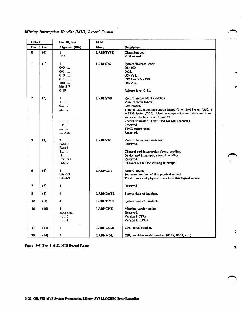
Recording Missing Interruption Handler (MIH) RecordsMIH records (Figure 3-7) are recorded on SYSl.LOGREC for missing(pending) channel end and device end interruptions on all devices exceptthe 1275 PCU, 1419 FCU, and aU teleprocessing devices except local3704/3705 and 3791. The master scheduler, invoked at time intervalsspecified by the user or by the system (default is three minutes), invokesthe missing interruption handler (MIH) to check the UCBs for pendingconditions. If MIH detects a pending condition for the first time, it sets anindicator in the device's UCB. If MIH detects a condition that is still
pending in the device's UCB, it considers the interrupt to be missing anddoes the following:
• Issues a message to the system operator.
• Obtains information about the missing interruption (such as the devicetype, CUA, and time interval used by MIH) to build an MIH record.
• Invokes the recording request routine to queue the MIH record on theasynchronous output queue and post the asynchronous recording task.
The recording task asynchronously scans the output queue and issues SVC76 to write any records on this queue to SYSl.LOGREC.
If MIH detects a missing channel end interruption, or a missing device endon a pa^ng or SYSRES device it also attempts to clear the failingsubchannel by scheduling a service request block (SRB) for the CPU whichissued the I/O request. The SRB causes the I/O supervisor to invoke theI/O restart facility to either schedule a retry for the channel operation ordetermine that the channel error is permanent.
If MIH detects a missing device end interruption, it also determines if thedevice used an alternate path to complete the device end. If this happened,MIH considers the end to be complete and does not create an MIH;otherwise it issues a message to inform the system operator of the missingdevice end.
Consult OS/VS2 MVS System Logic Library, Volume 7, for a detaileddescription of the missing interruption handler.
Giapter 3. Error Recordii^ on SVSl.LOGREC 3-21
Missing Interruption Handler (MIH) Record Format
Offset Size (Bytes)
Alignment (Bits)
Field
Name DescriptionDec Hex
0 (0) 1 LRBHTYPE Class/Source:.111 .... MIH record.
1 (1) 1 LRBHSYS System/Release level:000 OS/360.001 DOS.
010 OS/VSl.Oil CP67 or VM/370.100 0S/VS2.bits 3-7
0-lF Release level 0-31.
2 (2) 1 LRBHSWO Record independent switches:1 More records follow.
0 Last record.
.X Time-of-Day clock instruction issued (0 = IBM System/360, 1= IBM System/370). Used in conjunction with date and timevalues at displacements 8 and 12.
..1 Record truncated. (Not used for MIH record.)
...X .... Reserved.
.... 1... TIME macro used.
XXX Reserved.
3 (3) 3 LRBHSWl Record dependent switches:Byte 0 Reserved.
Byte 11 Channel end interruption found pending..1 Device end interruption found pending...XX .XXX Reserved.
Byte 2 Channel set ID for missing interrupt.
6 (6) 1 LRBHCNT Record count:
bits 0-3 Sequence number of this physical record.bits 4-7 Total number of physical records in this logical record.
7 (7) 1 Reserved.
8 (8) 4 LRBHDATE System date of incident.
12 (C) 4 LRBHTIME System time of incident.
16 (10) 1 LRBHCPID Machine version code:
XXXX XXX. Reserved.
0 Version I CPUs.
.... ...1 Version U CPUs.
17 (11) 3 LRBHCSER CPU serial number.
20 (14) 2 LRBHMDL CPU machine model number (0158, 0168, etc.).
Figure 3-7 (Part 1 of 2). MIH Record Format
3-22 OS/VS2. MVS System Programmii^ Library: SYSl.LOGREC Error ReccNrding

Offset Size (Bytes) Field
Dec Hex Aligiunent (Bits) Name Descr^tion
22 (16) 2 LRBHMCEL Maximum length of machine- (CPU) dependent, machine checkextended logout area. (Not used for MIH record.)
24 (18) 8 LRBNJOB Alphameric name assigned to job (as identified, for example, bya job name on a JCL JOB statement) with an I/O requestpending. If jobname cannot be determined, field is set toblanks.
32 (20) 3 LRBNCUA2 CUA used to address device.
35 (23) 3 LRBNCUAl Primary CUA of device.
38 (26) 6 LRBNVOL VOLSER of volume on device associated with pending I/Orequest.
44 (2C) 4 LRBNDEVT Device type (from UCB) for device associated with pendingI/O request.
48 (30) 8 LRBNINT Time interval (decimal) used by MIH to check for pendingconditions.
56 (38) 24 UCB Common portion.
80 (50) 24 UCB Device dependent section24 bytes for tape and DASD16 bytes for graphics8 bytes for all other devices
Figure 3«7 (Part 2 of 2). MIH Record Format
Recording Output (GBR) RecordsOBR records ( Figure 3-8 and Figure 3-9) are recorded on SYSl.LOGRECfor:
Counter overflow statistics for devices.
Counter overflow statistics and device failures on teleprocessingdevices.
Demount conditions on IBM 3400 series of tape devices.
End-of-day requests.
Paging I/O errors.
Path failures handled by alternate path recovery.
Permanent (uncorrectable or unit check) channel and device failures.
Temporary or intermittent I/O device failures.
Statistical Recording by IFCEREPl program.
Channel Failuns
If a channel failure (channel control check, channel data check or interfacecontrol check) or unit check occurs during execution of a command or onthe interruption following command execution, the I/O supervisor suspendsnormal processing and passes control to the channel check handler (CCH).CCH analyzes the failure, constructs an error recovery procedure interface
Chapter 3. Errw Recording on SYS1.1X>GREC 3-23

block (ERPIB) for the error recovery procedure (ERP), and constructs aCCH record to be recorded on SYSl.LOGREC.
If CCH determines that the I/O operation can be retried, it returns controlto the I/O supervisor. The I/O supervisor then sche^dules adevice-dependent ERP to retry the channel operation.
If the ERP cannot retry the channel operation (because the failure is notretryable or because it has already been retried the specified number oftimes), it passes control sequentially to the following routines:
• The WTO routine which issues a message declaring the error to bepermanent (uncorrectable).
• The statistics update routine which updates the device's statistic ^counter entry in the device statistics table (except for direct accessdevices with buffered logs, such as the IBM 2305, 3330, and 3850).
• The OBR/MDR recorder which formats the device-dependent,environmental and statistical information.
• The recording request routine which queues the long OBR record(Figure 3-8) on the asynchronous output queue and posts theasynchronous recording task.
The recording task asynchronously scans the output queue and issues SVC76 to write any records on the queue to SYSl.LOGREC.
Consult OS/VS2 MVS System Logic Library, Volume 7 for a detaileddescription of the channel check handler and the ERPIB.
Device Failures
If a device failure (unit check) occurs during the execution of a commandor on the interruption following command execution, the I/O supervisorsuspends normal processing and passes control to a device-dependent ERP.The ERP sets the lOB error indicator bits, examines the sense and CSWstatus bits in the lOB to determine the tjrpe of error, and attempts torecover from the error, if possible, by retrying the channel program.
Permanent Failures
If the ERP cannot retry the failure (because the failure is not retryable orbecause it has already been retried the specified number of times), it passescontrol sequentially to the following routines:
• The WTO routine which issues a message declaring the error to bepermanent (uncorrectable).
• The statistics update routine which updates the device's statisticcounter entry in the device statistics table (except for direct accessdevices with buffered logs, such as the IBM 2305, 3330, and 3850).
• The OBR/MDR recorder which formats the device-dependent,environmental and statistical information.
• The recording request routine which queues the long OBR record onthe asynchronous output queue and posts the asynchronous recordingtask.
The recording task asynchronously scans the output queue and issues SVC76 to write any records on the queue to SYSl.LOGREC.
3-24 OS/VS2 MVS System Programming Library:SYSl.LOGREC Error Recording

Temporary Failures
If the ERP is defined to detect and record certain temporary orintermittent, device-dependent failures (such as the ERP for the IBM 2305and 3330 devices which records intermittent bus out, equipment check, andoverrun conditions), it documents the incident on SYSl.LOGREC. TheERP invokes the OBR/MDR recorder to format the device-dependent,statistical and environmental information describing the failure. Afterformatting the information, the OBR/MDR recorder invokes the recording
- request routine which queues a long GBR record on the asynchronousoutput queue and posts the asynchronous recording task. The recordingtask asynchronously scans the output queue and issues SVC 76 to write
s any records on this queue to SYSl.LOGREC. Byte 3 of the OBR recordformat indicates that the record was written because of a temporary failure.
Consult OSfVS2 MVS I/O Supervisor Logic for a detailed description ofthe device-dependent, error recovery procedures.
Paging I/O Errors
If a paging I/O error occurs, the I/O supervisor schedules the DASD ERPto retry the error. If this ERP requires either an operator message or arecord for SYSl.LOGREC or both, it builds a copy of the lOSB (inputoutput supervisor block) in error and the associated EWA (ERP work area)before returning control to the I/O supervisor with a permanent error,corrected error or retry indication. The lOSB and EWA containinformation from the I/O supervisor and ERP associated with the errorwhich the OBR/MDR recorder uses in formatting a long OBR record.
Depending upon the DASD ERP requirements for the error, this ERPqueues the duplicated lOSB and EWA accordingly:
• Operator message - queued onto the asynchronous ERP/WTO queue.
• SYSl.LOGREC record entry - queued onto the asynchronous OBRqueue.
• Operator message and SYSl.LOGREC record entry - queued onto theasynchronous ERP/WTO queue first. After the WTO routine issuesthe message, queued onto the asynchronous OBR queue.
When the OBR/MDR recorder receives control for an OBR recording, itscans the OBR queue, formats a long OBR record for each queued pagingerror, and invokes the recording request routine. This routine queues thelong OBR record on the asynchronous output queue and posts theasynchronous recording task. The recording task asynchronously scans theoutput queue and issues SVC 76 to write any records on this queue to
- SYS1.LOGREC.
Note: If the paging I/O error also invokes software recovery processing, asoftware record can, if indicated, be recorded on SYSl.LOGREC for the
r same incident.
Statistical Recording
Statistics, counts of the number of times I/O devices have failed forspecific, device-dependent failures, are kept in a main storage table calledthe device statistics table. (Note: Intermediate counters for buffered logdevices, such as the IBM 2305, 3330, and 3850 devices, are kept in thedevice's error recording buffer and are updated by the device's ERP. An
Chapter 3. Error Recording on SYSl.LOGREC 3-25

overflow condition or end-of-day (EOD) request on this devices causes theinformation to be recorded on SYSLLOGREC as an MDR record).
Counter Overflow
If any counter for a device with a 10-byte entry in the statistics tablereaches its device-dependent, maximum setting or threshold, the statisticsupdate routine calls the OBR/MDR recorder. The OBR/MDR recorderformats the statistical information from the device's entry in the table intoa short GBR record (Figure 3-9).
If any counter for a device with a variable length statistics table entry (suchas the IBM 3420 and 3886 devices which have a multiple number of10-byte fields in their entries) reaches its threshold, the device-dependentERP calls the OBR/MDR recorder. The OBR/MDR recorder formats thestatistical information from the device's entry in the table and from theother environmental information about the device into a long OBR record.
After formatting the record, the OBR/MDR recorder invokes the recordingrequest routine which queues either a long or short OBR record on theasynchronous output queue and posts the asynchronous recording task.The recording task asynchronously scans the output queue and issues SVC76 to write any records on this queue to SYSl.LOGREC. Byte 3 of theOBR record format indicates that the record was written because of
coimter overflow.
End-of-Day Request
If the operator issues a HALT EOD command, the master schedulerinvokes SVC 76 to search the device statistics table for any counters with anon-zero value. SVC 76 formats a short OBR record for each non-zero
statistic table entry and writes the record to SYSl.LOGREC. For the IBM3400 series of tape devices, SVC 76 issues SVC 91 to format theenvironmental and statistical information that describes each available
(online) tape device. SVC 91 issues SVC 76 to write the information foreach tape device to SYSl.LOGREC as a long OBR record. Byte 3 of theOBR record format indicates that the record was written because of an
end-of-day request.
IFCEREPl Recording
When SYSl.LOGREC is the input data set, the IFCEREPl program mayissue SVC 76 before performing any of the functions specified in theIFCEREPl procedure. SVC 76 records statistical information onSYS1.LOGREC by:
• Creating a long OBR record for each nonzero counter for each device >.with a variable-length entry (10-byte multiples) in the device statisticstable.
• Creating a short OBR record for each nonzero counter for each devicewith a 10-byte length entry in the device statistics table.
• Issuing SVC 91 for each IBM 3400 series magnetic tape device tocreate a long OBR record.
Note; SVC 76 also issues SVC 91 for each buffered log DASD to create anMDR record.
3-26 OS/VS2 MVSSystemProgramming Library:SYS1.LOGREC Error Recording

Teleprocessing Device Recording
For each device in a teleprocessing (TP) system supported by TCAM(telecommunications access method) and for each device in a TP systemsupported by VTAM (virtual telecommunications access method) where thedevice is connected by a channel to the CPU, the access method providestwo counters. TCAM maintains the two counters in the terminal-table
entry. One of these is a two-byte counter that saves the count of theapproximate number of Start I/O (SIO) commands issued for the device orcommunications line (SIO commands issued as a result of retrying duringTCAM's I/O error-recovery procedures are not reflected in the totalcount). The other is a one-byte counter that contains the number of
* temporary errors (defined errors occurring during SIO operations for whichretry was successful) that have occurred since the last error record waswritten on SYSl.LOGREC. If the device for which an SIO operation isbeing performed is known, the counters in the terminal-table entry for thatdevice are updated. The counters in a line entry in the terminal table areupdated only if the station for which the SIO operation is being performedis not known; the counters are reset to zero each time their contents arerecorded on SYSl.LOGREC. Both counters are updated by the TCAMERPs and, when one of these counters reaches its maximum value, theERP calls the OBR/MDR recorder.
VTAM also maintains two counters. One is a two-byte counter that savesthe count of the approximate number of SIO commands issued for thedevice. The other is a one-byte counter that saves the count of temporaryerrors (errors corrected by the VTAM ERPs). The counters are reset tozero each time their contents are recorded on SYSl.LOGREC. Both
counters are updated by the VTAM ERPs and, when one of these countersreaches its maximum value, the ERP calls the OBR/MDR recorder. (Note:Other counters for these devices are also kept in the device statistics tableand are recorded on SYSl.LOGREC as described under "Statistical
Recording" in this publication.) The OBR/MDR recorder formats a longOBR record and invokes the recording request routine. This routine queuesthe record on the asynchronous output queue and posts the asynchronousrecording task. The recording task asynchronously scans the output queueand issues SVC 76 to write any records on this queue to SYSl.LOGREC.Bytes 1 and 3 of the OBR record format indicate that the record waswritten because of counter overflow on a device supported by a TP accessmethod.
Device Failures
If a permanent or temporary device failure (unit check) occurs on a TPdevice supported by TCAM or by VTAM, where the device is connected tothe CPU by a channel, the appropriate access method ERP gives control tothe OBR/MDR recorder. The OBR/MDR recorder formats a long OBR
- record to describe the error and invokes the recording request routine. Thisroutine queues the record on the asynchronous output queue and posts theasynchronous recording task. The recording task asynclu-onously scans theoutput queue and issues SVC 76 to write any records on this queue toSYSl.LOGREC. Bytes 1 and 3 of the OBR record format indicate thatthe record was written because of a temporary failure on a devicesupported by a TP access method.
Chapter 3. Error Recording on SVSl.LOGREC 3-27

3400 Danount Recording
A demount (DDR swap, CLOSE/EOV request, EOD command ordeallocation condition) involving the IBM 3400 series of magnetic tapedevices causes a record to be made describing the device having the tapedemounted. DDR, CLOSE/EOV, EOD, and UNALLOCATE invoke SVC91 to format the environmental and statistical data that describes the tapedrive having the tape demounted. SVC 91 then issues SVC 76 to write theinformation to SYSl.LOGREC as a long OBR record. Byte 3 of the OBRrecord format indicates that the record was written because of a volume
demount.
Note: For 3400 demounts the sense information, failing CCW, and CSWfields of the OBR record formats are not valid.
Outboard (OBR) Record Format - (Long Form)
Offset Size (Bytes)
Al^nment (Bits)
Field
Name DescriptionDec Hex
0 (0) 1 CLASRC Class/Source:..11 .... OBR (unit check) record...11 ..1. Converted OBR record (not used by VS)...11 .1.. TP access method (TCAM) OBR record...11 .11. TP access method (VTAM) OBR record...11 1.1. Dynamic pathing availability (DPA), OBR record.
1 (1) 1 SYSREL System/Release level:000 OS/360.001 DOS.
010 OS/VSl.Oil CP67 or VM/370.100 OS/VS2.bits 3-7
0-1F Release level 0-31.
2 (2) 4 SWITCHES Record Switches:
Byte 01 More records follow.
0 Last record.
.X Time-of-Day clock instruction issued (0 s IBM System/360, 1=3 IBM System/370). Used in conjunction with date and timevalues at displacements 8 and 12.
..1 Record truncated. (Not used for OBR record.)
...X .... Reserved.
.... 1... TIME macro used.
XXX Reserved.
Byte 11 SDR counters dumped at EOD..1 Temporary error...1 Short record.
...1 .... MP system.
.... 0... CPU A (MP system) issued last SIO.
.... 1... CPU B (MP system) issued last SIO.Volume demount.
Not used by OS/VS2.1 SECUA contains polling characters (instead of CUA). Only set
for TP records (BTAM/TCAM).
Figure 3-8 (Part 1 of 3). Long OBR Record Format
3-28 OS/VS2 MVS System Programming Library: SYSl.LOGREC Error Recording

Offset Size (Bytes) Field
Dec Hex Alignment (Bits) Name Description
Byte 2Byte 3
Not used for OBR record.
Channel set ID for failing channel.
6 (6) 1
bits 0-3
bits 4-7
RCDCNT Record count:
Sequence number of this physical record.Total number of physical records in this logical record.
7 (7) 1 Reserved.
8 (8) 4 DATE System date of incident.
12 (C) 4 TIME System time of incident.
16 (10) 1
XXXX XXX.
0
1
VERNO Machine version code:
Reserved.
Version I CPUs.
Version II CPUs.
17 (11) 3 CPUSER CPU serial number.
20 (14) 2 CPUMOD CPU machine model number (0158, 0168, etc.).
22 (16) 2 MCELLNG Maximum length of machine- (CPU) dependent, machine checkextended logout area. (Not used for OBR record.)
24 (18) 8 JOBID Alphameric name assigned to job (as identified, for example, bya jobname on a JCL job statement) being executed and/orrequesting service at time of failure.
32 (20) 8 FAILCCW CCW being executed at time of failure.
40 (28) 8 CSW Contents of CSW that was stored following detection of I/Oerror. Records indicating path failures handled by alternatepath recovery are identified by the unique CSW status ofInterface Control Check plus Channel Control Check.
48 (30) 1 DEVDEPC Count of doublewords which record uses for device dependentdata.
49 (31) 3 SECUA Secondary channel and unit address (actual CUA) associatedwith final retry of failing I/O device. TP polling characters,right justified, channel and unit address (TCAM/BTAM only).
52 (34) 4 DEVTYPE Device type associated with failing device.
56 (38) 1 SDRCNT Number of bytes of statistical data which record uses to recordstatistical data recorder (SDR) work area.
57 (39) 3 PCUA Primary CUA of device being used when failure occurred. ForIBM 2314, 3330, 3340, 3375, or 3380 series of devices, fieldcontains physical location (not address) of failing unit.
60 (3C) 2 lORETRY Number of I/O retries attempted for this error incident.
62 (3E) 2 SENSCNT Number of bytes of data in SENSE field.
Figure 3-8 (Part 2 of 3). Long OBR Record Format
Chapter 3. Error Recording on SYSl.LOGREC 3-29

Offset Size (Bytes) Field
Dec Hex AUgmnent (Bits) Name Description
64 (40) variable DEVDEP Device dependent information.
variable SDRINF SDR counter area that contains statistical counter/indicatordata from device statistics table.
variable SENSE Device-dependent sense information that was received on firstsense command to failing device.
2 RCTWD Flag bytes from the RCT used to create this record if the newOBR/MDR interface was used.
Figure 3-8 (P&rt 3 of 3). Long OBR Record Format
Outboard (OBR) Record Format - (Short Form)
Offset Size (Bytes)
Al^mnent (Bits)
Field
Name DescriptionDec Hex
0 (0) 1 CLASRC Class/Source:..11 .... OBR (unit check) record...11 ..1. Converted OBR record (not used by VS)...11 .1.. TP access method (TCAM) OBR record...11 .11. TP access method (VTAM) OBR record.
1 (1) 1 SYSREL System/Release level:000 OS/360.001 DOS.
010 OS/VSl.Oil CP67 or VM/370.100 0S/VS2.bits 3-7
0-lF Release level 0-31.
2 (2) 4 SWITCHES Record switches:
Byte 01 More records follow.
0 Last record.
.X Time-of-Day clock instruction issued (0 = IBM System/360, 1a IBM System/370). Used in conjunction with date and timevalues at displacements 8 and 12.
..1 Record truncated. (Not used for OBR record.)
...X .... Reserved.
.... 1... TIME macro used.
XXX Reserved.
Byte 11 SDR counters dumped at EOD..1 Temporary error...1 Short record.
...1 .... MP system.
.... 0... CPU A (MP system) issued last SIO.
.... 1... CPU B (MP system) issued last SIO.1.. Volume demount.
X. Not used by OS/VS2.X Reserved.
Byte 2 Not used for OBR record.
Byte 3 Channel set ID for failing channel.
Figure 3-9 (Part 1 of 2). Short OBR Record Format
3-30 OS/VS2 MVS System Ptogramming Uteary: SYS1.LOGREC Error Recording

Offset Size (Bytes) Field
Dec Hex Alignment (Bits) Name Description
6 (6) 1
bits 0-3
bits 4-7
RCDCNT Record count:
Sequence number of this physical record.Total number of physical records in this logical record.
7 (7) 1 Reserved.
8 (8) 4 DATE System date of incident.
12 (C) 4 TIME System time of incident.
16 (10) 1
XXXX XXX.
0
1
VERNO Machine version code:
Reserved.
Version I CPUs.
Version II CPUs.
17 (11) 3 CPUSER CPU serial number.
20 (14) 2 CPUMOD CPU machine model number (0158, 0168, etc.).
22 (16) 2 MCELLNG Maximum length of machine- (CPU) dependent, machine checkextended logout area. (Not used for OBR record.)
24 (18) 4 SDEVTYP Device type associated with failing device.
28 (IC) 1 SSDRCNT Number of bytes of statistical data to be recorded from SDRwork area at displacement 32.
29 (ID) 3 SCUA Primary CUA being used when failure occurred.
32 (20) variable SSDR SDR counter area containing statistical counter/indicator datafrom device statistics table.
Figure 3-9 (Part 2 of 2). Short OBR Record Format
Recording Software RecordsSoftware records (Figure 3-10) are recorded on SYSl.LOGREC for:
• Hardware detected hardware errors such as software recovery attemptsfor hard machine failures.
• Hardware detected software errors such as program checks.
• Operator detected errors such as pressing the restart key.
• Software detected software errors such as ABTERM (CALLRTMmacro) or programs issuing SVC 13 (ABEND) and programs issuingan invalid SVC.
The system control program (SCP) uses functional recovery routines(FRRs) and ESTAE/ESTAI services to attempt recovery from selectedsoftware errors. The FRRs provide recovery for locked SRB (servicerequest block) and supervisor control mode functions. The ESTAE/ESTAIservices provide recovery for enabled, non-locked task mode functions.
For error recording purposes, the FRR and ESTAE/ESTAI services coUecterror data in the system diagnostic work area (SDWA) to assist inidentifying the SCP error and then invoke the recovery termination
Chapter 3. Error RecortBng on SYSl.LOGREC 3-31

Software Record Format
manager (RTM). When the FRR or ESTAE/ESTAI service requests errorrecording for a specific error condition, RTM formats a software recordfrom the following information:
• Standard record header information.
• SDWA information such as registers, PSW, locks held at the time oferror, completion code, data describing reasons and conditions forentering the recovery exit routine, the CSECT in which the erroroccurred, module (microfiche) name, and FRR ID. Consult OS/VS2SPL: Debugging Handbook^ Volume 3 for the detailed format of theSDWA.
• Variable information supplied by the FRR or ESTAE/ESTAI serviceswhich assists in isolating the specific error. A description of thespecific FRR or ESTAE/ESTAI service dependent information is inthe appropriate program listing or program logic manual whichdocuments the program issuing the FRR or ESTAE/ESTAI service.
• Error identifier (errorid) that is added to the record in order tocorrelate this software record with an associated machine check record
or SVC dump.
After formatting the software record, RTM invokes the recording requestroutine. This routine queues the software record on the asynchronousoutput queue and posts the asynchronous recording task. The recordingtask asynchronously scans the output queue and issues SVC 76 to writeany records on this queue to SYSl.LOGREC.
Offset Size (Bytes)
Alignment (Bits)
Field
Name DescriptionDec Hex
0 (0) 1 HDRTYP Class/Source:.1 Software detected software error.
.1.. ..1. Hardware detected software error.
.1.. .1.. Operator detected error.
.1.. 1... Hardware detected hardware error.
.1.. nil Lost record summary.
1 (1) 1 HDROPRN System/Release level:000 OS/360.001 DOS.
010 OS/VSl.Oil CP67 or VM/370.100 OS/VS2bits 3-7
0-lF Release level 0-31.
2 (2) 1 HDRIS Record independent switches:1 More records follow.
0 Last record.
.X Time-of-Day clock instruction issued. Used in conjunction withdate and time values at displacements 8 and 12.
..1 Record truncated. (When IFCEREPl detects this bit being on.it does not edit record but prints it out in hexadecimal.)
Figure 3-10 (Part I of 3). Software Record Format
3-32 OS/VS2 MVS System ProgrammingLibrary:SYSl.LOGREC Error Recording

r\
Offset Size (Bytes) Field
Dec Hex Al^tunent (Bits) Name Description
...X ....
.... 1...
XXX
Reserved.
TIME macro used.
Reserved.
3 (3) 3
Byte 01
.1
..1
...X xxxx
Byte 1Byte 2
HDRDS Record dependent switches:
Short record. (Set for '4F' type records to indicate that recordis not as long as other software records.)Record incomplete. (Record truncated because of lack ofbuffer space.)Record contains an ERRORID.
Not used.
Reserved.
Reserved.
6 (6) 1
bits 0-3
bits 4-7
HDRCNT Record count:
Sequence number of this physical record.Total number of physical records in this logical record.
7 (7) 1 Reserved.
8 (8) 4 HDRTM System date of incident.
12 (C) 4 System time of incident.
16 (10) 1
xxxx XXX.
0
1
HDRCPID Machine version code:
Reserved.
Version I CPUs.
Version II CPUs.
17 (11) 3 CPU serial number.
20 (14) 2 CPU machine model number (01S8, 0168, etc.).
22 (16) 2 Maximum length of machine- (CPU) dependent, machine checkextended logout area. (Not used for software record.)
24 (18) 8 JOBID Alphameric name assigned to job (as identified, for example, bya jobname on a JCL JOB statement) being executed and/orrequesting service at time of failure.
32 (20) 400 SDWA SDWA are detailed by IHASDWA mapping macro. Consult0S/VS2 SPL: Debugging Handbook, Volume 3, for detailedSDWA format. However, area contains FRR orESTAE/ESTAI dependent data such as:
2
4
8
8
4
Byte 01
.1
SDWAABCC
SDWAGRSV
SDWAECl
SDWAAECl
SDWAFLGS
SDWAERRA
SDWAMCHK
SDWAPCHK
ABEND completion code on entry to exit routine.General purpose registers at time of error.Extended control PSW at time of error (ABEND).Additional EC mode information.
Switches describing reasons and conditions for entering arecovery exit routine.Error type causing entry to recovery exit routine.Machine check.
Program check.
F^ure 3-10 (Part 2 of 3). Software Record Format
Chapter 3. Error ReconUiig on SYS1.LOGREC 3-33

Offset
Dec Hex
432
434
variab
(IBO)
(1B2)
Size (Bytes)
Alignment (Bits)
..1
...1 ....
.... 1...
1..
1.
1
Byte 1xxxx ....
.... 1...
1..
1.
1
Byte 21
.1
..1
...1 ....
.... 1...
XXX
Byte 31
.1
..1
.... 1...
1..
1.
24
Bytes 0-7Bytes 8-15Bytes 16-23
2
variable
10
Field
Name
SDWARKEY
SDWASVCD
SDWAABTM
SDWASVCE
SDWATEXC
SDWAPGIO
SDWAERRB
SDWATYPl
SDWAENRB
SDWALDIS
SDWASRBM
SDWAERRC
SDWASTAF
SDWASTAI
SDWAIRB
SDWAPERC
SDWAEAS
SDWAERRD
SDWACLUP
SDWANRBE
SDWASTAE
SDWACTS
SDWAMABD
SDWARPIV
SDWAMCIV
SDWALCPU
SDWARECP
SDWAMODN
SDWACSCT
SDWAREXN
SDWAURAL
SDWAVRA
ERRORm
Figure 3-10 (Part 3 of 3). Software Record Format
Description
Console restart key depressed.Task issued SVC 13.
System forced SVC 13 (ABTERM).SVC issued by a locked or SRB routine.Unrecoverable translation failure.
Page I/O error.Additional error entry information at time of failure.Reserved.
Type 1 SVC was in control.Enabled RB was in control.
Logically of physically disabled routine was in control.System was in SRB mode.Additional error entry information:Previous ESTAE exit or FRR failed.
ESTAI exit previously received control.IRB preceded RB associated with this exit.This recovery routine is being percolated to.Lower level exit recognized error and provided serviceabilityinformation.
Reserved.
Additional error entry information:Recovery routine cleanup only - no retry.RB associated with this ESTAE exit not in control at time of
error.
This ESTAE exit has been entered for a previous ABEND. Notapplicable for FRRs.This task not in control at time of error, but task within samejobstep tree requested ABEND.This task not in control at time of error, but is ancestor ofABENDed task. Used with SDWACLUP Held.
Registers and PSW at time of error unavailable.Machine check error information unavailable.
Reserved.
Logical address of CPU holding requested resource.
Recording parameters:Module name, supplied by recovery routine, involved in error.CSECT name, supplied by recovery routine, involved in error.Name of recovery routine handling error.
Length of variable area containing recovery exit data.
Contains FRR dependent data such as damage assessment,recovery action information, and specific diagnostic informationto assist in isolating or identifying problem. Consult appropriateprogram listing or program logic manual describing programthat issued FRR or recovery exit for a description of specificdata supplied by recovery exit routine.
Error identifler - not part of the SDWA, but located directlyafter the SDWA in the SYSl.LOGREC record. Errorid consists
of:
2-byte sequence number2-byte CPU identifier2-byte ASID4-byte time stamp
3-34 OS/VS2 MVS SystemProgramming Library: SYS1.LOGREC Error Recoiding

Recording System Initialization (IPL) RecordsIPL records (Figure 3-11) are recorded on SYSl.LOGREC to documentsystem initializations. Each master scheduler initialization of the operatingsystem creates one IPL record. The IPL record also provides the user witha way to measure the approximate time interval between the terminationand reinitialization of the operating system.
When the system operator initializes the operating system, the masterscheduler invokes the MIH process which issues the SVC 76. SVC 76obtains system environmental information and the date/time values fromthe time stamp record, formats this information, and writes it onSYSl.LOGREC as an IPL record.
System Initialization (IPL) Record Format
Offset Size (Bytes) Field
Dec Hex Al^nment (Bits) Name Description
0 (0) 1
.1.1 ....
CLASRC Class/Source:IPL Record.
1 (1) 1
000
001
010
01 1
100
bits 3-7
0-lF
OPSYS System/Release level:OS/360.DOS.
OS/VSl.CP67 or VM/370.0S/VS2.
Release level 0-31.
2 (2) 4
Byte 01
0
.X
..1
...X ....
.... 1...
XXX
Bytes 1 and 2Byte 3
swi Record switches:
More records follow.
Last record.
Time-of-Day clock instruction issued (0 = IBM System/360, 1= IBM System/370). Used in conjunction with date and timevalues at displacements 8 and 12.Record truncated. (Not used for IPL record.)Reserved.
TIME macro used.
Reserved.
Not used for IPL record.
Incremental release number (alphameric) of operating system.
6 (6) 2 Not used for IPL record.
8 (8) 4 DATE System date when system was initialized.
12 (C) 4 TIME System time when system was initialized.
16 (10) 1
XXXX XXX.
0
1
CPUSER Machine version code:
Reserved.
Version I CPUs.
Version II CPUs.
17 (11) 3 CPUSERl CPU serial number.
20 (14) 2 CPUMODEL CPU machine model number (01S8, 0168, etc.).
Figure 3-11 (Fart 1 of 2). IPL Record Format
Chapter 3. Enwr Recording on SYSI.LOGREC 3-35

OffsetSize(Bytes)Field
DecHexAlignment(Bits)NameDescription
22(16)2MCELLNGMaximumlengthofmachine-(CPU)dependent,machinecheckextendedlogoutarea.(NotusedforIPLrecord.)
24(18)1SUBSYSIDDevicetypeorprogramthatcausedrestart.SeeFigure3-13.
25(19)3NotusedforIPLrecord.
28(IC)2REASONAlphamericreasonforIPL.SeeFigure3-12.
30(IE)2NotusedforIPLrecord.
32(20)8CHANASSNChanneltypes(0-15)assignedtosystem.Eachchannelisrepresentedbyafourbitcodeinappropriatesub-field:
CodeMeaning0ChannelUnknown(althoughassumeschanneladheres
toSystem/370channeldesign)1IntegratedMultiplexor(MPX)2IntegratedSelector3IntegratedBlockMPX5StandaloneSelector(2860)6StandaloneMPX(2870)7StandaloneBlockMPX(2880)8SelectorChannels(2880)AIntegratedFileAdaptorFChannelUnknown(althoughassumeschanneladheres
toSystem/370channeldesign)
40(28)4HIGHADDRAddressoflastvalidbyteofstoragefoundatIPLtime.Ifsystemhaslargecapacitystorage(LCS),fieldreflectsLCSaddress.
44(2C)4Reserved.
48(30)8LASTACTLastactivitytimeanddatefromtheTimeStampRecord.
Figure3-11(Part2of2).IPLRecordFormat
SpecifyingRDEDuringSystemGeneration
Toincludethereliabilitydataextractor(RDE)optioninyoursystem,specifythekeywordRDEintheOPTIONS=parameterofthesystemgenerationCTRLPROGmacroinstructionasfollows:
CTRLPROG,OPTIONS=(.,RDE,.)
See0S/VS2MVSSystemProgrammingLibrary:SystemGenerationReferenceforacompletedescriptionoftheCTRLPROGmacroinstruction.
Note:ToincludeRDEaftersystemgeneration,eitherthelEBCOPYutilityprogramorthelinkageeditorprocessingprogramcanbeusedtomovethefollowingthreemodulesfromthedistributionlibraries(DLlBs),SYS1.AOSCD,toSYS1.LINKLIB:
IFCRDESMMasIFCRDE03
IFCEIPLOMasIFCEEOD
IFCSIPLOMasIFCSEOD
3-36OS/VS2MVSSystemProgrammingLibrary:SYSl.LOGRECErrorRecording

IPL Recording with RDE
When a system includes the RDE option, the master scheduler invokes theMIH process which issues SVC 76 to issue an operator message (WTOR)during initialization of the operating system. SVC 76 formats the IPLreason code and subsystem ID code supplied by the operator, theenvironment^ information, and the time stamp record values and writes theinformation on SYSl.LOGREC as an IPL record.
SVC 76, to obtain the operator information, issues the following systemmessage:
id IFB010D ENTER 'IPL REASON, SUBSYSTEM ID' or 'U'
Message IFBOIOD requests the operator to provide: (1) the reason for theIPL, and (2) the subsystem (device or program) responsible for the restart.The operator replies to message IFBOIOD by entering the REPLYcommand as follows:
id
IT
ss
REPLY
R
id,'rr,ss'
The identifier of message IFBOIOD.
The IPL reason code which must be entered in capital letters; thereason for starting or restarting the system (Figure 3-12).
The subsystem ID code used with IPL reason codes IE, IM, CE, andME (Figure 3-13). The subsystem ID code for all other IPL reasoncodes is 00.
Chapter 3. Error Recording on SYSl.LOGREC 3-37

Code Reason Description
NM Normal Normal system initialization.
IE IBM hardware/programmingproblem, CE/SE notrequired;
System restarted after a stop caused by a hardwarefailure or IBM programming problem, and a CE/SEwas not required.
IM IBM hardware/programmingproblem, CE/SE required.
System restarted after a stop caused by a hardwarefailure or IBM programming problem, and it wasnecessary for a CE/SE to correct problem.
ME Media An IBM hardware unit failed because of faulty or damaged media(such as a damaged tape or disk).
UN Unknown An undetermined hardware or software failure.
OP Operational An operator error or procedural problem.
UP User program A program other than an IBM supplied system controlprogram or programming product failed in such in a way as to cause asystem restart.
EN Environmental A failure other than hardware/software or operationalcaused system to be restarted (power failure, air conditioning, etc.).
CE CE/SE has system. System restarted at CE/SE request to correctproblem.
Figure 3-12. IPL Reason Codes
ID Subsystem Name Components
00 Null Subsystem is unknown or subsystem code is not required by reason code.
10 Processor CPU, channels (for example: IBM 2860, 2870, 2880), storage units, operatorconsoles (for example: IBM 1052, 2150).
20 Direct Access (DASD) Direct access storage devices (for example: IBM 2301, 2305, 2314, 3330, 3340,3350, 3850 and their control units).
30 Other All devices other than those specified under other subsystem IDs (for example:IBM 2911, 2914, paper tape).
40 Tape Tape devices and their control units (for example: IBM 24xx, 2803, 3410, 3420,3803).
50 Card/Print Card (record unit) and printing devices (for example: IBM 1403, 1442, 2501,2520, 2540, 2821, 3203, 3211, 3800).
60 MICR/OCR Magnetic ink (MICR) and optical (OCR) character recognition devices (forexample: IBM 1287, 1288, 1419).
70 Teleprocessing Teleprocessing devices and their control units (for example: IBM 2701, 2702,2703, 3705).
80 Graphics/Display/Audio Graphic, display, and audio devices (for example: IBM 2250, 2260, 2840, 2848,7770, 7772).
90 IBM System ControlProgram
IBM programming system.
92 IBM Programming Product IBM programming products such as FORTRAN, COBOL, or RPG.
Figure ^-13. Subsystem ID Codes
3-38 OS/VS2 MVS System Programming library: SVSI.LOGREC Error Recording

Invalid reply to IFBOIOD: If the operator's reply to IFBOIOD is incorrect,the system issues the message:
IFB020I INVALID REPLY TO IFBOIOD
The message IFBOIOD is then repeated, and the operator enters either theREPLY command with the proper codes or the REPLY command asfollows:
id
REPLY
R
id, 'U'
The identifier of message IFBOIOD.
U
Assume the default values.
Restart continues after either a valid or 'U' reply; in the case of a 'U*reply, the IPL record is formatted with zeros in the subsystem ID field anda DF in the IPL reason Held.
Recording System Termmatlon (EOD) RecordsEOD records (Figure 3-14) are recorded on SYSl.LOGREC whenever thesystem operator enters the HALT EOD command to terminate theoperating system. The system operator usually issues the HALT EODcommand before the following conditions:
• When the power is turned off.
• When the system is going to enter a long wait state.
Each HALT EOD command invokes the master scheduler to record one
EOD record on SYS1.LOGREC. The master scheduler invokes the MIH
recorder to issue SVC 76. SVC 76 formats the system environmentalinformation and writes it on SYS1.LOGREC as an EOD record.
System Termination (EOD) Record Format
Offset Size (Bytes)
ABgnnient (Bits)
Field
Name DescriptionDec Hex
0 (0) 1 CLASRC Class/Source:1 EOD Record.
1 1 System Termination (Non-Restartable)1... .1.. EOD from lOS (Restartable Wait State)
1 (1) 1 OPSYS System/Release level:000 OS/360.001 DOS.
010 OS/VSl.oil CP67 or VM/370.100 OS/VS2.bits 3-7
0-lF Release level 0-31.
Figure 3-14 (PiBit 1 of 2). EOD Rectmi Fonnat
Chmiter 3. Error Receding CO SYSI.LOGREC 3-39

Offset Size (Bytes) Field
Dec Hex Alignment (Bits) Name Description
2 (2) 4
Byte 01
0
.X
..1
...X ....
.... 1...
XXX
Bytes 1 and 2Byte 3
SWl Record switches:
More records follow.
Last record.
Time-of-Day clock instruction issued (0 =3 IBM System/360, 1a IBM System/370). Used in conjunction with date and timevalues at displacements 8 and 12.Record truncated. (Not used for EOD record.)Reserved.
TIME macro used.
Reserved.
Not used for EOD record.
Incremental release number (alphameric) of operating system.
6 (6) 2 Not used for EOD record.
8 (8) 4 DATE System date of condition.
12 (C) 4 TIME System time of condition.
16 (10) 1
XXXX XXX.
0
1
VERNO Machine version code:
Reserved.
Version I CPUs.
Version II CPUs.
17 (11) 3 CPUSER CPU serial number.
20 (14) 2 CPUMODEL CPU machine model number (0158, 0168, etc.).
22 (16) 2 MCELLNG Maximum length of machine- (CPU) dependent, machine checkextended logout area. (Not used for EOD record.)
24 (18) 40 EOD extension (see note)
24 (18) 4 Length of user data plus 8
28 (IC) 4 Wait state code
32 (20) 32 User data
Note: If the wait state code is 66, 67, 68 or 69, Hot I/Orecovery processing writes this termination record. The 32 byteuser data field contains the SCD entry for the channel with the"Hot" condition (see the OS/VS2 SPL: Debugging Handbookfor a detailed description of the SCD).
For other wait state codes that use the EOD extension, thelength of the data field and therefore, the extension may vary.
Figure 3-14 (Part 2 of 2). EOD Record Format
3-40 OS/VS2 MVSSystemProgramming Library: SYS1.LOGREC Error Recording

ABEND (SVC 13) 3-31ABTERM (CALLRTM macro) 3-31ACR (alternate CPU recovery routine) 3-14asynchronous output queue,used by recording request routine
for CCH records 3-6
for MCH records 3-12
for MDR records 3-18
for MIH records 3-21
for OBR records 3-24
for SET records 3-31
used by recording request routine, for DDR records 3-11asynchronous recording task 3-2
function
recording CCH records 3-6recording DDR records 3-11recording MCH records 3-12recording MDR records 3-18recording MIH records 3-21recording OBR records 3-24recording SET records 3-31
B
buffer overflow 3-18
buffered log devicesconditions recorded by
MDR recorder 3-26
OBR recorder 3-18
definition 3-18
listed in MDR record format 3-19
CALLRTM macro (ABTERM) 3-31CCE, (see CCE records; channel check frame)CCE records 2-5
format 2-5
CCH, (see CCH records; channel check handler)CCH records
describing channel failures 3-3,3-6on SYSl.LOGREC
format 3-7
how recorded 3-2,3-6changing SYSl.LOGREC
(see reallocating SYSl.LOGREC data set)space allocation - lECDIPOO
channel check frame, (see CCE records)channel check handler
function
analysing channel failures 3-6building CCH records 3-6
channel check records, (see CCH records)channel control check, (see channel failures)channel data check, (see channel failures)channel end,missing (pending) 3-21channel failures
described byCCH record 3-6,3-7long OBR record 3-24OBR/MDR recorder 3-24
Index
recorded bychannel check handler 3-6,3-7
channel inboard records, (see CCH records)channel outboard records, (see OBR records)channel reconfiguration hardware (CRH), function 3-14CLOSE request, (see demount recording)control card, (see job control language statements; RDE control
card)counter overflow recording,statistical, (see overflow recording)CPU (processor) failure 3-12
DASD ERP, for paging I/O errors 3-26data area syntax explanation 3-6DD statements
(see also job control language statements)in lECDIPOO, SERERDS 2-5
DDR recorder
function
building DDR records 3-11building MIH records 3-21invoking SVC 76 for IPL record 2-3invoking SVC 76 for time stamp record 3-3
DDR records
describe DDR swaps 3-3,3-11on SYS1.L0GREC
format 3-11
how recorded 3-2,3-11DDR swap, (see demount recording)deallocate' conditions, (see demount recording)degradation (DG) machine-check interrupts 3-13demount recording
by OBR/MDR recorderfor buffered log DASD 3-18for 3400 tape devices 3-28
conditions documented
for buffered log DASD 3-18for 3400 tape devices 3-28
device end,mission(pending) 3-21device failures
described bylong OBR record 3-23,3-24MDR record 3-19
recorded byOBR/MDR recorder 3-18,3-23,3-24
device statistics table 3-26
DG (degradation) machine-check interrupts 3-13Disk initialization program - lECDIPOO 2-1
applications 2-1changing SYSl.LOGREC ds size 2-1formatting MCH and CCE red 2-1reinitializing SYSl.LOGREC 2-1
DIPOO (see lECDIPOO service aid)
ECC (error checking and correction) feature 3-13end-of-day (EOD) recording,builds records describing
buffered log DASD 3-19system termination 3-393400 tape devices 3-28
Index 1-1

builds records describing, device statistics counters 3-26EOD command 3-3,3-26,3-39
environmental data
definition 3-1
record header information 3-4environmental records 3-1EOD, (see demount recording; end-of-day recording)EOD command
function 3-3
documenting system termination 3-39recording buffered log DASD 3-19recording statistic counters 3-26recording 3400 tape devices 3-28
specifying 3-26,3-39EOD recording, (see end-of-day recording)EOD records
describe system termination 3-3,3-39how recorded 3-2,3-39on SYSl.LOGREC, format 3.40
EOV request, (see demount recording)EREP (IFCEREPl) service aid program, functions 1-3ERP, (see error recovery procedure)ERPIB (see error recovery procedure interface block)error checking and correction (ECC) feature 3-13error messages, IPL recording 3-39error recorders, (see SYSl.LOGREC error recording)error recording, (see SYSl.LOGREC error recording)error recording routines, (see SYSl.LOGREC error recording)error records (see incident records)error recovery procedure interface block (ERPIB),in CCH
recording 3-6error recovery procedure interface block (ERPIB),in OBR
recording 3-24error recovery procedures (ERPs)
in CCH recording 3-6in MDR recording 3-19
error recovery procedures (ERP)in MDR recording
for counter overflows 3-24for paging I/O errors 3-25for TP device failures 3-27
in OBR recording, for channel and device failures 3-24error statistics
(see also short OBR records)definition 3-1
ESTAE/ESTAI services, function, documenting software failures3-31
frame records 2-5
pointer to 2-5functional recovery routines (FRRs), function, documenting
software failures 3-31
H
hard machine check interrupt 3-13hardware instruction retry (HIR) feature 3-13hardware retry features 3-12header record
for incident records 3-4
for SYS1.L0GREC
format 2-1
used by IFCEREPl 2-1used by rerording routines 2-1
I
lEHDASDR utility program demount 3-2description 3-2
IFCDIPOO service aid
initializing SYSl.LOGREC during system generation, 2-1description 1-1function 2-1
module in SYSl.LINKLIB 2-1
reallocate space on SYSl.LOGREC2-6
JCL example 2-6reinitializing SYSl.LOGREC
2-6
JCL example 2-6inboard records, (see CCH records)incident records
on SYS1.L0GREC
contents 3-1
record header 3-4
size 3-1
sources 3-4
types 1-2,3-4incident/record table 3-3initializing SYSl.LOGREC
during system generation - IFCDIPOO 1-1,2-1specifying size 2-1
interface control check, (see channel failures)intermittent failure, I/O device (see device failures)invalid SVC issued 3-3,3-31I/O outboard records, (see OBR records)I/O restart function
used by I/O supervisorfor CCH errors 3-6
for MIH errors 3-21
IPL reason codes 3-38
use 3-38
IPL recordingdescription 3-35with RDE option
error message 3-39initialization message 3-39IPL reason codes 3-38
subsystem ID codes 3-38IPL records
describe system initialization3-3
3-35
on SYS1.L0GREC
format 3-35
how recorded 3-2,3-35
JCL statements, (see job control language statements)job control language statements in IFCDIPOO 2-5
JCL examples 2-5,2-6
long OBR recordsconditions described,statistic counter overflow - variable
length table entries, 3-26
1-2 OS/VS2MVS System Programming libraiy:SYSl.LOGREC ErrorRecording

how recorded,by OBR/MDR recorder 3-26,3-27how recorded, by SVC91 3-28on SYSl.LOGREC, format 3-28paging I/O errors 3-2Spermanent channel failures 3-22permanent device failures 3-25temporary device failures 3-25TP device failures 3-2
3400 demounts 3-28
M
machine check frame, (see MCF records)machine check handler (MCH)
function,analyzing machine check interrupts 3-12building MCH records 3-12
machine check interruptsdefinition 3-12
handled by MCH 3-12soft 3-13
types, hard 3-12machine failures 3-13
MCF, (see MCF records; machine check frame)MCF records 2-5
format 2-5
MCH, (see machine check handler; MCH records)MCH emergency recorder 3-14MCH records
associated with software records,date and time valuecorrespondence 3-14
conditions described 3-3,3-12MODE command 3-14
on SYSl.LOGREC
format 3-14
how recorded 3-2,3-12,3-14MDR (miscellaneous data recorder), (see MDR records;
OBR/MDR recorder)MDR records
conditions described 3-3,3-18on SYSl.LOGREC
format 3-19
how recorded 3-2,3-18MES, (see media error statistics)MIH, (see MIH records; missing interrupt handler)MIH recorder
function
invoking SVC 76 for IPL record 3-35,3-37MIH records
building records 3-21conditions described 3-3,3-21on SYSl.LOGREC
format 3-22
how recorded 3-2,3-21MIH time interval, system default 3-21miscellaneous data recorder (MDR), (see MDR
records;OBR/MDR recorder)missing interruption handler(MlH) 3-21modifying SYSl.LOGREC space allocation - IFCDIPOO, kMSS, (see Mass Storage System)MSS data cartridge (see SDA)multiprocessing (MP) system, recording hardware failures 3-2
N
non-sharable system data set, SYSl.LOGREC 1-1
OBR (outboard recording routine), (see OBR records; OBR/MDRrecorder)
OBR queue, used by OBR/MDR recorder, for paging 1/0 errors3-25
OBR records
caution, invalid fields for 3400 tape devices 3-28conditions described 3-3,3-24on SYS1.L0GREC
formats 3-28
how recorded 3-2,3-24OBR/MDR recorder
builds records
long OBR 3-24MDR 3-19
short OBR 3-26
origin information, in record header 3-4outboard recording routine (OBR), (see OBR/MDR recorder)overflow recording
for buffered log devices 3-3,3-7for statistic counters 3-3,3-26for TP devices 3-3,3-27
paging 1/0 errors 3-3,3-25parameters (see keyword parameters)permanent failures 3-3
(see also device failures)deflnition 3-25
Power Warning Feature (PWF) support 1-2processor (CPU) failure 3-14program check 3-3,3-31
RDE (reliability data extractor) optionIPL recording 3-37specifying 3-36
re-allocating SYSl.LOGREC data set - IFCDIPOOcaution 2-6
description 2-6JCL example 2-5,2-6
record formats
data area syntax explanations 3-6on SYSl.LOGREC
CCH 3-7
DDR 3-11
EOD 3-28
IPL 3-35
MCH 3-14
MDR 3-19
MIH 3-22
OBR - long 3-28OBR - short 3-30
SFT 3-32
record types on SYSl.LOGREC 1-2record types on SYSl.LOGREC data set 3-1recording information on SYSl.LOGREC
3-2
3-3
(see also SYSl.LOGREC error recording)
Index 1-3

recording request routinefunction
recording CCH records 3-6recording DDR records 3-11recording MCH records 3-13recording MDR records 3-19recording MIH records 3-21recording OBR records 3-24recording SFT records 3-31
recovery termination manager (RTM)function
recording MCH records 3-12recording SFT records 3-31
reinitializing SYSl.LOGREC data set - IFCDIPOOdescription 2-6JCL example 2-6
reliability data extractor, (see RDE option)replacing frames on SYSl.LOGREC
description 2-7JCL example 2-7on a multiprocessor
description 2-8JCL example 2-8
restart keypressing 3-31
restart key,pressing 3-3retrieving information on SYSl.LOGREC 1-3
using IFCEREFl 1-3RTM (see recovery termination manager)
SDWA (system diagnostic work area) 3-31service record file 1-1
recording records 1-2service request block (SRB)
function
clearing channel failures 3-21using FRRs 3-31
short OBR records
conditions described 3-2,3-27on SYSl.LOGREC
format 3-30
how recorded 3-2,3-26soft machine check interrupt 3-13software records
associated with MCH records,date and time valuecorrespondence 3-14
conditions described 3-3,3-31on SYSLLOGREC
format 3-31
how recorded 3-2,3-32SPF (storage) key failure 3-12SR (system recovery) machine check interrupts 3-13SRB (see service request block)SRF (see SRF records; service record file)statistic counter overflow,for device statistics table entries 3-26statistic counter overflow,for variable length device statistics table
entries 3-25
for device statistics table entries 3-3
for variable length device statistics table entries 3-3for TP devices 3-3,3-27
statistic update routinefunction,teleprocessing (TP) recording 3-25
documenting device failures 3-25documenting statistics 3-27
statistical records 3-1
(see also short OBR records)statistics table,device 3-25storage failure 3-14storage key failure 3-14subsystem (device or program) ID codes 3-38
specifying 3-38SVC 13 (ABEND) 3-31SVC 76
SYSl.LOGREC recorder
for CCH records 3-6
for DDR records 3-11
for EOD records 3-39
for IPL records 3-35,3-37for MCH records 3-13
for MDR records 3-19
for MIH records 3-21
for OBR records 3-28
for SFT records 3-32
updates time stamp record 2-3with RDE option
message values for IPL record 3-37,3-39SVC 82, (see also end-of-day recording)SVC 91
demount recorder for
buffered log DASD 3-193400 tape devices 3-28
SWAP command, for DDR recording 3-11system conditions (incidents) 3-3system data set,non-sharable - SYSLLOGREC 1-1system diagnostic work area (SDWA) 3-31system initialization recording, (see IPL recording)system recording routines (see SYSLLOGREC error recording)system recovery (SR) machine-check interrupts 3-13system termination recording, (see end-of-day
recording;OBR/MDR recorder)SYS1.LINKLIB data set for IFCDIPOO module 2-1
SYS1.LOGREC data set
changing size 2-1contents 3-1
header record
format 2-1
function 2-1
initializing during system generation 1-1location 1-1,3-1non-sharable system data set 1-1purpose 1-1recording records 3-2reinitializing, JCL example 2-6space allocations
calculating 2-1JCL example 2-6reallocating 2-6
system recording routinesCCH 3-6
DDR 3-11
SVC 76 3-35
time stamp record 2-3format 2-3
SYSl.LOGREC error recording,SYSLLOGREC recordingroutines
MCH emergency recorder 3-14SVC 76 3-6,3-18,3-24,3-37,3-39overview diagram 1-1purpose 1-1
1-4 OS/VS2 MVS System Programming Library: SYSl.LOGREC Error Recording

system recording routinesFRRs 3-31
MCH 3-14
MIH 3-21
OBR/MDR 3-18,3-30RTM 3-31
SVC 76 3-37
SVC 91 3-18,3-35system recording rtns, ESTAE/ESTAI 3-31
SYSl.LOGREC error recording routines, SVC 76 3-SYSl.LOGREC records (see incident records)
11
TCAM recording, (see teleprocessing (TP) recording)teleprocessing (TP) recording
by OBR/MDR recorderfor TCAMdevice failures and conditions 3-35
for VTAMdevice failures and conditions 3-18,3-19,3-27for VTAM device failures and conditions 3-2,3-4
temporary failures 3-3(see also device failures)definition, 3-25
threshold value
definition 3-26
statistical recording 3-26time stamp record,SYSl.LOGREC 2-3
format 2-4
timer failure 3-12
TP (see teleprocessing recording)TP access method recording, (see teleprocessing recording)type information, in record header 3-4
U
unit check (see device failures)
variable device statistics table entries 3-26
variable information, for software records 3-31VTAM recording, (see teleprocessing recording)
W
writing records(see retrieving information from SYSl.LOGREC)(see SYSl.LOGREC error recording)
2715 devices, MDR recording exception 3-18
3400 devices
(see also demount recording; media error statistics)demounts recorded 3-28
3410 devices, (see 3400 devices)3420 devices, (see 3400 devices)3704,3705 device failures 1-2,3-2,3-18
/
7443-1 device type, (see service record file (SRF))
Index 1-5

« t:o
oI«A
E
w «» **a 0) 3a> E U
S £
OS/VS2 MVS SPL:SYSl.LOGREC Error RecordingGC28-0677-5
READER'S
COMMENT
FORM
This manual is part of a library that serves as a reference source for systems analysts, programmers,and operators of IBM systems. This form may be used to communicate your views about thispublication. They will be sent to the author's department for whatever review and action, if any,is deemed appropriate.
IBM may use or distribute any of the information you supply in any way it believes appropriatewithout incurring any obligation whatever. You may, of course, continue to use the informationyou supply.Note; Copies of IBM publications are not stockedat the location to which this form is addressed.Please direct any requests for copies of publications, or for assistance in using your IBM system,to your IBM representative or to the IBM branch office serving your locality.
Possible topics for comments are:
Clarity Accuracy Completeness Organization Coding Retrieval Legibility
If comments apply to a Selectable Unit, please provide the name of the Selectable Unit
If you wish a reply, give your name and mailing address:
Please circle the description that most closely describes your occupation.
Customer
(Q)
InstallMgr.
(U)
SystemConsult.
(X)
SystemAnalyst
(Y)
SystemProg.
(Z)
Applica.Prog.
(F)
SystemOper.
(1)
I/OOpcr.
(L)
Term.Oper.
(0)
other
IBM
(S)
SystemEng.
(P)
Prog.Sys.Rep.
(A)
SystemAnalyst
(B)
SystemProg.
(C)
Applica.Prog.
(D)
Dev.Prog.
(R)
Comp.Prog.
(G)
SystemOper.
(J)
I/OOper.
(E)
Ed.Dev.Rep.
(N)
Cust.Eng.
(T)
Tech.StaffRep.
Number of latest Newsletter associated with this publication:
Thank you for your cooperation. No postage stamp necessary if mailed in the U.S.A. (Elsewhere,an IBM office or representative will be happy to forward your comments.)

GC28-0677-5
Reader's Comment Form
Fold and tape
Fold and tape
Please Do Not Staple
BUSINESS REPLY MAIL
FIRST CLASS PERMIT40 ARMONK, NEW YORK
POSTAGE WILL BE PAID BY ADDRESSEE:
International Business Machines CorporationDepartment D58, Building 706-2PO Box 390
Poughkeepsie, New York 12602
Please Do Not Staple
International Business Machines CorporationData Processing Division1133 Westchester Avenue, White Plains, N.Y. 10604
IBM World Trade Americas/Far East CorporationTown of Mount Pleasant, Route 9, North Tarrytown, N.Y., U,SA. 10591
IBM World Trade Europe/Middle East/Africa Corporation360 Hamilton Avenue, White Plains, N.Y., U.S,A. 10601
Fold and tape
NO POSTAGE
NECESSARY
IF MAILED
IN THE
UNITED STATES
Fold and tape
ocn
<(/>lO
<O)
vy<in
{?3
O-—T
CO
<
V)
<CO
OQ31mO
m
i ^33(DOo
COCO•«4O
d)
TJ—i
5'r+
(D
Q.
5'
cCO
•>
oolOqoo05
(jl

GC28-0677-5
Ow
<COlO
S<CO
CO<U)
<?3
ola
0)
CO
-<CO
OO33mo
m
o /
3)«oo
3CO
COCO
o
CO
toa.
5'
c
CO
>
Qotoa>
6CO•sj•jjai
International Business Machines CorporationData Processing Division1133 Westchester Avenue, White Plains, N.Y. 10604 \
IBM World Trade Americas/Far East CorporationTown of Mount Pleasant, Route 9, North Tarrytown, N.Y., U,SJV. 10S91
IBM World Trade Europe/Middle East/Africa Corporation360 Hamilton Avenue, White Plaint, N.Y., U,S,A. 10601