1 0266; [email protected] 0266; mh@geocomp movements that result from constructing deep excavations is...
TRANSCRIPT
Displacement-Based Design for Deep Excavations
W. Allen Marr1 and Martin Hawkes2
1Geocomp Corporation, 125 Nagog Park, MA 01720; PH (978) 635-0012; Fax (978) 635- 0266; [email protected] 2 Geocomp Corporation, 125 Nagog Park, MA 01720; PH (978) 635-0012; Fax (978) 635- 0266; [email protected] ABSTRACT. Many structures located close to excavations are damaged by excessive ground movements during construction. This is partly due to limitations of commonly used methods to design the excavation support system. The authors propose using a displacement-based design method that focuses on designing to keep movements within allowable values. A step-by-step approach for the method is described and illustrated for a deep excavation into soft clay. INTRODUCTION
Limiting movements that result from constructing deep excavations is becoming a significant design issue, especially in urban environments. Failure to control deformations can cause significant damage to adjacent structures and utilities. Consequences such as the following can become very costly: Collapse of ESS with major damage and delays. Loss of bearing capacity of shallow foundations for an adjacent building. Cracking of adjacent buildings that cost time and money to resolve. Shut down of the project and withdrawal of permits by government officials
until a resolution can be found. Loss of factor of safety for basal heave, global instability or bearing capacity
such that work must be stopped until remedial measures are implemented. Abandonment of the project, leaving an open hole in the ground. Poor relations with neighbors which take management time. Lawyers and litigation.
Design is becoming more challenging due to increasing requirements for deeper excavations on poorer sites, tighter limits on allowable displacements for adjacent structures and new methods of construction that extend beyond the experience base used to develop historical design methods. Increasingly designs are controlled by the need to limit movements which goes beyond the traditional approach of focusing on required support loads and avoiding collapse. These conditions require a new approach to design of excavation support systems, one that focuses on controlling displacements.
Designing to limit movements places the design emphasis exactly where it should be: How much movement is allowable? What is the optimal design to keep movements within the allowable values? What mitigation steps are possible if the allowable movements are exceeded?

Construction of a deep excavation involves unloading of the soil. For unloading, the movements of soil are small until the factor of safety for any soil failure mechanism drops below 1.1 to 1.2. Then the movements increase rapidly and the factor of safety decreases quickly as well. This condition can worsen rapidly as the excavation becomes deeper, a fact that catches many people by surprise and leaves little time to take preventative actions.
Designing to control movements became possible with the development of non-linear finite element analysis in the early 1970’s. However, it was not a practical design tool in its early versions. In recent years, finite element software has greatly improved. There are more realistic stress-strain models, more stable numerical methods, tools to ease the creation of the geometric model, and especially tools to provide powerful and useful graphical output for quick interpretation and presentation of results. Some products also compute a factor of safety against soil failure at any stage of the excavation. When done correctly, this method automatically gives the most critical failure mode for each level of excavation, whether it is global instability, basal heave or localized bearing capacity. FEA calculated displacements of all types at all locations, making a displacement-based design approach now possible. The ease-of-use of these programs allows quick parametric studies to examine sensitivity of the design to changes in key parameters and feasibility of various options to optimize the design. Additionally, the pool of engineers capable of using these programs has greatly increased. A large portion of graduating geotechnical engineers enters practice with finite element analysis (FEA) skills. CAUSES OF DISPLACEMENTS
Figure 1 shows typical causes of displacements due to failure of a braced
excavation. Similar failure modes occur for most types of lateral supports including struts, rakers, tiebacks and soil nails. To limit large movements from any of these failure mechanisms, it is necessary to provide for each an adequate factor of safety.
Excessive movements can occur without a failure mechanism occurring. Prefailure movements can result from:
• Elastic displacements of soil and support system. • Plastic displacements of soil without stability failure. • Strains in the structural support system due to lower stiffness or strength, load
redistribution, or temperature changes. • Slippage and give at the structural connections. • Consolidation of some or all of the soil. • Local loss of ground due to flow into the excavation. • Installation of components behind the wall (tiebacks, soil nails, grouting for
water control) that result in loss of soil from behind the supporting wall. The first five in this list can be evaluated with geotechnical FEA programs. The last two cannot. The best approach to preventing movements from water flow and ground losses is to adopt construction practices that keep these mechanisms from occurring. Once these mechanisms begin they are unpredictable and difficult to control.

A common practice in the US is for the designer of the excavation support system, usually a structural engineer, to ask a geotechnical engineer for design earth pressures. The geotechnical engineer will use the geotechnical data he has to develop a design earth pressure diagram. The earth pressure diagram is often based on forces computed from Rankine active and passive earth pressures or from an “equivalent fluid” pressure diagram based on local practice. The method based on Rankine earth pressures assumes the earth deforms to a failure state. This cannot happen if movements are to be limited. The equivalent fluid pressure method gives no indication of what movements might occur. Others may use the Terzaghi et al (1996) apparent earth pressure diagrams (hereafter referred to at the TPM method) which are considered to give an upper bound to the forces for design of the lateral support system. However, no guidance was given on using these diagrams where movement is to be controlled.
PAST APPROACHES TO PREDICTING DISPLACEMENTS
Using a displacement-based design approach requires a way to predict displacements for trial designs. For many years predicting displacements was empirical. Guidelines such as these were used:
• Ignore displacements in the design, then modifying construction if necessary. • Use local experience from measurements on previous projects of similar type. • Use simple rules of thumb such as “maximum lateral displacement may be up
to 0.005 times the depth of the excavation, H.” • Limit displacements to elastic values by keeping the base stability number,
to less than 4. γt is average total unit weight above
Figure 1: Failure modes for excavation support systems

bottom of excavation, qs is the surface load and sub is the average undrained strength below the bottom of the excavation.
• Make estimates based on prior experience of summarized performance. For example, from NAVFAC DM-7 (1982): Walls in sands and silts might displace laterally up to 0.002H. Walls in stiff clays might displace laterally up to 0.005H. Walls into soft clays might displace laterally up to 0.02H. Walls into very soft clays might displace laterally more than 0.02H Pre-loading the lateral supports can reduce these values by up to half. Poor construction methods can increase these values significantly.
• Maximum settlement of outside ground about ½ to 1 times the maximum horizontal displacement of wall. However if significant soil volume reduction might result from nearby vibrations of loose sands or consolidation of soft clays, a separate evaluation is required.
A major step forward occurred with Dr. Peck’s state-of-the art paper at the 7th ICSMFE in Mexico (Peck, 1969). He compiled data from instrumented excavations located around the world and created charts showing settlement divided by depth of excavation versus distance from the supporting wall. He did the same for maximum horizontal displacement. He divided the data into three sets, varying from sand and hard clay to very soft clay. He differentiated the different sets using soil types and the base stability number. His work gave a rational basis to estimate the maximum lateral wall displacements and settlement behind the wall for different soil types. His results provided recommended envelopes of maximum displacement. Consequently, it generally should over predict movements where design and construction are managed to limit movements. Additionally, many of the construction methods used today, particularly stiffer walls and struts with preloading, wall embedment, pre-stressed tiebacks and soil nails, were not a part of his database. His work is still a valuable reference set of cases to evaluate the reasonableness of newer methods.
With the advent of computers in civil engineering in the middle 1960’s, a numerical solution was developed to compute the stresses, moments and displacements of a wall using the theory of “beam on elastic foundation.” This approach became widely used particularly by structural engineers. Soil behavior was bundled into a set of springs that represented soil as an elastic material. It was never clear how to determine the values of spring constants to represent realistic soil behavior. The method typically uses Rankine active and passive earth pressure coefficients; however, excavation support systems designed to limit movements don’t develop Rankine earth pressure conditions. Due to the nature of the method, the factor of safety of the excavation against global instability may be overlooked, resulting in severe consequences. This method is increasingly discredited as an applicable design tool (Poulos, 2000).
In the early 1970’s, finite element programs became available that could model the non-linear stress-strain behavior of soils to include elastic and plastic components. One of the early applications of these new methods was to predict displacements for deep excavations (Clough et al, 1972 and Jaworski, 1973). After a few rounds of improvements, publications used FEA to develop parametric charts that predict the maximum displacements resulting from an excavation. Principal among these were

papers by Clough and his many co-authors. These culminated in the Clough et al (1989) paper with additional considerations by Clough and O’Rourke (1990). The key figure from Clough et al (1989) is reproduced in Figure 2. The figure includes some added data symbols that will be discussed later. This figure was especially significant because it showed the important relationships among factor of safety, system stiffness and depth of excavation as the determinants of maximum displacement. The paper referenced other papers that provide approximate ways to account for other significant factors such as preloads, vertical strut spacing, lateral support stiffness, support preload, anisotropy in soil shear strength, variable soil conditions, water pressure, and construction influences. This chart uses Terzaghi’s (1943) factor of safety against basal heave defined as where Terzaghi’s Nc value is typically replaced by Skempton’s (19xx) Nc. It equals 5.2 for long, wide excavations and increases to 7.5 for long, narrow excavations. Nc equals 6.2 for wide circular or square excavations and increases to 9 for circular or square, deep excavations. suu is the average shear strength above the bottom of the excavation. f equals 1/D if D < 0.7B and equals 1/.7B if D > 0.7B where B is the width of the excavation and D is the distance from the bottom of the excavation to firm soil.
Figure 2: Design Curves to Obtain Maximum Lateral Wall Movement for Soft to Medium Clays (from Clough, et al 1989)
This chart is widely used to calculate displacement for a design. Clough et al described it as a first estimate tool. It has limitations because the effects of many factors on displacement are reduced to those in the chart. It uses a conservative upper bound of the data as design values. It is limited to the types of cases considered in its formulation, i.e. soft soils with undrained shear strength increasing with depth from the top of the ground. Many cases fall outside the conditions of the chart. The chart also focuses on maximum lateral wall movement and maximum settlement outside

the wall but does not give angular distortion or horizontal strain that are required to assess impact of movements on adjacent structures. With the challenges facing designers and contractors to create less costly designs that meet stricter performance requirements in more complex subsurface environments, we need an improved way to make accurate predictions of displacement, horizontal strain and angular distortion that result from the construction of deep excavations with nearby structures.
What is needed is a design method that is centered on controlling displacements to values which minimize damage caused by movements. Modern FEA designed for geotechnical applications give this capability.
PARAMETERS FOR Finite Element Analysis
Finite element analysis requires more information than traditionally used to design ESS. A frequent argument is that this additional information is not available or will be too expensive to obtain. In consideration of the potential risks created by construction deep excavations, the cost to obtain the added information is small and is good engineering practice. Required parameters for FEA are:
• Geometry of the site, plan for the excavation, possible methods for ESS and proposed sequence of work for construction expediency.
• Subsurface information to establish a model of the subsurface conditions that realistically simulates the actual conditions.
• Groundwater conditions with depth and what is planned during the work. • Soil parameters – density, Atterberg limits, drained and undrained shear
strength, permeability and stiffness. • Desired wall and lateral support methods and materials (such as struts or
sheeting that already exist for the project or readily available from suppliers).
• Desired lateral support type and spacing both vertically and horizontally for construction expediency.
Water pressure has a direct effect on strength of soils, pressure against the wall and uplift of soil in the bottom of the excavation. Many situations are not hydrostatic before the work starts and change during the work. These conditions can be modeled in FEA, provided the initial water condition is known. At a minimum, depth to groundwater, pore pressure at the bottom of the excavation and pore pressure in any pervious layer up to 0.5H below the base of the excavation should be known.
Figure 4: Generalized Undrained Modulus Ratio for Clays (after Duncan and Buchignani (1976)
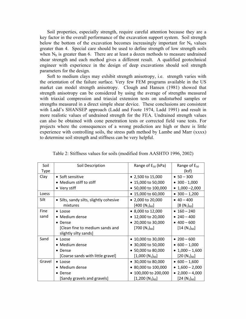
Soil properties, especially strength, require careful attention because they are a key factor in the overall performance of the excavation support system. Soil strength below the bottom of the excavation becomes increasingly important for Nb values greater than 4. Special care should be used to define strength of low strength soils when Nb is greater than 6. There are at least a dozen methods to measure undrained shear strength and each method gives a different result. A qualified geotechnical engineer with experience in the design of deep excavations should soil strength parameters for the design.
Soft to medium clays may exhibit strength anisotropy, i.e. strength varies with the orientation of the failure surface. Very few FEM programs available in the US market can model strength anisotropy. Clough and Hansen (1981) showed that strength anisotropy can be considered by using the average of strengths measured with triaxial compression and triaxial extension tests on undisturbed samples or strengths measured in a direct simple shear device. These conclusions are consistent with Ladd’s SHANSEP approach (Ladd and Foote 1974, Ladd 1991) and result in more realistic values of undrained strength for the FEA. Undrained strength values can also be obtained with cone penetration tests or corrected field vane tests. For projects where the consequences of a wrong prediction are high or there is little experience with controlling soils, the stress path method by Lambe and Marr (xxxx) to determine soil strength and stiffness can be very helpful.
Table 2: Stiffness values for soils (modified from AASHTO 1996, 2002)
Soil Type
Soil Description Range of E50 (kPa) Range of E50 (ksf)
Clay • Soft sensitive • Medium stiff to stiff • Very stiff
• 2,500 to 15,000 • 15,000 to 50,000 • 50,000 to 100,000
• 50 – 300 • 300 - 1,000 • 1,000 –2,000
Loess • 15,000 to 60,000 • 300 – 1,200 Silt
• Silts, sandy silts, slightly cohesive mixtures
• 2,000 to 20,000 [400 (N1)60]
• 40 – 400 [8 (N1)60]
Fine sand
• Loose • Medium dense • Dense
[Clean fine to medium sands and slightly silty sands]
• 8,000 to 12,000 • 12,000 to 20,000 • 20,000 to 30,000
[700 (N1)60]
• 160 – 240 • 240 – 400 • 400 – 600
[14 (N1)60]
Sand
• Loose • Medium dense • Dense
[Coarse sands with little gravel]
• 10,000 to 30,000 • 30,000 to 50,000 • 50,000 to 80,000
[1,000 (N1)60]
• 200 – 600 • 600 – 1,000 • 1,000 – 1,600
[20 (N1)60] Gravel
• Loose • Medium dense • Dense
[Sandy gravels and gravels]
• 30,000 to 80,000 • 80,000 to 100,000 • 100,000 to 200,000
[1,200 (N1)60]
• 600 – 1,600 • 1,600 – 2,000 • 2,000 – 4,000
[24 (N1)60]

Strength values for stiff to very stiff clays and for silts and sands are less critical to the design of excavation support systems with soft clay below the bottom. For most cases, values can be estimated from empirical correlations with SPT tests or cone penetration tests. For a project involving stiff to very stiff clays, silts and sands with no soft cohesive soils, strengths can be estimated from SPT tests or cone penetration tests and local experience.
Finite element methods require values of soil stiffness to make reasonable predictions of displacement; however, soil stiffness is less important than soil strength for values of Nb above 4. Soil stiffness values can be reasonably estimated from the values given in Table 2. For clays, Figure 4 from Duncan and Buchignani (1976) is very useful. K is E50/su. Values from Table 2 and Figure 4 are used as the secant Young’s modulus at a shear stress of half the shear strength, E50. The unloading modulus is typically 3 to 5 times E50. Stiffness data can often be determined from the data used to obtain design strength.
PROPOSED APPROACH TO DISPLACEMENT-BASED DESIGN
The proposed approach is to determine the allowable displacements that minimize
potential damage, establish a trial design and analyze the performance of this design with FEA. Then compare results to the allowable displacements, revise the design and rerun the FEA until the predicted displacements are less than allowable values. The FEA software must have the following capabilities:
• Model non-linear stress-strain behavior for soils, including drained and undrained soil behavior for loading and unloading stress paths.
• Compute factor of safety against global instability. • Model structural components of the wall and support system and their
interaction with the soil. • Compute groundwater pressures and their change with time. • Support removal of elements and correctly adjust nodal forces. • Model the sequence of excavation to closely follow the steps of dewatering,
excavation, support installation and support pre-stressing. Current programs used in the US with these capabilities include PLAXIS, FLAC, SIGMA/W, midasGTS, CRISP, and others.
The following sections describe step-by-step guidelines to establish allowable displacements, then develop a design that deforms less than these values.
Allowable Displacements
Designing to limit movements requires knowledge of how much each structure within the influence zone can deflect without incurring excessive damage. Very few building codes give explicit limits for allowable displacements and these limits are not quantitative. Exceptions are codes for Shanghai, South Korea and some railway agencies in the US. Most of the codes that address this issue put the responsibility on the Builder to avoid damaging all neighboring structures. If not thoroughly familiar with local Code requirements, it is best to consult with a construction attorney familiar with these requirements.
Displacement limits depend on several factors, including the details of the foundation, loads, type of structural framing and exterior shell, and the existing

condition of these elements. Many older buildings may have already undergone significant movement such that floor joists have limited bearing areas. For others, the structural members may have been significantly weakened by rot or insects, or their condition may be totally unknown because they are not visible for inspection. The limit values also depend on the consequences of any significant movement. A building where movement of one inch might cause a collapse and loss of life will require much smaller limits than a building where six inches of wall movement has no consequence to anything or anyone.
Table 1: Allowable Settlement and Tilt of Structures
Type of Movement Limiting Factor Maximum Settlement
Total settlement
Drainage 150 – 300 mm Access 300 – 600 mm Masonry walled structure Framed structures Smokestacks, silos, mats
25 – 50 mm 50 – 100 mm 75 – 300 mm
Tilting/ Differential movement
Tilting of smokestacks, towers 0.004L Stacking of goods, rolling of trucks, or similar 0.01L Machine operation-cotton loom 0.003L Machine operation – turbogenerator 0.0002L Crane rails 0.003L Drainage of floors (0.01 to 0.02)L Framed buildings and reinforced load bearing walls: Structural damage Cracking in walls and partitions Open frames In filled frames Framed buildings
1/150(1) 1/250(2) 1/200(3)
1/300(1) to 1/500(2) 1/300(6)
1/1000(6)
1/300(7) High continuous brick walls (0.0005 to 0.001)L One-story brick mill building, wall cracking (0.001 to 0.002)L Plaster cracking (gypsum) 0.001L Reinforced-concrete building frame (0.0025 to 0.004)L Reinforced-concrete building curtain walls 0.003L Steel frame, continuous 0.002L Simple steel frame 0.005L Unreinforced load bearing walls: Sagging Hogging
1/2500(2)
L/H < 3; 1/3500 – 1/2500(3)
L/H < 5; 1/2000 – 1/1500(3)
1/2500 at L/H = 1(5)
1/1250 at L/H = 5(5)
1/5000 at L/H = 1(5)
1/2500 at L/H = 5(5) Note: Data from Sowers (1962) unless otherwise indicated (1)Skempton &Macdonald (1956), (2)Meyerhof (1956), (3)Polshin & Tolkar (1957), (4)Bjerrum (1963), (5)Burland & Wroth (1975), (6)Meyerhof (1953), (7)Christian & Vanmarke (1974).

There are a number of publications on the allowable settlement and tilt for different types of structures. Table 1 summarizes recommendations from some of these as a useful reference to help set limit values for displacements. Boscardin and Cording (1989) developed a plot relating angular distortion and horizontal strain to building damage. Their principle result is provided in Figure 3.
Figure 3: Angular Distortion and Horizontal Strain Limits
(after Boscardin and Cording, 1989) The recommended approach to establishing displacement limits is as follows:
1. Review project information, local codes, ordinances and requirements from the project’s. Call these values ΔHmax1, ΔVmax1, εH max1 and Δαmax1.
2. If displacements limits are not provided in Step 1, perform a site-specific evaluation. An engineer qualified in structural assessment of constructed facilities should inspect each building and utility within 4H of the ESS to determine its present condition and tolerance for additional settlement, horizontal strain and angular rotation. A larger zone should be evaluated if any significant alteration to the groundwater conditions outside 4H is anticipated. The result of this work should be limits for horizontal displacement of the ESS and settlement, angular distortion and horizontal strain of the ground outside the excavation for each structure. Call these values ΔHmax2, ΔVmax2, εH max2 and Δαmax2.
3. If specific displacement limits are not provided from Steps 1 or 2, use the following method for each structure that might experience damage: a. Determine maximum allowable angular distortion, Δαmax3, from Table 1
depending on building type and condition. Poor condition will lower the allowable values in Table 1.
b. Enter chart by Boscardin and Cording (1989), Figure 3, with allowable angular distortion and allowable damage to determine maximum allowable horizontal strain, εHmax3.
c. Multiply εHmax3 by 3H for an estimate of the maximum allowable horizontal displacement of the wall that limits building damage, ΔHmax3.
d. Estimate maximum allowable ΔVmax3 from values in Table 1 or from which is based on Clough et al (1989).
4. Take the smallest values from Steps 1-3 to obtain ΔHall, ΔVall, εH all and Δαall.

Establish FEA Input
Finite element analysis is a very useful tool for design of ESS, but considerable care must be used by someone familiar with the software, its limitations and with the behavior of soils. The following gives a set of steps that can produce a trial design with 1 or 2 re-runs of the software once the finite element geometric model is correct. 1. Establish the subsurface conditions, including material properties. Especially
important are strength and stiffness of soils below the bottom of the excavation and groundwater conditions before and during excavation. See section “Parameters for FEA” for guidance. Use expected value for each parameter.
2. Layout an ESS that works for constructability, i.e. type of wall, type of supports and horizontal and vertical locations for lateral supports. People with experience in constructability of ESS should participate in this step.
3. Compute FOSBH. If less than 1.5, extra attention should be given to reduce any uncertainty about the shear strength of the soil below the excavation.
4. Use Terzaghi et al (1996) which is reproduced in Figure 5 to estimate lateral support loads per unit length of wall. Note that TPM for soft to medium soils has been revised from original Terzaghi and Peck method with the addition of ΔK.
). Use TPM lateral support loads and allowable axial stress to compute the structural area, As, for each support, including the effect of inclined supports such as rakers or tiebacks.
Figure 5: Apparent Earth Pressure Diagrams from Terzaghi et al (1996)
5. Compute stiffness of each support per unit length of the wall using ks=EsAs/L,
where ks is the stiffness of the support member per unit of length, Es is the modulus of elasticity for the support member, As from Step 4 and L is the length of the support member (half length for struts).
6. Compute moments in wall between each strut level and between lowest strut and the bottom of the excavation assuming hinges at each support location and at the bottom of the excavation. This can be done using M=wl2/8, where M is the maximum moment, w is the average stress acting on the segment of length, l. Take the largest value to size the wall. For cantilevered walls and walls with embedment of more than the average strut spacing, h, the maximum moment will be below the bottom strut and should be computed using other methods such as those given in NAVFAC DM 7.2 (1982).

7. Use the maximum moment to compute required EI of wall so that allowable bending stress is not exceeded. Compute I=M*y/σallowable where y is taken as ½ the thickness of the wall. Select thickness of wall based on required EI and wall type that contractor wants to use. I is moment of inertia of the wall.
8. Use Figure 2 with ΔHall/H and FOSBH to estimate the required system stiffness, (EI/γt* h4
avg). 9. With I from Step 8, compute average vertical support spacing, h. Compare this
spacing with that in Step 2 and adjust the spacing where constructability considerations allow or increase I to achieve the required system stiffness.
10. Use resulting EI per unit length of wall as input stiffness for the wall.
Prepare the FEA Model
1. Establish the finite element model giving consideration to the soil layering, the location of lateral supports, depth of the wall, the depth of each excavation stage, and the locations of any external loads.
2. Input information from above and check that all is correct. 3. Input the construction sequence for the FEA. Include steps to calculate FOS for
the full excavation and for other levels where stability might be a concern.
Do the Finite Element Analysis
1. Make the finite element run. 2. Examine contour plots of stresses, strains and displacements for discrepancies,
anomalies and unusual patterns. If these are present, examine the input data and results for each excavation step to locate the cause of the anomaly. Challenge any result that contradicts engineering judgment. Correct errors and rerun the analysis before proceeding to the next step.
3. Compare FEA forces in the supports to those calculated with TPM and the allowable stresses. The important part of this step is that the total loads are comparable and that any differences are explainable.
4. Compare the maximum moment in the wall to the value computed with TPM and the allowable moment. The FEA value will typically be similar to the value from TPM if the wall embedment is less than h. It may be much larger if the wall embedment exceeds h.
5. Compare maximum horizontal displacement of the wall, maximum vertical displacement of ground surface outside the excavation, horizontal strain at the ground surface outside the excavation and angular rotation of the ground surface to the values established in section “Allowable Displacements.”
Revise the Trial Design 1. Multiply the FEA lateral support loads by 1.3 to account for variability that TPM
indicates. Adjust the size of lateral support members to meet structural design requirements for these loads. Resize the wall dimensions to satisfy structural design requirements using the maximum moment from the FEA analysis.
2. Apply preload of 50% to 100% to supports, if further reduction in the computed displacements is required.
3. If lateral displacement of the wall exceeds ΔHmax by more than a factor of 2, increase the support stiffness by a factor of 5. If FEA maximum settlement

outside the wall is considerably more than the allowable value and more than the FEA maximum horizontal displacement of the wall then consider increasing the embedment of the wall.
4. Repeat the steps under “Do the Finite Element Analysis.” Multiple adjustments and repeats may be required to find the optimal design. A point may be reached where further increases in strut or wall stiffness will not be very effective and the support loads will increase significantly. If the displacements remain larger than the allowable values, the value of h may have to be decreased. These steps do not consider the effects of uncertainties in the soil profile and
properties. The ease-of-use of modern FEA programs make multiple parametric studies practical. The computed deflections, loads, stresses, moments and FOS from these analyses have to be compared to the allowable values and the risk/cost aspects of the workable options.
Structural Design
Following TPM, the axial capacity of the lateral supports computed in the FEA should be increased by 33% to account for individual variability that can occur in any one support. The envelope of maximum values computed with the FEA can be used as the design moments and shear forces for design of the wall.
Some agencies require an evaluation of the removal of any one lateral support element. This can be simulated in a two-dimensional FEA by removing the lateral support one level at a time and examining the effects on the moments and shear in the wall and forces in the lateral supports. In this case, the FEA forces in the adjacent lateral supports need not be increased by 33% for design since this is a check on an extreme load condition.
Temperature changes can greatly increase strut loads in hot conditions and decrease them with possible additional movements in the cold. These need to be considered in the structural design or steps be taken to reduce temperature changes. Freezing of ground behind the all can also create large forces in the lateral support system and wall. This condition cannot be reliably analyzed and should be avoided.
Settlement and bearing capacity failure of the wall base can cause additional movement when lateral supports are inclined or vertical load is added to the wall. The FEA will detect this condition and automatically consider it in the analysis.
DEMONSTRATION OF THE DISPLACEMENT-BASED APPROACH
Figure 6 shows a project where the Owner wants to construct a four-level parking garage. He would be elated with five levels. The site conditions are typical of some locations in the US but have been generalized to avoid any similarity to actual projects. The four-level garage requires excavation to 42.5 ft depth and the five-level garage requires a 52.5 ft deep excavation. Older design methods usually limited excavations in these conditions to two or three levels. An evaluation of nearby structures using the approach described above results in allowable displacement values of ΔHmax < 1 inch; ΔVmax < ¾ inch; Δαmax < 0.001 and Δεmax < 0.001. Below the excavation is a normally consolidated soft clay with shear strength at a depth of 45 feet of 620 psf increasing to 1260 psf at 100 ft deep. It is not clear what shear strength to use to compute FOSBH because the method considers constant shear

strength with depth. FOSBH for the example was computed using the strength at the mid-point of the soil below the bottom of the excavation.
Analyses with PLAXIS using the procedures outlined in this paper gave the results in Table 3. Case 1a is for 42.5 ft deep excavation without preload and Case 1b is with 100% preload. Cases 2a and 2b are for the 52.5 ft deep excavation without and with preload. The preload reduces movements but the values are well above the limit values.
Table 3 summarizes calculations of strut forces and maximum bending moments using Terzaghi et al (1996) for both depths. Also included are the values determined from FEA. Cases 1a, 1b, 2a and 2b are structurally stable but the displacements are much more than the allowable values. The sum of the strut loads computed by PLAXIS are 3 to 26% higher than computed by the TPM method. The loads are considerably higher than the TPM conclusion that actual earth pressures should, on average, be 25% less than loads computed with their method. The maximum moments computed by PLAXIS are considerably higher than those by TPM method, which contradicts the TPM conclusion that generally the actual moments should be less than those computed from the TPM method. These higher forces and moments result from increasing the wall and strut stiffness to reduce deflection, something the TPM method does not take into account.
Another interesting result in Table 3 is the FOS information. From calculations on many different types of facilities, it has been determined that the PLAXIS FOS is equal to or better than other methods because it finds the most critical failure surface of any shape and computes a value equal to or slightly lower than that obtained with limit equilibrium using Spencer’s method. This capability is particularly useful for design of excavations where strength varies with depth in ways that other solutions cannot consider. Figure 7 illustrates the critical surfaces determined by PLAXIS for a case where it reaches to the bottom of the soft soil and another case where it passes through the middle of the soft clay. Note that FOSBH from FEA is similar to that calculated with the basal heave equation using the average undrained strength below the excavation. For Case 3, the PLAXIS FOS is considerably more than the basal heave value because of the added embedment and increased stiffness of the wall that the basal heave method cannot consider.
Several options can be examined with FEA to determine how to reduce movements. Additional runs were made on the hypothetical case to examine strut stiffness, strut spacing, wall stiffness, and wall embedment. The final variation
Figure 6: Hypothetical Project

Table 3: Comparison of PLAXIS Results to Results from Peck Diagrams (forces in kips/ft, moments in kip-ft/ft
that keeps the movement of a building on the surface close to the allowable values for the 42.5 ft deep excavation is to increase wall stiffness 210 times, strut stiffness by 6 to 13 times, embedment of wall from 2.5 ft to 22.5 and use a 100% preload. The results are summarized in Table 3 as Case 3. Similarly for the 52.5 ft deep excavation the wall stiffness was increased 200 times, strut stiffness by 5 to 10 times with 100% preload and embedment all the way to a firm base at 100 ft depth for Case 4. Note that for Case 3, the maximum horizontal displacement exceeds the 1 inch limit but this occurs at the bottom of the stiff, extended wall with no effects on external structures. Maximum settlement, horizontal strain and angular distortion are within the allowable limits set for the hypothetical case.
Figure 7: Shear Strain Contours at Failure for Cases 1b and 2b
There are some other interesting results in Table 3. Very large struts with high preloads and a very stiff wall are required to minimize horizontal displacement and settlement; but, a stable solution is found. Increasing the stiffness of the wall and struts greatly increases the maximum moment in the wall as shown for Cases 3 and 4. It may not be economical to build these solutions but the FEA results show that constructing the excavation to 52.5 ft and meeting the tight displacement limits is possible, even with the soft soil conditions at the bottom of the excavation.
With additional parametric studies other alternatives might be found that would be less expensive to construct. A considerable number of variations were considered to find the results for Cases 3 and 4. The results computed from PLAXIS are plotted onto Figure 3 to compare with Clough et al’s 1989 results. There is general agreement with the values for cases where struts are not preloaded in the FEA. Preloading in general reduces the predicted movements relative to those one would calculate from Figure 3. The good agreement in Figure 3 shows that the PLAXIS
Case Total Strut Load by TPM
Max. M by TPM
FOS by Basal Heave Equation
Pre-load
Total Strut Load by PLAXIS
Max. M by PLAXIS
FOS by PLAXIS
Hmax (in)
Vmax (in)
εHOR
(%) αMAX
1a 108 80.6 1.14 0 125 138 1.10 8.36 4.85 0.97 0.003 1b 108 80.6 1.14 100 136 189 1.10 6.49 3.76 0.82 0.003 2a 189 84.7 0.93 0 195 413 1.03 18.2 10.02 1.5 0.007 2b 189 84.7 0.93 100 214 434 1.03 13.2 7.78 0.95 0.005 3 108 80.6 0.93 100 209 1040 1.77 2.03 0.86 0.10 0.0005 4 189 84.7 N/A 100 220 1670 N/A 0.99 0.54 0.10 0.0003
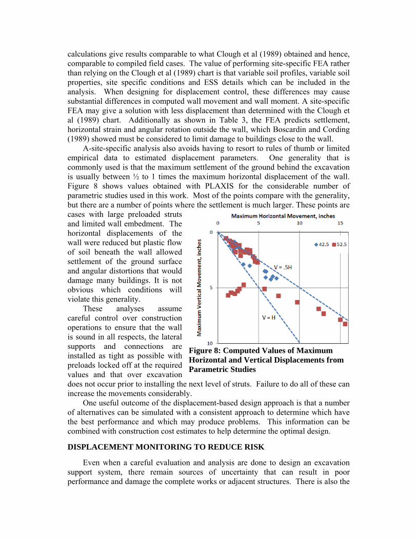
calculations give results comparable to what Clough et al (1989) obtained and hence, comparable to compiled field cases. The value of performing site-specific FEA rather than relying on the Clough et al (1989) chart is that variable soil profiles, variable soil properties, site specific conditions and ESS details which can be included in the analysis. When designing for displacement control, these differences may cause substantial differences in computed wall movement and wall moment. A site-specific FEA may give a solution with less displacement than determined with the Clough et al (1989) chart. Additionally as shown in Table 3, the FEA predicts settlement, horizontal strain and angular rotation outside the wall, which Boscardin and Cording (1989) showed must be considered to limit damage to buildings close to the wall.
A-site-specific analysis also avoids having to resort to rules of thumb or limited empirical data to estimated displacement parameters. One generality that is commonly used is that the maximum settlement of the ground behind the excavation is usually between ½ to 1 times the maximum horizontal displacement of the wall. Figure 8 shows values obtained with PLAXIS for the considerable number of parametric studies used in this work. Most of the points compare with the generality, but there are a number of points where the settlement is much larger. These points are cases with large preloaded struts and limited wall embedment. The horizontal displacements of the wall were reduced but plastic flow of soil beneath the wall allowed settlement of the ground surface and angular distortions that would damage many buildings. It is not obvious which conditions will violate this generality.
These analyses assume careful control over construction operations to ensure that the wall is sound in all respects, the lateral supports and connections are installed as tight as possible with preloads locked off at the required values and that over excavation does not occur prior to installing the next level of struts. Failure to do all of these can increase the movements considerably.
One useful outcome of the displacement-based design approach is that a number of alternatives can be simulated with a consistent approach to determine which have the best performance and which may produce problems. This information can be combined with construction cost estimates to help determine the optimal design.
DISPLACEMENT MONITORING TO REDUCE RISK
Even when a careful evaluation and analysis are done to design an excavation support system, there remain sources of uncertainty that can result in poor performance and damage the complete works or adjacent structures. There is also the
Figure 8: Computed Values of Maximum Horizontal and Vertical Displacements from Parametric Studies

unknown effect of quality of the construction workmanship and attention to detail. Contractors are production oriented people who resist actions that slow them down. Limiting depth of excavation until lateral supports are installed, preloading supports with lock off at design levels, reducing strut spacing and controlling ingress of water and soil particles are steps many contractors resist. These mechanisms can increase lateral wall movements and ground settlements by factors of two or more. Detection of unexpected behavior during the excavation process can only be done with performance monitoring from start to finish. An effective monitoring program must be a part of the design for any excavation where the consequences of larger than expected movements are significant. Marr (2007) discusses benefits of performance monitoring programs that are applicable to deep excavations. CONCLUSIONS
Design of excavations in urban areas is becoming more complex due to
increasing requirements for deeper excavations on poorer sites, tighter limits on allowable displacements for adjacent structures and new methods of construction that extend beyond the experience base used to develop historical design methods. Increasingly, designs are controlled by the need to limit movements and not by the need to avoid collapse. This requires a new approach to designing excavation support systems, one that focuses on controlling movements.
The step-by-step design approach laid out in this paper will result in a design that limits movements, provides adequate factors of safety against soil failure and provides realistic forces and moments to design the structural members. Each site has a unique set of conditions that may violate generalities and rules of thumb used in the past. With tighter restrictions and more demanding situations, site-specific finite element analyses permit more accurate prediction of horizontal deflection of the wall and settlement, angular rotation and horizontal strain outside the wall.
The application of the proposed method to a hypothetical project shows that despite very difficult conditions involving excavation into soft clay, ways can be found that meet strict displacement limits. These involve stiff struts with 100% preloads, stiff walls and significant wall embedment. The solutions may or may not be economically feasible but they show the power of using FEA to provide a consistent and rational method to design excavation support systems that meet specific displacement criteria.
REFERENCES AASHTO (1996) “Standard Specifications for Highway Bridges, 16th Edition.” Washington,
D.C. and 2002 17th Edition. Bjerrum, L. (1963) “Discussion session IV.” Proc, European Conf. on Soil Mech. and
Found. Engr., Wiesbaden, Germany, II, 135-137. Boscardin, M.D. and Cording, E.J. (Jan. 1989) “Building Response to Excavation Induced
Settlement.” ASCE:JGE, Vol. 115, No. 1. Burland, J.B. and Wroth, C.P. (1974) “Settlement of buildings and associated damage.”
Proc Conf. on Settlement of Structures, Pentech Press, London, England.

Clough, G.W., Weber,P.R. and Lamont, J. (1972) “Design and Observation of a Tied-Back Wall,” Proc. Specialty Conf. on Performance of Earth and Earth Supported Structures, Purdue University, pp. 1367-1390.
Clough, G.W. and Hansen, L.A.(1981) “Clay Anisotropy and Braced Wall Behavior.” ASCE:JGED Vol. 107, No. CT7, July 1981, pp. 893-914.
Clough, G.W, Smith, E.M. and Sweeney, B.P.(1989) “Movement Control of Excavation Support Systems by Iterative Design.” Proc. ASCE, Foundation Engineering: Current Principles and Practices, Vol. 2, 1989, pp. 869-884.
Clough, G.W. and O’Rourke, T.D. (1990) “Construction Induced Movements of In-situ Walls.” Proc, ASCE Conf. on Des. And Perf. of Earth Retaining Struct., Geotech. Spec.Publ. No.25, ASCE, New York, 439-470.
Duncan, J.M. and Buchignani, A.L. (1976) “An Engineering Manual for Settlement Studies.” Department of Civil Engineering, University of California, Berkeley.
Goldberg, D.T., Jaworski, W.E. and Gordon, M.D.(1976) “Lateral Support Systems and Underpinning.” Report FHWA-RD-75-128, Vol. 1, FHWA, Washington, D.C. Apr. 1976
Grant, R., J. T. Christian, and E. H. Vanmarcke (1974), "Differential Settlement of Buildings," Jour., Geot. Engr. Div., ASCE, Vol. 100, No. GT9, pp. 973-991.
Hana, A.I. and Clough, G.W.(1981) “Prediction of Movements of Braced Cuts in Clay.” ASCE:JGD, Vol. 107, No. GT6, pp. 759-778.
Jaworski, W.E. (1973) “An Evaluation of the Performance of a Braced Excavation,” Ph.D. Thesis, Massachusetts Institute of Technology.
Ladd, C.C. and Foote, R. (1974) “A new design procedure for stability of soft clays.” ASCE:JGED, Vol. 100, No. GT7. pp. 763-786.
Ladd C.C. (1991) “Stability Evaluation During Staged Construction.” The Twenty-Second Karl Terzaghi Lecture, ASCE:JGE Vol. 117, No. 4, 540-615.
Lambe, T.W. and Marr, W.A. (1979) "Stress Path Method-Second Edition", Proc. ASCE:JGED, Vol. 105, No. GT6, pp. 727-738
Marr, W. A (2007) “Why Monitor Performance?” ASCE: GSP 117. Keynote paper presented to 7th International Symposium on Field Measurements in GeoMechanics, Boston.
Meyerhoff, G.G. (1953) “The Bearing Capacity of Foundationa under Eccentric and Inclined Loads,” Proc. 3rd ICSM. Zurich, 1, pp. 440-450
Meyerhoff, G.G. (1956) “ xxx anand NAVFAC (1982) Design Manual DM-7, Department of Navy, Washington, D.C. Peck, R. B. (1969) “Deep Excavations and Tunneling in Soft Ground.” State-of-the-Art-
Report, 7th ICSMFE, Mexico City, State-of-the-Art Volume, pp. 225-290. Polshin, D.E. and Tolkar, R.A. (1957) “Maximum Allowable Nonuniform Settlement of
Structures, Proc. 4th ICSMFE, Vol.I, p. 402. Poulos H.G. (2000) “Foundation Settlement Analysis – Practice Versus Research.” 8th
Spencer J. Buchanan Lecture, Texas A&M University, College Station, Texas Skempton, A.W. (1951) “The bearing capacity of clays,” Prod. British Bldg, Research
Congress, pp. 180-189. Skempton, A.W. and MacDonald, D.H. (1956) “The allowable settlement of buildings.”
Proc. Inst. of Civ. Engrs., Part III, 5, 727-784. Sowers, G.F. (1962) Shallow Foundations, Foundation Engineering, G.A. Leonards (ed.)
McGraw-Hill Book Co., New York, NY, pp. 525-632. Terzaghi, K. (1943) Theoretical Soil Mechanics, John Wiley & Sons, Inc., New York, NY. Terzaghi, K. Peck, R.B. and Mesri, G. (1996) Soil Mechanics in Engineering Practice: Third
Edition. John Wiley & Sons, Inc.