1-1 accessory - · pdf filethank you for purchasing koso rs dyno digital lcm meter the meter...
TRANSCRIPT
INTRODUCTION
Thank you for purchasing KOSO RS DYNO digital LCM meter the meter is displayed by lcm with led back light, before operating, please read the instruction carefully and follow it to install the meter.
NOTICE1.The lcd meter is apply for DC 12V.2.For installation, please follow the steps described in manual. Any damage caused by wrong installation shall be imputed to the users.3.Don't break or modify the wire terminal. To avoid the short circuit, please don't pull the wire when installing.4.Do not disassemble or change any parts excluding the manual description.5.The interior examination or maintenance should be executed by our professionals.
WARNING!CAUTION!
You could get the installation details from the information behind the mark.
Some processes must be followed to avoid the affection caused by wrong installation.
Some processes must be followed to avoid damages to yourself or the public.
Some processes must be followed to avoid the damage to the vehicle.
MARK MEANING:
ContentAccessory1-1
Option accessory1-2
2-1
Installation instructions2-2
Wiring installation instructions
3-1 Basic function instruction
3-2 Standard screen function instruction
3-3 The button function instruction
3-4 The screen switch instruction
3-5 Main screen function switch instruction
3-6 Digital screen function switch instruction
3-7 The setting screen instruction
4 Function, setting instruction
4-1 Speed unit setting
4-2 Cycle/ piston setting
4-3 The temperature unit setting
4-4 Speeding warning light setting
1-14-5 Over RPM warning light setting
4-6 Over temperature (Water temperature)
warning light 1 setting
4-7 Over temperature (Oil temperature)
warning light 2 setting
4-8 Tire size adjustment/ sensor point setting
instruction
4-9 The clock setting instruction
4-10 Fuel sensor impedance & insufficient fuel
warning setting instruction
4-11 The target speed timer / target distance
timer setting
5-1 Target speed timer test
5-2 Target distance timer test
5-3 The top speed test
6 Trouble shooting
Guarantee & notice of products7
Guaranty8
2
5
8
1
4
7
10
3
6
9
11 12
TEM
P 2 TE
MP 1
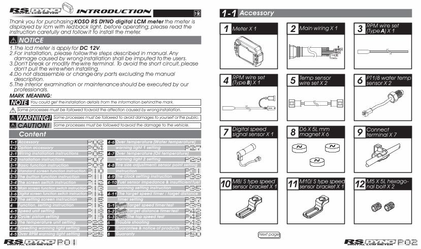
Meter X 1 Main wiring X 1
PT1/8 water temp sensor X 2
Connect terminal X 7
D6 X 5L mm magnet X 6
Digital speed signal sensor X 1
M8/ S type speed sensor bracket X 1
M5 X 5L hexago-nal bolt X 2
RPM wire set(Type A) X 1
RPM wire set(Type B) X 1
M10/ S type speed sensor bracket X 1
Temp sensor wire set X 2
Accessory1-1
Next page

13 14 15
16
19
17 18
Please contact us if the items you open are not the same, with the above-listed ones.
Manual
2.5 mm spanner X 1
4 mm spanner X 1
M5 gasket X 2M5 X 12L screw X 2
M5 X 18L screw X 2
Meter bracket X 1 set
Accessory1-1
2
5
8
1
4
7
3
6
Option accessory1-2
Some of the option accessories may not be sold. For the details, please contact the local distributor.
Active speed sensor
Disc magnet screw
5/16-18 X 22.1LM5 X P0.8 X 12L
M6 X P1.0 X 12.6LM6 X P1.0 X 19.7L
M6 X P1.0 X 24LM8 X P1.25 X 22.5L M8 X P1.25 X 27.5L
M8 X P1.25 X 29L M10 X P1.25 X 28.3L
M14M16.M18
M22.M26 mm
M12 X P1.5 X 15L M14 X P1.25 X 15L
M14 X P1.5 X 15LM16 X P1.5 X 15LM18 X P1.5 X 15LM20 X P1.0 X 15LM20 X P1.5 X 15L
Oil temp sensor adapter
Water temp sensor adapter
M10 X P1.0 M12 X P1.5
M14 X P1.25M14 X P1.5
M16 X P1.5 / M18 X P1.5
M10.M14 mm
Temp sensorCylinder head temp sensor
Meter bracketL type speed sensor bracket

2-1
TEM
P 2
TEM
P 1
Meter (Accessory 1)
The ignition coil positive electrode Spark plug wire
RPM wire set-type A (Accessory 3)
Temp sensor wire (Accessory 5) PT1/8 (Accessory 6) Please install the temp sensor to the position you want to measure.
Black / Ground wire connect to the vehicle body or the engine (It must be a good ground)
Red / "+"Wire connect key on DC 12V main power switch
Magnet (Accessory 8)
Digital speed signal sensor (Accessory 7)Brown / RPM
RPM wire set-type B (Accessory 4)
RPM wire set-type A (Accessory 3)
Pick-upIgnition control box
Wiring installation instructions
Main wiring (Accessory 2)
If you don't connect the fuel wiring, the fuel gauge will not display.
The north (N) side of magnet must face to the sensor when installing.
We provide 2 ways to get the RPM signal-sensor A & sensor B. If there are interruptions, you could change the sensor wiring to get better signal.
CAUTION! Just wind the RPM wire(A) onto the spark plug wire. Do not connect them! We also suggest you to replace the "R" type spark plug in the mean time to get better signal. FFor the model more than one piston, please catch the signal from the first cylinder coil wire.or the model with more than one piston, please just connect the RPM sensor wiring to one of the ignition coil positive electrodes.Please make sure that the ignition coil positive electrode before connecting the RPM sensor wiring! Wrong installation will cause the meter broken!
When connecting the power wiring, please follow the instruction. If you connect the red & brown wiring in parallel will cause the meter work improperly.
Yellow / fuel (-)
Gray / oil light (+12V/-)
Green / white- neutral (-)
Orange / L turn signal (+12V)
Blue / R turn signal (+12V)
YAMAHAHONDASUZUKI
SYM
Main switch wiring reference:
"+" Color "-" ColorBrownBrown
Black
Green
The color listed above may differ depending on the model.
BlackBlackBlack Green
YAMAHA HONDA SUZUKI SYMFuel indicator wiring reference:
Yellow/white Yellow/white Yellow/white
The fuel sensor is electronic type, please don't parallel connection with the original, otherwise the fuel gauge won't display.The wrong installation of the fuel wiring may cause the meter broken.
Green
Water temperature
Oil temperature

2-2
1.
2.
2.
3.5.
4.6.
7.
1.M5 X 12L screw X 22.Meter bracket for handle bar3.Fix the bracket on handle bar (7/8 inch)4.M5 X 18L screw X 25.M5 washer X 2
6.Meter fixed board7.Fix the meter on the board (6) with the screw (5)8.Fix the meter and the bracket together
Please adjust the meter to the best visible angle before tightening the screw
MOTO/SCOOTER
Use the bind & the non-slip rubber to fix bracket to the front of the shock and adjust the proper height and angle.
Speed sensor installation find a proper hole to put the sensor in and fix it by hexagonal bolt.
Please keep the distance between sensor and magnet in 8 mm to avoid bad signal.
L type speed sensor bracket instruction
About the setting, please refer to 4-8 tire size adjustment/ sensor point setting instruction
Installation instructions
When installing, please follow the process
1
23
ATV
Magnet (for speed signal)Magnet (for speed signal)
Speed sensorSpeed sensor
S type sensor bracketS type sensor bracket
S type speed sensor bracket instruction
1
2
3
Insert the signal magnet. (You need to dig a hole by yourself).
Install the s-type sensor bracket, you could adjust the proper distance and angle to fit different model.
After installing the sensor, please adjust the distance between sensor and magnet . Please keep the distance in 8 mm.
MOTO/SCOOTER
SPEEDSENSORSPEED
SENSORMAGNETMAGNETBELOW
mm8BELOW8mm
S type speed sensor bracket instruction
P.S.P.S.The more magnet sensor points are, the less the display interval is. When installing the magnet, please put the magnet with N-mark side face the outside and put them averagely to avoid wrong signal.EX. 1: If your disk has 3 screws, you could install 1 or 3 magnets to catch the speed.EX. 2: If your disk has 4 screws, you could install 1 2 or 4 magnets to catch the speed.EX. 3: If your disk has 5 screws, you could install 1 or 5 magnets to catch the speed.EX. 4: If your disk has 6 screws, you could install 1 2 3 or 6 magnets to catch the speed.After finishing the magnet installation and sensor point setting, please move your tire to test the speedometer work or not.
EX. 1 EX. 2EX. 3 EX. 4
Put the magnet into the brake disc screw hole.
Install the s type sensor bracket.
Install the speed sensor on the bracket.
Adjust the sensor bracket position to make sure that the sensor could face the magnet to prevent bad speed signal or no signal!
Adjust the distance between sensor and magnet. We suggest you to make sure the distance is under 8mm for catching good speed signal.
Put the magnet into the brake disc screw hole.
SPEEDSENSORSPEED
SENSORMAGNETMAGNETBELOW
mm8BELOW8mm

En
te
rE
xit
Do
wn
3-1
138 mm 49 mm
81
mm3
7 m
m
Clock24 H.
Indicator lightsFrom left to right: over RPM, speeding, over temperature (water) warning light 1, over-temperature (oil) warning light 2, natural, flash light, and oil lights.
Voltage indicatorDisplay range: DC 9.5~24.0 V.Display unit: DC 0.1 V.
Tachometer Display range: 0~9,000/ 18,000 RPM.Display unit: 500 RPM.Over-RPM warning light Setting range: 3,000~22,000 RPM. Setting unit: 100 RPM.
Odo meterDisplay range: 0~99999.9 km/h, and then restart from 0. Display unit: km/h or MPH can be changed.
Trip meter Display range: 0~999.9 km/h, and then restart from 0, manually or automatically.Display unit: km/h or MPH can be changed.
Basic function instruction
Water/ oil indicatoro
Display range: 0~150 C (32~o
302 F) 10 levels, each level o o
represents 15 C (27 F).o o
Display unit: C/ F for alternative.
Over temperature warning light o
Setting range: 50~150 C (122~o
302 F). o o
Setting unit: 1 C ( F). Fuel indicatorDisplay unit: 10 levels, each level represents 10 %.Fuel indicator: 100 Ù, 510 Ù, no display.
Fuel warning Setting range: 10~50 %. Setting unit: 10 %.
SpeedometerDisplay range: 0~360 km/h (0~223 MPH). Display unit: km/h or MPH can be changed.
Speeding warning light Setting range: 30~180 km/h (19~112 MPH).Setting unit: 1 km/h (MPH).
En
te
rE
xit
Do
wn
3-2 Standard screen function instruction
Indicator lightsFrom left to right: over RPM, speeding, over temperature (water) warning light 1, over-temperature (oil) warning light 2, natural, flash light, and oil lights.
Voltage indicatorDisplay range: DC 9.5~24.0 V.Display unit: DC 0.1 V.
Water/ oil indicatoro oDisplay range: 0~150 C (32~302 F)
o oDisplay unit: C/ F for alternative.
Over temperature warning light Setting range: 50~
o o150 C (122~302 F).o oSetting unit : 1 C ( F).
Fuel indicatorDisplay unit: 10 levels, each level represents 10 %.Fuel indicator: 100 Ù, 510 Ù, no display.
Fuel warning Setting range: 10~50 %. Setting unit: 10 %.
Tachometer Display range: 0~22,000 RPM.Display unit: 100 RPM.
Over-RPM warning light Setting range: 3,000~22,000 RPM. Setting unit: 100 RPM.
SpeedometerDisplay range: 0~360 km/h (0~223 MPH). Display unit: km/h or MPH can be changed.
Speeding warning light Setting range: 30~180 km/h (19~112 MPH).Setting unit: 1 km/h (MPH).
Odo meterDisplay range: 0~99999.9 km/h, and then restart from 0. Display unit: km/h or MPH can be changed.
Trip meter Display range: 0~999.9 km/h, and then restart from 0, manually or automatically.Display unit: km/h or MPH can be changed.
Clock24 H.

3-3
In main/digital screen, press button to select the function display between odometer, trip meter and clock. (Please refer to 3-4 & 3-5)In setting screen, press button to select the screen you want to make the setting. (Please refer to 3-6)In function setting screen, press button to select the units and decrease the setting value (Like the figure below) , press or hold down to decrease the setting value .
In main/digital screen, press button to select the function display between water temperature, oil temperature, and the fuel . (Please refer to 3-4 & 3-5)In setting screen, press button to select the screen you want to make the setting. (Please refer to 3-6)In function setting screen, press button to select the units and increase the setting value (like the figure below) , press or hold down to increase the setting value automatically.
BUTTON
BUTTON
BUTTON
BUTTON
BUTTON X 3 SECONDS
The button function instruction
Press button to switch between main screen, digital screen, and the power test screen.
Press button one time to enter the setting screen or to back to the main screen from any screens.
In the screen with trip meter, hold down button for 3 seconds to reset the trip meter.
3-4
In digital screen: Press button to enter the Power test
screen.
In setting screen: Press button to get back to the main screen.
In main screen: Press button to enter the setting screen.
In main screen: Press button to enter digital screen.
The screen switch instruction
In power test screen: Press button to back to the main screen.
Press button to return to the main screen in any screen.

3-5 Main screen function switch instruction
In main screen: Press button to switch the oil temperature to the fuel indicator.EX. Now the left-side screen displays the oil temperature.
In main screen: Press button to switch the fuel indicator to the water temperature.EX. Now the left-side screen displays the Fuel.
In main screen: Press button to switch the water temperature to the oil temperature.EX. Now the left-side screen displays the oil temperature.
In main screen: Press button to switch the trip meter to clock. EX. Now the screen displays the trip meter.
In main screen: Press button to switch to the odometer. EX. Now the screen displays the clock.
In main screen: Press button to switch the odometer to trip meter.EX. Now the screen displays the odometer.
3-6 Digital screen function switch instruction
In digital screen: Press button to switch the oil temperature to the fuel indicator.
oEX. Now oil temperature is 28.5 C.
In digital screen: Press button to switch the fuel indicator to the water temperature.EX. Now fuel indicator is full.
In digital screen: Press button to switch the water temperature to the oil temperature. EX. Now water temperature is
o28.5 C.
In digital screen: Press button to switch the odometer to trip meter. EX. Now the odometer is 0 km.
In digital screen: Press button to switch the trip meter to clock. EX. Now the trip meter is 0 km.
In digital screen: Press button to switch to the odometer. EX. Now the time is 0:00.

-2-2
-3-3
-4-4
-5-5
-8-8
-9-9
-10-10
+1
+10+2
+9
+8
+3
+4
+7
+6
+5
3-7
When entering the setting screen, if you don't press any buttons after 30 seconds, it will return to the main screen automatically.
Press button to select the screen you want , in order of S-1, S-2 ,S-3.Press button to select the screen you want, in order of S-11, S-10, S-9, S-8.
The setting screen instruction
-1-1
-6-6-7-7
-11-11 +11
Display range: 0~360 km/h (0~223 MPH)Speedometer
Setting range: 30~180 km/h (19~112 MPH)
Setting unit: 1 mm Sensitive point: 1~6
Needle tachometer
Digital tachometer
Temperature
Level water indicator
Level oil indicator
Digital water indicator
Digital oil indicator
o oDisplay range: 0~150 C (32~302 F)
o oDisplay range: 0~150 C (32~302 F)
o oDisplay range: 0~150 C (32~302 F), 10 levels
o oDisplay range: 0~150 C (32~302 F), 10 levels
Setting range: 3,000~22,000 RPM
Display range: 0~9,000/ 18,000 RPM
Display range: 0~22,000 RPM
Tire circumference Setting range: 1,000~2,500 mm
Speeding warning light
Odometer
Trip meter
0~99999.9 km, reset automatically after 99999.9 km.
0~999.9 km, reset automatically after 999.9 km
Setting unit: 1 km/h (MPH)
Display internal
Display internal
<0.5 second
<0.5 second
Over RPM warning light
Stroke / piston setting 2 Stroke: 1, 2, 3, 4 pistons
4 Stroke: 1, 2, 3, 4, 5, 6, 8, 10, 12 pistons
Display unit: km/h & MPH for alternative
Display unit: 500 RPM
Display unit: 100 RPM
Setting unit: 100 RPM
o oDisplay unit: C & F for alternative
o oDisplay unit: Each level represents 15 C (27 F)
o oDisplay unit: Each level represents 15 C (27 F)
o oDisplay unit: 0.1 C ( F)
o oDisplay unit: 0.1 C ( F)
4 Function, setting instruction
Next page

Design and Specifications are subject to change without notice!
4 Function, setting instruction 4-1Press button once (Or the button 11 times) to select the speed unit setting screen.
If you just want to check the setting, press button to return to the main screen.
Press button to enter the setting screen. EX. Now the original setting is km/h.
Press button or to select the speed unit.
km/h and MPH is alternative.
Now the km/h is flashing!
Press button to return to the main screen. EX. The setting is changed from km/h to MPH.
Press button or to select the other setting screens.
Speed unit setting
If you just want to make the setting, press button to back to the main screen.
Product weight
Volt meter
Usage voltage
Install voltage
Operating temperature range
Product model
Product size
Indicator light Neutral-green, flash-yellow, oil-red
DC 12V
DC 40Vo
-10~+60 C
JIS D 0203 S2
126 X 81 X 49 mm
Around 200 g
Clock
Fuel indicator
Fuel warning
24 H
Display range: 10 levels
Display range: DC 9.5~24.0 V
Over temperature warning
(water & oil) light o oSetting unit: 1 C ( F)
Setting unit: 10 %
Display unit: Each level represents 10 %
Display unit: DC 0.1V
Display internal <0.5 second
Setting range: 30~360 km/h (20~220 MPH)Target speed timer
Top speed timer
Target distance timer Setting range: 50~1,000 m (1/32~20/32 mile)
Setting unit: 50 m (1/32 mile)
The record including,
Setting unit: 5 km/h (MPH)
1.Speed 0~360 km/h (0~223 MPH)
2.Distance 0~999 m (0~3280 feet)
3.Timer 0~9.59.9 second.
o oSetting range: 50~150 C (122~302 F)
Setting range: 10~50 %
Setting range: 100 Ù, 510 Ù, no display
Display internal <0.5 second

4-2
Next page
Press button 2 times (Or the button 10 times) to select the strokes/pistons setting screen.
CAUTION!
Press button to enter strokes/pistons setting screen. EX. Now the setting is 2-stroke with one single piston.
Press button or to select the stroke.There are 4-stroke and 2-stroke .
Now the 2 is flashing!
Press button to enter pistons setting screen. EX. The setting is changed from 2-Stroke to 4-stroke.
Cycle/ piston setting
Make sure the correct strokes and pistons before setting.Make sure the input is correct, or the RPM output will be incorrect.We define the engine with the ignition system ignites every 360 degree as 2-stroke and the engine with the ignition system ignites every 720 degree as 4-stroke.Some 4-stroke bikes with one single piston are igniting every 360 degree once, so the setting should be the same as the bike with 2-stroke and one piston engine.
If you just want to check the setting, press button to return to the main screen.
Press button or to select the number you want to input.
2-stroke pistons are 1,2,3,4.4-stroke pistons are 1,2,3,4,5,6,8,10,12.
Now the 1 is flashing!
Press button to enter the signal impulse setting.EX. The piston setting is changed from 1 P (Piston) to 4 P (Pistons).
Press button to enter the digital needle tachometer range settingEX. The input signal is changed from low to hight.
Press button or to choose the signal impulse you want to set.
Now the signal impulse setting is flashing!
If the tachometer can't detect the signal (No RPM is displayed on the screen), you could choose another setting and check it again.
The signal impulse setting range is between hight (The positive signal) & low (The negative signal)
Next page

4-2Press button or to choose the range you need.
Now the 9000 is flashing!
Press button to return to strokes/ pistons setting screen. EX. Now the digital needle tachometer range is changed from 9,000 RPM to 18,000 RPM.
Press button or to select the other setting screens.
Cycle/ piston setting
The ranges for selection are 9,000 RPM and 18,000 RPM.
If you just want to make the setting, press button to back to the main screen.
4-3
Press button or to select the other setting screens.
Press button 3 times (Or the button 9 times) to select the temperature unit setting screen.
Press button to enter the setting screen. oEX. Now the setting unit is C.
o oThere are C and F for alternatives.
Press button or to select the temperature unit.
oNow the c is flashing!
Press button to return to temperature unit setting screen.
o oEX. The unit setting is changed from C to F.
The temperature unit setting
If you just want to check the setting, press button to return to the main screen.
If you just want to make the setting, press button to back to the main screen.

4-4
NEXT PAGE
Press button or to select the other setting screens.
Press button 4 times (Or the button 8 times) to select the speeding warning light setting screen.
The speeding warning light is set to be 60 km/h, the red light flashes when speeding. (Like fig. Right)
P.S.P.S.
Press button to enter the speeding warning light setting screen. EX. Now the setting is 30 km/h.
Now the 30 is flashing!
Press button or to select the number you want to input.
The setting range: 30~180 km/h (19~112 MPH). Setting unit: 1 km/h (MPH).
Press button to return to speeding warning light setting screen. EX. The setting is changed from 30 km/h to 60 km/h.
Speeding warning light setting
If you just want to check the setting, press button to return to the main screen.
Next page
En
te
rE
xit
Do
wn
En
te
rE
xit
Do
wn
If you just want to make the setting, press button to back to the main screen.

En
te
rE
xit
Do
wn
En
te
rE
xit
Do
wn
4-5Press button 5 times (Or the button 7 times) to select the over RPM warning light setting screen.
The over RPM warning light will light when the RPM reaches your setting. (The red light) The yellow light will light to warn you 500 RPM before your setting.
P.S.P.S.
Press button to enter the over RPMwarning light setting screen. EX. Now the setting is 10,000 RPM.
Now the 100 is flashing!
Press button to return to over RPM warning light setting screen. EX. The setting is changed from 10,000 RPM to 12,000 RPM.
Over RPM warning light setting
If you just want to check the setting, press button to return to the main screen.
Press button or to select the number you want to input.
NEXT PAGENext page
Press button or to select the other setting screens.
The setting range: 3,000~22,000 RPM. Setting unit: 100 RPM.
If you just want to make the setting, press button to back to the main screen.

En
te
rE
xit
Do
wn
En
te
rE
xit
Do
wn
4-6
P.S.P.S.If the warning light is set
oto be 90 C, the red light will flash when the oil temperature is over your setting. (Like fig. right)
Press button 6 times (Or the button 6 times) to select the over temperature warning light 1 setting screen.
Press button to enter the over temperature warning light 2 setting screen.
oEX. Now the setting is 100 C.
oThe setting range: 50~150 C (122~302o o oF). Setting unit: 1 C ( F).
Now the 100 is flashing!
Press button to return to over temperature warning light 1 setting screen.
o oEX. The setting is changed from 100 C to 90 C.
Press button or to select the other setting screens.
If you just want to check the setting, press button to return to the main screen.
Press button or to select the number you want to input.
NEXT PAGENext page
Over temperature (Water temperature) warning light 1 setting
If you just want to make the setting, press button to back to the main screen.

4-7 Over temperature (Oil temperature) warning light 2 setting
Press button 7 times (Or the button 5 times) to select the over temperature warning light 2 setting screen.
P.S.P.S.
Press button to enter the over temperature warning light 2 setting screen.
oEX. Now the setting is 100 C.
Press button or to select the number you want to input.
Press button to return to over temperature warning light 2 setting screen.
o oEX. The setting is changed from 100 C to 90 C.
Press button or to select the other setting screens.
If the warning light is set oto be 90 C, the red light
will flash when the oil temperature is over your setting. (Like fig. right)
If you just want to check the setting, press button to return to the main screen.
oThe setting range: 50~150 C (122~302o o oF). Setting unit: 1 C ( F).
Now the 100 is flashing!
NEXT PAGENext page
En
te
rE
xit
Do
wn
En
te
rE
xit
Do
wn
If you just want to make the setting, press button to back to the main screen.

4-8
130cm
Press button to enter the sensor point setting screen. EX. Now the circumference is changed from 1,250 mm to 1,300 mm.
Now the 1 is flashing!
Press button to return to the tire size adjustment/ sensor point setting screen. EX. Now the sensor point setting is changed from 1 to 6.
Press button 8 times (Or the button 4 times) to select the tire size adjustment/ sensor point setting screen.
CAUTION!Please measure the circumference of the tire (Please measure the tire
which you will put the magnets on) before setting and make sure the numbers of the magnets (Installed to the breaking rotor or the screws on the sprocket.)
Please make sure all the input value is correct, or the output data will be affected.
Press button to enter the setting screen. EX. The circumference setting is 1,250 mm and the sensor point is 1.
P.S.P.S.You could define the valve as the starting point and the terminal point to measure the wheel circumference with a measuring tape.
The setting range: 1,000~2,500 mm. Setting unit: 1 mm.
Now the 1250 is flashing!
Tire size adjustment/ sensor point setting instruction
If you just want to check the setting, press button to return to the main screen.
NEXT PAGENext page
Press button or to select the number you want to input.
Press button or to select the number you want to input.
The sensor point setting range is from 1 to 6.
Press button or to select the other setting screens.
If you just want to make the setting, press button to back to the main screen.

4-9 The clock setting instruction
Press button to return to the clock setting instruction screen. EX. The minute is changed from 0 to 1.
Now the 00 is flashing!
Press button 9 times (Or the button 3 times) to select the clock setting instruction setting screen.
Press button to enter the clock setting instruction screen. EX. Now the time is 0:00.
The time range: 0~24 hours.
Now the 0 is flashing!
Press button to enter the minutes setting screen. EX. The hour is changed from 0 to 13.
If you just want to check the setting, press button to return to the main screen.
Press button or to select the number you want to input.
NEXT PAGENext page
Press button or to select the number you want to input.
Press button or to select the other setting screens.
If you just want to make the setting, press button to back to the main screen.

4-10
Now the 30% is flashing!
The setting range: 10~50 % .Setting unit: 10 %.
Press button to return to the previous fuel sensor impedance setting screen.EX. Now the setting is changed from 30 % to 20 %.
Press button to enter the insufficient fuel warning setting screen. EX. Now 100 Ù is changed to 510 Ù.
Fuel sensor impedance & insufficient fuel warning setting instruction
Press button 10 times (Or the button 2 times) to select the fuel impedance & insufficient fuel warning setting screen.
Press button to enter the fuel impedance & insufficient fuel warning setting screen.EX. Now the fuel sensor impedance setting is100 Ù and the insufficient fuel warning is 30 %.
P.S.P.S.Usually the fuel sensor impedance setting is 100 Ù for YAMAHA models, and 510 Ù for the HONDA models, but sometimes it will differ depending on the model.The insufficient fuel warning setting: if the fuel is less than the value you set, it will flash. (Like fig. right)
Fuel sensor impedance setting range: 100 Ù, 510 Ù and no display.
Now the 100 Ù is flashing!
If you just want to check the setting, press button to return to the main screen.
Press button or to select the number you want to input.
NEXT PAGENext page
Press button or to select the number you want to input.
Press button or to select the other setting screens.
En
te
rE
xit
Do
wn
If you just want to make the setting, press button to back to the main screen.
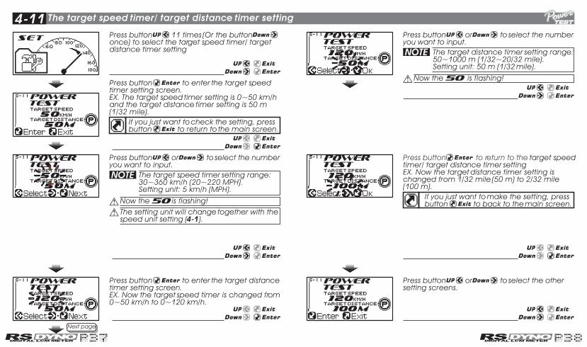
4-11Press button 11 times (Or the button once) to select the target speed timer/ target distance timer setting
The target speed timer/ target distance timer setting
NEXT PAGENext page
Press button to enter the target speed timer setting screen.EX. The target speed timer setting is 0~50 km/h and the target distance timer setting is 50 m (1/32 mile).
If you just want to check the setting, press button to return to the main screen.
Press button or to select the other setting screens.
Now the 50 is flashing!
Press button or to select the number you want to input.
The setting unit will change together with the speed unit setting (4-1).
The target speed timer setting range: 30~360 km/h (20~220 MPH). Setting unit: 5 km/h (MPH).
Press button to enter the target distance timer setting screen.EX. Now the target speed timer is changed from 0~50 km/h to 0~120 km/h.
Now the 50 is flashing!
Press button or to select the number you want to input.
The target distance timer setting range: 50~1000 m (1/32~20/32 mile). Setting unit: 50 m (1/32 mile).
Press button to return to the target speed
timer/ target distance timer settingEX. Now the target distance timer setting is changed from 1/32 mile (50 m) to 2/32 mile (100 m).
If you just want to make the setting, press button to back to the main screen.

5-1 Target speed timer test
The
re
co
rd d
isp
lay s
cre
en
En
ter
the
te
stin
g s
cre
en
if
no
re
co
rd
En
ter
the
te
stin
g s
cre
en
NEXT PAGENext page Next page
During the test.
WARNING!Please use this function at racetrack to avoid traffic accidents.
Please start the test when the bike stops.
If you have the power test record, it will display the record first. You must clear the record before starting a new test.
When the bike moves, the timer will start automatically.
About the power test setting, please check 4-11.
When you reach the target speed you set (0~120 km/h), the timer will stop counting (19.1 second).EX. The dotted line means the previous record, and the true line means the new record. For example, the previous record on the left side curve means the time to reach 120 km/h is 19.2 seconds, and the distance you need is 640 meter. And the new record is 19.1 seconds, and the distance is 639 meter.
0 km/h 3 km/h 120 km/h
In the power test screen, press once (Or the button 3 times.) to enter the target speed timer test screen.
Press button to enter the test standby screen.EX. The target speed timer test setting is 0~120 km/h, the time to reach the speed is 19.2 seconds, and the distance you need to reach the speed is 640 meter.
If you just want to check the record, press button to back to the main screen.
Now the target speed timer is flashing!
The timer and trip meter will start to count automatically when your bike moves. When you reach the target speed you set, the timer and trip meter will stop counting automatically.
Speed upP.S.P.S.
If the speed you set is too low (For example 30~60 km/h), the curve will disconnect because the sampling is not enough.

5-1 Target speed timer test
0 km/h 3 km/h
To stop the timer during the test: 1.Press button , the timer will stop right away and then enter the record screen.2.Press any button to enter the record screen.3.Press button to save the record and enter the record screen or press button to delete the record and enter the previous record screen.4.Press button to enter the target speed timer test? standby screen.
Press button to save the record and then enter the new record screen.
Press button to delete the record and back to the previous record screen.
When you save the new record, the previous record will be replaced.
The record screen.
If you already finished the test, press button to back to the main screen.
If you want to make another test, press button to enter the test standby screen.
Speed up Testfailure
P.S.P.S.
5-2
The
re
co
rd d
isp
lay s
cre
en
En
ter
the
te
stin
g s
cre
en
if
no
re
co
rd
En
ter
the
te
stin
g s
cre
en
NEXT PAGENext page
WARNING!Please use this function at racetrack to avoid traffic accidents.
Please start the test when the bike stops.
If you have the power test record, it will display the record first. You must clear the record before starting a new test.
When the bike moves, the timer will start automatically.
About the power test setting, please check 4-11.
Target distance timer test
In the power test screen, press 2 times (Or the button 2 times.) to enter the Target distance timer test screen.
Press button to enter the test standby screen. EX. The target distance timer test setting is 100 meters the time to reach the distance is 10.2 seconds, and the top speed you reach during the test is 63 km/h.
(2/32 mile)
If you just want to check the record, press button to back to the main screen.
Now the target distance timer is flashing!

5-2
Next page
During the test.
Target distance timer test
When you reach the target distance you set , the timer will stop counting
(10.2 second).EX. The dotted line means the previous record, and the true line means the new record. For example, the previous record on the left side curve means the time to reach 100 km/h is 10.2 seconds, and the top speed you reach is 63 km/h. And the new record is 10.1 seconds, and the top speed you reach is 64 km/h. Press any button to enter the record screen.
(100 m . 2/32 mile)
0km/h 3 km/h 63 km/h
If the distance you set is short (for example 50 or 100 meters), the curve will disconnect because the sampling is not enough.
Speed upP.S.P.S.The timer and trip meter will start to count automatically when your bike moves. When you reach the target distance you set, the speedometer and timer will stop counting automatically.
0 km/h 0 km/h3 km/h
To stop the timer during the test: 1.Press button , the timer will stop right away and then enter the record screen. 2.Press any button to enter the record screen.3.Press button to save the record and enter the record screen or press button to delete the record and enter the previous record screen.4.Press button to enter the target distance timer test? standby screen.
Press button to save the record and then enter the new record screen.
Press button to delete the record and back to the previous record screen.
When you save the new record, the previous record will be replaced.
The record screen.
If you already finished the test, press button to back to the main screen.
If you want to make another test, press button to enter the test standby screen.
P.S.P.S.
Testfailure
Speed up

5-3
The
re
co
rd d
isp
lay s
cre
en
En
ter
the
te
stin
g s
cre
en
if
no
re
co
rd
En
ter
the
te
stin
g s
cre
en
NEXT PAGENext page Next page
P.S.P.S.The timer is automatic, so when your bike start to move, the timer will start to count the time and stop automatically after you stops the bike.
Speed up0 km/h 3 km/h 120 km/h
During the test.
WARNING!Please use this function at racetrack to avoid traffic accidents.
Please start the test when the bike stops.
If you have the power test record, it will display the record first. You must clear the record before starting a new test.
When the bike moves, the timer will start automatically.
The top speed test
The setting unit will change together with the speed unit setting (4-1).
The top speed test range: Speed: 0~360 km/h (0~223 MPH). Distance: 0~999 m (3280 feet) Timer: 0~9.59.9 seconds.
When you reach the top speed (130 km/h), the meter will stop counting the distance (751 m), and time (20.8 seconds).EX. The dotted line means the previous record, and the true line means the new record. For example, the top speed is 130 km/h, the time to reach it is 20.8 seconds, and the distance you need is 751m in the previous record. And the top speed is 131 km/h, the time to reach it is 20.8 seconds, and the distance you need is 751 m in the new record.Press any button to enter the record screen.
In the Power test screen, press 3 times (Or the button once.) to enter the top speed test screen.
Press button to save the record and then enter the new record screen.
Press button to enter the test standby screen. EX. Now you could see the record you have before. It displays the top speed is 130 km/h, the distance to reach the top speed is 751 m, the time you need to reach the top speed is 20.8 seconds.
If you just want to check the record, press button to back to the main screen.
Now the power test is flashing!
When you save the new record, the previous record will be replaced.
Press button to delete the record and back to the previous record screen.

5-3 The top speed test
The record screen.
If you already finished the test, press button to back to the main screen.
If you want to make another test, press button to enter the test standby screen.
6
No display
The clock appear Incorrectly
Temp does not appear orappear incorrectly
Fuel gauge does not appear or appear incorrectly
Speed does not appear orappear incorrectly
Incorrect date appear
Tachometer does not appear or appear incorrectly
Please check the power wiring.Please check the wiring is connected the
wiring and fuse are not broken.The battery is broken or the output power
is not enough.Do you replace the spark plug with "R" type
one ? (No RPM display)
Please check your fuel tank .Is there any fuel indicator ?
Please check the power.Is the power on ?
Please check the wiring.Do you connect the wiring correctly ?
Please check the setting.Please refer to the manual 4-10.
If you don't ride the motorcycle for a long time, the capacitance will lose power and the record will be reset. the capacitance will recharge after you start riding the bike.
Please make sure the cable is connected correctly.
Please check the tire-size setting.Please refer to the manual 4-8.
Please check the input power is DC 12V. If the voltage is insufficient, please change the battery.
Please check the rpm sensor wiring is connected correctly.
Please check your setting.Please refer to the manual 4-2.
Please check the sensor.is the wiring broken or falling off ?
Trouble shootingThe following situation do not indicate malfunction of the meter.Please check the following before taking it in for repair.
Trouble Check item
If you still can't solve the problems according to the steps above, please contact with distributors or us.

We hope our products are perfect. Should it happened that our products were bad qualities, we would do our best to exchange the same items to you. Furthermore, we apologize we could not exchange the items with breakdowns or damages by human. (The guarantee standards are on the basis of the following rules.)
The guarantee rules of products
Guarantee & notice of products
1.Problems are happened when normal operating according to the notes of the manual in the guarantee time, please bring the product to distributors or us and we will repair for free.2.If breakdowns are happened in the guarantee time, please bring to distributors or us and present us the guarantee and the details describing the damages situations.3.It couldn't be repaired if it is a prize, but you can contact with us.4.We will charge you for repairing under the following situtations even in the guarantee time: 1 No guarantee. 2 No customer's name, purchase date, distributor's name, and/or change the characters in the guarantee. 3 The damage is caused by being operated with mistakes, repaired roughly, disassembled and refitted. 4 The damage is caused by being fell down to the ground or being watered. 5 The damage is not caused by the electric power. For example: Fire, earthquake, wind, rain, thunder, or visitation etc.5.The guarantee is only available in your country.
The guarantee time is an advantage of consumers for repairing free. If your product needs to be repaired but the guarantee time has passed or you don't remember where you bought, please contact with us.
7