1 / 10 microtca – streamlined to market requirements · microtca – streamlined to market...
TRANSCRIPT
1 / 10
MicroTCA – Streamlined to Market Requirements By Dr. Stephan Rupp, Claudia Bestler, Kontron
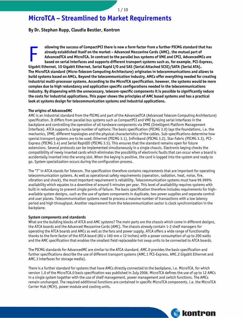
ollowing the success of CompactPCI there is now a form factor from a further PICMG standard that has already established itself on the market – Advanced Mezzanine Cards (AMC), the mutual part of AdvancedTCA and MicroTCA. In contrast to the parallel bus systems of VME and CPCI, AdvancedMCs are based on serial interfaces and supports different transport systems such as, for example, PCI-Express,
Gigabit Ethernet, 10 Gigabit Ethernet, Serial Rapid I/O and SAS (Serial Attached SCSI)/SATA (Serial ATA).
F The MicroTCA standard (Micro-Telecom Computing Architecture) originates in telecommunications and allows to build systems based on AMCs. Beyond the telecommunication industry, AMCs offer everything needed for creating industrial multi-processor systems. According to the MicroTCA specification, however, the systems would be more complex due to high redundancy and application specific configurations needed in the telecommunications industry. By dispensing with the unnecessary, telecom-specific components it is possible to significantly reduce the costs for industrial applications. This paper shows the principles of AMC based systems and has a practical look at systems design for telecommunication systems and industrial applications. The origins of AdvancedMC AMC is an industrial standard from the PICMG and part of the AdvancedTCA (Advanced Telecom Computing Architecture) specification. It differs from parallel bus systems such as CompactPCI and VME by using serial interfaces in the backplane and controlling the operation of all hardware components via IPMI (Intelligent Platform Management Interface). ATCA supports a large number of options: The basis specification (PICMG 3.0) lays the foundations, i.e. the mechanics, IPMI, different topologies and the physical characteristics of the cables. Sub-specifications determine how special transport systems are to be used: Ethernet (PICMG 3.1), Infiniband (PICMG 3.2), Star Fabric (PICMG 3.3), PCI-Express (PICMG 3.4) and Serial RapidIO (PICMG 3.5). This ensures that the standard remains open for future extensions. Several protocols can be implemented simultaneously in a single chassis. Electronic keying checks the compatibility of newly inserted cards which eliminates the possibility of electronic faults that can occur when a board is accidentally inserted into the wrong slot. When the keying is positive, the card is logged into the system and ready to go. System specialization occurs during the configuration process. The “T” in ATCA stands for Telecom. The specification therefore contains requirements that are important for operating telecommunication systems. As well as operational safety requirements (operation, radiation, heat, noise, fire, vibration and shock), the most important requirement is reliability. Telecommunication systems must have 99.999% availability which equates to a downtime of around 5 minutes per year. This level of availability requires systems with built in redundancy to prevent single points of failure. The basis specification therefore includes requirements for high-available system designs, such as the use of system components in duplicate, two power supplies and separate control and user planes. Telecommunication systems need to process a massive number of transactions with a low latency period and high throughput. Another requirement from the telecommunication sector is clock synchronization in the backplane. System components and standards What are the building blocks of ATCA and AMC systems? The main parts are the chassis which come in different designs, the ATCA boards and the Advanced Mezzanine Cards (AMC). The chassis already contain 1-2 shelf managers for operating the ATCA boards and AMCs as well as the fans and power supply. ATCA offers a wide range of functionality thanks to the form factor of the ATCA board (8U x 160 mm x 12 inches) with a power consumption of up to 200 watts and the AMC specification that enables the smallest field replaceable hot swap units to be connected to ATCA boards. The PICMG standards for AdvancedMC are similar to the ATCA standard. AMC.0 provides the basis specification and further specifications describe the use of different transport systems (AMC.1 PCI-Express, AMC.2 Gigabit Ethernet and AMC.3 interfaces for storage media). There is a further standard for systems that have AMCs directly connected to the backplane, i.e. MicroTCA, for which version 1.0 of the MicroTCA.0 basis specification was published in July 2006. MicroTCA defines the use of up to 12 AMCs in a single system together with the use of shelf management, power management and switch functions. The AMCs remain unchanged. The required additional functions are contained in specific MicroTCA components, i.e. the MicroTCA Carrier Hub (MCH), power module and cooling units.
2 / 10
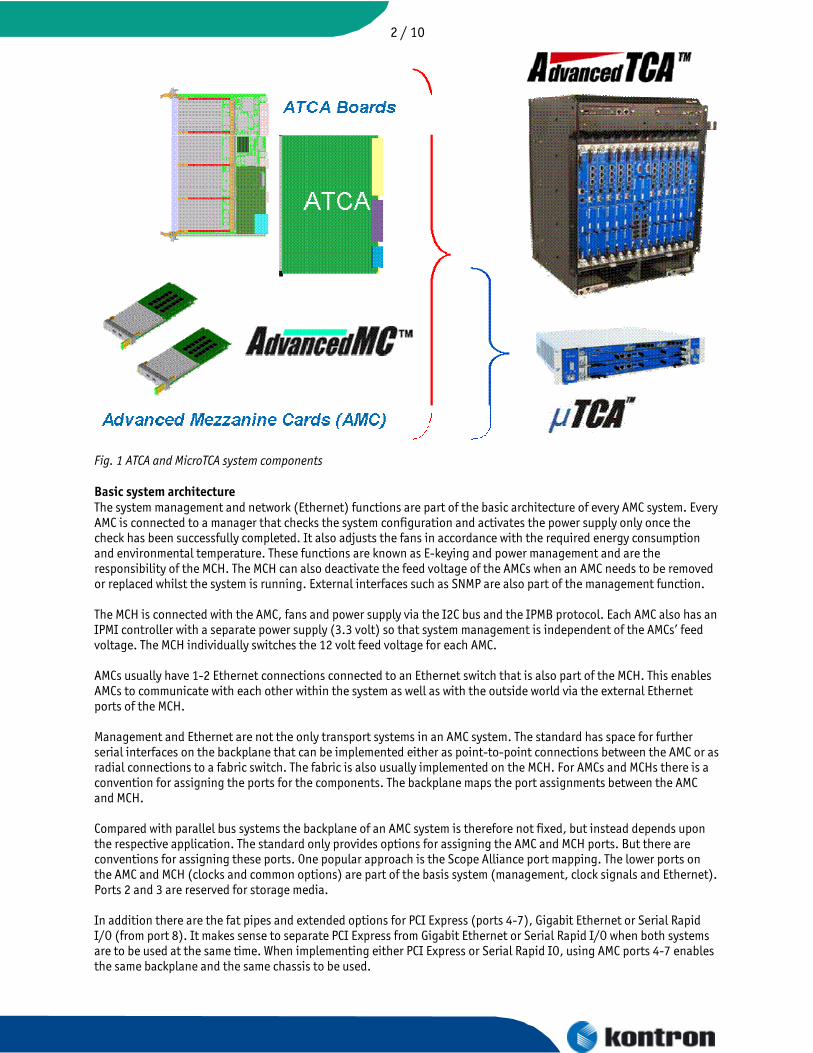
Fig. 1 ATCA and MicroTCA system components Basic system architecture The system management and network (Ethernet) functions are part of the basic architecture of every AMC system. Every AMC is connected to a manager that checks the system configuration and activates the power supply only once the check has been successfully completed. It also adjusts the fans in accordance with the required energy consumption and environmental temperature. These functions are known as E-keying and power management and are the responsibility of the MCH. The MCH can also deactivate the feed voltage of the AMCs when an AMC needs to be removed or replaced whilst the system is running. External interfaces such as SNMP are also part of the management function. The MCH is connected with the AMC, fans and power supply via the I2C bus and the IPMB protocol. Each AMC also has an IPMI controller with a separate power supply (3.3 volt) so that system management is independent of the AMCs’ feed voltage. The MCH individually switches the 12 volt feed voltage for each AMC. AMCs usually have 1-2 Ethernet connections connected to an Ethernet switch that is also part of the MCH. This enables AMCs to communicate with each other within the system as well as with the outside world via the external Ethernet ports of the MCH. Management and Ethernet are not the only transport systems in an AMC system. The standard has space for further serial interfaces on the backplane that can be implemented either as point-to-point connections between the AMC or as radial connections to a fabric switch. The fabric is also usually implemented on the MCH. For AMCs and MCHs there is a convention for assigning the ports for the components. The backplane maps the port assignments between the AMC and MCH. Compared with parallel bus systems the backplane of an AMC system is therefore not fixed, but instead depends upon the respective application. The standard only provides options for assigning the AMC and MCH ports. But there are conventions for assigning these ports. One popular approach is the Scope Alliance port mapping. The lower ports on the AMC and MCH (clocks and common options) are part of the basis system (management, clock signals and Ethernet). Ports 2 and 3 are reserved for storage media. In addition there are the fat pipes and extended options for PCI Express (ports 4-7), Gigabit Ethernet or Serial Rapid I/O (from port 8). It makes sense to separate PCI Express from Gigabit Ethernet or Serial Rapid I/O when both systems are to be used at the same time. When implementing either PCI Express or Serial Rapid IO, using AMC ports 4-7 enables the same backplane and the same chassis to be used.
3 / 10 Additional capacity with PCIe, SRIO and 10GbE Just like PC systems, processor AMCs can be connected with peripheral AMCs via PCI Express (PCIe). The AMC standard defines a clock line (fabric clock or CLK3) for operating PCI Express as well as data lines for PCI Express with 1 – 4 serial connections. In the simplest case, the PCI Express connections are implemented as point-to-point connections on the backplane. As an alternative to point-to-point connections the PCI Express connections can be routed to the MCH and from there to the AMC slots. In this case the MCH needs to have a PCI Express switch. The AMC standard offers further optional ports for additional connections between the AMCs in a single system. This includes further Ethernet connections (1 Gigabit Ethernet per AMC port or 10 Gigabit Ethernet with four AMC ports) and Serial Rapid I/O (SRIO, also with 10 Gigabits per second for four AMC ports) or 10 Gigabit Ethernet (10 GbE currently via combination of 4 ports). The additional capacity is implemented via the MCH and is most likely needed for processor communication in a multi-processor system. Depending on the system configuration, one or more MCHs with an Ethernet switch or SRIO switch could be used. Whereas Ethernet usually requires a switch for the basis system or for additional capacity, PCIe can run as a periphery bus directly via the backplane, including PCIe clocks. As usual for CompactPCI, there is a CPU slot for the PCIe connection. When it comes to PCIe, the four neighboring slots are for periphery cards. This specialization is, however, only valid for PCIe. Since the basis system already offers Ethernet, a processor can be placed on every slot. The slots can be connected to each other via the Ethernet network. Market Requirements Within Telecommunication Networks, MicroTCA applies to systems with smaller subscriber densities and within access networks. Among the typical applications are Signaling Gateways, Radio Network Controller (RNC), WiMAX Access Controller (WAC), Base Station (BTS, Node B; WiMAX) and IP-PBX Media Server. Outside of public networks, MicroTCA facilitates the implementation of Professional Mobile Radio systems, such as Tetra and P25. While the subscriber density is low in comparison with public networks, every network switch needs to be without single point of failure, i.e. each component needs to be duplicated. Other areas of applications with the same requirements as communication systems are military systems for radar, sonar, image processing and communications, as well as in aerospace. Among the applications in the industrial segment are high-performance processing with low latency, which typically need multi-processor systems. Typical applications are image processing and motion control in industry automation, image processing for medical diagnosis and therapy systems, and infotainment systems in transportation. While the functional requirements within the communication segment and the industrial segment may be similar, the non-functional requirements are entirely different: (1) Communications Segment:
• Carrier Grade Availability: No Single Point of Failure • Field Replaceable Units • Advanced management concept incl. exterior interfaces • Central Office Environment & Regulatory • Multi-Processor Network with high traffic throughput
(2) Industrial Segment (incl. Medical & Transportation) • Cost Optimized Solutions • No redundancy at module level • Field Replaceable Units and Mngt. optional (if at no extra expense) • Industrial Environment & Regulatory • Multi-Processor & industrial type of I/O
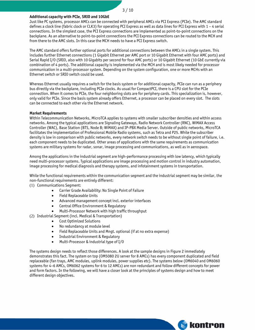
The systems design needs to reflect those differences. A look at the sample designs in Figure 2 immediately demonstrates this fact. The system on top (OM5080 2U server for 8 AMCs) has every component duplicated and field replaceable (fan trays, AMC modules, uplink modules, power supplies etc). The systems below (OM6040 and OM6060 systems for 4–6 AMCs, OM6062 systems for 6 to 12 AMCs) are non redundant and follow different concepts for power and form factors. In the following, we will have a closer look at the principles of systems design and how to meet different design objectives.

4 / 10
Fig 2 System design reflects different market requirements Micro TCA Systems Design - Management According to the MicroTCA standard, the management functions of an AMC based system includes (1) Power & Cooling (depending on load and environment), (2) Electronic Keying (matching configuration) & Hot-Swap for AMCs, (3) the provision of external management interfaces (over Terminal or Network). In as sample implementation as indicated in Figure 3, those functions are allocated to the MCH. For E-Keying, the MCH reads backplane config and talks over IPMI to AMCs (E-Keying) . For Power Management, the MCH talks over IPMI to Power Module and Cooling Unit. Also, the MCH provides the software and interfaces for external management via local terminals, network terminals, and over HPI and SNMP.
Fig. 3 MicroTCA Management View The MicroTCA standard assumes Power Modules and Cooling Units that are accessible from the MCH over a higher-level protocol, IPMI, over the I2C bus. This way, the power supply and fan unit need a microcontroller and corresponding software for the IPMI protocol. Power Modules are assumed to be provided in AMC form factor as field replaceable units. Such a type of implementation adds extra space and complexity to a system, which is not always desired. Figure 4 shows the principle including alternative options.
Fig. 4 Options for Management

5 / 10 In the upper left, the basic principle of management according to the MicroTCA standard is shown. The MCH accesses the configuration data on the backplane via I2C, the AMCs for E-Keying over IPMI (via the IPMB-L bus), and the Power Modules and Cooling Units also over IPMI (via the IPMB-0 bus). In a simplified design, the circuits for power switches and fan control can be placed on the backplane, as shown on the upper right in Figure 4. This allows the use of conventional power supplies from the market and is more in line with cooling concepts in industrial chassis. However, placing a microcontroller on the backplane to handle the IPMI protocol towards the MCH has the drawback of handling software updates on backplanes, which is out of scope for current design practice. One way to overcome this situation is to have the MCH control power and fans at a lower protocol layer, i.e. directly over I2C rather than over IPMI. This solution is shown in the upper right of Figure 4. While handling AMCs is entirely in line with the AMC and MicroTCA standard, power and fan control over I2C is not standardized. The corresponding SW part within the MCH represents a proprietary solution. The solution shown in the lower left in Figure 4 is moving power and cooling within the standard again. The MCH controls power and fans via IPMI. A Compatibility Module (CM) within the system terminates the protocol and translates it to system specific I2C commands. MicroTCA Systems Design – Network The next essential part of an AMC system according to the MicroTCA standard is network connectivity between AMCs. The MCH contains and Ethernet switch as integral part of the system, which also provides external ports (Uplinks in Figure 5). The standard feature set of MicroTCA, i.e. the Common Options part has GbE (Gigabit Ethernet) on AMC ports 0 and 1, as well as on MCH Fabric A.
Fig. 5 Network View Telecommunication systems usually require a managed Ethernet switch, which can do VLAN (Virtual LANs to separate traffic), QoS (Quality of Service, i.e. different priorities and handling for Ethernet frames), or switching according to IP-Source/Destination. In addition to a more expensive chip for the switch, a managed switch also needs an additional microcontroller as switch controller, and the corresponding software for configuration and management. The cheaper option for industrial applications represents an unmanaged switch. MicroTCA Systems Design - Fabrics The third major component of AMCs systems according to the MicroTCA standard are additional fabrics, such as PCI-Express (PCIe), more GbE or 10 GbE, or SRIO. The concept of PCIe is familiar from CompactPCI. The major differences are, that PCIe uses a serial interface rather than a parallel bus and that the configuration is managed by E-Keying. Thus, MicroTCA is more flexible or less defined: it provides more options for configuration. One way of connecting multiple AMCs over PCIe is to use a PCIe switch, as shown in Figure 6. With a PCIe switch, the system definition depends on the MCH: there are no fixed system slots: any slot can be Root (system) or node (e.g. I/O). The cheaper option where this kind of flexibility is not needed is to use Point-to-Point PCIe lanes & Clocks on backplane.
Fig. 6 Fabric for PCIe In addition to Network & Peripherals over PCIe, MicroTCA allows extra capacity for high data throughput over SRIO or 10 GbE. Switches can be implemented on the MCH using Fabric D E F G. At the AMC the corresponding ports typically are ports 8-11. Depending on the backplane, different topoligies can be provided for the extra fabric. Figure 7 shows a single-star and dual-star topology for up to 12 AMCs. Of course, if not all AMC slots need extra fabric; the design can be simplified and reduced to the ports actually needed. If it can be justified by volume, such an optimization means customized backplanes.

6 / 10
Fig. 7 Fabric for 10GbE and SRIO Carrier Grade Systems While the design principles are the same, implementations including the non-functional requirements lead to different designs in each market segment. As example, we have a closer look at the OM5080 Carrier Grade Platform (see Figure 8). The OM5080 is a 2U server for 8 AMCs in 19” housing. It has no single point-of-failure and each component is field-replaceable.
Fig. 8 OM5080 Carrier Grade Platform The OM5080 consists of 2U ATCA chassis with AT840xM ATCA Carrier boards, which host the AMCs. Thus, the system is closest to the origin of the MicroTCA standard, which essentially translates the ATCA carrier concepts to an autonomous system with AMCs on a backplane. On order to provide the extra functionality beyond the ATCA carrier, the OM5080 contains a portable software extension for AT840x for Shelf Management Functions (e.g. advanced fan control). It also adds some features, which are part of ATCA, but missing in the MicroTCA standard: (1) Shelf Alarm Panel on Management Module, (2) Uplink Modules (1G and/or 10G). In MicroTCA, the MCH is intended to provide the uplink capacity. However, due to the AMC form factor, front space is limited for high uplink capacity. The use of Uplink Modules eliminates this bottleneck: The OM5080 provides 8x GbE uplinks (or alternatively 2x 10 GbE plus 4x GbE). In addition, the OM5080 provides space for two ATCA RTM for I/O extensions (optional) and dual power feeds and power distribution. Figure 9 shows the system architecture.
Fig. 9 OM5080 Architecture – 1 GbE Version
7 / 10 From a conceptual point of view, the ATCA carrier represents an MCH plus PM. As network capacity, the 1GbE version of the OM5080 provides one uplink per AMC, which can be configured in transparent mode. The system represents a fully redundant configuration with 8x GbE interlink capacity between carriers. The carriers of the 1 GbE version also provide extra fabric capacity: 4 lanes of PCIe are available between AMCs and between Carriers (via update channel), there is SAS/SATA between AMCs and between Carriers, as well as Telco clocks. At the rear, the OM5080 provides two RTM slots which can be used with an RTM providing an external HDD and external SAS connection. The OM5080 provides power management and fan control as in ATCA systems. It also provides connectivity to telecom alarms, as well as connectivity to external management over SNMP.
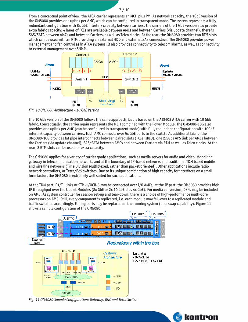
Fig. 10 OM5080 Architecture – 10 GbE Version The 10 GbE version of the OM5080 follows the same approach, but is based on the AT8402 ATCA carrier with 10 GbE fabric. Conceptually, the carrier again represents the MCH combined with the Power Module. The OM5080-10G also provides one uplink per AMC (can be configured in transparent mode) with fully redundant configuration with 10GbE interlink capacity between carriers. Each AMC connects over 5x GbE ports to the switch. As additional fabric, the OM5080-10G provides fat pipe interconnects between paired slots (PCIe, sRIO), one 2.5Gbs APS link per AMCs between the Carriers (via update channel), SAS/SATA between AMCs and between Carriers via RTM as well as Telco clocks. At the rear, 2 RTM slots can be used for extra capacity. The OM5080 applies for a variety of carrier grade applications, such as media servers for audio and video, signalling gateway in telecommunication networks and at the boundary of IP-based networks and traditional TDM based mobile and wire line networks (Time Division Multiplexed, rather than packet oriented). Other applications include radio network controllers, or Tetra/P25 switches. Due to its unique combination of high capacity for interfaces on a small form factor, the OM5080 is extremely well suited for such applications. At the TDM part, E1/T1 links or STM-1/OCR-3 may be connected over I/O AMCs, at the IP part, the OM5080 provides high IP throughput over the Uplink Modules (8x GbE or 2x 10 GbE plus 4x GbE). For media conversion, DSPs may be included on AMC. As system controller for session set-up and tear-down, there is a choice of high-performance multi-core processors on AMC. Still, every component is replicated, i.e. each module may fail-over to a replicated module and traffic switched accordingly. Failing parts may be replaced on the running system (hop-swap capability). Figure 11 shows a sample configuration of the OM5080.
Fig. 11 OM5080 Sample Configuration: Gateway, RNC and Tetra Switch
8 / 10 In the upper part, a schematic of the OM5080 is shown. Each of the AMC carriers contain one system controller (CPU on AMC), one media processor (DSP on AMC), and 2 I/O cards (e.g. each with 8x E1/T1 interfaces). With a total of 16 E1 ports connecting to Tetra/P25 stations, the system can handle 480 concurrent voice streams. The Uplink Modules provide IP-connectivity at the IP-domain of the network, e.g. towards a SIP based switch controller and media gateway. The systems architecture is shown in the diagram in the lower part of Figure 11. In this case, all modules connect over Ethernet, i.e. the I/O cards represent intelligent I/O (e.g. over iTDM). In this case the DSPs convert media streams between TDM and IP based protocols (such as iTDM and RTP). The CPUs handle the session set-up and tear down, and control the system at application level. For high-availability, the OM5080 contains a pre-configured network with redundancy and fail-over at Layer 2, i.e. Ethernet with pre-configured VLANs and MSTP to repair broken links. At network Layer and application layer, there is a choice of mechanisms to provide master and slave configurations with synchronisation at process level and failover. Among the building blocks are open source tools in the environment of the Linux ecosystem, as well as commercial tools with comfortable configuration tools and management support. Cost savings for industrial applications As standards in the telecommunication sector the AMC and MicroTCA specifications are very stable and offer a reliable and long-lasting basis for systems. The functional requirements in industrial applications may also include high processing power, throughput or low latencies, such as in image processing, control and medical diagnostics, or data capture and data processing. However, the non-functional part concerning redundancy, environmental and regulatory is quite different. How can such applications implemented in a cost efficient way? While maintaining the MicroTCA management concept in place, the list of measures for an industrial implementation includes:
• No redundant components in the system • No MicroTCA power module: an active backplane handles the switching when AMC cards are inserted or
removed. It also controls the fans. • Cubic design for six AMCs or twelve AMCs simplifies cooling • Where possible, PCI Express lanes and clock signals on the backplane instead of a PCI switch • MCH reduced to management and Ethernet (Basis version: unmanaged switch) • Operation without MCH when Ethernet is not needed • Double-width format enables complete CPU including graphics and hard drive on an AMC. • Double-width format enables reuse of CompactPCI PMCs • Pluggable power supplies for different supply voltages and performances.
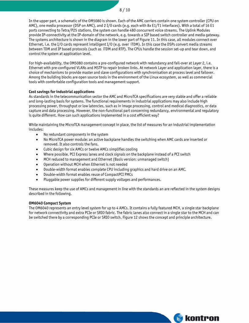
These measures keep the use of AMCs and management in line with the standards an are reflected in the system designs described in the following. OM6040 Compact System The OM6040 represents an entry level system for up to 4 AMCs. It contains a fully featured MCH, a single star backplane for network connectivity and extra PCIe or SRIO fabric. The fabric lanes also connect in a single star to the MCH and can be switched there by a corresponding PCIe or SRIO switch. Figure 12 shows the concept and principle architecture.
9 / 10
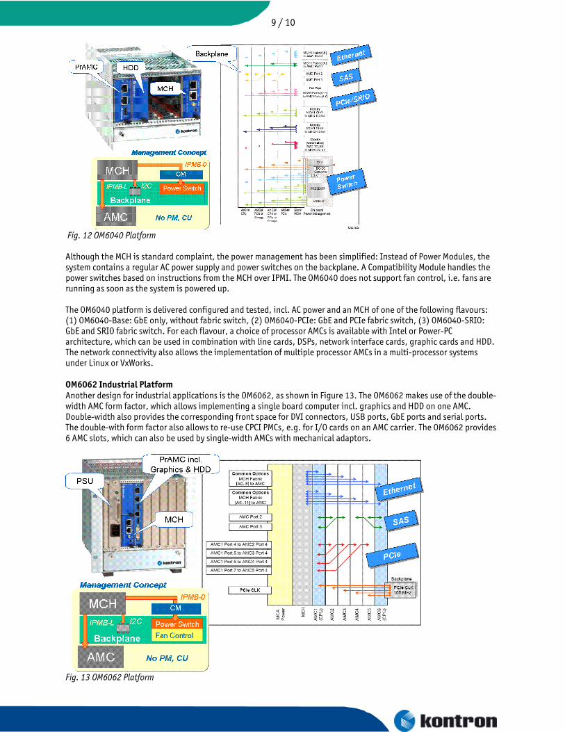
Fig. 12 OM6040 Platform Although the MCH is standard complaint, the power management has been simplified: Instead of Power Modules, the system contains a regular AC power supply and power switches on the backplane. A Compatibility Module handles the power switches based on instructions from the MCH over IPMI. The OM6040 does not support fan control, i.e. fans are running as soon as the system is powered up. The OM6040 platform is delivered configured and tested, incl. AC power and an MCH of one of the following flavours: (1) OM6040-Base: GbE only, without fabric switch, (2) OM6040-PCIe: GbE and PCIe fabric switch, (3) OM6040-SRIO: GbE and SRIO fabric switch. For each flavour, a choice of processor AMCs is available with Intel or Power-PC architecture, which can be used in combination with line cards, DSPs, network interface cards, graphic cards and HDD. The network connectivity also allows the implementation of multiple processor AMCs in a multi-processor systems under Linux or VxWorks. OM6062 Industrial Platform Another design for industrial applications is the OM6062, as shown in Figure 13. The OM6062 makes use of the double-width AMC form factor, which allows implementing a single board computer incl. graphics and HDD on one AMC. Double-width also provides the corresponding front space for DVI connectors, USB ports, GbE ports and serial ports. The double-with form factor also allows to re-use CPCI PMCs, e.g. for I/O cards on an AMC carrier. The OM6062 provides 6 AMC slots, which can also be used by single-width AMCs with mechanical adaptors.
Fig. 13 OM6062 Platform

10 / 10 Although not using MicroTCA Power Modules and Cooling units, the management concept of the OM6062 allows the use of any standard compliant MCH also for power management and fan control. Power switches and fan control circuits are placed on the backplane and controlled by the MCH over a compatibility module. The OM6062 is using conventional AC or DC power supplies in double-width, full-size AMC format. Power supplies are pluggable in order to provide a choice of options according to power consumption and input power. Backplanes in MicroTCA tend to become customer specific. The default backplane of the OM6062 contains PCIe clocks and PCIe lanes as point-to-point connections on the backplane, as outlined in Figures 13 (backplane topology) and Figre 14 (systems architecture). Point-to-point connections of single PCIe lanes routed to one CPU slot represents the most cost effective solution, of course, at the expense of flexibility. From a PCI perspective, not all AMC slots are equal: there is one CPU slot, which connects to 4 peripheral slots (see Figure 14, lower diagram).
Fig. 14: OM6062 Systems Architecture From a network perspective, all slots are equal and connect over Ethernet through the switch on the MCH. I order to provide more flexibility for PCIe, a different backplane layout is required, which allows the use of a PCIe switch. The same holds for the provision of extra fabric for 10 GbE or SRIO. Such backplane layouts and fabrics can be provided as options for customization. Summary and Outlook In summary, MicroTCA represents a versatile and stable standard which is particularly well suited for multi-processor systems. From a conceptual point of view MicroTCA includes the CPCI type of architecture and provides superior network capabilities for extra fabrics. Given its origin from telecommunications, MicroTCA includes an advanced management concept with support of E-Keying, power management, interfaces for external system management, and AMCs as Field Replaceable Units. The second generation of platforms now emerging on the market differentiates between carrier-grade platforms for communications and cost optimized platforms for industrial applications. With respect to cost improved designs, the standard provides sufficient flexibility. In this respect, management features are perceived as added value for industrial applications, not as cost driver. MicroTCA Power Modules and Cooling Units can be substituted in a way which maintains compatibility with management. Application specific form factors may be added, such as uplink modules to provide higher traffic connectivity and traffic capacity, or system alarm panels. In industrial applications, the double-width AMC form factor allows to implement single board computers on one PCB and extra front space for I/O (including the re-use of PMCs). Other options for cost reduction represent port optimized fabrics in combination with customer specific backplanes. In comparison with traditional parallel bus architectures, the concept of flexible backplanes is perhaps the biggest difference. In MicroTCA, the fixed parts are the AMC and MCH port mapping, along with the management protocols. The backplane layout represents a flexible part.