1 1.motivations 2.parameters, architecture, schedule, organisation 3.requirements for the ion source
TRANSCRIPT

1
Linac4 Status C. Carlipresenting (a slightly adopted selection of) slides prepared by and on behalf of M. Vretenar
6th Meeting of the joint CERN-Pakistan Committee7th June 2011
1. Motivations2. Parameters, Architecture,
Schedule, Organisation3. Requirements for the ion
source
2
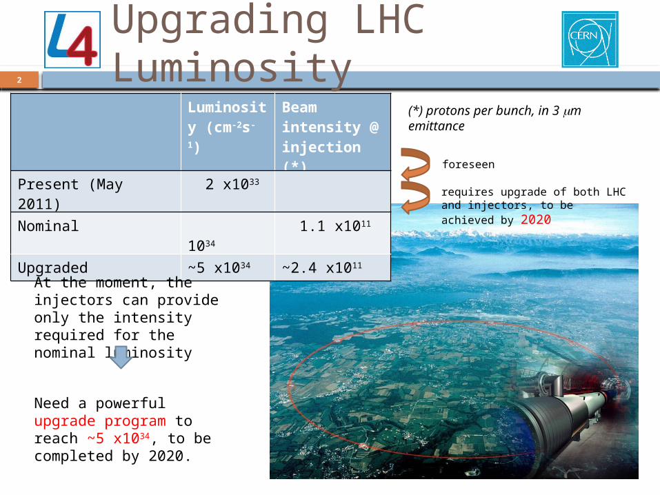
Upgrading LHC Luminosity
(*) protons per bunch, in 3 mm emittance
Luminosity (cm-2s-
1)
Beam intensity @ injection (*)
Present (May 2011) 2 x1033
Nominal 1034 1.1 x10¹¹
Upgraded ~5 x1034 ~2.4 x10¹¹
At the moment, the injectors can provide only the intensity required for the nominal luminosity
Need a powerful upgrade program to reach ~5 x1034, to be completed by 2020.
foreseen
requires upgrade of both LHC and injectors, to be achieved by 2020

3
Beam brightness and space charge
Linac2 (50 MeV)↓PS Booster (1.4 GeV)↓PS (25 GeV)↓SPS (450 GeV)↓LHC
parameters icrelativist classical :
raccelerato theof radiusmean :
emittances e transversnormalized :
nchprotons/bu ofnumber :with
,
2,
R
N
RNQ
YX
b
YX
bSC
LHC Injection chain: 4 accelerators
Tune shift from space charge (coulomb repulsion) is the main factor limiting brightness (and intensity) in a (circular) accelerator .
Highest tune shift at injection → The only cure against space charge is to go up in energy at injection (tune shift proportional to bg2).

4
Limitations to injector intensity
Three bottlenecks identified for higher intensity from the LHC injectors:1. Space charge tune shift at PSB
injection (50 MeV).2. Space charge tune shift at PS
injection (1.4 GeV).3. Electron cloud and other
instabilities in SPS.
Low injection energy into the PSB is the first and most important bottleneck →
Decision (CERN Council, June 2007) to build a new linac (Linac4) to increase energy from 50 to 160 MeV (no space for energy upgrade of Linac2).
Linac4 is positioned in a “free” area outside Restaurant 2, with easy connection to the PSB and providing space for future extension to higher energy.
1
2 3
Linac2 (50 MeV)↓PS Booster (1.4 GeV)↓PS (25 GeV)↓SPS (450 GeV)↓LHC

5
Linac4 architecture
No superconductivity (not economically justified in this range of beta’s and for our low duty cycle)
Normal conducting front-end for the SPL allows alleviating space charge bottleneck at PSB injection
Single RF frequency of 352 MHz (no sections at 704 MHz, standardised RF allows for considerable cost savings)
H- for injection in the PS Booster, chopping to minimize capture loss.
High efficiency, high reliability, flexible operation → three types of accelerating structures.
6
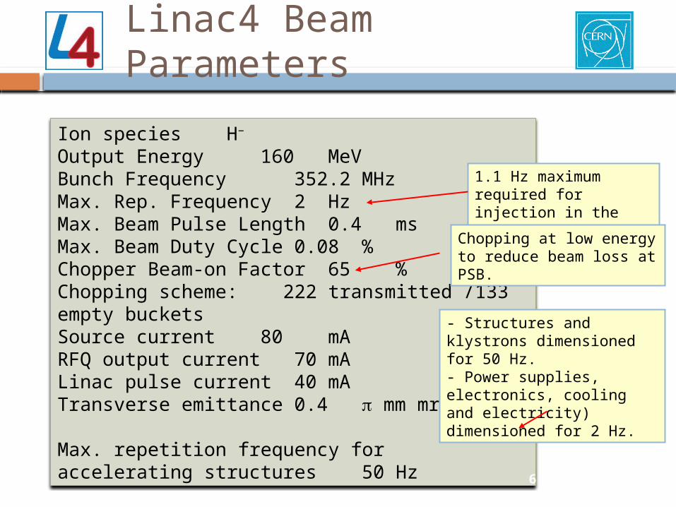
Linac4 Beam Parameters
Ion species H−
Output Energy 160 MeVBunch Frequency 352.2 MHzMax. Rep. Frequency 2 HzMax. Beam Pulse Length 0.4 msMax. Beam Duty Cycle 0.08 %Chopper Beam-on Factor 65 %Chopping scheme: 222 transmitted /133 empty bucketsSource current 80 mARFQ output current 70 mALinac pulse current 40 mATransverse emittance 0.4 p mm mrad
Max. repetition frequency for accelerating structures 50 Hz 6
- Structures and klystrons dimensioned for 50 Hz. - Power supplies, electronics, cooling and electricity) dimensioned for 2 Hz.
1.1 Hz maximum required for injection in the PSB
Chopping at low energy to reduce beam loss at PSB.

7
Linac4 – Low energy test stand
Ion source and LEBT assembled and under test.
Radio Frequency Quadrupole, in construction at CERN.
Chopping line built and tested (w/o beam).
LEP klystron (+ modulator) installed, tested in pulsed op.
Testing of RF structures at 2 Hz.
klystronmodulator
sourceRFQchopper line
diagnostics line
3 MeV TEST STAND in the PS South Hall – will be moved to Linac4 in 2013
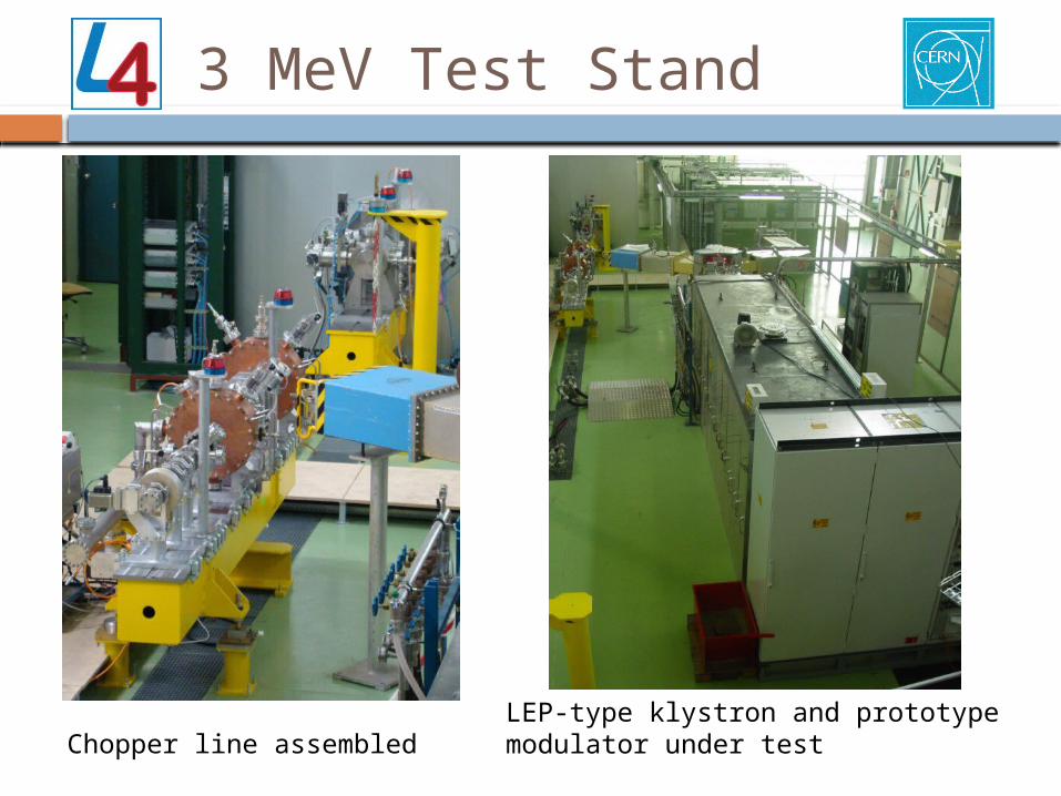
3 MeV Test Stand
Chopper line assembledLEP-type klystron and prototype modulator under test

9
The Linac4 RFQEnergy 3 MeV, length 3m, 3 section of 1 m each.
Brazed 4-vane design with simplified shape and cooling, for max. duty cycle 10%.
Construction entirely done at CERN: machining, metrology, brazing (horizontal).
Status: Modules #1 and #2 completed (2 brazing steps), Module #3 under final machining (brazings in June/July).
Program: RF tests in September/October 2011,RF conditioning October/November
2011,First beam end 2011.
module #1
module #3 after 2nd brazing
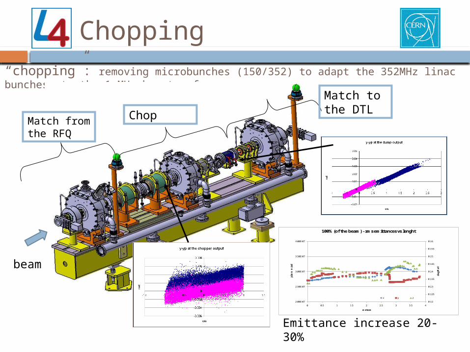
“chopping”: removing microbunches (150/352) to adapt the 352MHz linac bunches to the 1 MHz booster frequency
Match from the RFQ
Match to the DTLChop
0.12
0.125
0.13
0.135
0.14
0.145
0.15
0.155
0.16
2.00E-07
2.50E-07
3.00E-07
3.50E-07
4.00E-07
0 0.5 1 1.5 2 2.5 3 3.5 4
de
g M
eV
pi m
m m
rad
meters
100% (of the beam) - rms emittances vs lenght
x y z
Emittance increase 20-30%
Chopping
beam

Chopper line layout
Length 3.6 m
Already completed, installed in the test stand and tested without beam.
Chopper: 2 meander-line structures on ceramic substrate.
2.84 ns
PSB injection scheme (with energy ramping)
12
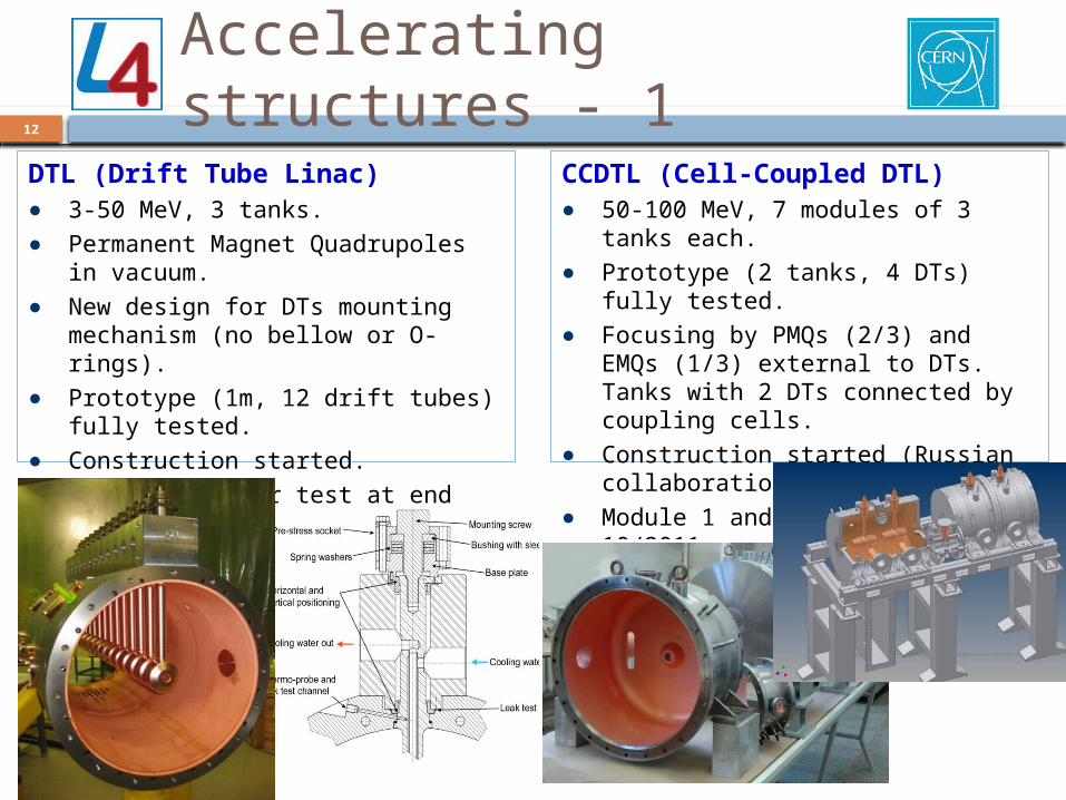
Accelerating structures - 1
DTL (Drift Tube Linac)● 3-50 MeV, 3 tanks.● Permanent Magnet Quadrupoles in
vacuum.● New design for DTs mounting
mechanism (no bellow or O-rings). ● Prototype (1m, 12 drift tubes) fully tested.● Construction started.● Tank1 ready for test at end 2011.
CCDTL (Cell-Coupled DTL)● 50-100 MeV, 7 modules of 3 tanks each.● Prototype (2 tanks, 4 DTs) fully tested.● Focusing by PMQs (2/3) and EMQs (1/3)
external to DTs. Tanks with 2 DTs connected by coupling cells.
● Construction started (Russian collaboration).
● Module 1 and 2 to be delivered 10/2011.

13
Accelerating structures - 2
PIMS (Pi-Mode Structure)● 100-160 MeV, 12 tanks of 7 cells each.● An efficient way to avoid the CCL…● Prototype fully tested. ● Focusing by external EMQs, tanks of 7
cells in pi-mode, coupling by 2 slots. Full-Cu elements, EB-welded.
● Construction started - collaboration Soltan (PL), FZ Julich (D), CERN.
coupling iris RF
window
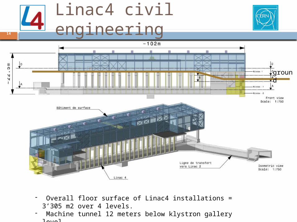
Linac4 civil engineering14
ground
- Overall floor surface of Linac4 installations = 3’305 m2 over 4 levels.- Machine tunnel 12 meters below klystron gallery level.- Access module at the low energy side.
15
“Mount-Citron”, September 2008
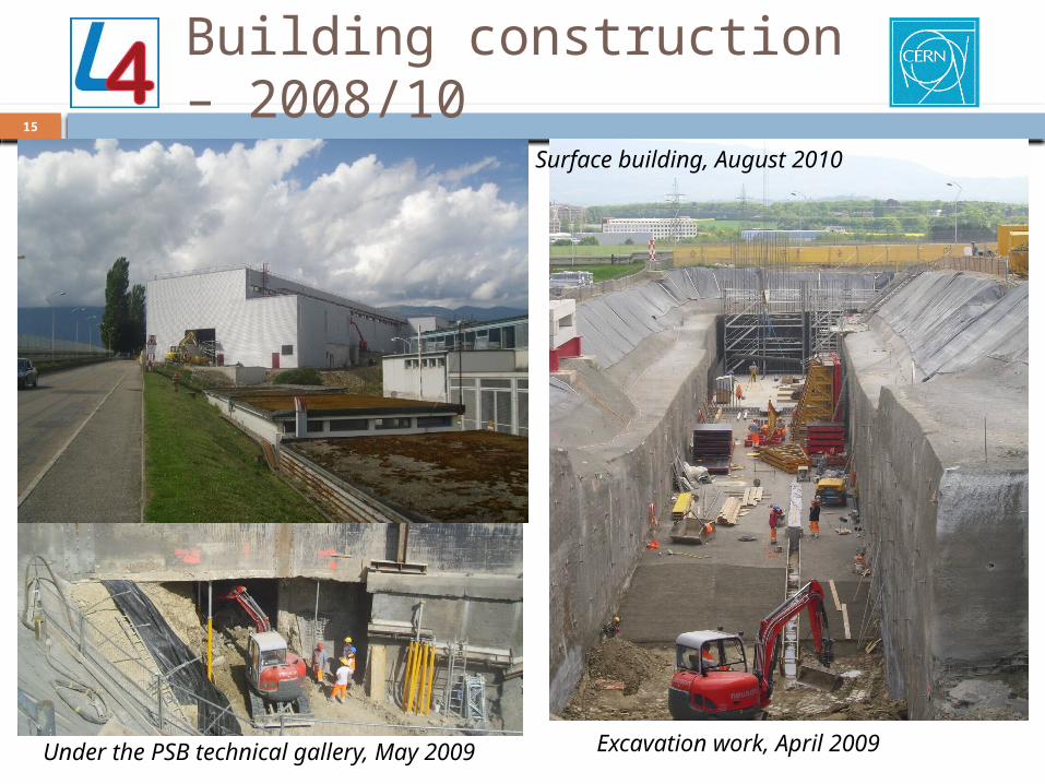
Building construction – 2008/10
Excavation work, April 2009
Surface building, August 2010
Under the PSB technical gallery, May 2009
16
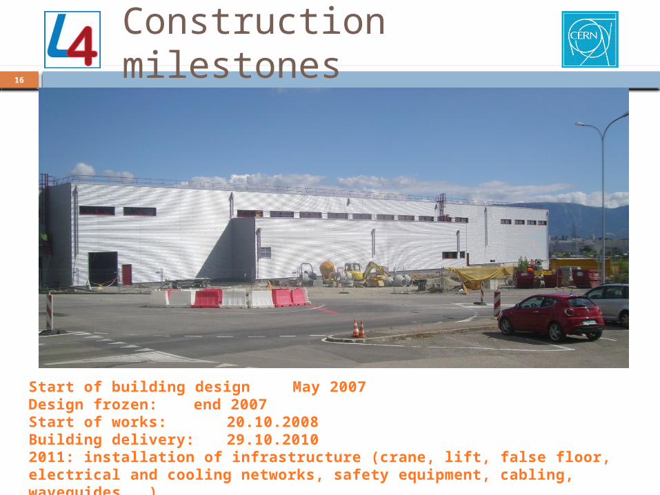
Construction milestones
Start of building design May 2007Design frozen: end 2007Start of works: 20.10.2008Building delivery: 29.10.20102011: installation of infrastructure (crane, lift, false floor, electrical and cooling networks, safety equipment, cabling, waveguides, …).

17
Status of Linac4 components
Ion source: present source converted to protons, tested, will be used on test stand to commission the RFQ. Design of new source started, main components ordered, first tests expected for September 2012. International review of source programme 7-8.6.11.
RFQ: 2/3 segments completed, 3rd being prepared for brazing (#1 June, #2 July). RF tuning foreseen in September/October, RF conditioning Nov./Dec.
DTL: Drift tubes and tanks in production, Tank1 expected to be assembled end 2011.
CCDTL: in construction in Russia, modules 1 and 2 (/7) ready in August 2011.
PIMS: production started in Poland.
Klystrons: first prototype (from Thales) expected at end 2011.
Modulators: see Francis’ presentation.
Quadrupoles: PMQs for DTL1 received and tested, for DTL2 and 3 ordered; call for tenders out for EMQs.
ion sourcemeasurements
DTL tank1 (before finishing and plating)

18
Linac4 – schedule
Building delivery
2011:Infrastructure installation
2012/13:Accelerat
or installatio
n
2013/14:Commissio
ning

19
Conclusions
● Linac4, to be completed by the end of 2014, will pave the way to the increase of the LHC luminosity. At the same time, it will replace Linac2 with a more modern and powerful machine and allow for high duty cycle operation for other applications.
● Civil engineering is completed, as well as the 3D full integration. Defined a construction strategy integrating industrial components and in-kind contributions. Construction of the main components is progressing.
● New designs and technologies have been developed for Linac4, aiming at efficiency, reliability, maintainability and low cost.
● The project is followed by modern project management tools, trying to minimize the overhead for the technical team.

20
Acknowledgements
This work is the result of the contribution of many different teams and persons. In particular, for the material of this talk I am grateful to:
Ion source: J. Lettry, R. Scrivens
RFQ: C. Rossi, S. Mathot, A. France (CEA), O. Piquet (CEA)
Chopper: F. Caspers, M. Paoluzzi
DTL: S. Ramberger, P. Bourquin, Y. Cuvet
CCDTL: F. Gerigk, A. Tribendis (BINP)
PIMS: R. Wegner, F. Gerigk, G. Favre, A. Dallocchio
Beam dynamics: A. Lombardi, J.B. Lallement, G. Bellodi
RF: O. Brunner, N. Schwerg
PS Booster: C. Carli, K. Hanke, W. Weterings
Civil engineering and integration: L.A. Lopez-H., J.-P. Corso
Project organization, EVM: S. Weisz, J. De Jonghe, J. Coupard

21
The end (for the moment),More slides if needed!

22
Linac4 tunnel
Linac4-Linac2 transfer line
Equipment building
Access building
Low-energy injector
ground level
Linac4 – basic parameters
1. Higher intensity in PSB for the LHC upgrade.2. More modern and sustainable machine than
Linac2 (worries for long-term operation of Linac2 – vacuum, RF).
3. Flexible operation and reduced loss with new technologies (chopping, H- injection).
4. Higher intensity for non-LHC users.5. Prepare for a possible high-intensity upgrade
(neutrino facility).
Energy 160 MeV factor 2 in bg2 from Linac2 x2 intensity in PSB with same tune shift (DQ~ N/bg2).
Use LEP RF frequency of 352 MHz recuperate some klystrons and RF equipment.
Repetition frequency 2 Hz (1.1 Hz max. PSB), possible future upgrade to 50 Hz.
Beam current 40 mA in 400 ms: >2 present PSB maximum.
duty cycle 0.8x10⁻³ designed for 10%
Note: Linac3 is the heavy-ion linac!

23
Options for the injectors upgrade
1. Old program (2008-09): a) replace the PSB with a high-energy linac (SPL=Superconducting Proton Linac, 4 GeV); b) replace the PS with a new PS2; c) upgrade the SPS. Expensive, high potential for luminosity (but SPS bottleneck), can be upgraded to high-intensity.
2. New program (2010): a) upgrade of PSB final energy to 2 GeV (possible with present magnets); b) consolidation of PS; c) upgrade (coating, new RF) of SPS. Lower potential luminosity increase, but less expensive and achievable in a shorter time.
3. Alternative intermediate option (being analyzed now): replace the PSB with a Rapid Cycling Synchrotron (RCS) at 2 GeV.
Linac4
SPL
SPS
LHC
PS2
A new linac (Linac4) is the first and essential element for an upgrade of the LHC luminosity.
But what after Linac4 ?
2 options have been compared, and a 3rd one is being analyzed.

Linac4 for the SPL24
H- source RFQ chopper DTL CCDTL PIMS
3 MeV 50 MeV 102 MeV
352.2 MHz
β=0.65
β=1.0
643 MeV 4/5 GeV
704.4 MHz
160 MeV
Linac4 (160 MeV) SC-linac (4/5 GeV)
Superconducting Proton Linac (SPL) study in progress at CERN extension of Linac4 to 4 or 5 GeV and upgrade to 6% duty cycleProject in the same category as Project-X at FNAL, high-intensity driver for neutrinos (Superbeam, Neutrino Factory) and/or Radioactive Ion Beams
~ 400 m
R&D for SPL is progressing (construction and test of a 4-cavity cryomodule) Synergy with ESS !

25
Completing the infrastructure

Accelerating structures construction
26
Construction of the Linac4 accelerating structure – an European enterprise (and beyond…)
Drift Tube Linac (DTL): prototype from INFN/LNL (Italy), drift tubes from ESS-Bilbao (Spain), tanks and assembly at CERN
Cell-Coupled DTL: tanks from VNIIEF (Snezinsk), drift tubes and assembling from BINP (Novosibirsk)
PI-Mode Structure (PIMS): tanks from Soltan Institute (Poland), EB welding from FZ Juelich (Germany), assembly and final EB welding at CERN.

27
Linac4 – External Contributions
H-source RFQ DTL
45 keV 3 MeV 50 MeV 100 MeV 160 MeV
chopper line CCDTL PIMS transfer line to PSBLEBT
80 m
Chopper line built in a EU Joint Research Activitycompleted
Participation of ESS-Bilbao in DTL construction, started
Construction of CCDTL in Russia, via an ISTC Project started
Collaboration agreement with Soltan Institute (Poland) for PIMS construction, started
Transfer line vacuum chambers and supports from Pakistan, agreed
Prototype modulator, waveguide couplers, alignment jacks from India, started
RFQ RF design, RF amplifiers, modulator construction from French Special Contribution, started.
Network of agreements to support Linac4 construction. Relatively small fraction of the overall budget, but access to specialized manpower and share of information with other teams. Integration at the component level.
28
Thank you for your attention !