1. (a) compare interstitial and vacancy atomic mechanisms ... · pdf file1. (a) compare...
TRANSCRIPT
1. (a) Compare interstitial and vacancy atomic mechanisms for diffusion.
(b) Cite two reasons why interstitial diffusion is normally more rapid than vacancy diffusion.
Solution
(a) With vacancy diffusion, atomic motion is from one lattice site to an adjacent vacancy. Self-
diffusion and the diffusion of substitutional impurities proceed via this mechanism. On the other hand,
atomic motion is from interstitial site to adjacent interstitial site for the interstitial diffusion mechanism.
(b) Interstitial diffusion is normally more rapid than vacancy diffusion because: (1) interstitial
atoms, being smaller, are more mobile; and (2) the probability of an empty adjacent interstitial site is
greater than for a vacancy adjacent to a host (or substitutional impurity) atom.
2. A sheet of steel 1.5 mm thick has nitrogen atmospheres on both sides at 1200°C and is permitted to
achieve a steady-state diffusion condition. The diffusion coefficient for nitrogen in steel at this temperature
is 6 × 10-11 m2/s, and the diffusion flux is found to be 1.2 × 10⁻⁷ kg/m2-s. Also, it is known that the
concentration of nitrogen in the steel at the high-pressure surface is 4 kg/m3. How far into the sheet from
this high-pressure side will the concentration be 2.0 kg/m3? Assume a linear concentration profile.
Solution
This problem is solved by using Equation 5.3 in the form
�
J = − DCA − CBxA − xB
If we take CA to be the point at which the concentration of nitrogen is 4 kg/m3, then it becomes necessary
to solve for xB, as
�
xB = xA + D CA − CB
J
⎡
⎣ ⎢
⎤
⎦ ⎥
Assume xA is zero at the surface, in which case
�
xB = 0 + (6 × 10-11 m2/s) 4 kg /m3 − 2 kg /m3
1.2 × 10⁻⁷ kg /m2 - s
⎡
⎣ ⎢
⎤
⎦ ⎥
= 1 × 10⁻³ m = 1 mm
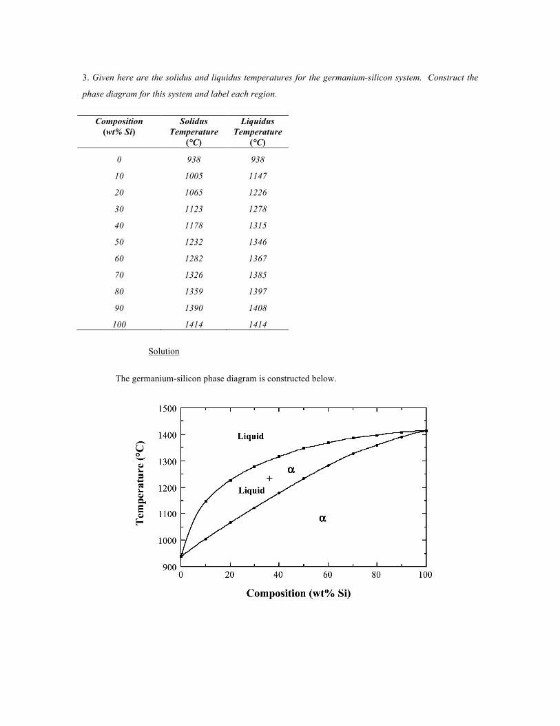
3. Given here are the solidus and liquidus temperatures for the germanium-silicon system. Construct the
phase diagram for this system and label each region.
Composition
(wt% Si) Solidus
Temperature (°C)
Liquidus Temperature
(°C)
0 938 938
10 1005 1147
20 1065 1226
30 1123 1278
40 1178 1315
50 1232 1346
60 1282 1367
70 1326 1385
80 1359 1397
90 1390 1408
100 1414 1414
Solution
The germanium-silicon phase diagram is constructed below.
4. Is it possible to have a copper–nickel alloy that, at equilibrium, consists of a liquid phase of composition
20 wt% Ni–80 wt% Cu and also an α phase of composition 37 wt% Ni–63 wt% Cu? If so, what will be the
approximate temperature of the alloy? If this is not possible, explain why.
Solution
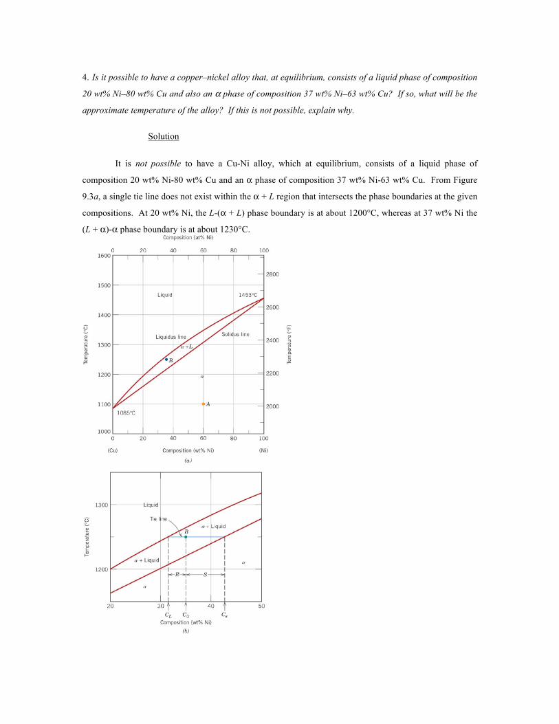
It is not possible to have a Cu-Ni alloy, which at equilibrium, consists of a liquid phase of
composition 20 wt% Ni-80 wt% Cu and an α phase of composition 37 wt% Ni-63 wt% Cu. From Figure
9.3a, a single tie line does not exist within the α + L region that intersects the phase boundaries at the given
compositions. At 20 wt% Ni, the L-(α + L) phase boundary is at about 1200°C, whereas at 37 wt% Ni the
(L + α)-α phase boundary is at about 1230°C.
5. A 50 wt% Pb-50 wt% Mg alloy is slowly cooled from 700°C (1290°F) to 400°C (750°F).
(a) At what temperature does the first solid phase form?
(b) What is the composition of this solid phase?
(c) At what temperature does the liquid solidify?
(d) What is the composition of this last remaining liquid phase?
Solution
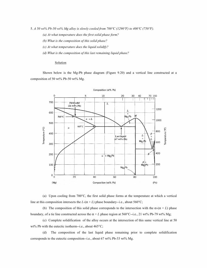
Shown below is the Mg-Pb phase diagram (Figure 9.20) and a vertical line constructed at a
composition of 50 wt% Pb-50 wt% Mg.
(a) Upon cooling from 700°C, the first solid phase forms at the temperature at which a vertical
line at this composition intersects the L-(α + L) phase boundary--i.e., about 560°C;
(b) The composition of this solid phase corresponds to the intersection with the α-(α + L) phase
boundary, of a tie line constructed across the α + L phase region at 560°C--i.e., 21 wt% Pb-79 wt% Mg;
(c) Complete solidification of the alloy occurs at the intersection of this same vertical line at 50
wt% Pb with the eutectic isotherm--i.e., about 465°C;
(d) The composition of the last liquid phase remaining prior to complete solidification
corresponds to the eutectic composition--i.e., about 67 wt% Pb-33 wt% Mg.
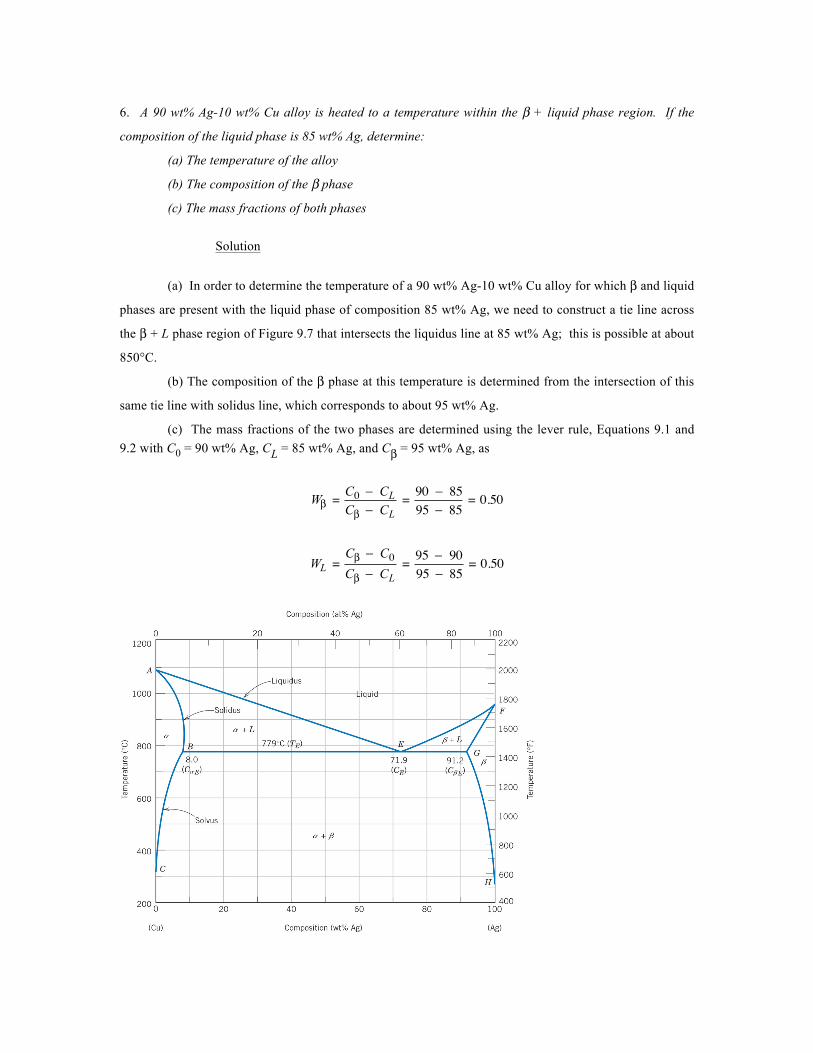
6. A 90 wt% Ag-10 wt% Cu alloy is heated to a temperature within the β + liquid phase region. If the
composition of the liquid phase is 85 wt% Ag, determine:
(a) The temperature of the alloy
(b) The composition of the β phase
(c) The mass fractions of both phases
Solution
(a) In order to determine the temperature of a 90 wt% Ag-10 wt% Cu alloy for which β and liquid
phases are present with the liquid phase of composition 85 wt% Ag, we need to construct a tie line across
the β + L phase region of Figure 9.7 that intersects the liquidus line at 85 wt% Ag; this is possible at about
850°C.
(b) The composition of the β phase at this temperature is determined from the intersection of this
same tie line with solidus line, which corresponds to about 95 wt% Ag.
(c) The mass fractions of the two phases are determined using the lever rule, Equations 9.1 and 9.2 with C0 = 90 wt% Ag, CL = 85 wt% Ag, and Cβ = 95 wt% Ag, as
�
Wβ =C0 − CLCβ − CL
= 90 − 8595 − 85
= 0.50
�
WL =Cβ − C0Cβ − CL
= 95 − 9095 − 85
= 0.50
7. What is the carbon concentration of an iron–carbon alloy for which the fraction of total ferrite is 0.94?
Solution
This problem asks that we compute the carbon concentration of an iron-carbon alloy for which the
fraction of total ferrite is 0.94. Application of the lever rule (of the form of Equation 9.12) yields
�
Wα = 0.94 =CFe3C − C0'
CFe3C − Cα=
6.70 − C0'
6.70 − 0.022
and solving for
�
C0'
�
C0' = 0.42 wt% C
8. What is the proeutectoid phase for an iron–carbon alloy in which the mass fractions of total ferrite and
total cementite are 0.92 and 0.08, respectively? Why?
Solution
In this problem we are given values of Wα and WFe3C (0.92 and 0.08, respectively) for an iron-
carbon alloy and then are asked to specify the proeutectoid phase. Employment of the lever rule for total α
leads to
�
Wα = 0.92 =CFe3C − C0CFe3C − Cα
= 6.70 − C06.70 − 0.022
Now, solving for C0, the alloy composition, leads to C0 = 0.56 wt% C. Therefore, the proeutectoid phase is
α-ferrite since C0 is less than 0.76 wt% C.
9. Consider 1.0 kg of austenite containing 1.15 wt% C, cooled to below 727°C (1341°F).
(a) What is the proeutectoid phase?
(b) How many kilograms each of total ferrite and cementite form?
(c) How many kilograms each of pearlite and the proeutectoid phase form?
(d) Schematically sketch and label the resulting microstructure.
Solution
(a) The proeutectoid phase will be Fe3C since 1.15 wt% C is greater than the eutectoid
composition (0.76 wt% C).
(b) For this portion of the problem, we are asked to determine how much total ferrite and
cementite form. Application of the appropriate lever rule expression yields
�
Wα =CFe3C − C0CFe3C − Cα
= 6.70 − 1.156.70 − 0.022
= 0.83
which, when multiplied by the total mass of the alloy (1.0 kg), gives 0.83 kg of total ferrite.
Similarly, for total cementite,
�
WFe3C =C0 − Cα
CFe3C − Cα= 1.15 − 0.0226.70 − 0.022
= 0.17
And the mass of total cementite that forms is (0.17)(1.0 kg) = 0.17 kg.
(c) Now we are asked to calculate how much pearlite and the proeutectoid phase (cementite)
form. Applying Equation 9.22, in which
�
C1' = 1.15 wt% C
�
Wp =6.70 − C 1
'
6.70 − 0.76= 6.70 − 1.156.70 − 0.76
= 0.93
which corresponds to a mass of 0.93 kg. Likewise, from Equation 9.23
�
WFe3C' =C1' − 0.765.94
= 1.15 − 0.765.94
= 0.07
which is equivalent to 0.07 kg of the total 1.0 kg mass.
(d) Schematically, the microstructure would appear as:

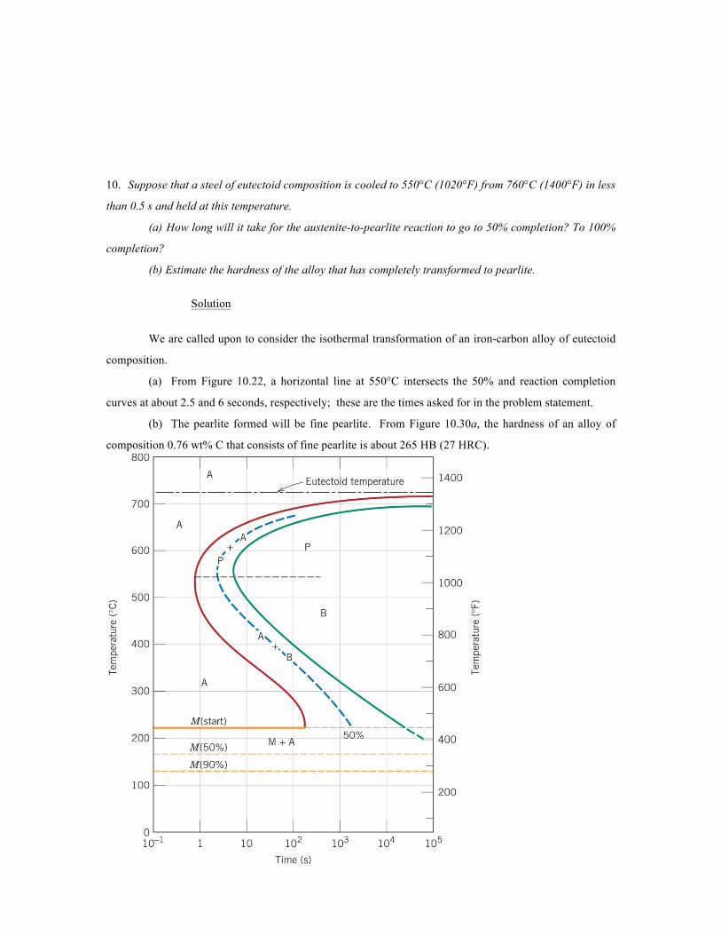
10. Suppose that a steel of eutectoid composition is cooled to 550°C (1020°F) from 760°C (1400°F) in less
than 0.5 s and held at this temperature.
(a) How long will it take for the austenite-to-pearlite reaction to go to 50% completion? To 100%
completion?
(b) Estimate the hardness of the alloy that has completely transformed to pearlite.
Solution
We are called upon to consider the isothermal transformation of an iron-carbon alloy of eutectoid
composition.
(a) From Figure 10.22, a horizontal line at 550°C intersects the 50% and reaction completion
curves at about 2.5 and 6 seconds, respectively; these are the times asked for in the problem statement.
(b) The pearlite formed will be fine pearlite. From Figure 10.30a, the hardness of an alloy of
composition 0.76 wt% C that consists of fine pearlite is about 265 HB (27 HRC).
11. Briefly cite the differences between pearlite, bainite, and spheroidite relative to microstructure and
mechanical properties.
Solution
The microstructures of pearlite, bainite, and spheroidite all consist of α-ferrite and cementite
phases. For pearlite, the two phases exist as layers which alternate with one another. Bainite consists of
very fine and parallel needle-shaped particles of cementite that are surrounded an α-ferrite matrix. For
spheroidite, the matrix is ferrite, and the cementite phase is in the shape of sphere-shaped particles.
Bainite is harder and stronger than pearlite, which, in turn, is harder and stronger than spheroidite.
12 Using the isothermal transformation diagram for a 0.45 wt% C steel alloy (Figure 10.39), determine
the final microstructure (in terms of just the microconstituents present) of a small specimen that has been
subjected to the following time-temperature treatments. In each case assume that the specimen begins at
845°C (1550°F), and that it has been held at this temperature long enough to have achieved a complete
and homogeneous austenitic structure.
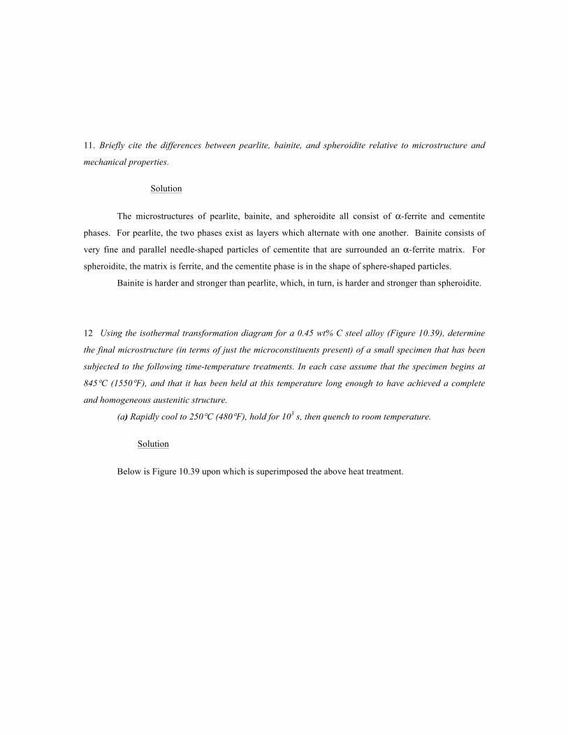
(a) Rapidly cool to 250°C (480°F), hold for 103 s, then quench to room temperature.
Solution
Below is Figure 10.39 upon which is superimposed the above heat treatment.
While rapidly cooling to 250°C about 80% of the specimen transforms to martensite; during the
1000 s isothermal treatment at 250°C no additional transformations occur. During the final cooling to room
temperature, the untransformed austenite also transforms to martensite. Hence, the final microstructure
consists of 100% martensite.
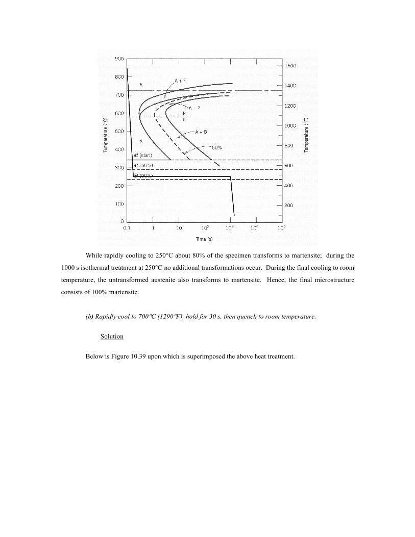
(b) Rapidly cool to 700°C (1290°F), hold for 30 s, then quench to room temperature.
Solution
Below is Figure 10.39 upon which is superimposed the above heat treatment.
After cooling to and holding at 700°C for 30 s, a portion of specimen has transformed to
proeutectoid ferrite. While cooling to room temperature, the remainder of the specimen transforms to
martensite. Hence, the final microstructure consists proeutectoid ferrite and martensite.
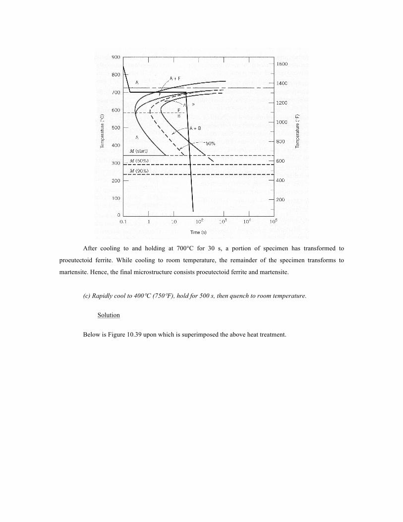
(c) Rapidly cool to 400°C (750°F), hold for 500 s, then quench to room temperature.
Solution
Below is Figure 10.39 upon which is superimposed the above heat treatment.
After cooling to and holding at 400°C for 500 s, all of the specimen has transformed to bainite.
Hence, the final microstructure consists of 100% bainite.
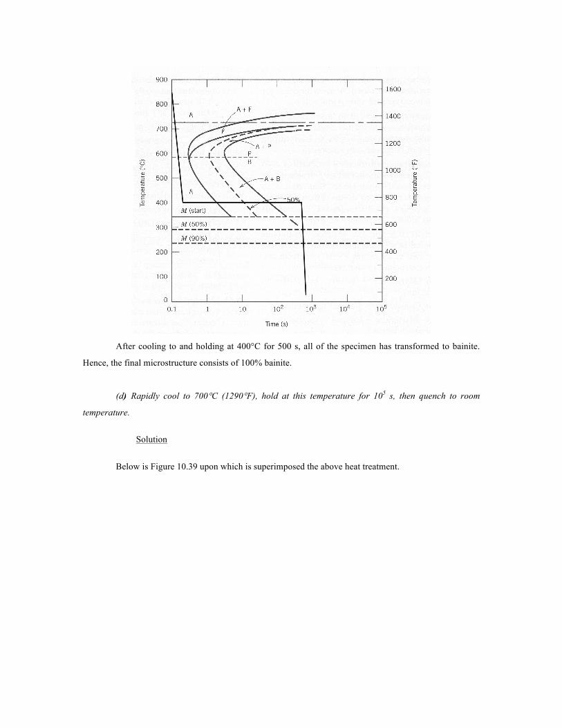
(d) Rapidly cool to 700°C (1290°F), hold at this temperature for 105 s, then quench to room
temperature.
Solution
Below is Figure 10.39 upon which is superimposed the above heat treatment.

After cooling to and while holding at 700°C the specimen first transforms to proeutectoid ferrite
and coarse pearlite. Continued heat treating at 700°C for 105 s results in a further transformation into
spheroidite. Hence, the final microstructure consists of 100% spheroidite.
(e) Rapidly cool to 650°C (1200°F), hold at this temperature for 3 s, rapidly cool to 400°C
(750°F), hold for 10 s, then quench to room temperature.
Solution
Below is Figure 10.39 upon which is superimposed the above heat treatment.
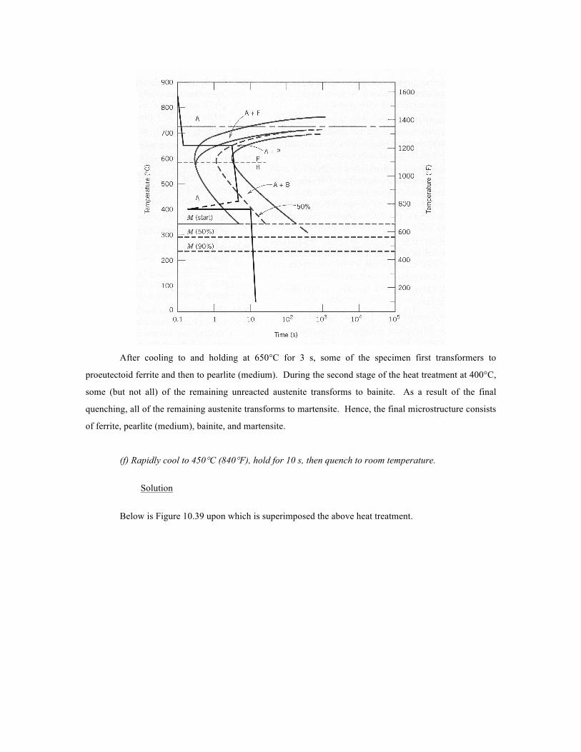
After cooling to and holding at 650°C for 3 s, some of the specimen first transformers to
proeutectoid ferrite and then to pearlite (medium). During the second stage of the heat treatment at 400°C,
some (but not all) of the remaining unreacted austenite transforms to bainite. As a result of the final
quenching, all of the remaining austenite transforms to martensite. Hence, the final microstructure consists
of ferrite, pearlite (medium), bainite, and martensite.
(f) Rapidly cool to 450°C (840°F), hold for 10 s, then quench to room temperature.
Solution
Below is Figure 10.39 upon which is superimposed the above heat treatment.
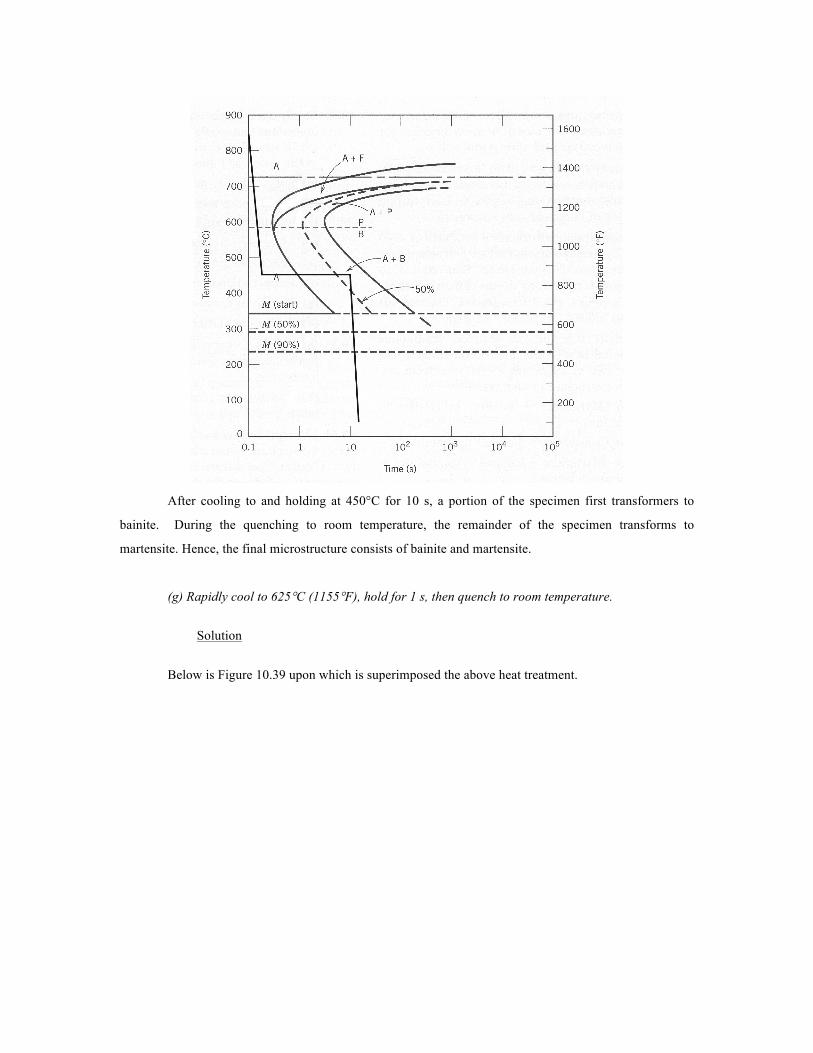
After cooling to and holding at 450°C for 10 s, a portion of the specimen first transformers to
bainite. During the quenching to room temperature, the remainder of the specimen transforms to
martensite. Hence, the final microstructure consists of bainite and martensite.
(g) Rapidly cool to 625°C (1155°F), hold for 1 s, then quench to room temperature.
Solution
Below is Figure 10.39 upon which is superimposed the above heat treatment.
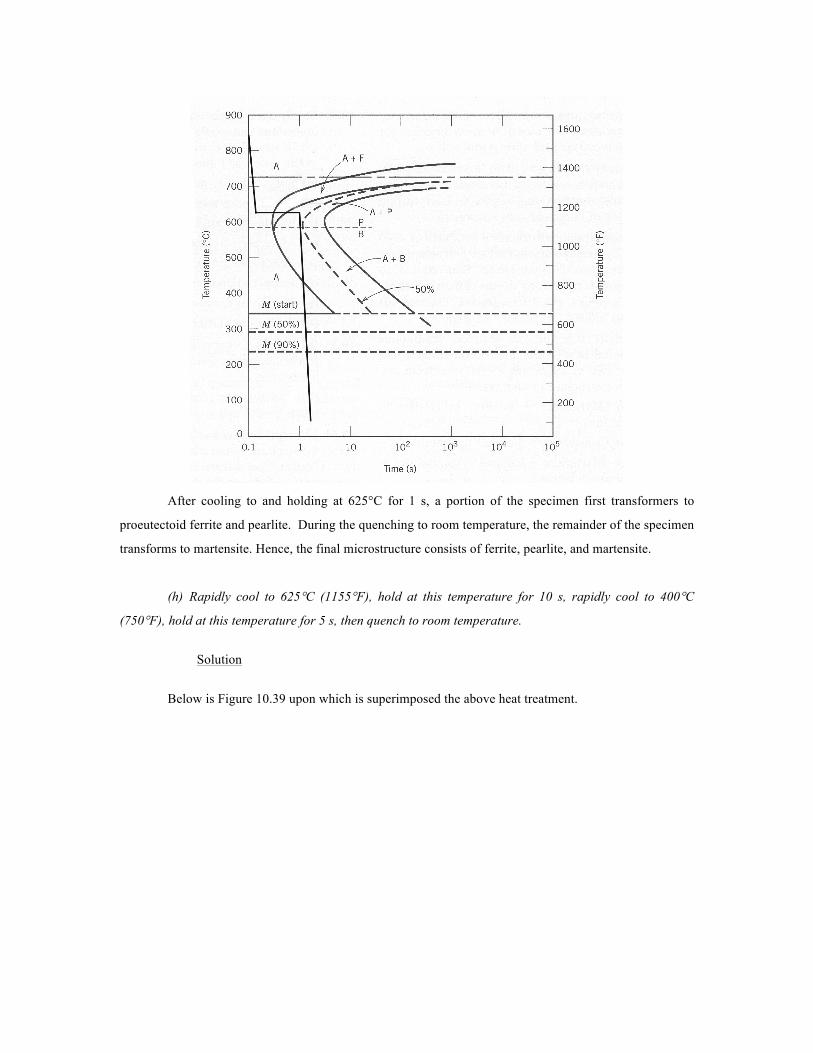
After cooling to and holding at 625°C for 1 s, a portion of the specimen first transformers to
proeutectoid ferrite and pearlite. During the quenching to room temperature, the remainder of the specimen
transforms to martensite. Hence, the final microstructure consists of ferrite, pearlite, and martensite.
(h) Rapidly cool to 625°C (1155°F), hold at this temperature for 10 s, rapidly cool to 400°C
(750°F), hold at this temperature for 5 s, then quench to room temperature.
Solution
Below is Figure 10.39 upon which is superimposed the above heat treatment.
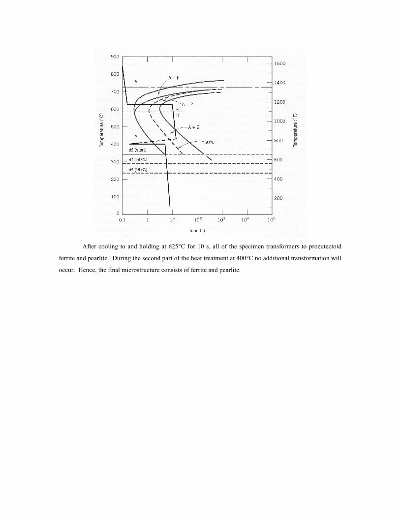
After cooling to and holding at 625°C for 10 s, all of the specimen transformers to proeutectoid
ferrite and pearlite. During the second part of the heat treatment at 400°C no additional transformation will
occur. Hence, the final microstructure consists of ferrite and pearlite.
13. Compare gray and malleable cast irons with respect to (a) composition and heat treatment, (b)
microstructure, and (c) mechanical characteristics.
Solution
This question asks us to compare various aspects of gray and malleable cast irons.
(a) With respect to composition and heat treatment:
Gray iron--2.5 to 4.0 wt% C and 1.0 to 3.0 wt% Si. For most gray irons there is no heat
treatment after solidification.
Malleable iron--2.5 to 4.0 wt% C and less than 1.0 wt% Si. White iron is heated in a
nonoxidizing atmosphere and at a temperature between 800 and 900°C for an extended time period.
(b) With respect to microstructure:
Gray iron--Graphite flakes are embedded in a ferrite or pearlite matrix.
Malleable iron--Graphite clusters are embedded in a ferrite or pearlite matrix.
(c) With respect to mechanical characteristics:
Gray iron--Relatively weak and brittle in tension; good capacity for damping vibrations.
Malleable iron--Moderate strength and ductility.
14. Compare white and nodular cast irons with respect to (a) composition and heat treatment, (b)
microstructure, and (c) mechanical characteristics.
Solution
This question asks us to compare white and nodular cast irons.
(a) With regard to composition and heat treatment:
White iron--2.5 to 4.0 wt% C and less than 1.0 wt% Si. No heat treatment; however,
cooling is rapid during solidification.
Nodular cast iron--2.5 to 4.0 wt% C, 1.0 to 3.0 wt% Si, and a small amount of Mg or Ce.
A heat treatment at about 700°C may be necessary to produce a ferritic matrix.
(b) With regard to microstructure:
White iron--There are regions of cementite interspersed within pearlite.
Nodular cast iron--Nodules of graphite are embedded in a ferrite or pearlite matrix.
(c) With respect to mechanical characteristics:
White iron--Extremely hard and brittle.
Nodular cast iron--Moderate strength and ductility.
15. Briefly explain the difference between hardness and hardenability.
Solution
Hardness is a measure of a material's resistance to localized surface deformation, whereas
hardenability is a measure of the depth to which a ferrous alloy may be hardened by the formation of
martensite. Hardenability is determined from hardness tests.
16. What influence does the presence of alloying elements (other than carbon) have on the shape of a
hardenability curve? Briefly explain this effect.
Solution
The presence of alloying elements (other than carbon) causes a much more gradual decrease in
hardness with position from the quenched end for a hardenability curve. The reason for this effect is that
alloying elements retard the formation of pearlitic and bainitic structures which are not as hard as
martensite.