1. a g e d ;:::;n g - northwestern...
TRANSCRIPT
1
ME 449 Robotic ManipulationFall 2014Problem Set 5Due Wednesday December 10 at noon. Bring your laptops for your final com-puter demo in the classroom at noon.
1. Implement an A∗ path planner. The planner takes a graph G as input, withN nodes and E edges. Edge ei is just a specification of the two nodes (i, j)it connects as well as the distance between the two nodes, dij . One possiblerepresentation of G is as a symmetric matrix, where Gij = Gji = 0 if there is noedge between i and j, and Gij = Gji = dij if there is an edge. Your A∗ plannershould return the sequence of nodes visited, {n1, n2, . . . , nk}, in the shortestpath, where n1 is the start node and nk is the goal node. If there is no solution,your code should indicate so. Turn in your well-commented code.
2. Now test your A∗ code on the case of a circular mobile robot moving amongN circular obstacles in a 100× 100 planar region.Input:
(i) the radius r of the robot
(ii) a list of radii ri and (xi, yi) coordinates of the centers of the obstacles
(iii) a list of (x, y) coordinates (the configuration of the center of the robot)for potential nodes of the graph
(iv) the start and goal nodes
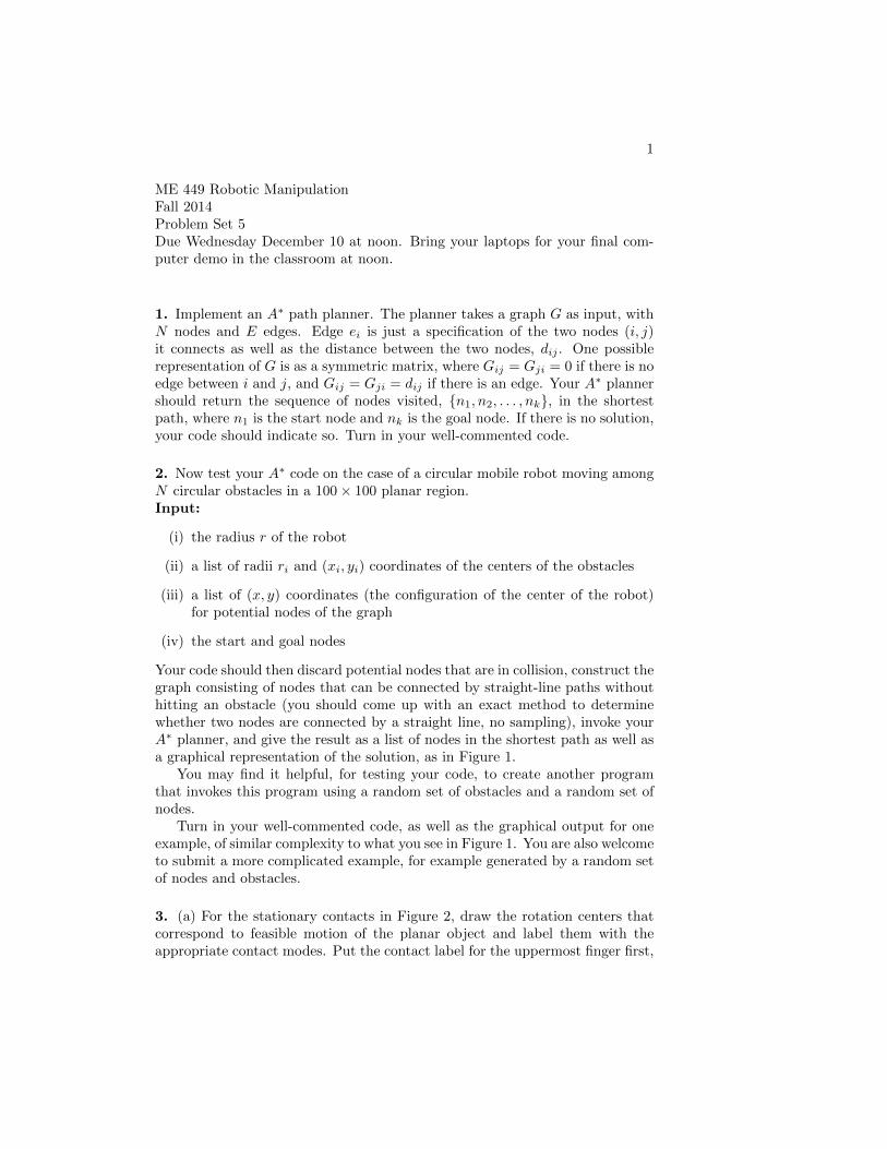
Your code should then discard potential nodes that are in collision, construct thegraph consisting of nodes that can be connected by straight-line paths withouthitting an obstacle (you should come up with an exact method to determinewhether two nodes are connected by a straight line, no sampling), invoke yourA∗ planner, and give the result as a list of nodes in the shortest path as well asa graphical representation of the solution, as in Figure 1.
You may find it helpful, for testing your code, to create another programthat invokes this program using a random set of obstacles and a random set ofnodes.
Turn in your well-commented code, as well as the graphical output for oneexample, of similar complexity to what you see in Figure 1. You are also welcometo submit a more complicated example, for example generated by a random setof nodes and obstacles.
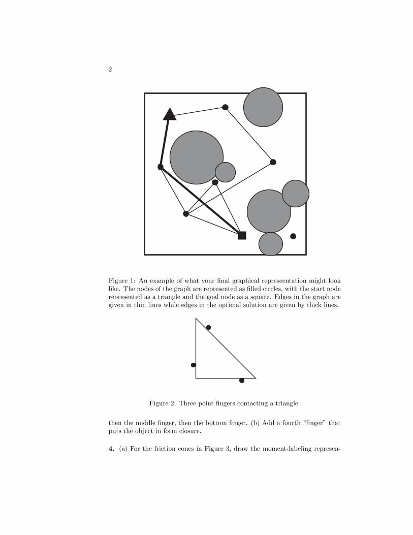
3. (a) For the stationary contacts in Figure 2, draw the rotation centers thatcorrespond to feasible motion of the planar object and label them with theappropriate contact modes. Put the contact label for the uppermost finger first,
2
Figure 1: An example of what your final graphical represeentation might looklike. The nodes of the graph are represented as filled circles, with the start noderepresented as a triangle and the goal node as a square. Edges in the graph aregiven in thin lines while edges in the optimal solution are given by thick lines.
Figure 2: Three point fingers contacting a triangle.
then the middle finger, then the bottom finger. (b) Add a fourth “finger” thatputs the object in form closure.
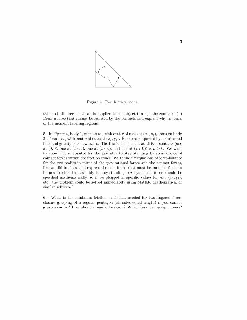
4. (a) For the friction cones in Figure 3, draw the moment-labeling represen-
3
Figure 3: Two friction cones.
tation of all forces that can be applied to the object through the contacts. (b)Draw a force that cannot be resisted by the contacts and explain why in termsof the moment labeling regions.
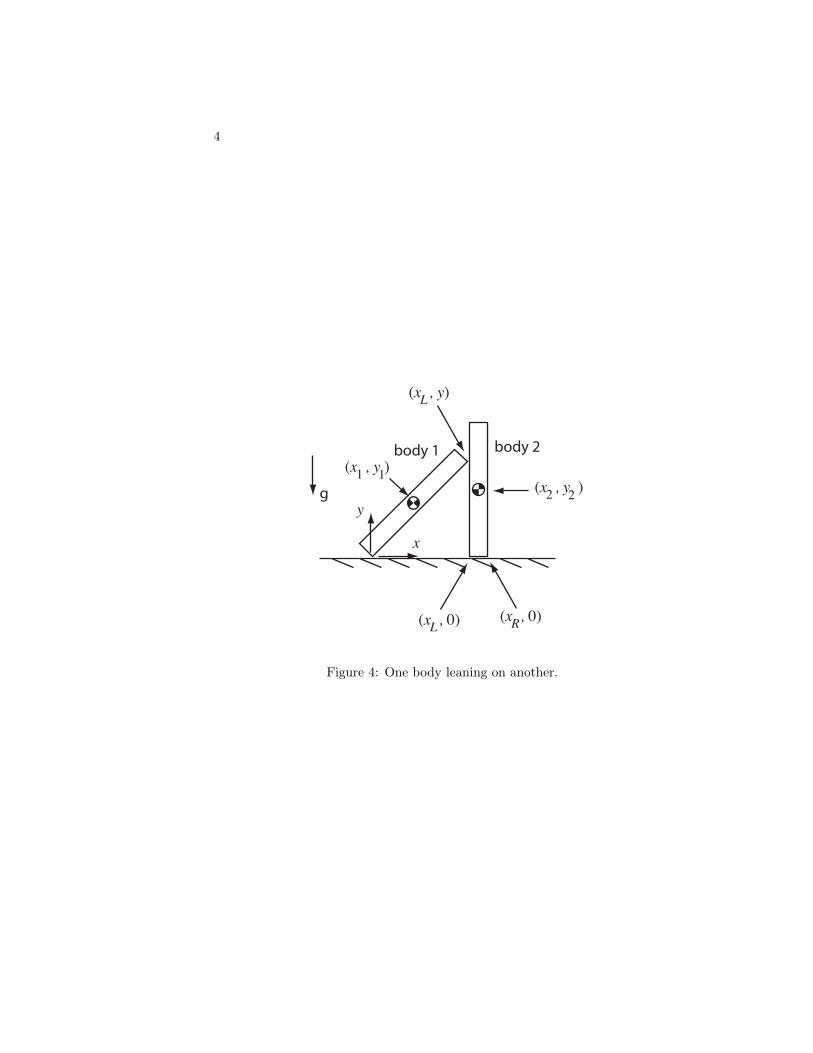
5. In Figure 4, body 1, of mass m1 with center of mass at (x1, y1), leans on body2, of mass m2 with center of mass at (x2, y2). Both are supported by a horizontalline, and gravity acts downward. The friction coefficient at all four contacts (oneat (0, 0), one at (xL, y), one at (xL, 0), and one at (xR, 0)) is µ > 0. We wantto know if it is possible for the assembly to stay standing by some choice ofcontact forces within the friction cones. Write the six equations of force-balancefor the two bodies in terms of the gravitational forces and the contact forces,like we did in class, and express the conditions that must be satisfied for it tobe possible for this assembly to stay standing. (All your conditions should bespecified mathematically, so if we plugged in specific values for m1, (x1, y1),etc., the problem could be solved immediately using Matlab, Mathematica, orsimilar software.)
6. What is the minimum friction coefficient needed for two-fingered force-closure grasping of a regular pentagon (all sides equal length) if you cannotgrasp a corner? How about a regular hexagon? What if you can grasp corners?
4
g
body 1 body 2
x
y
(x , 0)L(x , 0)R
(x , y )1 1(x , y )2 2
(x , y)L
Figure 4: One body leaning on another.