1 an-najah national university mechanical engineering department graduation project 2 drugs addicts...
TRANSCRIPT

1
An-Najah National UniversityMechanical Engineering Department
Graduation Project 2Drugs Addicts Rehabilitation Center
The Students:Ramez Rafeeq Ishtayyeh (10840852) Othman Jaser Irshead (10825361)Amr Mohammad Masri (10718810)Hikmat Reda Hjab (10544696)
Supervisor: Dr. Iyad Assaf.
• The aim of this project is to design installation of heating, ventilation and air condition system (HVAC) for Drugs Addicts Rehabilitation Center.
• Air Conditioning will be used in the building for heating and cooling.
• Water service and plumping design is required for service system inside the building.
• Fire protection system serves to detect the fire and evacuate the building.
2

Presentation outline
- Building Description.
- Heating load calculation.
- Cooling load calculation.
- Duct Design.
- Plumbing System.
- Fire protection System
- Equipment Selection.
3

Building Description Building Location:
Drugs Addicts Rehabilitation Center location in Bait Wazan /Nablus city-Palestine that consist of four floor, two basement floors, ground floor,
and first floor .
Elevation: 700 m above sea level
Latitude: 32˚
Building face sits at the North direction .
The wind speed in Nablus above 5 m/s.
4

Building detailsThe building consists of seven sections: 1.: EntranceConsists of waiting rooms, information center, registration, W.C.2.: Administration DepartmentConsists of director rooms and secretarial, archive, hall meetings, W.C.3.: Diagnosis and evaluationConsists of waiting rooms, rooms for specialists, rooms for doctors, store, W.C.4.: Therapy DepartmentConsists of Music therapy unit, computer therapy unit, physical exercises unit, stores, W.C.
5

5.: Community Service UnitConsists of consulting room, lectures room, hall practical training, conference hall, W.C.6.: Medical treatmentConsists of rooms for doctors, rooms for nurses, lab, store medicines, rooms for examination, W.C.7.: Public ServicesConsists of maintenance room, kitchen, swimming pool, hall to eat, hall activities
6

Heating load
The heat loss is calculated by this equation :
7
Outside design condition
Inside design condition
Parameters
8.3° C 22° C T: temperature
72% 50% Φ : relative humidity
9.4 g of water/kg of dry air
8.4 g of water/kg of dry air
W : moisture content
15.15° C Tun: unconditioned temperature
5° C Tg : ground temperature

Summary for heating loadHeating load (kw) Block
97.1 Block A
281.6 Block B
109.2 Block C
487.9) kw( Total
8

Cooling LoadOutside design condition Inside design condition Parameters
33.7 °C 24 °C T: temperature
44% 50% Φ : relative humidity
12.5 g of water/kg of dry air 9.4 g of water/kg of dry air W : moisture content
30.5°C Tun: unconditioned temperature
5 °C Tg : ground temperature
9
The general conduction equation in cooling calculation is:
For transmitted through glass:
For convection through glass:

Summary of cooling load
Cooling load (ton ref) Block
61 Block A
256.1 Block B
53.7 Block C
352.8) ton ref( Total
10

Duct Design Design procedures
*The total sensible heat was calculated.
* The Vcirculation was calculated.
* The flow rate (CFM) was calculated .
* Number of diffusers are calculated and distributed uniformly.
* The initial velocity for the main duct is 5 m/s.
* The pressure drop is depend on the initial velocity for the main
duct and flow rate (CFM) .
* The main diameter is calculated .
* The height and width of the rectangular ducts are determined from the tables.
11

Sample calculation For duct Design:
12

1313

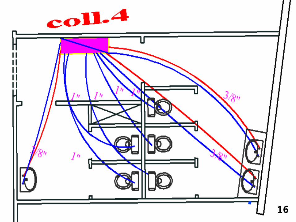
Plumbing System
Total demand water:
14
Demand Water (L/S)
Totally Fixture Unit
Type Of Supply Water
13.67 1070.75 Cold
6.81 300.75 Hot

1515
16

17

Fire Protection System The Class III is used for design the fire system
Pipe size
18
Size (in) Demand(GPM) Name of pipe
4’’ 1000 Main pipe
4’’ 250 Riser for block A
4’’ 500 Riser for block B
4’’ 250 Riser for block C
2 1/2’’ 250 Pipe for landing valve
1 1/2’’ 100 Pipe for Cabinet

19

20

Equipment Selection
Selection of component in mechanical system is the final stage in this building design because it depends on the all previous system design
21
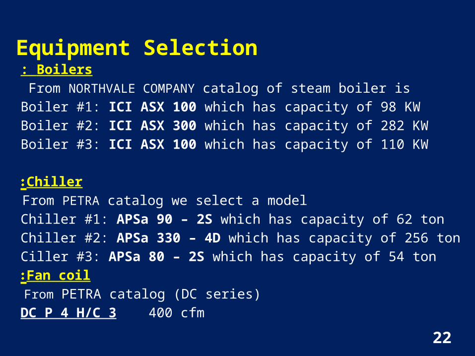
Equipment SelectionBoilers:
From NORTHVALE COMPANY catalog of steam boiler is
Boiler #1: ICI ASX 100 which has capacity of 98 KW
Boiler #2: ICI ASX 300 which has capacity of 282 KW
Boiler #3: ICI ASX 100 which has capacity of 110 KW
Chiller:
From PETRA catalog we select a model
Chiller #1: APSa 90 – 2S which has capacity of 62 ton
Chiller #2: APSa 330 – 4D which has capacity of 256 ton
Ciller #3: APSa 80 – 2S which has capacity of 54 ton
Fan coil:
From PETRA catalog (DC series)
DC P 4 H/C 3 400 cfm 22

Equipment selection cont.
23
Fresh air and Exhaust fans:
From EASY VENT – SNP company
The selection of fresh air fans for the building were done as the following: Fan#1 CFM = 6500
Static pressure=22 mm.H2O
Model : CVTT-12/12
Fan#2 CFM = 7100
Static pressure=29 mm.H2O
Model : CVTT-12/12
Fan#3 CFM = 7500
Static pressure=33 mm.H2O
Model : CVTT-12/12

Equipment selection cont . Pumps
Chiller pump for Block(B):
Flow rate = 32 m3/hr ΔP = 14m
Model: CM25-1 60 Hz
Chiller pump for Block(A&C):
Flow rate = 20 m3/hr ΔP = 9m
Model: 96411834 TP 80-160/2 B 60 Hz`
Boiler pump for Block(B):
Flow rate = 35 m3/hr ΔP =14 m
Model: CME25-1 60 Hz 24

Boiler pump for Block(A&C) :
Flow rate =26 m3/hr ΔP =9m
Model: 96411834 TP 80-160/2 B 60 Hz
Electrical and diesel Fire-Fighting Pump
Flow rate = 1000 GPM ΔP =129.0948 psi
Model: 5-491-18 A
Standby Pump ( Jockey Pump )
Flow rate = 20 GPM ΔP =142 psi
Model: 2-383-9C25

SUMMARY
*All steps of design and plans of HVAC system are done .
*All steps of design and plans of plumping system are done.
*we select a suitable equipment for the system which satisfied the required conditions.
26

Thank you
27