1 basics of fire and explosion: risk assessment · however, when this experiment is repeated after...
TRANSCRIPT

1
Static Electricity: Understanding, Controlling, Applying, First Edition.Günter Lüttgens, Sylvia Lüttgens, and Wolfgang Schubert.© 2017 Wiley-VCH Verlag GmbH & Co. KGaA. Published 2017 by Wiley-VCH Verlag GmbH & Co. KGaA.
1
If static electricity was really static, as one may assume by its name, then it could be ignored. Only when it becomes more dynamic does it appear to be interesting and extend in our awareness from harmless electric shocks, sometimes felt when leaving a car, to the possibly fatal lightning strokes of a thunderstorm (for the latter, there is detailed information given in www. lightningsafety.noaa.gov).
However, our intention in this book is to demonstrate that the obviously weak electrostatic discharges are more or less capable of igniting combustible materi-als, thus causing hostile fire and casualties. It is probably because of its unpre-dictability that static electricity is often incorrectly blamed as a cause of fire and explosion when no other plausible explanation is at hand. So it seems logical to start with basics on fire and explosion.
1.1 Basic Considerations on Fire and Explosion ( T1)
In which way do fire and explosion differ from one another?Common to both is the manifestation of a flame, which always indicates a fast
combustion of fuel/air mixtures in the gaseous phase. The chemical reac-tion, depending on the combustion heat of the fuel, leads to an increase in temperature.
Fire is characterized mainly by a stationary burning flame in an open atmos-phere, for example, a lighted candle. Therefore the reaction heat spreads into the surroundings without increase in pressure.
However, when an ignition occurs in a combustible atmosphere within an enclosed space, for example, a drum, a flame front runs through the entire space, starting from the ignition source. Under atmospheric conditions, the flame front extends at a speed of 10 m/s. Therefore the heating effect of the flame causes a pressure increase of about 10 bars, which diminishes during subsequent cooling. It is decisive that this short time pressure increase may cause a devastating dam-age called explosion.
The exothermic reaction of fuel in air occurs between the tiniest particles, that is, the molecules of fuel and oxygen. This is the case when prevailing fuel gas forms the required gaseous phase. With flammable liquids, this molecular fuel/oxygen
Basics of Fire and Explosion: Risk Assessment
c01.indd 1 8/8/2017 7:08:10 PM
1 Basics of Fire and Explosion: Risk Assessment2
mixture can easily be achieved by vaporization of the liquid. However, for solid fuels (dusts, but not metal dusts), it is necessary to break their chemical bonds so that hydrocarbon molecules are set free to react with oxygen. Therefore a consid-erable part of the ignition energy is used for melting, vaporizing, or cracking the dust particles to gaseous hydrocarbons. This is the reason why much more energy is always needed to ignite flammable dusts than is necessary to ignite flammable gases and vapors.
On the contrary, at metal dusts an oxidization at the particle surface takes place, which is exothermic as well.
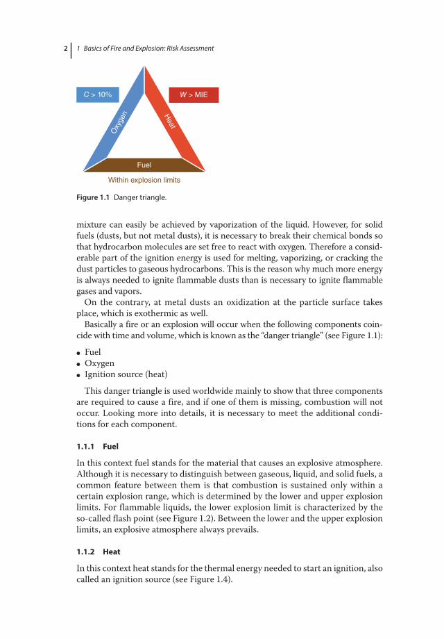
Basically a fire or an explosion will occur when the following components coin-cide with time and volume, which is known as the “danger triangle” (see Figure 1.1):
● Fuel ● Oxygen ● Ignition source (heat)
This danger triangle is used worldwide mainly to show that three components are required to cause a fire, and if one of them is missing, combustion will not occur. Looking more into details, it is necessary to meet the additional condi-tions for each component.
1.1.1 Fuel
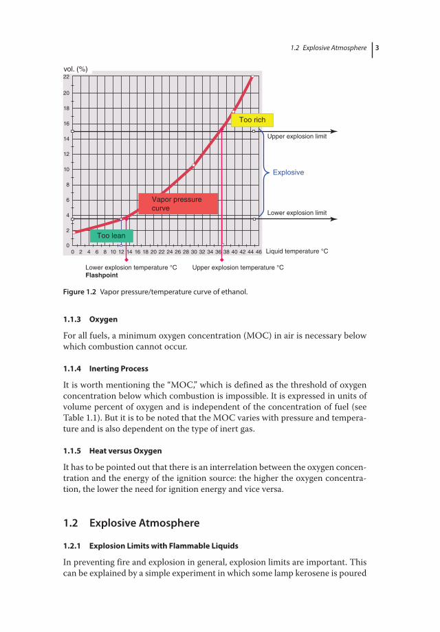
In this context fuel stands for the material that causes an explosive atmosphere. Although it is necessary to distinguish between gaseous, liquid, and solid fuels, a common feature between them is that combustion is sustained only within a certain explosion range, which is determined by the lower and upper explosion limits. For flammable liquids, the lower explosion limit is characterized by the so-called flash point (see Figure 1.2). Between the lower and the upper explosion limits, an explosive atmosphere always prevails.
1.1.2 Heat
In this context heat stands for the thermal energy needed to start an ignition, also called an ignition source (see Figure 1.4).
Fuel
Oxy
gen H
eat
W > MIEC > 10%
Within explosion limits
Figure 1.1 Danger triangle.
c01.indd 2 8/8/2017 7:08:10 PM
1.2 Explosiie Atmosppere 3
1.1.3 Oxygen
For all fuels, a minimum oxygen concentration (MOC) in air is necessary below which combustion cannot occur.
1.1.4 Inerting Process
It is worth mentioning the “MOC,” which is defined as the threshold of oxygen concentration below which combustion is impossible. It is expressed in units of volume percent of oxygen and is independent of the concentration of fuel (see Table 1.1). But it is to be noted that the MOC varies with pressure and tempera-ture and is also dependent on the type of inert gas.
1.1.5 Heat versus Oxygen
It has to be pointed out that there is an interrelation between the oxygen concen-tration and the energy of the ignition source: the higher the oxygen concentra-tion, the lower the need for ignition energy and vice versa.
1.2 Explosive Atmosphere
1.2.1 Explosion Limits with Flammable Liquids
In preventing fire and explosion in general, explosion limits are important. This can be explained by a simple experiment in which some lamp kerosene is poured
vol. (%)22
20
18
16
14
12
10
8
6
4
2
00 2 4 6 8 10 12 14 16 18 20 22 24 26 28 30 32 34 36 38 40 42 44 46
Upper explosion limit
Too rich
Vapor pressurecurve
Lower explosion limit
Liquid temperature °C
Upper explosion temperature °CLower explosion temperature °CFlashpoint
Explosive
Too lean
Figure 1.2 Vapor pressure/temperature curve of ethanol.
c01.indd 3 8/8/2017 7:08:10 PM

1 Basics of Fire and Explosion: Risk Assessment4
into a small coquille: when a lighted match is dipped into the liquid, it becomes extinguished. Obviously lamp kerosene is fuel!
However, when this experiment is repeated after the lamp kerosene is heated up to 45 °C, the lighted match causes an ignition, and the liquid continues to burn at its surface.
The explanation for the behavior of the lamp kerosene in the aforementioned experiment has to do with the vapor pressure of the liquid. Depending on the temperature of the liquid, a certain vapor pressure, and hence vapor concentration, is developed above the surface of the liquid. Figure 1.2 shows the vapor pressure temperature curve for ethanol and the relation between the vapor concentration at the surface of the liquid and its temperature. As ethanol is indicated by a flash point of 12°C the above mentioned experiment would lead to a flame already at room temperature.
By using the curve, temperatures can be assigned to the lower and upper explosion limits of a liquid. The temperature related to the lower explosion limit is called the flash point (°C) and is a simple and reliable way of defining the danger of flammable liquids in view of their ease of ignition. Liquids at a tem-perature lower than their flash point cannot be ignited. Therefore, the flash point ranks as the most important data when using flammable liquids and is listed in safety data sheets, for instance, indicating that they will not burn at room temperature.
In the example for ethanol, the explosion danger exists only within the explo-sion range, which is limited by the lower explosion temperature (12 °C) and the upper one (37 °C). After ignition, the flame spreads through the entire volume without any further fuel or air access. Also, it has to be taken into consideration
Table 1.1 Threshold of oxygen concentration for some gases and dusts with two kinds of inert gases (volume percent oxygen).
Gas or dust Nitrogen/air Carbon dioxide/air
Ethane 11 14Hydrogen 5 5Isobutane 12 15Methane 12 15n-Butane 12 15Propane 12 15PE-HD 16 —PE-LD 16 —Paper 14 —PMMA 16 —PP 16 —PVC 17 —
c01.indd 4 8/8/2017 7:08:10 PM
1.2 Explosiie Atmosppere 5
that ignition is not possible above the upper explosion temperature. The fuel/air mixture is, so to speak, too rich, because of a lack of oxygen. This effect is used, for example, in gasoline tanks for cars. They will never explode but may burn down when there is a leakage (access to air).
Below the lower explosion limit, the average distance between fuel molecules to each other in air is too large; hence, by means of radiation from the ignition source, no sufficient energy can be transferred to continue the ignition (the decrease of energy by radiation follows the square of the distance). Above the upper explosion limit, the concentration of fuel molecules is so high that there is no enough oxygen between them for a reaction to take place.
In this context, it has to be stated that all vapors of flammable liquids show a higher density than air; thus they will always accumulate at the bottom of a vessel.
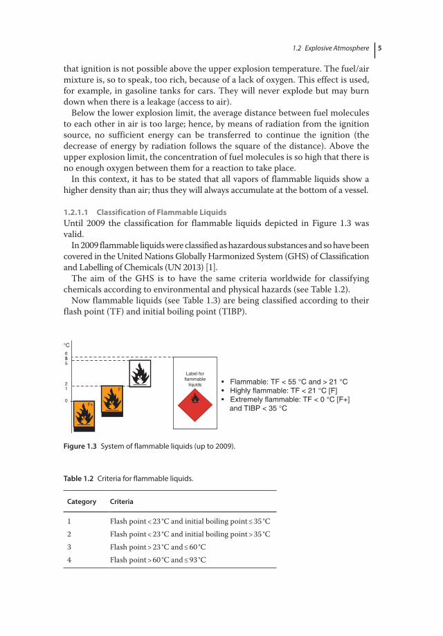
1.2.1.1 Classification of Flammable LiquidsUntil 2009 the classification for flammable liquids depicted in Figure 1.3 was valid.
In 2009 flammable liquids were classified as hazardous substances and so have been covered in the United Nations Globally Harmonized System (GHS) of Classification and Labelling of Chemicals (UN 2013) [1].
The aim of the GHS is to have the same criteria worldwide for classifying chemicals according to environmental and physical hazards (see Table 1.2).
Now flammable liquids (see Table 1.3) are being classified according to their flash point (TF) and initial boiling point (TIBP).
°C6
F
F+
5
21
0
Label forflammable
liquids • Flammable: TF < 55 °C and > 21 °C• Highly flammable: TF < 21 °C [F]• Extremely flammable: TF < 0 °C [F+] and TIBP < 35 °C
53
Figure 1.3 System of flammable liquids (up to 2009).
Table 1.2 Criteria for flammable liquids.
Category Criteria
1 Flash point < 23 °C and initial boiling point ≤ 35 °C2 Flash point < 23 °C and initial boiling point > 35 °C3 Flash point > 23 °C and ≤ 60 °C4 Flash point > 60 °C and ≤ 93 °C
c01.indd 5 8/8/2017 7:08:11 PM

1 Basics of Fire and Explosion: Risk Assessment6
Table 1.3 Flammable liquids, classification, and labeling.
Hazard category
Pictogram Signal word Hazard statement Hazard statement codes
1 Danger Extremely flammable liquid and vapor
H224
2 Danger Highly flammable liquid and vapor
H225
3 Warning Flammable liquid and vapor H226
4 No pictogram
Warning Combustible liquid H227
Note: Aerosols should not be classified as flammable liquids.
1.2.2 Explosion Limits with Combustible Dusts
In contrast to gases and vapors, mixtures of solid fuels (combustible dusts) and air are inhomogeneous because of the effect of gravity on particles; for example, with dusts in air, the particle distribution is not constant with reference to time and space. In terms of safety, the explosion limits for dust/air mixtures are not as critical as those for vapor/air and gaseous/air mixtures.
For most combustible organic dusts, the lower explosion limit ranges between 20 and 50 g/m3. However, there are a few very sensitive dusts with a lower explo-sion limit down to 10 g/m3. For instance, a few millimeters of combustible dust settled on the floor may present an explosion hazard in the entire room when swirled up by a draft of air. To determine an upper explosion limit is difficult as it ranges in concentrations of 1 kg/m3 and above.
1.2.3 Metal Dusts
Finely dispersed airborne metallic dust can also be explosive in so far as the metal itself tends to oxidize.
In contrast to the aforementioned organic dusts, transfer into the gaseous phase is not necessary to ignite metal dusts because they react exothermally directly at their surfaces with the oxygen in air.
1.3 Hybrid Mixtures ( P7)
An increased ignition danger always exists when powder products are combined with combustible gases or vapors because the ignition energy of the latter is lower on most occasions. Furthermore it has to be taken into consideration that hybrid mixtures are already combustible when the concentration of the dust as
c01.indd 6 8/8/2017 7:08:11 PM

1.5 ermissiile EEqipment EEqipment rotection eiell 7
well as that of the gas is lower than their respective explosion limits. The needed energy to ignite hybrid mixtures is always lower than that of the pure dust cloud. Hybrid mixtures are to be expected, for example, when the powder is wet with flammable solvents.
1.4 Allocation of Explosion-Endangered Areas and Permissible Equipment ( P6)
In the ATEX 137 “Workplace Directive,” the minimum requirements for improv-ing the safety of workers potentially at risk from explosive atmospheres are laid down.
The plant management must divide areas where hazardous explosive atmos-pheres may occur into “zones.” The classification given to a particular zone and its size and location depends on the likelihood of an explosive atmosphere occur-ring and its persistence if it does.
An explosive atmosphere can be divided into zones according to IEC 60079-10-1 and 60079-10-2 [2]:
Zone 0: Area in which an explosive atmosphere consisting of a mixture with air of flammable substances in the form of gas, vapor, or mist is present continu-ously or for long periods or frequently
Zone 1: Area in which an explosive atmosphere consisting of a mixture with air of flammable substances in the form of gas, vapor, or mist is likely to occur in normal operation occasionally
Zone 2: Area in which an explosive atmosphere consisting of a mixture with air of flammable substances in the form of gas, vapor, or mist is not likely to occur in normal operation but, if it does occur, will persist for a short period only
Zone 20: Area in which an explosive atmosphere in the form of a cloud of com-bustible dust in air is present continuously or for long periods or frequently for short periodsNote: Areas where piles of dust are present but where dust clouds are not present continuously, or for a long period, or frequently are not included in this zone.
Zone 21: Area in which an explosive atmosphere in the form of a cloud of com-bustible dust in air is likely to occur occasionally in normal operation
Zone 22: Area in which an explosive atmosphere in the form of a cloud of com-bustible dust in air is not likely to occur in normal operation but if it does occur will persist for a short period only
1.5 Permissible Equipment (Equipment Protection Level)
An equipment category indicates the level of protection provided by the equip-ment to be used according to zones ( T6).
Here, areas in which an explosive atmosphere consisting of a mixture with air of flammable substances in the form of gas, vapor, or mist prevails are indicated
c01.indd 7 8/8/2017 7:08:11 PM
1 Basics of Fire and Explosion: Risk Assessment8
with the letter G (gas). Correspondingly, areas in which an explosive atmosphere in the form of a cloud of combustible dust in air exists are indicated with the let-ter D (dust).
1.5.1 Classification of Equipment Protection Level That Is Currently in the Introductory Stage
As already discussed, explosive atmospheres are divided into zones based on the probability that such an atmosphere will occur. But experience has shown that in some situations, a risk assessment would give the plant operator more flexibility. On this account and to facilitate a dependable risk assessment approach to make equipment selection easier, “equipment protection levels” (EPLs) have been introduced. EPLs identify and characterize all equipments according to the igni-tion risk they might produce.
According to IEC60079-0:2011 [3], equipment for use in explosive atmos-pheres is classified into the following EPLs (with distinguishing signs such as M for mining, G for gases, and D for dusts).
EPL Ma: Equipment for installation in a mine susceptible to firedamp, having a “very high” level of protection, which has sufficient security that it is unlikely to become an ignition source in normal operation, during expected malfunc-tions, or during rare malfunctions, even when left energized in the presence of an outbreak of gas
EPL Mb: Equipment for installation in a mine susceptible to firedamp, having a “high” level of protection, which has sufficient security that it is unlikely to become a source of ignition in normal operation or during expected malfunc-tions in the time span between there being an outbreak of gas and the equip-ment being de-energized
EPL Ga: Equipment for explosive gas atmospheres, having a “very high” level of protection, which is not a source of ignition in normal operation, during expected malfunctions, or during rare malfunctions
EPL Gb: Equipment for explosive gas atmospheres, having a “high” level of pro-tection, which is not a source of ignition in normal operation or during expected malfunctions
EPL Gc: Equipment for explosive gas atmospheres, having an “enhanced” level of protection, which is not a source of ignition in normal operation and which may have some additional protection to ensure that it remains inactive as an ignition source in the case of regular expected occurrences
EPL Da: Equipment for explosive dust atmospheres, having a “very high” level of protection, which is not a source of ignition in normal operation, during expected malfunctions, or during rare malfunctions
EPL Db: Equipment for explosive dust atmospheres, having a “high” level of pro-tection, which is not a source of ignition in normal operation or during expected malfunctions
EPL Dc: Equipment for explosive dust atmospheres, having an “enhanced” level of protection, which is not a source of ignition in normal operation and which may have some additional protection to ensure that it remains inactive as an ignition source in the case of regular expected occurrences
c01.indd 8 8/8/2017 7:08:11 PM

1.6 Inition oqrces 9
It can be expected that in the future EPL will take the place of zones. Table 1.4 shows the relationship between zone, category, and EPL.
1.6 Ignition Sources
Ignition sources are, according to scientific knowledge and experience, the means of releasing energy that is capable of igniting certain combustible mate-rials when mixed with air. In the early 1960s, the evaluation of innumerable fire and explosion events had already shown that there were only 13 different ignition sources to be considered. Since then, various experts have experi-mented with ignition sources but have found it impossible either to reduce the number by combining ignition sources of the same nature or to find new ones. Today, 50 years later, the efforts of many experts throughout the world con-firm that there are, indeed, only 13 ignition sources to deal with. They are listed in the following with short practical examples. However, it should be noted that it does not rank the ignition sources according to their frequency of occurrence.
1.6.1 Hot Surfaces
Hot surfaces arise as a result of energy losses from systems, equipment, and com-ponents during normal operation. In the event of a malfunction, the temperature may increase. Examples include coils, resistors, or lamps, hot equipment sur-faces, brakes, or overheating bearings.
1.6.2 Flames and Hot Gases (Including Hot Particles)
Flames and hot gases including hot particles can occur inside combustion engines devices during normal operation and outside when a fault has taken place. Protective measures are required, for example, exhaust cooling devices.
Examples include autogenous welding and exhausts from internal combustion engines or particles, which are caused by switching sparks of electrical power lines.
Table 1.4 Relationship between zone, category, and EPL.
Zone Category EPL
0 1G Ga1 2G Gb2 3G Gc20 1 D Da21 2 D Db22 3 D Dc
c01.indd 9 8/8/2017 7:08:11 PM
1 Basics of Fire and Explosion: Risk Assessment10
1.6.3 Mechanically Generated Sparks ( MGS)
Mechanically generated sparks (MGS) come into being during grating, striking, and grinding actions when particles are cut off from solid materials. Due to the energy used for the separating process, particles will have a higher temperature. If these particles consist of oxidizable material (e.g., iron), they may reach tem-peratures up to 1000 °C on their flight path caused by the reaction with atmos-pheric oxygen, thus becoming sparks. MGS are capable of igniting flammable gases and dust atmospheres.
1.6.4 Electrical Apparatus
In general electrical apparatus are regarded as an ignition source. Exceptions are electrical devices containing only intrinsically safe circuits.
1.6.5 Cathodic Protection
Cathodic protection is an efficient and durable corrosion protection of metal equipment. Therefore it has to be taken into account that the used earthed voltage suppliers can result in stray electric currents, which then may bring up potential differences between different earthing points, possibly causing electric sparks.
1.6.6 Static Electricity
Static electricity is an ignition source that is often neglected, therefore making it the topic of this book.
1.6.7 Lightning
The impact of lightning can result in the ignition of an explosive atmosphere. However, there is also a possibility of ignition due to the high temperature reached by lightning conductors. Large currents flowing from lightning strikes, for example, via a lightning conductor, can produce an induction voltage into conductors in the vicinity of the point of impact, thus causing electrical sparks.
1.6.8 Electromagnetic Field
Electromagnetic waves have high frequency ranging from 104 Hz to 3 × 10¹¹ Hz. Examples include transmitting and receiving equipment and mobile telephones.
1.6.9 Electromagnetic Radiation
Electromagnetic radiation is a form of energy that includes infrared radiation, visible light, and many more. Examples include photoflash, laser, and lamp for night vision devices.
1.6.10 Ionizing Radiation
Examples of ionizing radiation include X-rays for material testing and UV rays for radiation-induced polymerization.
c01.indd 10 8/8/2017 7:08:11 PM

1.7 inimqm Inition EnerIgy El 11
1.6.11 Ultrasonics
Examples of ultrasonics include ultrasonic material testing and ultrasonic clean-ing equipment.
1.6.12 Adiabatic Compression and Shock Waves
Examples of adiabatic compression and shock waves include starting a compres-sor in opposite direction and drift waves in long pipes.
1.6.13 Chemical Reactions
Examples of chemical reactions include exothermic processes.
Concerning the ignitability of ignition sources, there are some that are capable of igniting all combustible materials (e.g., flames, lightning stroke). However, it is different in hot surfaces, mechanical sparks, and static electricity. These can only ignite certain combustible materials, depending on particular parameters, such as the ignition temperature and the minimum ignition energy (MIE) of the mate-rial (see Table 1.5).
1.7 Minimum Ignition Energy (MIE)
The MIE of an optimum mixture of a combustible material with air (or oxygen) is defined as the smallest amount of energy needed to cause the ignition of the mix-ture when measured by a standard method. It is a means of classifying hazardous situations where fires and explosions might be initiated. The energy can be sup-plied in a number of ways but is directly quantifiable only when delivered in the form of a capacitive spark discharge.
The definition of MIE given earlier takes no account of the spatial and tempo-ral distribution of the energy. The conversion of a given amount of electrostatic spark energy into heat could occur in a large volume and/or over a long period of time. Without doubt, such conditions would be far less favorable for the promo-tion of an ignition than if the same energy was released into a tiny volume over a short period of time. Furthermore a complication is that not all of the energy released by the capacitor in a spark is converted into thermal energy. Some of the energy is lost as heat in the wiring of the discharge circuit and to the electrodes across which the spark passes; some is lost in the form of light and electromag-netic radiation and some by the pressure exerted by the spark. Also, there is always a small residual charge left on the capacitor after the discharge. Thus, the determination of MIE is, intrinsically, prone to error, and so the measurement of precise values is not possible.
Table 1.5 Classification of combustible gases into temperature classes.
Temperature class T1 T2 T3 T4 T5 T6Ignition temperature >450 °C >300 °C >200 °C >135 °C >100 °C >85 °C
c01.indd 11 8/8/2017 7:08:11 PM

1 Basics of Fire and Explosion: Risk Assessment12
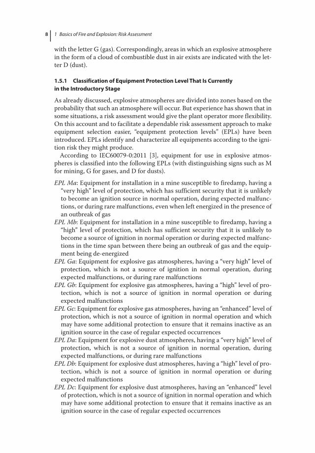
For an ignition to occur, the concentration of the combustible material (gas, vapor, or dust) in the mixture must lie between an upper and a lower flammability limit. For concentrations above the upper limit, there is insufficient oxygen to support and propagate combustion, while for those below the lower limit, there is insufficient fuel for combustion. A plot of ignition energy against the concentra-tion of the fuel in a fuel/air mixture is typically a U-shaped curve on which the lowest point denotes the MIE of the mixture (see Figure 1.4). For gases (and vapors), the concentration is measured in terms of the volume of gas in the gas/air mixture, in percent.
Mixtures on either side of the stoichiometric value 1 require more energy to be ignited. Knowing the chemical equation for the reaction between a combustible gas and oxygen, the volume concentration of the gas in the gas/air mixture can be calculated for a stoichiometric mixture (stoichiometric ratio = 1, which is the same as λ = 1).
However, in practice, it is often the case that the most sensitive concentration of the fuel gas is shifted away a little from the stoichiometric mixture during ignition. This arises because of the different rates of diffusion of the gas and oxygen, depending on their relative molecular weights, into the zone of the mixture, which
3
2.8
2.6
2.4
2.2
2
1.8
1.6
1.4
1.2
1
0.8
0.6
0.4
0.2
0
0.4 0.6 0.8 1 1.2 1.4 1.6 1.8 2 2.2 2.4
Stoichiometric ratio λ
MIE
Toorich
Toolean
mJ
Flammable range
Figure 1.4 Minimum ignition energy subject to the stoichiometric ratio.
c01.indd 12 8/8/2017 7:08:12 PM

1.7 inimqm Inition EnerIgy El 13
is about to be burnt. In the case of propane where the rate of diffusion of the gas is lower than that of the oxygen, because of its higher molecular weight, the mix-ture in the pre-burnt zone is lean in gas. For gases showing a higher density than air (e.g., propane), the MIE occurs slightly above the stoichiometric concentra-tion, and for gases with lower density (e.g., methane), it occurs slightly below.
Referring to the title of this book, some indications are given to electrostatic ignition dangers:
The energies emitted by spark discharges or brush discharges in general are limited to values below 0.5 mJ (see Sections 4.3.1 and 4.3.2.2). This means that electrostatic ignitions actually will occur only with combustible gas/air mixtures in a stoichiometric ratio synonymously with λ = 1.
Assuming that handling of flammable liquids, for example, filling and empty-ing of containers, is usually performed at room temperature, those liquids that form a mixture of λ = 1 at their surfaces are at particular risk. Figure 1.5 illustrates this correlation for some selected flammable liquids.
As the flash point depends on the vapor pressure of the liquid, it has been empirically determined that liquids with flash points of approximately 5 °C show a mixture ratio of λ = 1 at their surfaces when approaching temperatures of 20 °C.
This also shows whether toluene in confirmed electrostatic ignitions is affected to an above average degree.
A brief remark on the ignition sensitivity of gases and vapors in correlation with explosion groups:
As already pointed out, mists and dusts to be ignited need much higher amounts of energy than those needed for gases and vapors. The energy needed to ignite the most ignitable mixture of fuel (gas or dust) and oxygen under atmospheric conditions
20
15
10
5
0
–5
–10
–15
–20Acetone
Vinyl acetateBenzene
Ethyl acetate, heptane
Toluene, dichlorethylenePropyle acetate
MIBKEthanolMethanol
Too lean
Form a mixture ratioof λ = 1 at ~20 °C
Too rich
Fla
shpo
int (
°C)
Figure 1.5 Correlation between flash point and λ − 1 – condition.
c01.indd 13 8/8/2017 7:08:12 PM

1 Basics of Fire and Explosion: Risk Assessment14
Table 1.6 Classification of combustible gases into explosion groups.
Explosion group
Substance
I (mining) MethaneIIAMIE ≥ 0.2 mJ
AmmoniaAcetonePropaneBenzene
Cyclohexanen-Butanen-Hexane
GasolineKeroseneHeating oil
Acetaldehyde
IIBMIE < 0.2 mJMIE > 0.02 mJ
Town gasAcrylonitrile
EthanolEthyleneEthylene oxide
Ethylene glycolHydrogen sulfide
Ethyl ether
IICMIE ≤ 0.02 mJ
Hydrogen Acetylene — — Carbon disulfide
Explanation:Group I concerning only mines.Group II concerning all other areas.Group IIA concerning normal incendiary gases.Group IIB concerning highly incendiary gases.Group IIC concerning very highly incendiary gases.
is defined as MIE. For gases, it is substance specific; for dusts, however, it depends decisively on the size of the particles.
The MIE values for gases are already known to a large extent (see Table 1.9 in Section 1.8). According to IEC 60079-0:2011 [3], they are listed in explo-sion groups (see Table 1.6) that are recognized internationally by now (CENELEC – IEC – NEC 505).
With dusts, the classification of ignition dangers is much more complex because besides the influence of the material the size of particles has to be taken into account.
Solid fuels are difficult to be ignited in a compact state, but they are regarded as inflammable. To burst into flames, they first have to be mechanically crushed to have a sufficiently large surface to react with oxygen in air. Therefore the sur-face/mass ratio determines the reaction speed and the ignition sensitivity.
Table 1.7 indicates how crushing of the material brings an enormous increase of surface. By fragmentation a cube of 10 mm side length leads to:
Table 1.7 Increase of surface by fragmentation.
Cubes of Edge length (µm) Surface (m2)
103 1000 →0.006106 100 →0.06109 10 →0.61012 1 →6
c01.indd 14 8/8/2017 7:08:12 PM
1.8 maIinargy Experiment to Assess tpe aaardoqs otential of Flammaile iEqids 15
Analogous to solid fuels in compact state, deposited dusts may burn off, but they are not capable of combustion. Explosion danger arises only when the dust is swirled up, for example, by a propagating brush discharge.
The considerations for mixtures of flammable gases may provide an idea of how complex the relations of combustible dust mixtures are. Although gas mix-tures remain homogeneous when produced, the dusts swirled up in air are not constant in volume and time. In general, the same conditions for the MIE con-cerning the stoichiometric ratio of ~1 apply to gases as well as to dusts.
1.8 Imaginary Experiment to Assess the Hazardous Potential of Flammable Liquids
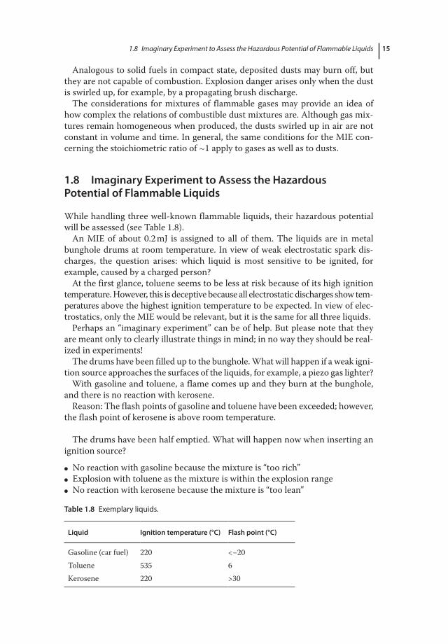
While handling three well-known flammable liquids, their hazardous potential will be assessed (see Table 1.8).
An MIE of about 0.2 mJ is assigned to all of them. The liquids are in metal bunghole drums at room temperature. In view of weak electrostatic spark dis-charges, the question arises: which liquid is most sensitive to be ignited, for example, caused by a charged person?
At the first glance, toluene seems to be less at risk because of its high ignition temperature. However, this is deceptive because all electrostatic discharges show tem-peratures above the highest ignition temperature to be expected. In view of elec-trostatics, only the MIE would be relevant, but it is the same for all three liquids.
Perhaps an “imaginary experiment” can be of help. But please note that they are meant only to clearly illustrate things in mind; in no way they should be real-ized in experiments!
The drums have been filled up to the bunghole. What will happen if a weak igni-tion source approaches the surfaces of the liquids, for example, a piezo gas lighter?
With gasoline and toluene, a flame comes up and they burn at the bunghole, and there is no reaction with kerosene.
Reason: The flash points of gasoline and toluene have been exceeded; however, the flash point of kerosene is above room temperature.
The drums have been half emptied. What will happen now when inserting an ignition source?
● No reaction with gasoline because the mixture is “too rich” ● Explosion with toluene as the mixture is within the explosion range ● No reaction with kerosene because the mixture is “too lean”
Table 1.8 Exemplary liquids.
Liquid Ignition temperature (°C) Flash point (°C)
Gasoline (car fuel) 220 <−20Toluene 535 6Kerosene 220 >30
c01.indd 15 8/8/2017 7:08:12 PM

1 Basics of Fire and Explosion: Risk Assessment16
The drums have been entirely emptied but not cleaned. Where does an igni-tion occur?
● No reaction with gasoline because the mixture still is “too rich” ● Explosion with toluene as the mixture is within the explosion range ● No reaction with kerosene because the mixture is “too lean”
Will an ignition occur after emptying the drums and cleaning them once with water?
● Explosion with gasoline as the mixture is now within the explosion range. ● Possible reaction with toluene, but the mixture could be “too lean.” ● No reaction with kerosene because the mixture is “too lean.”
It follows that at room temperature toluene is most dangerous because an explosive atmosphere always prevails above its surface (stoichiometric propor-tion = 1 at 19 °C).
Gasoline in an enclosed volume (fuel tank) at room temperature is much less dangerous, as the vapors above its surface are always “too rich.”
After the first fuel load of a new car, a rich mixture prevails in the fuel tank; therefore an explosion will never occur. Only at the filler neck a flame will show up as mentioned earlier with the bunghole.
Even if the fuel tank is emptied, there is no explosion danger as the mixture is still too rich. If the vehicle burns, the fuel tank will not explode; however, burst-ing may occur caused by the vapor pressure that develops inside, leading to a tongue of flame.
On the other hand, an emptied gasoline drum rinsed with water creates an enormous danger because now the vapor concentration may reach the explosion range. This has led to painful experiences when working with “cleaned” gasoline drums (grinding, drilling, welding, etc.).
There are no dangers with kerosene at room temperature. This applies to all flammable liquids that are processed at temperatures below their flash point. However, a safety margin below the flash point of at least 5 K with pure solvents and 15 K with solvent mixtures has to be observed. Table 1.9 shows some com-mon substances.
Table 1.9 Minimum ignition energy (MIE) correlating with minimum ignition charge (MIQ) [4].
Substance MIE (mJ) MIQ (nC) Ignition optimum (Vol.−%)
Explosion group according to IEC 60079-20-1
Acetaldehyde 0.38 — — IIAAcetic acid ethyl ester 0.46 120 5.2 IIAAcetone 0.55 127 6.5 IIAAcroleina) 0.13 — — IIBAcrylonitrile 0.16 — 9.0 IIBAllyl chloridea) 0.77 — — IIAAmmonia 14 1500 20 IIA
c01.indd 16 8/8/2017 7:08:12 PM

1.8 maIinargy Experiment to Assess tpe aaardoqs otential of Flammaile iEqids 17
Substance MIE (mJ) MIQ (nC) Ignition optimum (Vol.−%)
Explosion group according to IEC 60079-20-1
Benzene 0.20 45 4.7 IIA1,3-Butadiene 0.13 — 5.2 IIBButane 0.25 60 4.7 IIA2-Butanone 0.27 — 5.3 IIB2-Butyl chloridea) 1.24 — — IIACarbon disulfide 0.009 — 7.8 IICCyclohexane 0.22 — 3.8 IIACyclopropane 0.17 — 6.3 IIB1,2-Dichloroethane 1.0 — 10.5 IIADichloromethane 9300 880 000 18 IIADiethyl ether 0.19 40 5.1 IIBDiethyl ether in oxygena) 0.0012 — — —b)
2,2-Dimethylbutane 0.25 70 3.4 IIAEthane 0.25 70 6.5 IIAEthanol 0.28 60 6.4 IIBEthylene 0.082 32 8.0 IIBEthylene in oxygena) 0.0009 — — —b)
Ethyne (acetylene) 0.019 — 7.7 IICEthyne in oxygena) 0.0002 — — —b)
Ethylene oxide 0.061 — 10.8 IIBHeptane 0.24 60 3.4 IIAHexane 0.24 60 3.8 IIAHydrogen 0.016 12 22 IICHydrogen in oxygena) 0.0012 — — —b)
Methane 0.28 70 8.5 IIAMethanol 0.20 50 14.7 IIA2-Methylbutane 0.21 63 3.8 IIAMethylcyclohexane 0.27 70 3.5 IIAPentane 0.28 63 3.3 IIAcis-2-Pentene 0.18 — 4.4 IIBtrans-2-Pentene 0.18 — 4.4 IIBPropane 0.25 70 5.2 IIAPropane in oxygena) 0.0021 — — —b)
1-Propyne (methyl acetylene)
0.11 — 6.5 IIB
Propylene oxide 0.13 — 7.5 IIB
Table 1.9 (Continued)
Continqedl
c01.indd 17 8/8/2017 7:08:12 PM
1 Basics of Fire and Explosion: Risk Assessment18
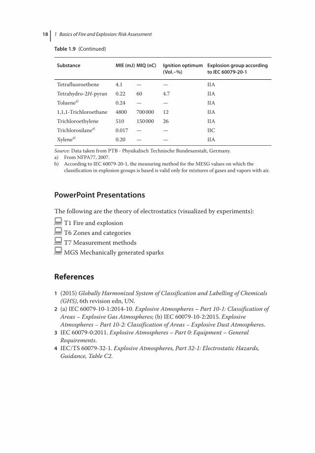
Table 1.9 (Continued)
Substance MIE (mJ) MIQ (nC) Ignition optimum (Vol.−%)
Explosion group according to IEC 60079-20-1
Tetrafluoroethene 4.1 — — IIATetrahydro-2H-pyran 0.22 60 4.7 IIAToluenea) 0.24 — — IIA1,1,1-Trichloroethane 4800 700 000 12 IIATrichloroethylene 510 150 000 26 IIATrichlorosilanea) 0.017 — — IICXylenea) 0.20 — — IIA
Source: Data taken from PTB - Physikalisch Technische Bundesanstalt, Germany.a) From NFPA77, 2007.b) According to IEC 60079-20-1, the measuring method for the MESG values on which the
classification in explosion groups is based is valid only for mixtures of gases and vapors with air.
PowerPoint Presentations
The following are the theory of electrostatics (visualized by experiments):
T1 Fire and explosion T6 Zones and categories T7 Measurement methods MGS Mechanically generated sparks
References
1 (2015) Globally Harmonized System of Classification and Labelling of Chemicals (GHS), 6th revision edn, UN.
2 (a) IEC 60079-10-1:2014-10. Explosive Atmospheres – Part 10-1: Classification of Areas – Explosive Gas Atmospheres; (b) IEC 60079-10-2:2015. Explosive Atmospheres – Part 10-2: Classification of Areas – Explosive Dust Atmospheres.
3 IEC 60079-0:2011. Explosive Atmospheres – Part 0: Equipment – General Requirements.
4 IEC/TS 60079-32-1. Explosive Atmospheres, Part 32-1: Electrostatic Hazards, Guidance, Table C2.
c01.indd 18 8/8/2017 7:08:12 PM