1 bond graph based approach to passive teleoperation of...
TRANSCRIPT

1
Bond graph Based Approach ToPassive Teleoperation Of A Hydraulic Backhoe
Kailash Krishnaswamy and Perry Y. Li
Abstract
Human operated, hydraulic actuated machines are widely used in many high-power applications. Improving productivity, safetyand task quality (eg. haptic feedback in a teleoperated scenario) has been the focus of past research. For robotic systems thatinteract with the physical environments, passivity is a useful property for ensuring safety and interaction stability. While passivityis a well utilized concept in electromechanical robotic systems, investigationof electrohydraulic control systems that enforce thispassivity property are rare. This paper proposes and experimentallydemonstrates a teleoperation control algorithm that rendersa hydraulic backhoe / force feedback joystick system as a two-port, coordinated, passive machine. By fully accounting for thefluid compressibility, inertia dynamics and nonlinearity, coordination performance is much improved over a previous scheme inwhich the coordination control approximates the hydraulic system by its kinematic behavior. This is accomplished by a novelbond graph based three step design methodology: 1) energetically invariant transformation of the system into a pair of “shape”and “locked” subsystems; 2) inversion of the “shape” system bond graph to derive the coordination control law; 3) use of the“locked” system bond graph to derive an appropriate control law to achieve a target “locked” system dynamics while ensuring thepassivity property of the coordinated system. The proposed passivecontrol law has been experimentally verified for its bilateralenergy transfer ability and performance enhancements.
I. I NTRODUCTION
A dynamic system with inputu(t) and outputy(t) is said to be passive with respect tos(u(t), y(t)), called the supply rate,if for all u(·) and timeτ > 0, :
−∫ τ
0
s(u(t), y(t))dt ≤ c2.
Whens(u(t), y(t)) is the (scaled) physical power input, a passive system is onefrom which the net (scaled) energy that canbe extracted is finite, i.e. passive system only stores and dissipates energy but cannot generate energy of its own. Passivesystems are easier and safer for humans to control and they interact with arbitrary passive systems, including many physicalobjects, stably [1]. The inherent safety that passive systems provide has been exploited by researchers in the development ofhuman interacting machines like smart exercise machines [2], passive bilateral teleoperators [3], [4], COBOTS [5] andPTER[6]. While passivity is widely used in electromechanical systems, it is relatively rare in electrohydraulic systems. Our researchin the past few years has been directed toward developing passive hydraulic systems [7], [8], [9], [10], [11]. To enable thepassivity analysis of electrohydraulic systems under closed loop control, methods for enabling single-stage [7], [12] and multi-stage [9] hydraulic valves (through hardware redesign or feedback) to behave like passive two port systems (a command portand a hydraulic port) respect to the total scaled power inputhave been developed. Based on these “passive valves”, bilateralteleoperation control laws for force feedback joysticks and hydraulic actuators [8], [10], and multi-DOF hydraulic machines(such as a backhoe) [11] have been proposed. These control laws render the closed loop controlled hydraulic machine passive,and ensure that the joystick and the hydraulic machine are coordinated.
In our previous approaches to teleoperation of hydraulic machines [8], [10], [11], passivity of the closed loop controlsystemwas always maintained (to ensure safety). However, perfectcoordination between the joystick and the machines was ensuredonly if a kinematic model (i.e. ignoring fluid compressibility and inertial dynamics) of the latter could be assumed. Thisrequirement led to poor coordination performance under certain operating conditions. In the present paper, a bond graph basedpassive teleoperation algorithm design methodology that includes the previously neglected fluid compressibility andinertialeffects is proposed. By utilizing bond graphs’ inherent passivity property, passive control can be designed for systems withcomplex dynamics. Although the approach is applied a hydraulic system here, it should be applicable to other mechatronicsystems as well. The key aspects of the design methodology ispresented in this paper. The readers are referred to [13] forother aspects such as robustness and performance in the presence of uncertainties.
Similar to [3], [4], [14], the system dynamics are first decomposed using an energetically invariant transformation into apair of “shape” and “locked” subsystems that correspond to the coordination and the overall system aspects. The subsystemsare represented in bond graphs so that more complex dynamicscan be handled. Stable coordination control is then derived
Materials based on research supported by the National Science Foundation ENG/CMS-00889640. To appear in the ASME Journal of Dynamic Systems,
Measurement and Control:Special Issue on Novel Robotics and Control. First submitted in March 2005, revised September2005.
K. Krishnaswamy is with the Honeywell Labs, 3660 Technology Dr, Minneapolis, MN 55418, USA. Email:[email protected]
P. Y. Li is with Department of Mechanical Engineering, University of Minnesota, 111 Church St. SE, Minneapolis, MN 55455,USA. Email:[email protected] . Please send all correspondence to him.

2
PC
JOYSTICK
OPERATOR
HUMAN
BAC KHOE
Fig. 1. Teleoperated backhoe consists of a motorized joystick, and a 2-DOF hydraulic backhoe actuated by a set of hydraulic cylinders and proportionalvalves.
by inverting the “shape” system bond graph. An appropriate control law can be derived by comparing the “locked” systembond graph with that of the target “locked” system. Locked system control algorithms that achieve second order and fourthorder target dynamics will be presented. Experimental results demonstrate the bilateral energy transfer ability and performanceenhancements.
The rest of this paper is organized as follows. Section II presents the models of all the subsystems of the teleoperated backhoeand formulates the control design problem. In section III, the bond graph approach to the design of passive teleoperationcontroller is given. Experimental results of the implementation are presented in section IV. Concluding remarks are given insection V.
Notations: Matrices / vectors are bolded, and scalar elements are un-bolded. Superscriptsi = 1, 2 denotes the link number.
II. SYSTEM MODELING AND CONTROL OBJECTIVE
The teleoperated backhoe system is shown in Fig. 1. It consists of a 2-DOF master motorized joystick in a horizontal planeand a 3-DOF Backhoe of which 1-DOF (the boom) is constrained.Backhoe motions are actuated by single-rod hydraulicactuators which are in-turn driven by single-stage proportional valves. Hydraulic power is provided by a pressure compensatedpump operating at constant supply pressurePs. The system models are summarized below with details contained in [13].
A. Single-stage passive valve and Hydraulic actuators
We consider a single stage “passive valve” connected to a single-rod actuator (Fig. 2). The essential step in passifyingasingle stage proportional valve to obtain the “passive valve” is load pressure feedback. Details of this procedure can be foundin [7], [11]. The spool dynamics of the two “passive valves”,which have been experimentally verified are given by:
xv = −Ω1xv + Fx − ΓFL (1)
where xv = [x1v, x2
v]T denotes the valve spool displacements,Fx = [F 1x , F 2
x ]T denotes the passive valve control input,FL = [F 1
L, F 2L]T ; F i
L = AicP
ic − Ai
rPir denotes the differential hydraulic load force,Γ = Diag[γ1, γ2] denotes the load force
gain acting on the spool,Ω1 = Diag[ω11 , ω2
1 ].Consider now the pressure dynamics of the corresponding single rod hydraulic actuators:
β−1VcPc = Qc − Acx,
β−1VrPr = Qr + Arx (2)
whereVc = Diag[V 1c , V 2
c ], Vr = Diag[V 1r , V 2
r ] are the total volumes of the cap and the rod side chamber and hose volumes,β is the fluid compressibility,Pc = [P 1
c , P 2c ], Qc = [Q1
c , Q2c ], Pr = [P 1
r , P 2r ], Qr = [Q1
r, Q2r] are the pressures and flows in

3
3
2
1
4
Ps
0
Pc
Pc
PrPr
FL = AcPc − ArPr
Qc
−Qr
Ac
Ar
x
Fe
xv
Fx
Spool
Supply
Actuator
Return
Fig. 2. Single stage “passive valve” connected to a single-rod actuator
the actuator chambers,Ac = Diag[A1c , A
2c ], Ar = Diag[A1
r, A2r] are the cap and rod side piston cross-section areas andx is
the piston position. SinceV ir andV i
c are dominated by the hose volumes,V ic/r ≈ min(V i
c/r) ≈ max(V ic/r) are assumed to be
constants for both the cap side and rode sides.Using the relationshipsQi
c/Qir = Ai
c/Air and the matched and symmetric properties of the four way directional valve [15],
and by decomposing the valve flows into the no-load flows and a shunt flow components [16]:
Qic = Ai
c(KiQxi
v − KiT (|xi
v|, F iL) · F i
L) (3)
Qir = −Ai
r(KiQxi
v − KiT (|xi
v|, F iL) · F i
L) (4)
where
KiQ(sgn(xi
v)) =Ki
q√
(Aic)
3 + (Air)
3
√
AsPs (5)
KiT (|xi
v|, F iL) =
KiQ|xi
v|√AsPs
√
AsPs − sign(xiv)F i
L
(6)
As(sgn(xiv)) =
Aic, xi
v ≥ 0
Air, xi
v < 0(7)
Here KiQ(sgn(xi
v)) and KiT (|xi
v|, F iL) are proportional to the no-load flow gain, and the nonlinear shunt flow conductance.
Notice thatKiT (|xi
v|, F iL) · F i2
L ≥ 0 and it can be considered to be the load induced energy dissipation within the valve.By differentiating the energy function,
Wav =1
2x2
v +1
2βPT
c VcPc +1
2βPT
r VrPr
it can be shown that the combination of the “passive valve” and the hydraulic actuator is passive with respect to the supplyratesav ((Fx,xv), (FL, x)) = xv
T KQΓ−1Fx− xT FL whereFL = A1Pc−A2Pr. This supply rate is the difference betweenthe fictitious command powerxv
T KQΓ−1Fx and theoutput mechanical power (xT FL).
B. Backhoe inertia dynamics and motorized joystick dynamics
Both the backhoe and the motorized joysticks are modeled as planar, rigid 2-link robotic systems. The former lies in thevertical plane and the joystick lies in the horizontal plane. Their dynamics are given by,
Mx(x)x + Cx(x, x)x = FL − Fe, (8)
Mq(q)q + Cq(q, q)q = Fq + Tq, (9)
where M∗ = MT∗
> 0 are the respective inertia matrices, andM∗ − 2C∗ are skew-symmetric. For the backhoe,FL =AcPc−ArPr is the differential hydraulic force acting on each backhoe link and−Fe is the net environment force (including

4
friction and gravity).x is a vector of the actuator piston velocities. For the motorized joystick,Fq and Tq are the motoractuated control torque and the human input torque, andq is a vector of the link angular velocities.
By differentiating the kinetic energy functionsWb = 12 x
T Mx(x)x, andWj = 12 q
T Mq(q)q, the mechanical backhoe andthe joystick can be shown to be passive with respect to the supply rates
sb ((FL, x), (−Fe, x)) = xT (FL − Fe)
sj ((Fq, q), (Tq, q)) = qT (Fq + Tq).
C. Control objectives
1) Passivity The closed loop teleoperated system should be passive with respect to the supply rate,
stele ((ρTq, q), (Fe, x)) = ρqT Tq − xT Fe. (10)
whereqT Tq and−xT Fe are the human and work environment power inputs, andρ is the desired power scaling factorso that the human power input is amplified (attenuated) whenρ > 1 (ρ < 1).
2) Coordination The backhoe and the joystick motion should mimic each other :i.e.
E := αq − x → 0, (11)
whereα is a specified kinematic scaling.3) Target dynamics The desired target dynamics for the teleoperator system after coordination has been achieved can also
be specified by the designer.
III. PASSIVE TELEOPERATION CONTROLLER DESIGN
The design procedure consists of the following steps:
1) The system is decomposed using an energetically invariant transformation into a pair of “shape” and “locked” subsystemsand represented in bond graphs;
2) inversion of the “shape” system bond graph to derive the coordination control law;3) use of the “locked” system bond graph to derive an appropriate control law to achieve a target “locked” system dynamics
while ensuring the passivity property of the coordinated system.
The dynamics of the joystick and hydraulic backhoe systems are given by
M(q,x,KQ)︷ ︸︸ ︷
ρMq(q) 0 0 0 00 Mx(x) 0 0 00 0 β−1Vc 0 00 0 0 β−1Vr 00 0 0 0 KQΓ−1
d
dt
q
x
Pc
Pr
xv
=
−ρCq(q, q) 0 0 0 00 −Cx(x, x) Ac −Ar 0
0 −Ac −Ac2KT AcArKT AcKQ
0 Ar AcArKT −Ar2KT −ArKQ
0 0 −AcKQ ArKQ −Ω1
q
x
Pc
Pr
xv
+
ρ(Fq + Tq)−Fe
00
KQΓ−1Fx
(12)
whereΩ1 = KQΓ−1Ω1. In order to simplify the passive control synthesis and analysis, the dynamics of the master and slavesystems (12) are decomposed using an energy invariant transformation:
E
qL
FL
F⊥
L
xv
:=
αI −I 0 0 0I − αΨ Ψ 0 0 0
0 0 Ac −Ar 0
0 0 Ar−1(I − AcΦ) Φ 0
0 0 0 0 I
q
x
Pc
Pr
xv
(13)
where
Ψ = α(ρMq(q)Mx(x)−1 + α2I)−1 (14)
Φ = Ac + ArVcβ−1ArAc
−1Vrβ−1. (15)

5
1 0
1
1
KQΓ−1Fx : Se
I : KQΓ−1
KQ−1z|
TF
I/αz|TF
(αΨT−I)−1z|
TF
Ψ−Tz|TF
C : ∆1
FL
R : KT
R : Ω1
GY : CEL
I : ML
xv
E
Se : ρTq − Fe
Se : ρFq
qL
Se : ρΨT TE
I : ME
SS
Fig. 3. Bond graph of the teleoperator after energy invariant coordinate transformation.
Using the above decomposition, the dynamics of the master and slave are transformed into
M︷ ︸︸ ︷
ME 0 0 00 ML 0 00 0 ∆1 00 0 0 KQΓ−1
d
dt
E
qL
FL
xv
=
−CE −CEL (αΨT − I) 0−CLE CL αI 0
(I − αΨ) −αI −KT KQ
0 0 −KQ −Ω1
E
qL
FL
xv
+
ρΨT Fq
ρFq
0KQΓ−1Fx
+
ρΨT TE
ρTq − Fe
00
(16)
∆2d
dtF⊥
L = 0. (17)
Eq.(16) and the new variables therein can be derived by substituting Eq.(13) into Eq. (12) (see [11] for details).The transformation in Eq. (13) has the following properties:
1) The coordination errorE is explicitly one of the new variables. It represents the “shape” of the teleoperator.2) The other coordinates[qL,FL,xv] andF⊥
L lie within the submanifold defined byE ≡ 0. Thus they describe the “locked”system dynamics when the teleoperator has been coordinated. In particular,qL = αq = x when E ≡ 0;
3) the total energy of the system can be invariantly expressed in terms ofM in (12) or (M, ∆2) in (16):
Wtotal :=ρ
2qT Mq(q)q +
1
2xT Mx(x)x +
1
2βPc
T VcPc +1
2βPr
T VrPr + xvT KQΓ−1xv
=1
2ET MEE +
1
2qTLMLqL +
1
2FL
T ∆1FL +1
2F⊥
L
T∆2F
⊥
L +1
2xv
T KQΓ−1xv. (18)
4) F⊥
L corresponds to the zero dynamics resulting from pressures in the actuator chambers that cancel out each other, andthus do not have any effects on any net mechanical motion. Eq.(17) shows that it is marginally stable.
Eq.(13) is similar to the isometric decomposition proposedin [3], [14] except that Eq.(13) is proposed for N-DOF fourthorder hydraulic systems whereas the decomposition proposed by [3], [14] is applicable to N-DOF second order simple(electro)mechanical systems.
The bond graph describing the above dynamics is given in Fig.3. Notice that the shape and the locked systems are stillcoupled.
A. Coordination control design
We now design a control law that ensures thatE → 0. To do this, consider the inverse dynamics of the system withoutputE.In Fig. 3, the path between the joystick control inputFq andE is the shortest causal path. ThusFq should be the coordinationcontrol input. The corresponding inverse dynamics (with input E and the outputFq) obtained using bicausal bonds [17], [18]suggests the coordination control law:
Fq = −TE +Ψ−T
ρ
(
CELqL − (αΨT − I)FL − KEE − BEE)
, (19)
6
LOCKED SYSTEM DYNAMICS
COORDINATION ERROR DYNAMICS
1 0
1
0 1
PSfrag replacements
KQΓ−1Fx : Se
I : KQΓ−1
KQ−1z|
TF
I/αz|TF
Se : (αΨT− I)−1E
FL
R : KTR : Ω1
I : ML
xv
E
Se : ρTq − Fe
Se : EF1
(Ψ−T− I/α)
qL
I : ME
R : KE
E
R : BE
C : I
C : I
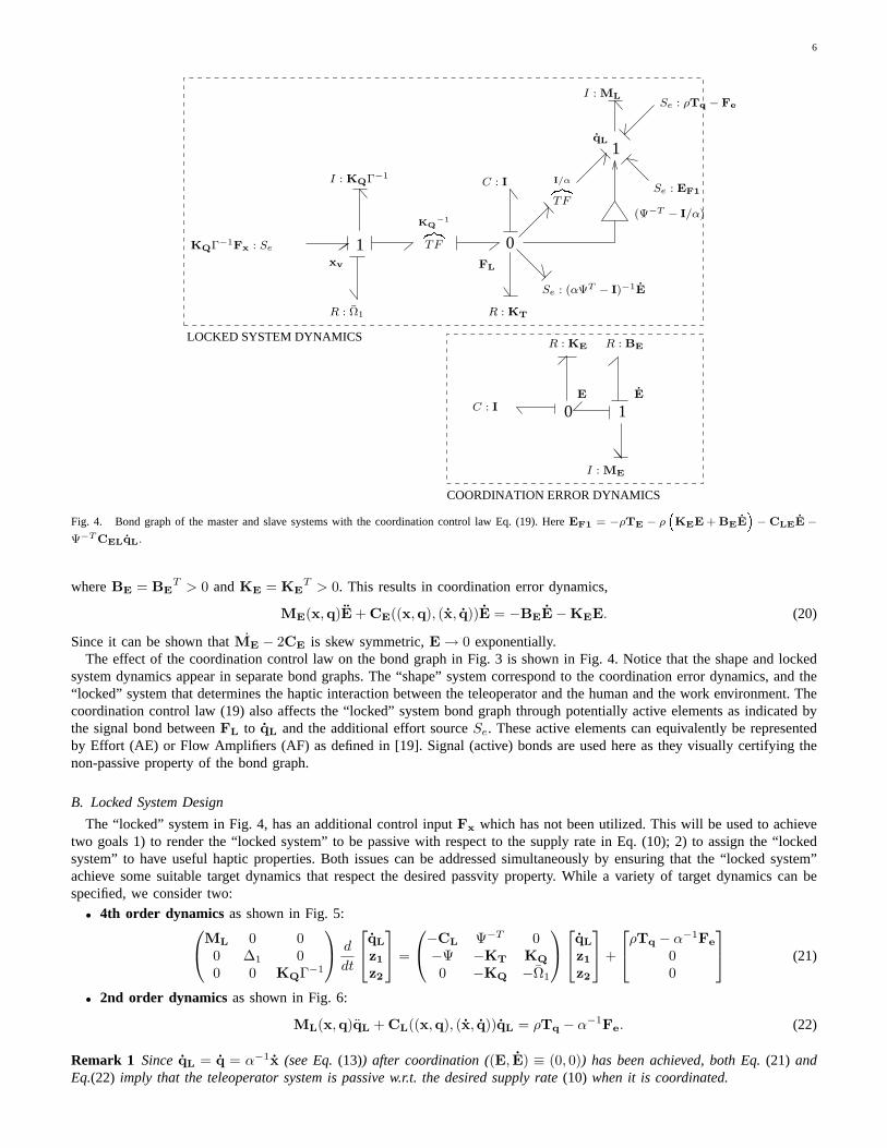
Fig. 4. Bond graph of the master and slave systems with the coordination control law Eq. (19). HereEF1 = −ρTE − ρKEE + BEE
− CLEE −
Ψ−T CELqL.
whereBE = BET > 0 andKE = KE
T > 0. This results in coordination error dynamics,
ME(x,q)E + CE((x,q), (x, q))E = −BEE − KEE. (20)
Since it can be shown thatME − 2CE is skew symmetric,E → 0 exponentially.The effect of the coordination control law on the bond graph in Fig. 3 is shown in Fig. 4. Notice that the shape and locked
system dynamics appear in separate bond graphs. The “shape”system correspond to the coordination error dynamics, and the“locked” system that determines the haptic interaction between the teleoperator and the human and the work environment. Thecoordination control law (19) also affects the “locked” system bond graph through potentially active elements as indicated bythe signal bond betweenFL to qL and the additional effort sourceSe. These active elements can equivalently be representedby Effort (AE) or Flow Amplifiers (AF) as defined in [19]. Signal (active) bonds are used here as they visually certifying thenon-passive property of the bond graph.
B. Locked System Design
The “locked” system in Fig. 4, has an additional control input Fx which has not been utilized. This will be used to achievetwo goals 1) to render the “locked system” to be passive with respect to the supply rate in Eq. (10); 2) to assign the “lockedsystem” to have useful haptic properties. Both issues can beaddressed simultaneously by ensuring that the “locked system”achieve some suitable target dynamics that respect the desired passvity property. While a variety of target dynamics canbespecified, we consider two:
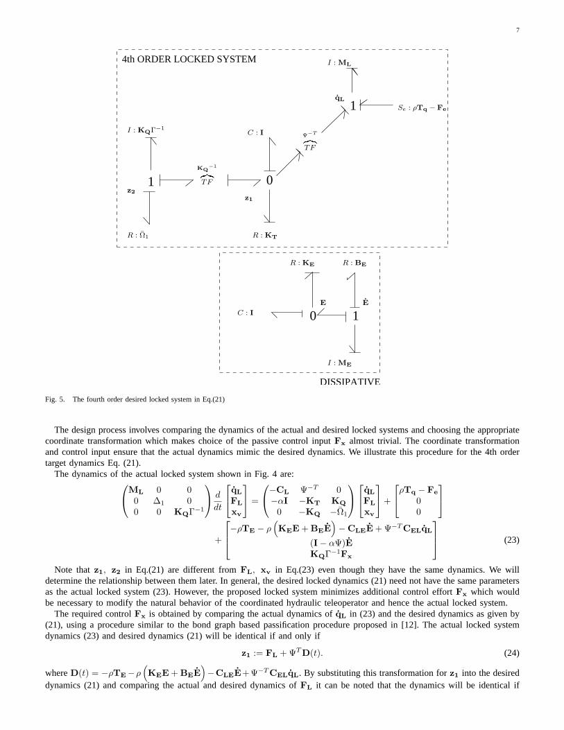
• 4th order dynamics as shown in Fig. 5:
ML 0 00 ∆1 00 0 KQΓ−1
d
dt
qL
z1
z2
=
−CL Ψ−T 0−Ψ −KT KQ
0 −KQ −Ω1
qL
z1
z2
+
ρTq − α−1Fe
00
(21)
• 2nd order dynamics as shown in Fig. 6:
ML(x,q)qL + CL((x,q), (x, q))qL = ρTq − α−1Fe. (22)
Remark 1 Since qL = q = α−1x (see Eq. (13)) after coordination ((E, E) ≡ (0, 0)) has been achieved, both Eq. (21) andEq.(22) imply that the teleoperator system is passive w.r.t. the desired supply rate (10) when it is coordinated.
7
1 0
1
DISSIPATIVE
4th ORDER LOCKED SYSTEM
0 1
I : KQΓ−1
KQ−1z|
TF
Ψ−Tz|TF
z1
R : KTR : Ω1
I : ML
z2
E
Se : ρTq − Fe
qL
I : ME
R : KE
E
R : BE
C : I
C : I
Fig. 5. The fourth order desired locked system in Eq.(21)
The design process involves comparing the dynamics of the actual and desired locked systems and choosing the appropriatecoordinate transformation which makes choice of the passive control inputFx almost trivial. The coordinate transformationand control input ensure that the actual dynamics mimic the desired dynamics. We illustrate this procedure for the 4th ordertarget dynamics Eq. (21).
The dynamics of the actual locked system shown in Fig. 4 are:
ML 0 00 ∆1 00 0 KQΓ−1
d
dt
qL
FL
xv
=
−CL Ψ−T 0−αI −KT KQ
0 −KQ −Ω1
qL
FL
xv
+
ρTq − Fe
00
+
−ρTE − ρ(
KEE + BEE)
− CLEE + Ψ−T CELqL
(I − αΨ)EKQΓ−1Fx
(23)
Note thatz1, z2 in Eq.(21) are different fromFL, xv in Eq.(23) even though they have the same dynamics. We willdetermine the relationship between them later. In general,the desired locked dynamics (21) need not have the same parametersas the actual locked system (23). However, the proposed locked system minimizes additional control effortFx which wouldbe necessary to modify the natural behavior of the coordinated hydraulic teleoperator and hence the actual locked system.
The required controlFx is obtained by comparing the actual dynamics ofqL in (23) and the desired dynamics as given by(21), using a procedure similar to the bond graph based passification procedure proposed in [12]. The actual locked systemdynamics (23) and desired dynamics (21) will be identical ifand only if
z1 := FL + ΨT D(t). (24)
whereD(t) = −ρTE−ρ(
KEE + BEE)
−CLEE+Ψ−T CELqL. By substituting this transformation forz1 into the desireddynamics (21) and comparing the actual and desired dynamicsof FL it can be noted that the dynamics will be identical if

8
and only if
z2 := KQ−1(ΨT − αI)qL + xv + KQ
−1
[
KTΨT D(t) +d
dt[∆1Ψ
T D(t)]
]
. (25)
Proceeding in this manner, the above analysis leads to the following coordinate transformation[qL FL xv]T 7→ [qL z1 z2]T :
qL
z1
z2
=
I 0 00 I 0
KQ−1(Ψ−1 − αI) 0 I
qL
FL
xv
+
0ΨT D(t)
KQ−1
(KTΨT D(t) + d
dt [∆1ΨT D(t)]
)
, (26)
whereD(t) = −ρTE − ρ(
KEE + BEE)
−CLEE + Ψ−T CELqL. Applying Eq. (26) to the actual locked system dynamics(23) results in the following transformed dynamics:
ML 0 00 ∆1 00 0 KQΓ−1
d
dt
qL
z1
z2
=
−CL Ψ−T 0−ΨT −KT KQ
0 −KQ −Ω1
qL
z1
z2
+
ρTq − Fe
0KQΓ−1Fx + D2(t)
, (27)
where
D2(t) = KQ[z1 FL] + KQΓ−1
(
Ω[z2 xv] +d
dt[z2 xv]
)
, (28)
z1 FL := ΨT D(t),
z2 xv := KQ−1(Ψ−1 − αI)qL + KQ
−1
(
KTΨT D(t) +d
dt[∆1Ψ
T D(t)]
)
.
Notice that the signalsz1 FL and z1 xv depend onD(t) and its successive derivatives which are functions of the externalvariablesTE, qL,FL,E and E. If the locked system controlFx in (27) is chosen as follows:
KQΓ−1Fx = −D2(t), (29)
then the target locked system dynamics Eq. (21) will be achieved.In summary,• the coordination control law given in Eq. (19) ensures that the teleoperator will be coordinated so thatE = αq− x → 0
exponentially (see (20))• the locked system control law given byFx in Eq. (29) and the preceding transformations ensure that the desired target
system dynamics (21) are achieved. SinceqL = q = α−1x and Eq. (21) is passive with respect to the supply rate,stele((Tq,−Fe), (qL, qL)) = qT
L(ρTq − Fe) which is equivalent to
stele((Tq,−Fe), (qL, qL)) = qTL(ρTq − Fe) = ρqTq − xFe
A similar locked system design procedure can be applied to achieve the 2nd order target dynamics Eq.(22). Compared to the4th order target dynamics, the high frequency content of human and environment forces are not filtered as much, resultingin amore transparent and responsive haptic feel. Since the original dynamics (23) is 4th order, the locked system control involveslowering the relative degree through feedforward actions.Due to space limitations, the algorithm is not presented here. Readersare referred to [13] for details.
For both the 4th and 2nd order target dynamics cases, the valve and the joystick control forcesFx andFq assume accurateknowledge ofΨ, TE which depend on the backhoe / joystick inertia and external forces respectively. In reality, it may notbe possible to know these parameters exactly. It is however possible to modify the control algorithms (such as some form ofdiscontinuous control) so as to ensure the coordination andpassivity properties [13].
IV. EXPERIMENTAL RESULTS
In the experimental setup in Fig. 1, the joystick is powered by a set of DC motors and instrumented with angular positionencoders, and a JR3 force sensor for measuring the operator input force. The hydraulic system consists of a pressure compensated19 LPM (5 GPM) flow pump operating at 6.9 MPa (1000 PSI); a set ofVickers KBFDG4V-5 series proportional valves that havebeen actively passified [7] and have bandwidths of about 50 Hz; single rod hydraulic actuators instrumented with displacementsensors and chamber pressures sensors. A PC running MATLAB (MA) xPC Target provides real time control at a sample rateof 1 KHz.
The conducted experiments are typical of a digging task. Thebackhoe is teleoperated to dig into a sand box. A woodenbox is buried in the sandbox to mimic an underground obstacle. A kinematic scaling ofα = 5in./rad and a power scalingρ = 12 are used. Both the 4th and 2nd order locked system teleoperation algorithm are tested. For comparison, the algorithmin [11] that assumes a kinematic model of the hydraulic backhoe and neglects the compressibility and inertial dynamics wasimplemented as well.

9
2nd ORDER LOCKED SYSTEM
0 1
1 0
1DISSIPATIVE
DISSIPATIVE
I : KQΓ−1
KQ−1z|
TF
Se : Ψ−T z1
z1
R : KTR : Ω1
I : ML
z3
E
Se : ρTq − Fe
qL
I : ME
R : KE
E
R : BE
C : I
C : I
Fig. 6. Second order desired locked system
A. Previous algorithm [11]
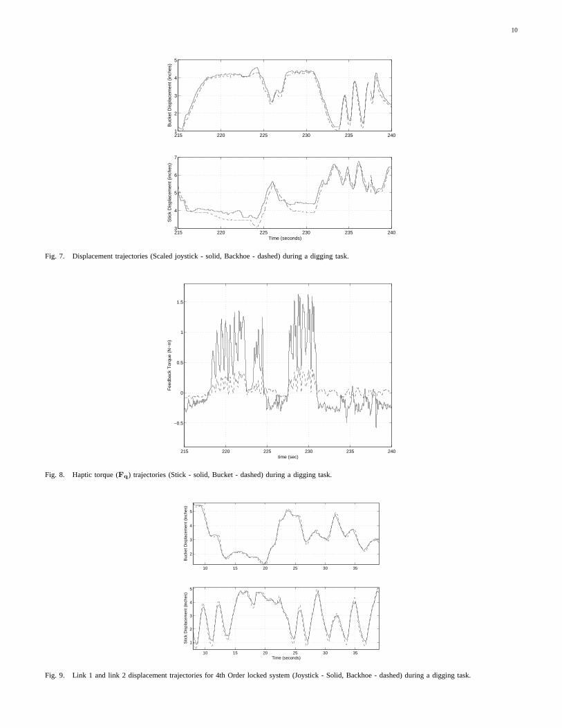
The teleoperated trajectories of the bucket and the stick (and their corresponding joystick links) are shown in Fig. 7. Thecorresponding haptic force (Fq) experienced by the operator is shown in Fig. 8.
The maximum observed coordination error as shown in Fig. 7 iswithin 0.5in. When the backhoe hits the wooden box(t = 218 and t = 228), severe oscillations in the haptic force is experienced bythe operator as shown in Fig. 8. This is aresult of neglecting compressibility and inertia dynamics.
B. 4th order locked system
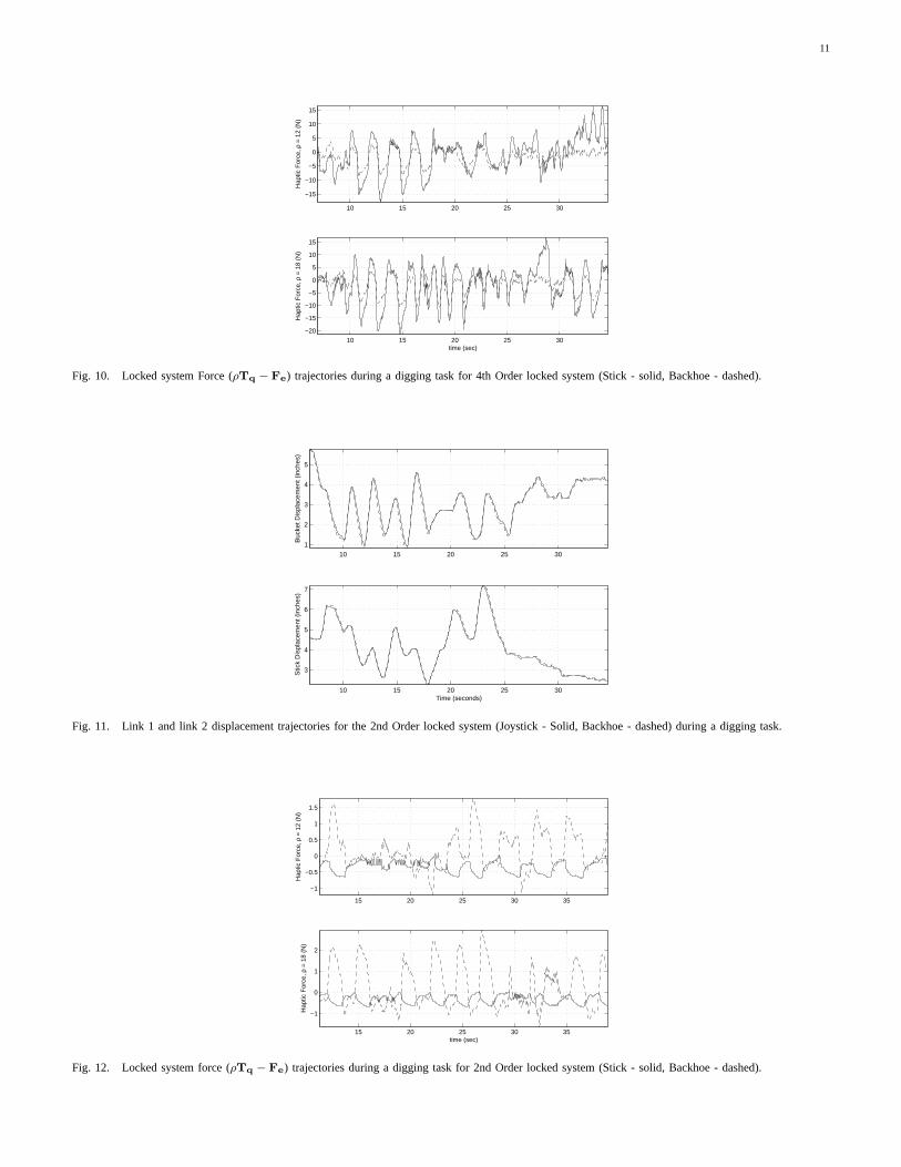
The results for the control law that mimics the 4th order target locked system (21) are shown in Fig. 9-Fig. 10. The maximumobserved coordination error in Fig. 9 is within0.1in which is significantly better than that in Fig. 7 for the previous controller.Also, as the backhoe hits the underground wooden box (aboutt = 18s), there are no oscillations (Fig. 10). Notice that theoperator force is balanced by the work environment force when the interacting with the wooden box as indicated by the netforce being nearly zero (Fig. 10).
C. 2th order locked system
The results for the control law that mimics the 2th order target locked system (22) are shown in Fig. 11-Fig. 12. Themaximum observed coordination error in Fig. 11 is within0.01in which is even better than that in Fig. 9 for the 4th orderlocked system controller. There are again no oscillations when the backhoe hits the underground wooden box (aboutt = 16and t = 19s) (Fig. 10).
It is interesting to note that for similar operating speeds,the force range for the 2nd order locked system (Fig. 12) is only20 % of that for the 4th order locked system (Fig. 10). This is an indication that the 2nd order locked system is easier (interms of necessary power) to teleoperate than the 4th order locked system. The operator also reported that the teleoperator ismore responsive is more able to feel the environment force using the 2nd order target system controller than the 4th ordertarget system controller.
10
215 220 225 230 235 2401
2
3
4
5
Buc
ket D
ispl
acem
ent (
inch
es)
215 220 225 230 235 2403
4
5
6
7
Time (seconds)
Stic
k D
ispl
acem
ent (
inch
es)
Fig. 7. Displacement trajectories (Scaled joystick - solid,Backhoe - dashed) during a digging task.
215 220 225 230 235 240
−0.5
0
0.5
1
1.5
time (sec)
Fee
dbac
k T
orqu
e (N
−m
)
Fig. 8. Haptic torque (Fq) trajectories (Stick - solid, Bucket - dashed) during a digging task.
10 15 20 25 30 35
2
3
4
5
Buc
ket D
ispl
acem
ent (
inch
es)
10 15 20 25 30 35
1
2
3
4
5
Time (seconds)
Stic
k D
ispl
acem
ent (
inch
es)
Fig. 9. Link 1 and link 2 displacement trajectories for 4th Order locked system (Joystick - Solid, Backhoe - dashed) duringa digging task.
11
10 15 20 25 30
−15
−10
−5
0
5
10
15
Hap
tic F
orce
, ρ =
12
(N)
10 15 20 25 30−20
−15
−10
−5
0
5
10
15
time (sec)
Hap
tic F
orce
, ρ =
18
(N)
Fig. 10. Locked system Force (ρTq − Fe) trajectories during a digging task for 4th Order locked system (Stick - solid, Backhoe - dashed).
10 15 20 25 30
1
2
3
4
5
Buc
ket D
ispl
acem
ent (
inch
es)
10 15 20 25 30
3
4
5
6
7
Time (seconds)
Stic
k D
ispl
acem
ent (
inch
es)
Fig. 11. Link 1 and link 2 displacement trajectories for the 2nd Order locked system (Joystick - Solid, Backhoe - dashed) during a digging task.
15 20 25 30 35
−1
−0.5
0
0.5
1
1.5
Hap
tic F
orce
, ρ =
12
(N)
15 20 25 30 35
−1
0
1
2
time (sec)
Hap
tic F
orce
, ρ =
18
(N)
Fig. 12. Locked system force (ρTq − Fe) trajectories during a digging task for 2nd Order locked system (Stick - solid, Backhoe - dashed).

12
V. CONCLUSIONS
A passive teleoperation control algorithm for backhoe operation is proposed. The passivity property of the teleoperationscheme ensures stability of interaction of the teleoperated backhoe and a wide range of human / work environment. Usinga bond graph based design procedure, neglected compressibility and inertial dynamics can be accounted for, thus rectifyinga previously developed algorithm which assumed a kinematicmodeled backhoe. This results in significant improvement incoordination performance that has been verifies in experiments. Moreover, the present approach allows the user to specify adesired target locked system dynamics which directly affect transparency and haptic sensation of the system. In particular, the2nd order target system is more responsive and more transparent than the 4th order target system.
Although the control design ensures that the closed loop system becomes passive after coordination has been achieved,the control law is not an Intrinsically Passive Controller (IPC), unlike the algorithm in [8]. An IPC has the advantage ofguaranteeing passivity of the teleoperated backhoe even under significant system variation and uncertainties. Development ofsuch a controller will greatly enhance the robustness properties of the teleoperated backhoe.
REFERENCES
[1] Vidyasagar, M., 1993. “Nonlinear systems analysis”.Prentice Hall [].[2] Li, P. Y., and Horowitz, R., 1997. “Control of smart machines, part 1: problem formulation and non-adaptive control”. IEEE/ASME Transactions on
Mechatronics,2 (4) [December], pp. 237–247.[3] Lee, D., and Li, P., 2005. “Passive coordination controlof nonlinear mechanical teleoperator”. IEEE Transactions on Robotics,21 (5) [October],
pp. xxx–xxx. In press.[4] Lee, D., and Li, P., 2003. “Passive bilateral feedforward control of linear dynamically similar teleoperated manipulators”. IEEE Transactions on Robotics
and Automation,19 (3) [June], pp. 443–456.[5] Colgate, J. E., Wannasuphoprasit, W., and Peshkin, M. A., 1996. “Cobots: Robots for collaboration with human operators”. Proceedings of the ASME
Dynamic Systems and Control Division, 58 [], pp. 433–439.[6] Gomes, M. W., and Book, W., 1997. “Control approaches for adissipative passive trajectory enhancing robot”.IEEE/ASME Conference on Advanced
Intelligent Mechatronics [].[7] Li, P. Y., 2000. “Towards safe and human friendly hydraulics: The passive valve”. ASME Journal of Dynamic Systems, Measurement and Control,122
(3) [Sep.], pp. 402–409.[8] Li, P. Y., and Krishnaswamy, K., 2004. “Passive bilateralteleoperation of a hydraulic actuator using an electrohydraulic passive valve”.International
Journal of Fluid Power [August], pp. 43–56.[9] Krishnaswamy, K., and Li, P. Y., 2002. “Passification of a two-stage pressure control servo-valve”.Proceedings of the American Control Conference,
Anchorage, AK, 6 [May], pp. 4831–4836.[10] Krishnaswamy, K., and Li, P. Y., 2002. “Single degree of freedom passive bilateral teleoperation of an electrohydraulic actuator using a passive multi-stage
valve”. Proceedings of the IFAC Mechatronics Conference, Berkeley, CA [Dec].[11] Krishnaswamy, K., and Li, P. Y., 2003. “Passive teleoperation of a multiple degree of freedom hydraulic backhoe usinga dynamic passive valve”.
Proceedings of the ASME-IMECE [].[12] Li, P. Y., and Ngwompo, R. F., 2005. “Power scaling bondgraph approach to the passification of mechatronic systems - withapplication to electrohydraulic
valves”. ASME Journal of Dynamic Systems, Measurement and Control, 127 (4) [Dec.], pp. xxx–xxx. In press. Also appeared in Proceedings of 15thIFAC World Congress, 2002.
[13] Krishnaswamy, K., 2004.Passive Teleoperation of Hydraulic Systems. PhD thesis, Department of Mechanical Engineering, University of Minnesota,May. PhD Thesis. Available athttp://www.me.umn.edu/˜ kk/thesis .
[14] Lee, D. J., 2004.Passive Decomposition and Control of Interactive Mechanical Systems under Motion Coordination Requirements. PhD thesis, Departmentof Mechanical Engineering, University of Minnesota, May.
[15] Merritt, H. E., 1967.Hydraulic Control Systems. John Wiley & Sons.[16] Li, P. Y., 1998. “Passive control of bilateral teleoperated manipulators”.Proceedings of the 1998 American Control Conference [], pp. 3838–3842.[17] Gawthrop, P. J., 1995. “Bicausal bond graphs”.Proceedings of the International Conference on Bond Graph Modeling and simulation (ICBGM) [],
pp. 83–88.[18] Ngwompo, R. F., Scavarda, S., and Thomasset, D., 2001. “Physical model-based inversion in control systems design usingbond graph representation
part 1: theory”.Proceedings of the Institute of Mechanical Engineers, 215 [], pp. 95–103.[19] Ngwompo, R. F., and Gawthrop, P. J., 1999. “Bond graph based simulation of nonlinear inverse systems using physical performance specifications”.
Journal of the Franklin Institute, 336 [], pp. 1225–1247.