1. bridge dynamics - sginstitute.in · bridge dynamics suhasini madhekar ... irc 18 design criteria...
TRANSCRIPT

Bridge DynamicsBridge Dynamics
Suhasini Madhekar Suhasini Madhekar
College of Engineering PuneCollege of Engineering Pune
Faculty Development Program onFaculty Development Program on
Fundamentals of Structural Dynamics and Application to Fundamentals of Structural Dynamics and Application to
Earthquake EngineeringEarthquake Engineering
1212thth December 2015December 2015
Sanjay Sanjay GhodawatGhodawat Group of InstitutionsGroup of Institutions
AtigreAtigre, Kolhapur, Kolhapur 11

Presentation OutlinePresentation Outline
BridgesBridges aroundaround thethe worldworld
BehaviourBehaviour ofof bridgesbridges duringduring pastpast earthquakesearthquakes
MajorMajor componentscomponents ofof BridgeBridgeMajorMajor componentscomponents ofof BridgeBridge
BridgeBridge DynamicsDynamics andand BridgeBridge modelingmodeling
SeismicSeismic considerationsconsiderations forfor BridgesBridges
ConclusionsConclusions
22

Dynamic forces acting on BridgesDynamic forces acting on Bridges
WindWind
EarthquakeEarthquake
BlastBlast
Barge Impact / vehicle impactBarge Impact / vehicle impact
Flood : Buoyancy : Submersible bridges Flood : Buoyancy : Submersible bridges
33

Difference Difference Between WindBetween Wind--Resistant DesignResistant Design
and Earthquakeand Earthquake--Resistant DesignResistant Design
For Wind:For Wind:
Excitation is an applied Excitation is an applied pressure or force on the facade.pressure or force on the facade.
Loading is dynamic but response is nearly static for most Loading is dynamic but response is nearly static for most
structures.structures.structures.structures.
Structure deforms due to applied force.Structure deforms due to applied force.
Deformations are monotonic (unidirectional).Deformations are monotonic (unidirectional).
Structure is designed to respond elastically under factored loads.Structure is designed to respond elastically under factored loads.
The controlling life safety limit state is strength.The controlling life safety limit state is strength.
Enough strength is provided to resist forces elastically.Enough strength is provided to resist forces elastically. 44
Difference Between WindDifference Between Wind--Resistant DesignResistant Design
and Earthquakeand Earthquake--Resistant DesignResistant Design
For Earthquake:For Earthquake:
Excitation is an applied displacement at the base.Excitation is an applied displacement at the base.
Loading and response are truly dynamic.Loading and response are truly dynamic.
Structural system deforms as a result of inertial forces.Structural system deforms as a result of inertial forces.Structural system deforms as a result of inertial forces.Structural system deforms as a result of inertial forces.
Deformations are fully reversed.Deformations are fully reversed.
Structure is designed Structure is designed to respond to respond inelasticallyinelastically under factored under factored
loadsloads. Enough . Enough strength is provided to ensure that strength is provided to ensure that the the
structure withstands inelastic deformationsstructure withstands inelastic deformations
Demands Demands do not exceed deformation capacitydo not exceed deformation capacity
..
55

Bridge failures in Past Earthquakes Bridge failures in Past Earthquakes Bridge failures in Past Earthquakes Bridge failures in Past Earthquakes
66

Collapse of Collapse of NakazunoNakazuno Bridge : 1948 Fukui Earthquake, Japan Bridge : 1948 Fukui Earthquake, Japan 77

Failure of foundations due to soil liquefaction resulted Failure of foundations due to soil liquefaction resulted
in collapse of the bridge : in collapse of the bridge : NigataNigata Earthquake JapanEarthquake Japan88

Damage to SuperstructureDamage to Superstructure
Steel Steel superstructure failure and superstructure failure and collapse of Eastern collapse of Eastern
portion of portion of the San Franciscothe San Francisco––Oakland Bay Bridge Oakland Bay Bridge
(1989 (1989 Loma Loma PrietaPrieta earthquake) earthquake) 99
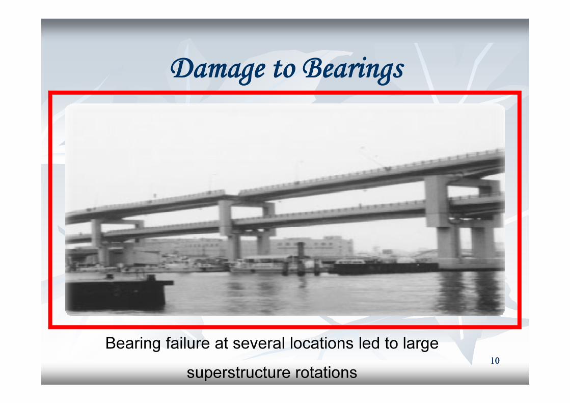
Damage to BearingsDamage to Bearings
Bearing failure at several locations led to large
superstructure rotations 1010

1991 Costa Rica earthquake (1991)
Abutment rotated due to liquefaction and lateral spreading
(lateral sliding of gently sloping ground due to soil
liquefaction at relatively shallow depth ) 1111
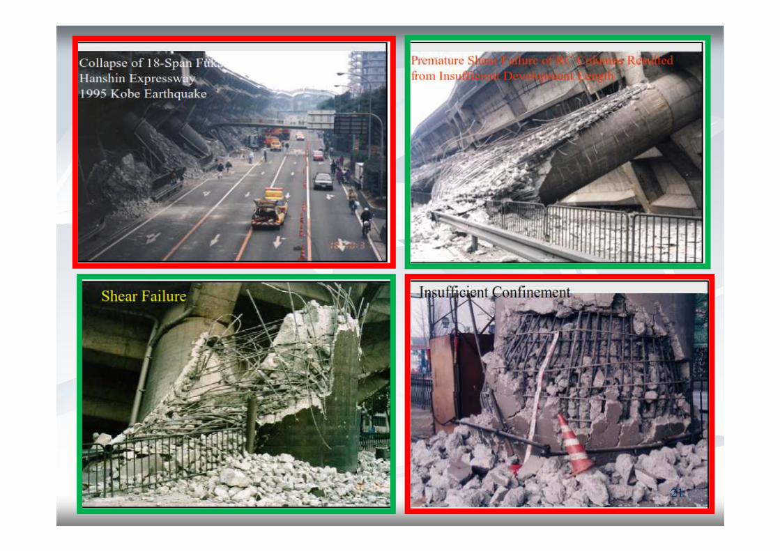
Failure of 18 Span Viaduct in Kobe Earthquake Failure of 18 Span Viaduct in Kobe Earthquake
Damage resulted from insufficient consideration on ductility of Damage resulted from insufficient consideration on ductility of
columns and insufficient strength of bearings.columns and insufficient strength of bearings.
The most extensive damage occurred at a 18 The most extensive damage occurred at a 18 -- span viaduct. It span viaduct. It
collapsed due to failure of RC columns which resulted from the collapsed due to failure of RC columns which resulted from the
premature shear failure.premature shear failure.premature shear failure.premature shear failure.
Northridge earthquake: Costliest natural disaster in the history of Northridge earthquake: Costliest natural disaster in the history of
USA. Six bridges collapsed on the major freeways. USA. Six bridges collapsed on the major freeways.
The main failure types of bridges are classified in two groupsThe main failure types of bridges are classified in two groups
Failure of abutments and piersFailure of abutments and piers
Failure of superstructuresFailure of superstructures1212

First Tacoma Narrows Bridge, First Tacoma Narrows Bridge, USAUSA
CollapseCollapse ofof suspensionsuspension bridgesbridges duedue toto windwind :: TacomaTacoma
NarrowsNarrows BridgeBridge DisasterDisaster
BridgeBridge provedproved toto bebe veryvery sensiblesensible toto windwind forcesforces andand waswas
excitedexcited toto laterallateral asas wellwell asas verticalvertical vibrationsvibrations..excitedexcited toto laterallateral asas wellwell asas verticalvertical vibrationsvibrations..
OnOn NovemberNovember 77,, 19401940,, exposedexposed toto aa modestmodest laterallateral windwind ofof
1919 m/m/ ss thethe suspensionsuspension bridgebridge movedmoved inin longitudinallongitudinal waveswaves
upup andand downdown withwith aa twistingtwisting deckdeck andand eventuallyeventually thethe hangershangers
rupturedruptured.. TheThe centralcentral spanspan ofof 853853 mm fellfell downdown andand sunksunk intointo
thethe riverriver..1313

TheThe firstfirst TacomaTacoma NarrowsNarrows suspensionsuspension bridgebridge collapsedcollapsed duedue toto windwind--inducedinduced
vibrationsvibrations onon NovNov.. 77,, 19401940.. TheThe bridgebridge waswas engineeredengineered itit toto withstandwithstand hurricanehurricane
winds,winds, butbut thethe windwind thatthat dayday waswas onlyonly 4040 mphmph…… whatwhat happened!?happened!? 1414

Accidental Accidental overload and overload and impact of vehicles with main impact of vehicles with main
structural elements of bridge : structural elements of bridge : ship collisions with bridge ship collisions with bridge
piers.piers.
Causes of Bridge Causes of Bridge FailuresFailures
Structural Structural and design and design deficiencies deficiencies
Scour of foundations in river bedScour of foundations in river bed
Construction Construction and supervision and supervision mistakesmistakes
Lack Lack of maintenance and inspection.of maintenance and inspection.
1515
Causes of Bridge Causes of Bridge FailuresFailures
Under strong ground excitations, highway bridge structures
experience severe nonlinear behaviors : Yielding and plastic
deformation of pier members
The pounding between adjacent decks induced by the local
failure of hinge bearings
Bridges of the BMHWB kind are quite common on highway
river-crossings all over the world.
1616

Distribution of Bridges Collapse causesDistribution of Bridges Collapse causesEarthquakesEarthquakes
1717
Structural and Design DeficienciesStructural and Design Deficiencies
Incorrect assumption of loadsIncorrect assumption of loads. .
Many bridges Many bridges collapsed due to static and / or dynamic wind collapsed due to static and / or dynamic wind
forces : Tacoma Narrows (1940). forces : Tacoma Narrows (1940). forces : Tacoma Narrows (1940). forces : Tacoma Narrows (1940).
Besides Besides using long using long term statistics term statistics to reliably estimate the to reliably estimate the
wind force, nowadays wind wind force, nowadays wind tunnel tests tunnel tests are performed to are performed to
verify structures that are verify structures that are especially sensitive especially sensitive to wind forcesto wind forces..
1818

Superstructure FailuresSuperstructure Failures
1919

2020
2121

Buckling of bridge pier in HanshinBuckling of bridge pier in Hanshin--Awaji Awaji
earthquake : 17earthquake : 17thth January 1995January 1995
2222

Failure of Steel PiersFailure of Steel Piers
2323

Shear failure of RC columnsShear failure of RC columns
2424
Development of ClausesDevelopment of Clauses
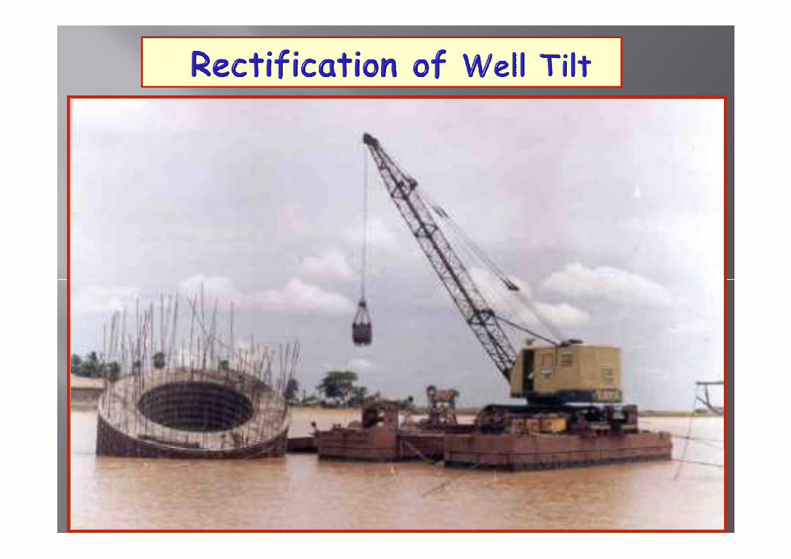
Till 1948, seismic effects were not considered / poorly Till 1948, seismic effects were not considered / poorly
considered in design : Tilting, Overturning and settlement of considered in design : Tilting, Overturning and settlement of
foundations occurred.. Leading to extensive damages and foundations occurred.. Leading to extensive damages and
collapse..collapse..collapse..collapse..
Construction of massive & rigid piers with large sections Construction of massive & rigid piers with large sections
started. started.
In 1960In 1960--1970s : Importance of considering soil liquefaction 1970s : Importance of considering soil liquefaction
and unseating prevention devices was first recognised. and unseating prevention devices was first recognised.
2525

Development of Development of
Unseating prevention devicesUnseating prevention devices
2626
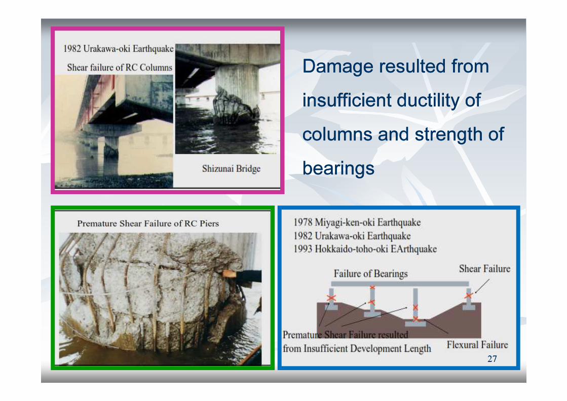
Damage resulted from Damage resulted from
insufficient ductility of insufficient ductility of
columns and strength of columns and strength of
bearingsbearings
2727

Ductile DetailingDuctile Detailing
2828

Seismic Design Practice in JapanSeismic Design Practice in Japan
2929

Extensive Damage of BearingsExtensive Damage of Bearings
3030

Performance of BearingsPerformance of Bearings
ChiChi––Chi Chi earthquake earthquake (1999, M7.3), Taiwan (1999, M7.3), Taiwan : Improper : Improper
functioning of bearings can lead to deckfunctioning of bearings can lead to deck--falling failure falling failure
The The gap of joints between decks can have a significant effect gap of joints between decks can have a significant effect
on the response of a bridgeon the response of a bridge
When When sliding and pounding occurs, accelerations of bridge sliding and pounding occurs, accelerations of bridge
decks may increase by a factor of decks may increase by a factor of 10, 10, as compared to that as compared to that
without pounding.without pounding.
The abrupt increase of accelerations can result in severe The abrupt increase of accelerations can result in severe
impact forces that damage structural members like the deck impact forces that damage structural members like the deck
or pier.or pier.3131

Design of BearingsDesign of Bearings
3232

Damage of Unseating Prevention Damage of Unseating Prevention
DevicesDevices
3333

Experience of 1995 Kobe EarthquakeExperience of 1995 Kobe Earthquake
3434
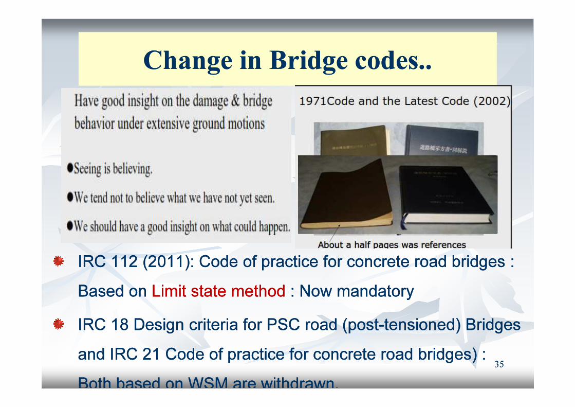
Change in Bridge codes..Change in Bridge codes..
IRC 112 (2011): Code of practice for concrete road bridges : IRC 112 (2011): Code of practice for concrete road bridges :
Based on Based on Limit state method Limit state method : Now mandatory: Now mandatory
IRC 18 Design criteria for PSC road (postIRC 18 Design criteria for PSC road (post--tensioned) Bridges tensioned) Bridges
and IRC 21 Code of practice for concrete road bridges) : and IRC 21 Code of practice for concrete road bridges) :
Both based on WSM are withdrawn. Both based on WSM are withdrawn.
3535

Optimal performance achieved Optimal performance achieved by by
�� Providing Providing competent load pathcompetent load path
�� Providing Providing redundancy redundancy
�� Avoiding Avoiding configuration irregularitiesconfiguration irregularities
�� Proper Proper consideration of “consideration of “non non -- structural” elements structural” elements and and �� Proper Proper consideration of “consideration of “non non -- structural” elements structural” elements and and
componentscomponents
�� Avoiding Avoiding excessive massexcessive mass
�� Detailing Detailing for controlled energy dissipationfor controlled energy dissipation
�� Limiting Limiting deformation demandsdeformation demands
3636

Natural Natural and Added Dampingand Added Damping
3737
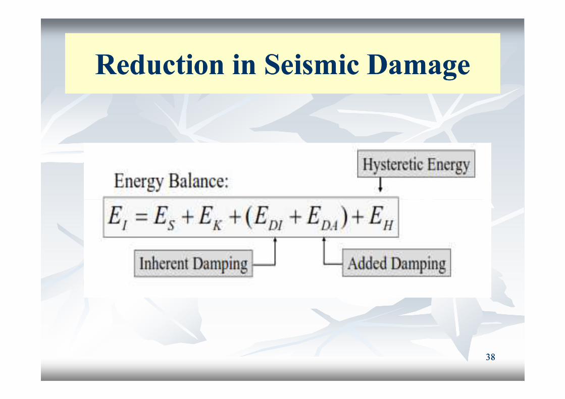
Reduction in Seismic DamageReduction in Seismic Damage
3838

Seismic Analysis of Structures with Passive EnergySeismic Analysis of Structures with Passive Energy
Dissipation SystemsDissipation Systems
3939
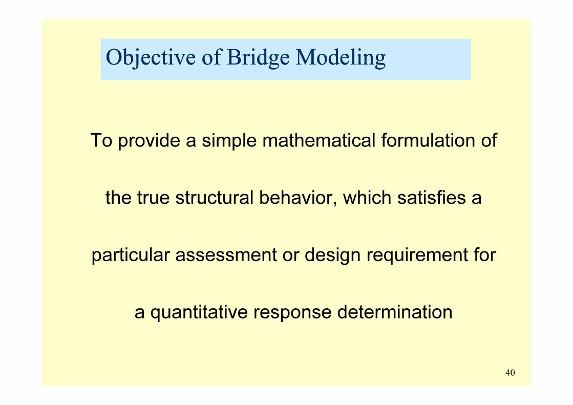
Objective of Bridge ModelingObjective of Bridge Modeling
To provide a simple mathematical formulation of
the true structural behavior, which satisfies a the true structural behavior, which satisfies a
particular assessment or design requirement for
a quantitative response determination
40

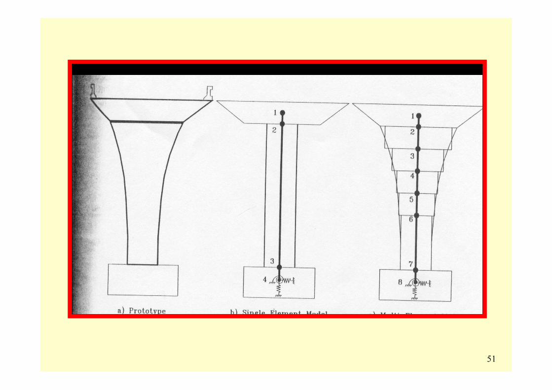
Types of modelsTypes of models
� Lumped parameter model:
Very simple ; but requires significant knowledge and
experience – Deformation relationship of few idealized
elements to represent the prototype bridge
� Structural component model:
Based on idealized Structural subsystems that are connected
to resemble the prototype
� Detailed FE Model: Huge computational effort required –
nonlinear analysis – cyclic response
41

42

43
44
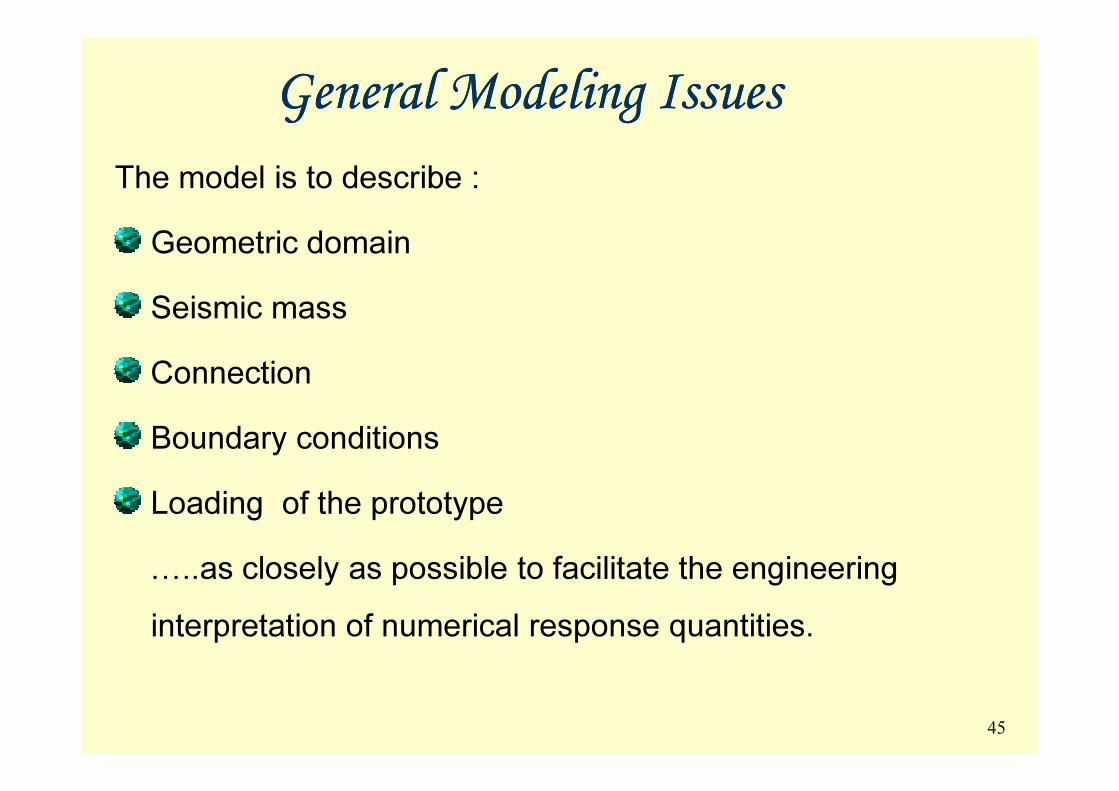
General Modeling IssuesGeneral Modeling Issues
The model is to describe :
Geometric domain
Seismic mass
Connection
Boundary conditions
Loading of the prototype
…..as closely as possible to facilitate the engineering
interpretation of numerical response quantities.
45
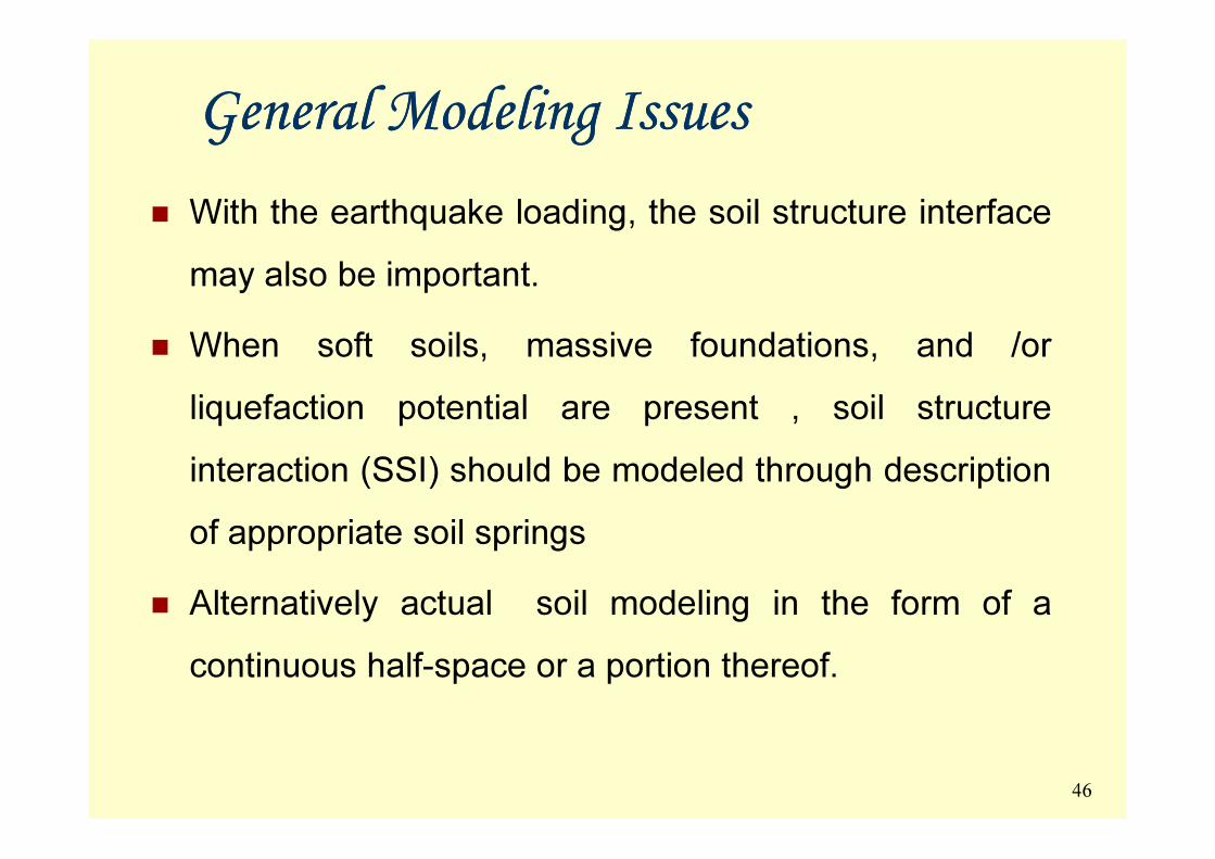
General Modeling IssuesGeneral Modeling Issues
� With the earthquake loading, the soil structure interface
may also be important.
� When soft soils, massive foundations, and /or
liquefaction potential are present , soil structure
interaction (SSI) should be modeled through description
of appropriate soil springs
� Alternatively actual soil modeling in the form of a
continuous half-space or a portion thereof.
46

Bridge Structural SystemBridge Structural System
� The total structural bridge system consists of the
superstructure and the substructures
� To reflect the importance and differences of different
individual subsystems in terms of the analytical modeling for
seismic bridge response quantification
(1) global models, (2) frame models, and (3 ) bent models.
47
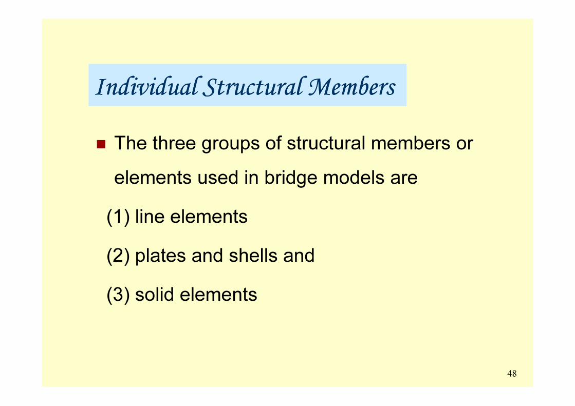
Individual Structural MembersIndividual Structural Members
� The three groups of structural members or
elements used in bridge models are
(1) line elements
(2) plates and shells and
(3) solid elements
48

49
50
51
Bridge FoundationsBridge Foundations
Most common footing types for bridge piers and
abutments :
(1) spread footings for stiff soil sites
(2) pile-supported cap footings for soft soil sites or
soil layers with liquefaction potential
(3) well foundations
52

Damage to FoundationsDamage to Foundations
5353

Pile Damage Pile Damage by by Lateral Spread Lateral Spread
1964, Niigata, Japan1964, Niigata, Japan
5454
Spread and Pile FootingsSpread and Pile Footings
Spread or pile footings are typically considered to be rigid
bodies that allow support conditions to be modeled at a
single point with boundary springs at the bottom of the
column or pier model at the end of the effective length
extension link into the footing.extension link into the footing.
For pile footings rotational stiffness is of greater significance
than lateral stiffness on overall bridge response.
The rotational stiffness and capacity of pile footings are
largely related to pile axial stiffness and the pile axial
capacities in compression and uplift.55

56
Shock Transmitting DevicesShock Transmitting Devices
� STU : Also known as ‘Lock Up’ Device (LUD)
� First use of STU : By Steinman, the designer of the
Carquinez Bridge in California, US (1927)
� STU : Forms a rigid link under rapidly applied loads � STU : Forms a rigid link under rapidly applied loads
- Braking and seismic forces
� Moves freely under slowly applied loads
- Temperature, creep and shrinkage
� The unit is connected between elements of bridge structures
- At expansion joints or near the bearings57

Shock Shock Transmitting DevicesTransmitting Devices
� Rapid passage of viscous fluid through the narrow gap, orifice
or part generates high resistance
� Simple dimensions and simple installation, no leakage
� Installation soon after the structure is completed
� STU’s connect superstructure to substructure elements :
according to space available between the soffit of deck and
the top of pier
� STU is connected by brackets and pins
� STUs: can reduce the seismic response of any part of the
structure 58

STU : AdvantagesSTU : Advantages
� Load sharing by means of an STU in new multi-span bridges
results in smaller design section for the substructure elements
� STUs can be made to strengthen supporting piers which have
been found inadequate due to increase in traction and been found inadequate due to increase in traction and
braking forces / seismic considerations
� Installation of STUs can be carried out without closing the
bridge traffic
� STU are maintenance free. Periodic visual inspection
necessary in order to check the corrosion protection system
59

Case Study of Jaitapur BridgeCase Study of Jaitapur Bridge
60

� Near Jaitapur
� Prestressed concrete box girder 2 span continuous unit
� span = 65m Thus unit is of 65 + 65
� Bridge length more than 500 m
� Concrete, steel
� Cast steel rocker - roller bearings
� Pier height : 6-8m, pier cap 7.0m x 3.0m x 3.0m depth
� Wells are all of different size ranging from 10m to 11.5 m dia 61
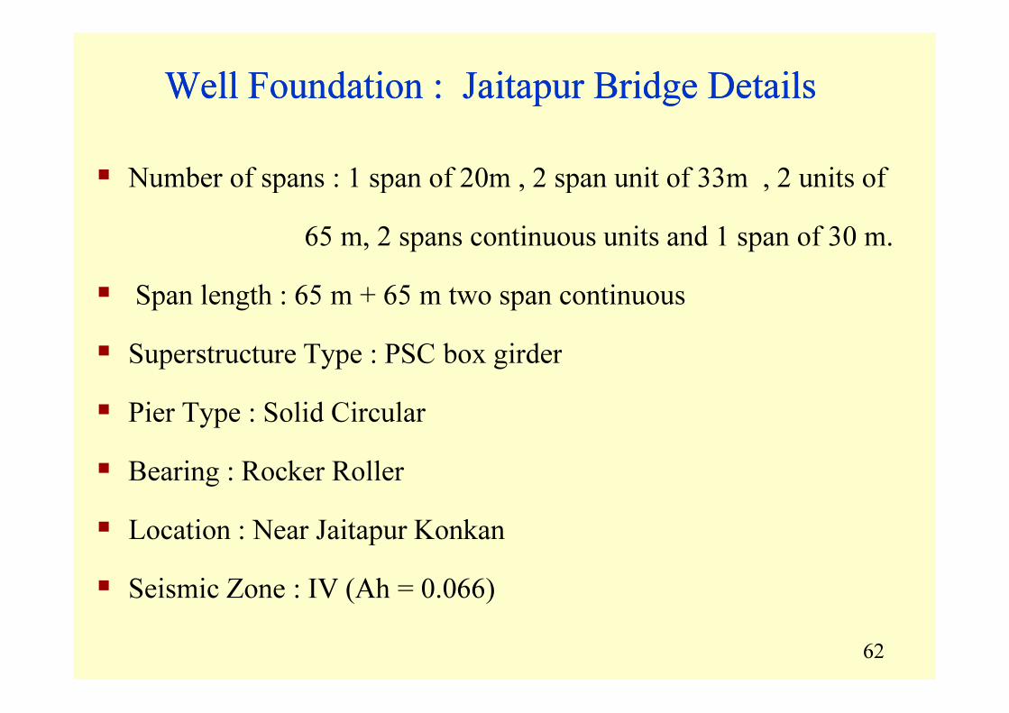
� Number of spans : 1 span of 20m , 2 span unit of 33m , 2 units of
65 m, 2 spans continuous units and 1 span of 30 m.
� Span length : 65 m + 65 m two span continuous
� Superstructure Type : PSC box girder
Well Foundation : Jaitapur Bridge Details Well Foundation : Jaitapur Bridge Details
62
� Superstructure Type : PSC box girder
� Pier Type : Solid Circular
� Bearing : Rocker Roller
� Location : Near Jaitapur Konkan
� Seismic Zone : IV (Ah = 0.066)

Components of well FoundationComponents of well Foundation
AccordingAccording toto thethe constructionconstruction sequencesequence ::
1) Cutting edge
2) Well Curb
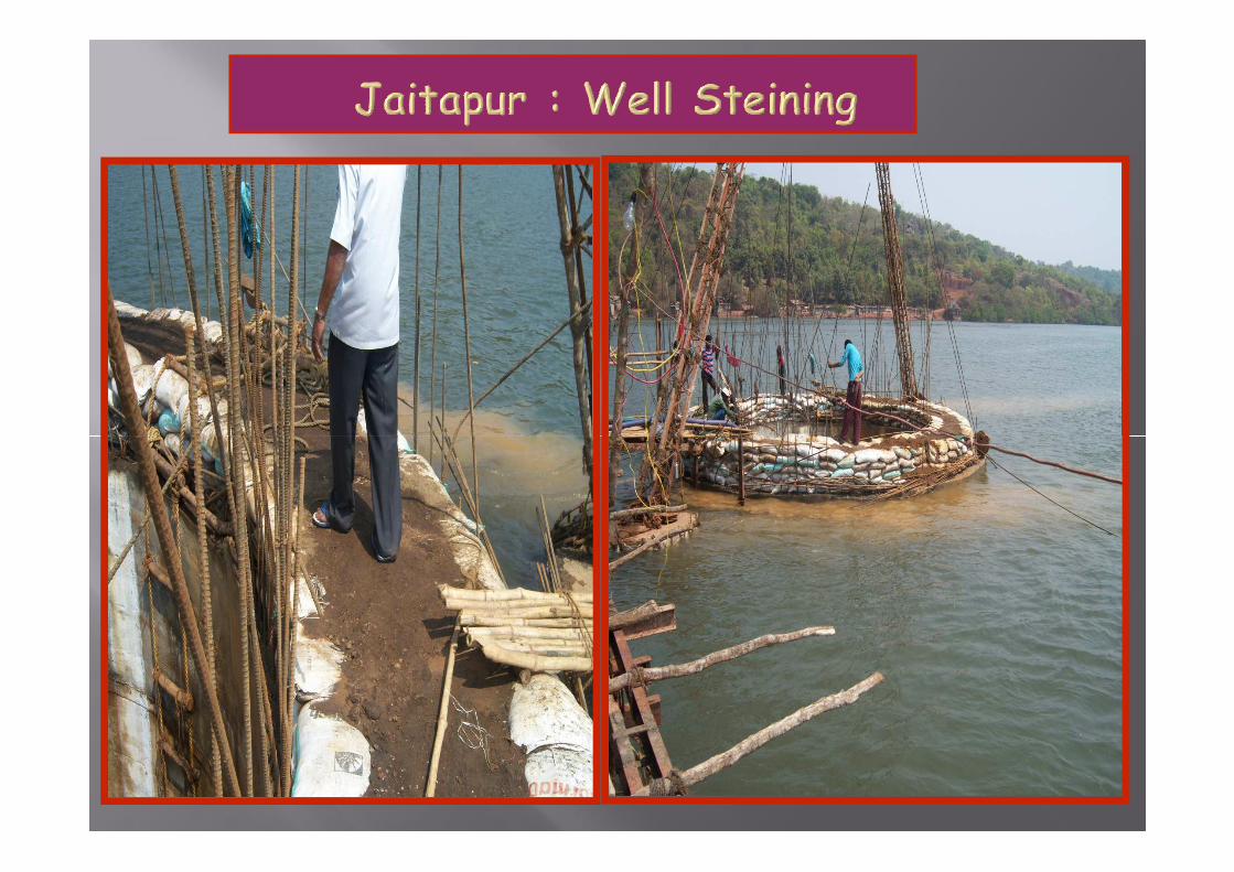
3) Well Steining
4) Bottom plug4) Bottom plug
5) Sand filling
6) Top Plug
7) Well cap

Island for grounding cutting edgeIsland for grounding cutting edge


Without STU With one STUWithout STU With one STU
Forces on Single Well Forces on Single Well Foundation Foundation
Dead load = 6820.00 kN
Bearing = 5.00 kN
Chairs = 25.00 kN
Shaft + sand = 1051.9 kN
Well Cap = 2106.4 kN
Dead load = 6820.00 - 2371.70
= 4448.30 kN
Bearing = 5.00 kN
Chairs = 25.00 kN
Pier Cap = 681.7 kN
Shaft + sand = 1051.9 kN
74
Well Cap = 2106.4 kN
Stening = 11849.6 kN
Top Plug = 223 kN
Sand fill = 7386 kN
Total = 56053.14 kN
Shaft + sand = 1051.9 kN
Well Cap = 2106.4 kN
Stening = 11849.6 kN
Top Plug = 223 kN
Sand fill = 7386 kN
Total = 53681.44 kN
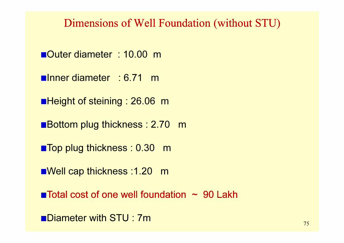
Dimensions Dimensions of of Well Well Foundation (without STU)Foundation (without STU)
Outer diameter : 10.00 m
Inner diameter : 6.71 m
Height of steining : 26.06 m
Bottom plug thickness : 2.70 mBottom plug thickness : 2.70 m
Top plug thickness : 0.30 m
Well cap thickness :1.20 m
Total cost of one well foundation ~ 90 LakhTotal cost of one well foundation ~ 90 Lakh
Diameter with STU : 7m75

Dimensions Dimensions of of Well Well Foundation (with STU)Foundation (with STU)
Outer diameter : 7.00 m
Concrete Quantities (cubic meter):
without STU with STU
Well cap : 188.65 105.16Well cap : 188.65 105.16
Top Plug 10.63 4.88
Stening 2644.74 1568.14
Kerb 375 168.87
76

7777