1 chapter 2: review of important networking concepts magda el zarki dept. of cs uc irvine...
TRANSCRIPT

1
Chapter 2: Review of Important Networking
ConceptsMagda El Zarki
Dept. of CS
UC Irvine
http://www.ics.uci.edu/~magda

Networking Fundamentals
Basic Internet technologies
Basic networking strategies

The Internet: A Collection of Networks

The Internet: A Mesh of Links

What’s the Internet: “nuts and bolts”view
millions of connected computing devices: hosts = end systems running network apps
Home network
Institutional network
Mobile network
Global ISP
Regional ISP
router
PC
server
wirelesslaptop
cellular handheld
wiredlinks
access points
communication links fiber, copper, radio, satellite transmission rate =
bandwidth
routers: forward packets (chunks of data)

What’s the Internet: a service view
communication infrastructure enables distributed applications: Web, VoIP, email, games, e-
commerce, file sharing
communication services provided to apps: reliable data delivery from source to
destination “best effort” (unreliable) data
delivery

The Network Core
mesh of interconnected routers
the fundamental question: how is data transferred through net? circuit switching: dedicated
circuit per call: telephone net packet-switching: data sent thru
net in discrete “chunks”

Network Core: Circuit Switching
End-end resources reserved for “call”
link bandwidth, switch capacity
dedicated resources: no sharing
circuit-like (guaranteed) performance
call setup required

Network Core: Circuit Switching
network resources (e.g., bandwidth) divided into “pieces” dividing link bandwidth into “pieces”
frequency division time division
pieces allocated to calls
resource piece idle if not used by owning call (no sharing)

Network Core: Packet Switching
each end-end data stream divided into packets
user A, B packets share network resources
each packet uses full link bandwidth
resources used as needed

Packet Switching: Statistical Multiplexing
Sequence of A & B packets does not have fixed pattern, bandwidth shared on demand statistical multiplexing.
TDM: each host gets same slot in revolving TDM frame.
A
B
C100 Mb/sEthernet
1.5 Mb/s
D E
statistical multiplexing
queue of packetswaiting for output
link

12
Networking Concepts
Protocol Architecture
Protocol Layers
Encapsulation
IP Addressing

13
A Data Transfer Example: Argon -> Neon

14
DNS: The IP address of
“neon.tcpip-lab.edu” is 128.143.71.21
ARP: What is the MAC address of 128.143.137.1?
Sending a packet from Argon to Neon
DNS: What is the IP address
of “neon.tcpip-lab.edu”?ARP: The MAC address of 128.143.137.1 is 00:e0:f9:23:a8:20
128.143.71.21 is not on my local network.Therefore, I need to send the packet to my
default gateway with address 128.143.137.1
frame
128.143.71.21 is on my local network.Therefore, I can send the packet directly.
ARP: The MAC address of 128.143.137.1 is 00:20:af:03:98:28
ARP: What is the MAC address of 128.143.71.21?
frame

Sequence of events:1.Web client at Argon starts an HTTP Request.
2.Argon contacts its DNS server to translate the domain name “neon.cerf.edu” into IP address “128.143.71.21” and looks up the well-known port number of the web server (port 80).
3.The HTTP client at Argon requests a TCP connection to port 80 at IP address 128.143.71.21.
4.The TCP client at Argon requests its Internet Protocol (IP) to deliver an IP datagram with the connection request to destination 128.143.71.21.
5.The IP process at Argon decides that it cannot deliver the IP datagram directly, and decides to send the IP datagram to its default gateway 128.143.137.1.
6.The Address Resolution Protocol (ARP) at Argon sends an ARP request for the MAC address of IP address 128.143.137.1.
7.The ARP request is broadcast by the Ethernet device driver at Argon to all devices on the Ethernet network.
8.The router with IP address 128.143.137.1 responds with an ARP Response to Argon which includes MAC address 00:e0:f9:23:a8:20.
9.The IP process at Argon asks its Ethernet device driver to send the IP datagram in an Ethernet frame to MAC address 00:e0:f9:23:a8:20.
10.Ethernet device driver at router with MAC address 00:e0:f9:23:a8:20 unpacks the IP datagram, and passes it to its IP process.
11.The IP process at the router decides that it can deliver the IP datagram with destination 128.143.137.21 directly (without the need of additional routers).
12.The Address Resolution Protocol (ARP) at the router sends an ARP request for the MAC address of IP address 128.143.137.21.
13.The ARP request is broadcast by the Ethernet device driver at the router to all devices on the Ethernet network.
14.Neon (which has IP address 128.143.137.21) responds with an ARP Response to the router which includes MAC address 00:20:af:03:98:28.
15.The IP process at the router asks its Ethernet device driver to send the IP datagram in an Ethernet frame to MAC address 00:20:af:03:98:28.
16.The Ethernet device driver at Neon unpacks the IP datagram contained in the Ethernet frame, and passes it to its IP process.
17.The IP process unpacks the TCP connection request contained in the IP datagram and passes it to the TCP server at port 80.
18.The TCP server at port 80 processes the TCP connection request.

16
Communications Architecture
The complexity of the communication task is reduced by using multiple protocol layers:
Each protocol is implemented independently Each protocol is responsible for a specific subtask Protocols are grouped in a hierarchy
A structured set of protocols is called a communications architecture or protocol suite

IP Stack
17
Application
Transport
Network
Link
Physical
DHCP, DIS, DNS, FTP, HTTP, IMAP, RTP, SMTP, SSH, Telnet
TCP, UDP, RSVP
IP, ICMP, IGMP
Ethernet, 802.11, ADSL
copper wires, fibre-optic cable, radio waves

18
Protocol Layers at work
Router

19
Functions of the Layers
Data Link Layer: Service: Reliable transfer of frames over a link
Media Access Control on a LAN Functions: Framing, media access control, error checking
Network Layer: Service: Move packets from source host to destination host Functions: Routing, addressing
Transport Layer: Service: Delivery of data between hosts Functions: Connection establishment/termination, error
control, flow control
Application Layer: Service: Application specific (delivery of email, retrieval of
HTML documents, reliable transfer of file) Functions: Application specific
20
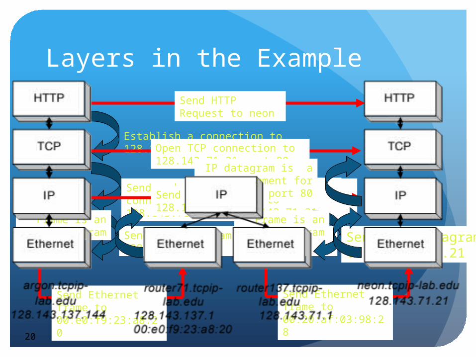
Layers in the Example
Send HTTP Request to neon
Establish a connection to 128.143.71.21 at port 80Open TCP connection to
128.143.71.21 port 80
Send a datagram (which contains a connection request) to 128.143.71.21Send IP datagram to
128.143.71.21
Send the datagram to 128.143.137.1
Send Ethernet frame to 00:e0:f9:23:a8:20
Send Ethernet frame to 00:20:af:03:98:28
Send IP data-gram to 128.143.71.21
Send the datagram to 128.143.7.21
Frame is an IP datagram
Frame is an IP datagram
IP datagram is a TCP segment for port 80

21
Layers and ServicesService provided by TCP to HTTP:
reliable transmission of data over a logical connection
Service provided by IP to TCP: unreliable transmission of IP datagrams across an IP network
Service provided by Ethernet to IP: transmission of a frame across an Ethernet segment
Other services: DNS: translation between domain names and IP addresses
Maps fully qualified domain names (narok.cs.ucl.ac.uk) to their IP addresses (128.16.5.123)
Is a network service
ARP: Translation between IP addresses and MAC addresses Used by IP to find the physical address of a device on a link

22
Assignment of Protocols to Layers

23
Encapsulation and DemultiplexingAs data is moving down the protocol stack, each protocol
is adding layer-specific control information

24
Encapsulation and Demultiplexing
in our Example
Let us look in detail at the Ethernet frame between Argon and the Router, which contains the TCP connection request to Neon.
This is the frame in hexadecimal notation.
00e0 f923 a820 00a0 2471 e444 0800 4500 002c 9d08 4000 8006 8bff 808f 8990 808f 4715 065b 0050 0009 465b 0000 0000 6002 2000 598e 0000 0204 05b4

25
Encapsulation and Demultiplexing

26
Encapsulation and Demultiplexing: Ethernet Header

27
Encapsulation and Demultiplexing: IP Header

28
Encapsulation and Demultiplexing: TCP Header
Option: maximum segment size

29
Different Views of NetworkingApplication (e.g. HTTP) and Transport Layer (e.g. TCP) view of the network
End to End Transmission

30
IP View of the NetworkConcatenation of Networks

31
Ethernet view of the networkSingle Link

Application Layer Protocols
Determine what messages are sent between applicationsMessages defined by syntax and semantics
Various standards for messages, typically set by RFCs (Requests for Comments) hosted by the IETF (Internet Engineering Task Force)

E.G. HTTP Request
If you connect to Host www.cs.ucl.ac.uk at Port 80
And then issue (type!) in ASCII the following message:
GET /staff/A.Steed/ HTTP/1.1
Host: www.cs.ucl.ac.uk
And issues (type) two carriage returns
You get …

HTTP/1.0 200 Document follows
MIME-Version: 1.0
Server: CERN/3.0
Date: Sun, 08 Feb 2009 15:25:18 GMT
Content-Type: text/html
Content-Length: 16150
Last-Modified: Wed, 21 Jan 2009 17:42:00 GMT
<?xml version="1.0" encoding="iso-8859-1"?>
<!DOCTYPE html PUBLIC "-//W3C//DTD XHTML 1.0 Transitional//EN" "http://www.w3.org/TR/xhtml1/DTD/xhtml1-transitional.dtd">
<html xmlns="http://www.w3.org/1999/xhtml" lang="en" dir="ltr">
<head>
<meta http-equiv="Content-Type" content="text/html; charset=iso-8859-1" />
<meta name="keywords" content="A. Steed, Anthony Steed, Department of Computer Science, University College London, virtual environments, virtual reality, computer graphics" />

Application Protocol Descriptions
Often ASCII preamble with binary assets inserted at known or marked positions
Some messages are designed to be carried over a reliable stream and are of unknown length (likely to be over TCP)
Some messages are small and it is not important if they get lost (likely to be over UDP)

Common Application Protocols

E.G. Domain Name Service (DNS)
Maps fully qualified domain names (narok.cs.ucl.ac.uk) to their IP addresses (128.16.5.123)
Is a network service, thus takes time
Time is variable because it’s a hierarchical search
Local DNS caches query responses for a time (e.g. 24 hours)
Otherwise needs to query a up the hierarchy

TRANSPORT LAYER
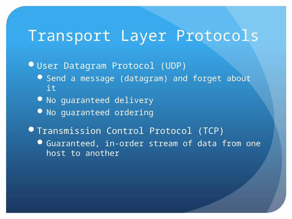
Transport Layer Protocols
User Datagram Protocol (UDP)Send a message (datagram) and forget about itNo guaranteed deliveryNo guaranteed ordering
Transmission Control Protocol (TCP)Guaranteed, in-order stream of data from one host
to another

End to End Principle
Only the sender and receiver understand TCP or UDP (or other higher-level protocols). The routers in the Internet do not.
Port Number
IP Address
Physical Address

Application Protocols and Port Numbers

Transport
Network
Link
Transport
Network
Link
Application Application Application
Source Port = Portxxx
Destination Port = Portyyy
Destination Port = Portzzz
Multiplexing of Users and Sessions
UDPAll hosts on the Internet have an IP address
How does the network know which application program (i.e. process) it needs to reach on a host?
And if it is a shared application, how to distinguish between different users using that same application!
Solution: add a port number to the IP address for use by end-to-end transmission onlyPort numbers are 16 bits numbers, so must lie in the
range 0-65535 Some are reserved, see later
Processes listen for incoming UDP packets
Need to check the packet for consistency

Bits 0 15
16 31
0-31 Source Port Destination Port
32-63
Length Checksum
64+ Data
UDP Segment Layout – Header 8bytes

UDP Checksum• The UDP header field checksum is used to check the integrity
of the packet.• It provides a means of detecting errors in the UDP datagram.• The UDP checksum is calculated using a UDP-pseudo header,
UDP header and the UDP data.• The UDP pseudo header contains the source IP-address, the
destination IP-address, the protocol identifier, and UDP length. • The header field checksum is optional. UDP packets with
wrong checksums are discarded.• The action taken is that the packet is dropped [RFC 768]

UDP Checksum Calculation

TCP In comparison to UDP, TCP offers:
A connection-oriented services with bi-directional (full-duplex) communication
Reliable transmission of messages in each direction Congestion avoidance, using variable rate transmission In order, and non-duplicate delivery of information
Applications place the data bytes into an outgoing buffer
The buffer is streamed in the form of segments to the receiver
At the receiver, the segments are dismantled and the data is stored in a buffer byte by byte, and pushed to the application.

Transport
Network
Link
ApplicationMsg i – X bytes
Msg i-2 Msg i-1…
DataHeader
Buffer
Segment: “x” bytes from buffer

Bits 0 15
16 31
0-31 Source Port Destination Port
32-63 Sequence Number (SN)
64-95 Acknowledgement Number (ACK)
96-127 Data Offset
NotUsed
Flags Receive Window
128-159
Checksum Urgent Pointer
160-191
Options (Optional)
160+ 192+, 224+, etc.
Data
Layout of a TCP Segment – Header 20-40bytes

TCP Checksum• The TCP header field checksum is used to check the integrity
of the segment.• It provides a means of detecting errors in the TCP segment.• The TCP checksum is calculated the same way as the UDP-
checksum is calculated and therefore also considers a TCP-pseudo header.
• The TCP pseudo header contains the source IP-address, the destination IP-address, the protocol identifier, and TCP length. [RFC 793]

TCP Checksum Calculation

TCP is Bi-Directional
Even if, logically, data only flows one way, in order to ensure reliability, we need to send an empty “data” segment back which, by means of fields in the header, tells the transmitter which data has been successfully received (ACK)
The sender must maintain the buffered data until it receives an ACK

Transport
DataHeader
Send Buffer
Receive Buffer
Next Byte Expected from other side
Received Data
Sent Data
Start Byte Start Byte = Start Byte + MSS
(message segment size)
Sequence Number = Start Byte
Acknowledgement Number = Byte Expected
Unsent
Expected in opposite direction
MSS

Header
Sequence Number = M
Transport
Send Buffer
Acknow-ledged
Last Acknowledged
= M
Next Sequence Number
= N
UnsentTo
Send
Data
Transport
Receive Buffer
Received
Expected= N
Just Received
Transport
Send Buffer
Acknowledged
Last Acknowledged
= N
Unsent
Header
Acknowledgement Number = N
An empty data packet, solelyused for ACKs in opp. direction if no data at receiving end.

TCP Reliability
How to detect if something has gone missingA timeoutReturning an ACK repeatedly which indicates the
buffer hasn’t grown (packets discarded because errors occurred or packets lost in network)

Seq # = 100
Data
Host A Host B
Seq # = 200
Data
Seq # = 300
Data
Ack # = 200
Data
Ack # = 200
Data
Seq # = 200
Data
Ack # = 400
Data
Packet Resent on Duplicate ACK
Scenario for “out of” orderdata packet reception
Packet 1
Packet 1 & 3
Packet 1,3,2
Buffer
Cumulative ACK

Seq # = 100
Data
Host A Host B
Seq # = 200
Data
Seq # = 300
Data
Ack # = 200
Data
Ack # = 200
Data
Seq # = 200
Data
Ack # = 300
Data
Packet Resent on Duplicate ACK
Scenario for “in” orderdata packet reception
Packet 1
Packet 1
Packet 1,2
Buffer
Discard out of order packet
Request next “in” order packet

Seq # = 100
Data
Seq # = 200
DataAck # = 200
Data
Seq # = 200
Data
Timeout
Host A Host B
Packet Resent on Timeout
No new data arrival toTrigger repeat ACK

Seq # = 100
Data
Seq # = 200
Data
Seq # = 300
Data
Ack # = 200
Data
Ack # = 400
Data
Ack # = 300
Data
Host A Host B
A Lost ACK Doesn’t Matter
CumulativeACK, 400 ACKsAll previous receptions
Cumulative ACK

TCP FairnessHow does TCP decide when to send packets (with
UDP you call “send”)?
It sends packets with increasing frequency but when theythey are delayed or lost (detected via timeouts or repeated ACKs), it halves its rate
There are LOTS of variants of TCP
Protocols are often tested to see if they are TCP-fair, i.e. if N streams share a network link they get 1/Nth of the bandwidth
UDP is NOT fair, sends data whenever available in application buffer

Time
Ra
te (
byt
es/
s)
10K
20K
30K

Observations
If there is lots of data to send TCP can fill up IP packets, UDP might waste network capacity as it sends as data comes available
There are potentially lots of ACK packets in TCP
TCP is slow to start (connection set-up, 3way handshake), UDP is rapid start
UDP protocols need to play fair when there is congestion

NETWORK LAYER

Network LayerThe Internet is a collection of
machines that understand IP packets
A network routes packets from one host to another through routers
Router
RouteTable
IP Packet
IP Packet

IPv4
In IPv4 addresses are 32 bits in the form 128.16.13.118
They are running out and IPv6 is ready to be deployed

IP: The waist of the hourglass
IP is the waist of the hourglass of the Internet protocol architecture
Multiple higher-layer protocols
Multiple lower-layer protocols
Only one protocol at the network layer.
66
Applications
HTTP FTP SMTP
TCP UDP
IP
Data link layer protocols
Physical layer protocols

The Internet protocol
IP is the highest layer protocol which is implemented at BOTH routers and hosts
67
Application
TCP
IP
Data Link
Application
TCP
IP
NetworkAccess
Application protocol
TCP protocol
IP protocol IP protocol
DataLink
DataLink
IP
DataLink
DataLink
IP
DataLink
DataLink
DataLink
IP protocol
RouterRouter HostHost

IP ServiceDelivery service of IP is minimal
IP provide provides an unreliable connectionless best effort service (also called:“datagram service”).
Unreliable: IP does not make an attempt to recover lost packets Connectionless: Each packet (“datagram”) is handled independently.
IP is not aware that packets between hosts may be sent in a logical sequence
Best effort: IP does not make guarantees on the service (no throughput guarantee, no delay guarantee,…)
Consequences: • Higher layer protocols have to deal with losses or with duplicate packets
• Packets may be delivered out-of-sequence
68

IP Service IP supports the following services:
one-to-one (unicast) one-to-all (broadcast) one-to-several (multicast) one-to-anyone (anycast)
IP multicast also supports a many-to-many service.
IP multicast requires support of other protocols (IGMP, multicast routing)
69
unicastbroadcast
multicast
anycast

Bits 0 15
16 31
0-31 Version
Header
Length
Type of Service
Total Length
32-63 Identification Flags
Fragment Offset
64-95 Time to Live
Protocol Header Checksum
96-127 Data Offset
NotUsed
Flags Receive Window
128-159
Source Address
Destination Address
160-191
Options (Optional)
Bits 0 15
16 31
0-31 Version
Header
Length
Type of Service
Total Length
32-63 Identification Flags
Fragment Offset
64-95 Time to Live
Protocol Header Checksum
96-127 Source Address
128-159
Destination Address
160-191
Options (Optional)
160+ 192+, 224+, etc.
Data
IP Packet Format

Protocol Types
This is necessary to tell the receiver what the IP packet contains. E.G.:
1: Internet Control Message Protocol (ICMP)2: Internet Group Management Protocol (IGMP)6: Transmission Control Protocol (TCP)17: User Datagram Protocol (UDP)89: Open Shortest Path First (OSPF)

IP Addresses
Structure of an IP address
Subnetting
Classless Inter Domain Routing (CIDR)

IP Addresses

IP Addresses

What is an IP Address?
An IP address is a unique global address for a network interface. Each device on the Internet has a network interface. Some
devices may have more than one! Example: ??? Each device belongs to a domain. A
An IP address: is a 32 bit long identifier encodes a network number (network prefix) and a host
number

Dotted Decimal NotationIP addresses are written in a so-called dotted decimal
notation
Each byte is identified by a decimal number in the range [0..255]:
1000111110000000 10001001 10010000
1st Byte
= 128
2nd Byte
= 143
3rd Byte
= 137
4th Byte
= 144
128.143.137.144

The network prefix identifies a network and the host number identifies a specific host (actually, interface on the network).
How do we know how long the network prefix is? The network prefix is implicitly defined (class-based
addressing) The network prefix is indicated by a netmask.
Network prefix and Host number
network prefix host number

Example: ellington.cs.virginia.edu
Network id is: 128.143.0.0
Host number is: 137.144
Network mask is: 255.255.0.0 or ffff0000
Prefix notation: 128.143.137.144/16
Network prefix is 16 bits long
Example
128.143 137.144

Subnetting and Classless Inter Domain Routing (CIDR) Since the networks of some organizations grow large, network
operators can decide to subdivide the network into smaller subnetworks and assign each subnetwork its own network address.
This process is known as subnetting.
Subnetting is done by allocating some of the leading bits of the host number to indicate a subnet number. With subnetting, the network prefix and the subnet number make up an
extended network prefix. The extended prefix can be expressed in terms of a subnetmask or,
using CIDR notation, by adding the length of the extended subnetmask after the IP address.
For example, for Argon, the first byte of the host number (the third byte of the IP address) is used to denote the subnet number. 128.143.0.0/16 is the IP address of the network (network prefix /16), 128.143.137.0/24 is the IP address of the subnet, 128.143.137.144/32 is the IP address of the host, and 255.255.255.0 is the subnetmask of the host (or subnet prefix /24))

Basic Idea of SubnettingSplit the host number portion of an IP address into a subnet number and a (smaller) host number.
Result is a 3-layer hierarchy
Then: Subnets can be freely assigned within the organization Internally, subnets are treated as separate networks Subnet structure is not visible outside the organization
network prefix host number
subnet numbernetwork prefix host number
extended network prefix

Subnetting Example: Argon

Network without subnets

Same Network with Subnets

Same network with different subnetmasks

Each layer-2 network (Ethernet segment, FDDI segment) is allocated a subnet address when connected to a router.
Typical Addressing Plan for an Organization that uses subnetting
128.143.0.0/16
GatewayRouter
R
R
R

CIDR - Classless Inter Domain Routing
Key Concept: The length of the network id (prefix) in the IP addresses is kept arbitrary: 32 - 1
Routers advertise not only reachable IP addresses, but ALSO the length of the prefix for each IP address

CIDR Example
CIDR notation of a network address:
192.0.2.0/18 "18" says that the first 18 bits are the network part of the
address (and 14 bits are available for specific host addresses)
The network part is called the prefix

CIDR and Address assignments
Backbone ISPs obtain large block of IP addresses space and then reallocate portions of their address blocks to their customers.
Example:
Assume that an ISP owns the address block 206.0.64.0/18, which represents 16,384 (232-18=214) IP addresses
Suppose a client requires a network that can support 800 host addresses
Assign a /22 prefix (512=29<800<1024=210 -> 32-10=22), i.e., 206.0.68.0/22 gives a block of 1,024 (210) IP addresses.

CIDR and Routing Information
206.0.64.0/18204.188.0.0/15209.88.232.0/21Internet
Backbone
ISP X owns:
Company X :
206.0.68.0/22
ISP y :
209.88.237.0/24
Organization z1 :
209.88.237.192/26Organization z2 :
209.88.237.0/26

CIDR and Routing Information
206.0.64.0/18204.188.0.0/15209.88.232.0/21
Internet Backbone
ISP X owns:
Company X :
206.0.68.0/22
ISP y :
209.88.237.0/24
Organization z1 :
209.88.237.192/26Organization z2 :
209.88.237.0/26
Backbone sends everything which matches the prefixes 206.0.64.0/18, 204.188.0.0/15, 209.88.232.0/21 to ISP X.
ISP X sends everything which matches the prefix: 206.0.68.0/22 to Company X,209.88.237.0/24 to ISP y
Backbone routers do not know anything about Company X, ISP Y, or Organizations z1, z2.
ISP X does not know about Organizations z1, z2.
ISP y sends everything which matches the prefix: 209.88.237.192/26 to Organizations z1 209.88.237.0/26 to Organizations z2

IP Address AllocationOur experience is that for a specific device interface,
we either need to: Set IP address manually Get an IP address automatically using Dynamic Host
Control Protocol (DHCP)
DHCP is actually network service protocol, it passes out IP addresses on a subnet, based on a pool of available addresses assigned by network administrator.
Host sends a request to local DHCP for an available IP address,
Each IP address has a lease that needs to be renewed, done automatically so long as device is active


LINK AND PHYSICAL LAYER

Link and Physical LayerThe one we all have experience with is Ethernet, either
wired or wireless
Link Layer deals with communication over a single network segment which could be a point to point link, a radio channel a coax cable, or ……..
To deliver packets we need to have a mapping between the MAC address of the Ethernet adapter (physical device address) and the IP address (network address)
Use Address Resolution Protocol (ARP)

95
Protocol Layers at work
Router

96
Address Translation with ARP
ARP Request: Argon broadcasts an ARP request to all stations on the network: “What is the hardware address of Router with IP address 128.143.137.1?”
Argon128.143.137.144
00:a0:24:71:e4:44
Router137128.143.137.1
00:e0:f9:23:a8:20
ARP Request:What is the MAC addressof 128.143.71.1?
Arp Request:What is MAC address of 128.143.137.1

97
Address Translation with ARP
ARP Reply: Router 137 responds with an ARP Reply which contains the hardware address
Argon128.143.137.144
00:a0:24:71:e4:44
Router137128.143.137.1
00:e0:f9:23:a8:20
ARP Reply:The MAC address of 128.143.71.1is 00:e0:f9:23:a8:20
Arp Reply:MAC address of 128.143.137.1Is 00:e0:f9:23:a8:20

Bits 0 15
16 31
0-31 Version
Header
Length
Type of Service
Total Length
32-63 Identification Flags
Fragment Offset
64-95 Time to Live
Protocol Header Checksum
96-127 Data Offset
NotUsed
Flags Receive Window
Bits 0 15
16 31
0-31 Destination MAC Address (6bytes) …
32-63 … Destination MAC Address
Source MAC Address (6bytes)…
64-95 …Source MAC Address
96-127 Protocol Type Data
… Data
… CRC Checksum
Link Layer Frame Format

Basic Networking Strategies

Architectures
Peer to Peer
Client/Server
Hybrid
100

Consider Just Two Machines
101
• What is the relationship between them?• Peers?• Master/slave? Client/server?• Does one have data the other one does not?

Peer to Peer with Two Clients
Need to decide separation of responsibilitiesE.G. Each client simulates one player’s actions
Need to communicate sufficient information to the other that they can get both get the same state
Assumes that they have the same information other than real-time input
Can be achieved simply with sending input to each other

Doom ClientA
ReadInput
Rendering
ReceiveInput
Simulate
Doom ClientC
ReadInput
Rendering
ReceiveInput
Simulate
For Example DOOM - P2P

Master/Slave with Two Clients
One process calculates results of input
Other just waits for rendering information
Necessary if simulation is non-deterministic (output unknown, one has to decide)

Slave
ReadInput
Rendering
Master
ReadInput
Rendering
ReceiveInput
Simulate
For Example – Thin Client/Server

More Than two Clients
The same issues exist:Who is responsible?Who has the necessary data to evolve the state?Who can be trusted to evolve the state?

Peer to Peer Architecture
107
Client
Client
ClientClient
Client
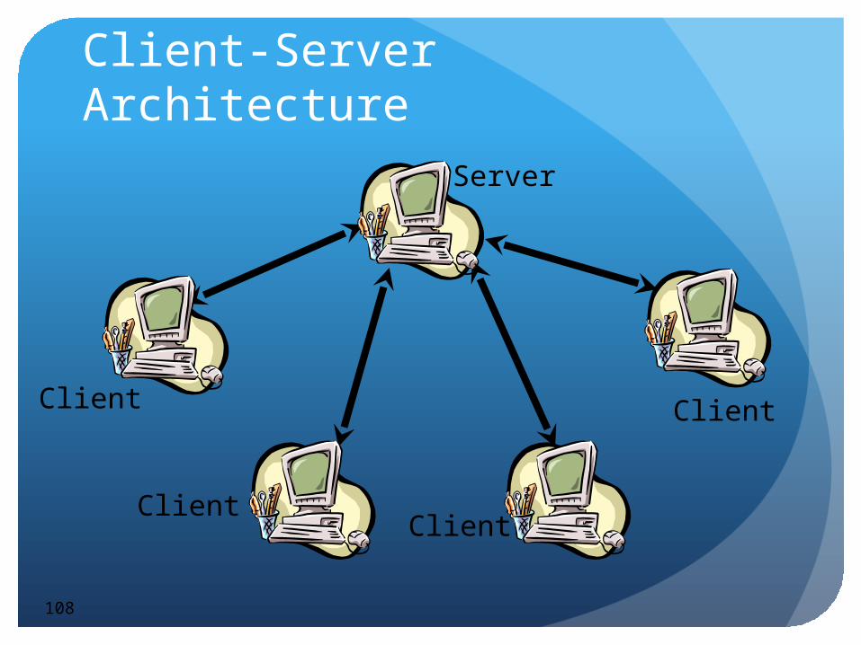
Client-Server Architecture
108
Server
Client
ClientClient
Client

Implications
Peer to PeerData need to be sent multiple times on the network
links might vary in bandwidth & latencyClients need to manage multiple connections
Client ServerThe Server is a bottleneckClients manage one connectionServer can have privileged data, and can probably
be trustedLatency is higherSynchronization is easy

Hybrid Architectures
110
• Multiple servers serving different regions• Multiple service types & service layers
Server pool

Summary

Which Protocol to Use?
If there is an application layer protocol that is appropriate use that!
UDPGood for fast changing data, and initial start updateGood for position information
TCPGood for reliable data, and bulk data transferGood for data assets and critical information such as
score

Which Protocol to Use?
Some people implement “reliability-lite” on top of UDP
Other platforms mix UDP & TCPThere are many catches with this
Many platforms support application layer protocols such as HTTP or FTP for bulk asset transfer

Conclusions
NVEs & NGs have a long history, but it is in the last 10 years that they have really taken off
The Internet is a best effort network where applications need to deal with latency & loss
There are various architectures that support NVEs & NGs