1 communications laboratory china delegation presentation selecting digital television for australia...
TRANSCRIPT

1
Communications Laboratory China Delegation PresentationCommunications Laboratory China Delegation Presentation
Selecting Digital Selecting Digital Television for Television for
AustraliaAustraliaPresentation by: Neil PickfordPresentation by: Neil Pickford
www.commslab.gov.au/lab/info/digtvwww.commslab.gov.au/lab/info/digtv

2
Digital TelevisionDigital Television
Why digital?Why digital? Noise free picturesNoise free pictures Higher resolution imagesHigher resolution images
Widescreen / HDTVWidescreen / HDTV No ghostingNo ghosting Multi-channel soundMulti-channel sound Other services.Other services.

3
Broad Objectives of DTBBroad Objectives of DTB Overcome limitations of the existing Overcome limitations of the existing
analog television systemanalog television system Improved picture Improved picture
High quality (no interference)High quality (no interference) Resolution (HDTV)Resolution (HDTV) Format (16:9)Format (16:9)
Enhanced Audio servicesEnhanced Audio services Data capacity available for other value added Data capacity available for other value added
servicesservices
4
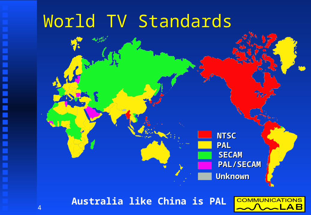
World TV StandardsWorld TV Standards
Australia like China is PAL
NTSCNTSCPALPALSECAMSECAMPAL/SECAMPAL/SECAM
UnknownUnknown

5
Transmission Bandwidth - VHFTransmission Bandwidth - VHF
Australia is 7 MHz, China is 8 MHz
6 MHz6 MHz7 MHz7 MHz8 MHz8 MHzNot in UseNot in Use
6
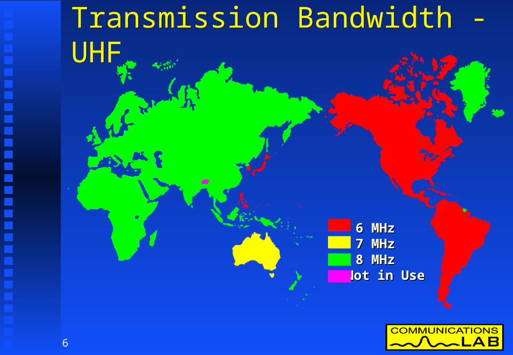
Transmission Bandwidth - UHFTransmission Bandwidth - UHF
6 MHz6 MHz7 MHz7 MHz8 MHz8 MHzNot in UseNot in Use
7
The Australian Broadcasting Environment
The Australian Broadcasting Environment
The unique broadcasting environment of The unique broadcasting environment of Australia has had a major influence on the way Australia has had a major influence on the way we have looked at digital television.we have looked at digital television.
What are the main defining aspects of the What are the main defining aspects of the Australian television environment?Australian television environment?
8
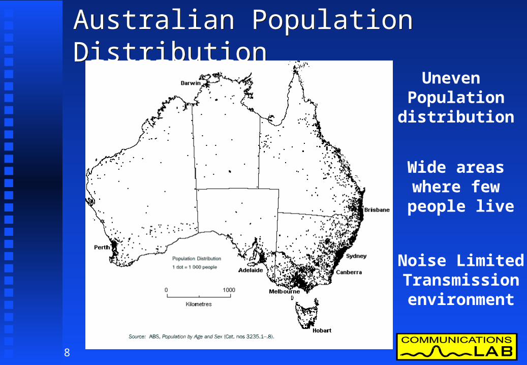
Australian Population DistributionAustralian Population Distribution
Uneven Populationdistribution
Wide areas where few people live
Noise LimitedTransmissionenvironment

9
Free To Air Television (FTA)Free To Air Television (FTA)
Important part of Australian entertainmentImportant part of Australian entertainment
Majority of Australian audience is watchingMajority of Australian audience is watching
No television receiving licencesNo television receiving licences
National broadcasters funded from taxationNational broadcasters funded from taxation
10
Free To Air Broadcasters (Cont)Free To Air Broadcasters (Cont)
Total of 5 FTA broadcastersTotal of 5 FTA broadcasters 2 national broadcasters (ABC & SBS)2 national broadcasters (ABC & SBS) 3 commercial broadcasters 3 commercial broadcasters
(Seven, Nine & TEN networks) (Seven, Nine & TEN networks)
Commercial broadcasters have affiliated regional Commercial broadcasters have affiliated regional networks similar to US industrynetworks similar to US industry
Limits on ownership of media outlets (including Limits on ownership of media outlets (including television) imposed by governmenttelevision) imposed by government

11
Pay TV - Cable, MDS & SatellitePay TV - Cable, MDS & Satellite
Only a small business in AustraliaOnly a small business in Australia Less then 400,000 subscribersLess then 400,000 subscribers Less than 7% of householdsLess than 7% of households
Indoor receptionIndoor reception Around 30% of Australians watch FTA using Around 30% of Australians watch FTA using
indoor antennasindoor antennas

12
Program Quality Vs QuantityProgram Quality Vs Quantity
Australians have a low number of Australians have a low number of
available television channelsavailable television channels
Television program budget is spread between Television program budget is spread between
fewer programsfewer programs
Australians used to watching high quality Australians used to watching high quality
programming at high technical quality.programming at high technical quality.

13
Australian Television TransmittersAustralian Television Transmitters
Use moderate power levelsUse moderate power levels TypicallyTypically
VHF 100 kW EIRPVHF 100 kW EIRP UHF 1 MW EIRPUHF 1 MW EIRP
Common antenna & feeder systemsCommon antenna & feeder systems Most use combiner technologyMost use combiner technology 10 rebroadcast sites for each main Tx10 rebroadcast sites for each main Tx Many of these are frequency transposersMany of these are frequency transposers

14
Receiver BandwidthReceiver Bandwidth
Australia has 7 MHz channels at VHF & UHFAustralia has 7 MHz channels at VHF & UHF Receivers from Europe or America will require Receivers from Europe or America will require
modifications to operate in the 7 MHz domain.modifications to operate in the 7 MHz domain. VHF tuner VHF tuner 7 MHz IF filter7 MHz IF filter Synthesizer programmingSynthesizer programming Control software modificationsControl software modifications
15
Australian Television EnvironmentAustralian Television Environment
We have a unique television environmentWe have a unique television environment This is why we have been keen to investigate This is why we have been keen to investigate
digital transmission technologydigital transmission technology
Australia has been an early implementer before.Australia has been an early implementer before. B-MAC was introduced for remote area B-MAC was introduced for remote area
broadcasting in 1985.broadcasting in 1985. Australia is leading again with HDTV plans.Australia is leading again with HDTV plans.

16
Digital TV Systems DevelopmentDigital TV Systems Development
Australia has been following Digital TV & HDTVAustralia has been following Digital TV & HDTV Europeans Europeans - Digital SDTV - Digital SDTV
- 8 MHz on UHF- 8 MHz on UHF- DVB-T (COFDM)- DVB-T (COFDM)
AmericansAmericans - Digital HDTV - Digital HDTV - 6 MHz VHF/UHF- 6 MHz VHF/UHF- ATSC (8-VSB)- ATSC (8-VSB)
Japanese Japanese - Integrated Broadcasting- Integrated Broadcasting- ISDB (BST-OFDM)- ISDB (BST-OFDM)

17
Australia’s Involvement in DTVAustralia’s Involvement in DTV
Testing MPEG 1 & 2 SW profiles in early 90sTesting MPEG 1 & 2 SW profiles in early 90s ITU-R study groups 10 & 11ITU-R study groups 10 & 11 Initiated formation of ITU-R task group 11/3Initiated formation of ITU-R task group 11/3 TG 11/3 fostered convergence of systemsTG 11/3 fostered convergence of systems
Source coding the sameSource coding the same Modulation differentModulation different
1993 ABA inquiry into planning & system 1993 ABA inquiry into planning & system implications of DTTBimplications of DTTB
1997 recommended HDTV1997 recommended HDTV

18
HDTV - Why Do We Want It?HDTV - Why Do We Want It?
HDTV has been coming for a long time & HDTV has been coming for a long time & Australia has been following it for a long timeAustralia has been following it for a long time
Australia believes Australia believes HDTVHDTV will be the will be the FUTUREFUTURE television viewing format.television viewing format.
Any system we implement NOW must cater for Any system we implement NOW must cater for HDTV in the FUTUREHDTV in the FUTURE
If HDTV is not designed in at the outset then you If HDTV is not designed in at the outset then you will be constrained by the lowest common will be constrained by the lowest common denominator in the TV market.denominator in the TV market.
19
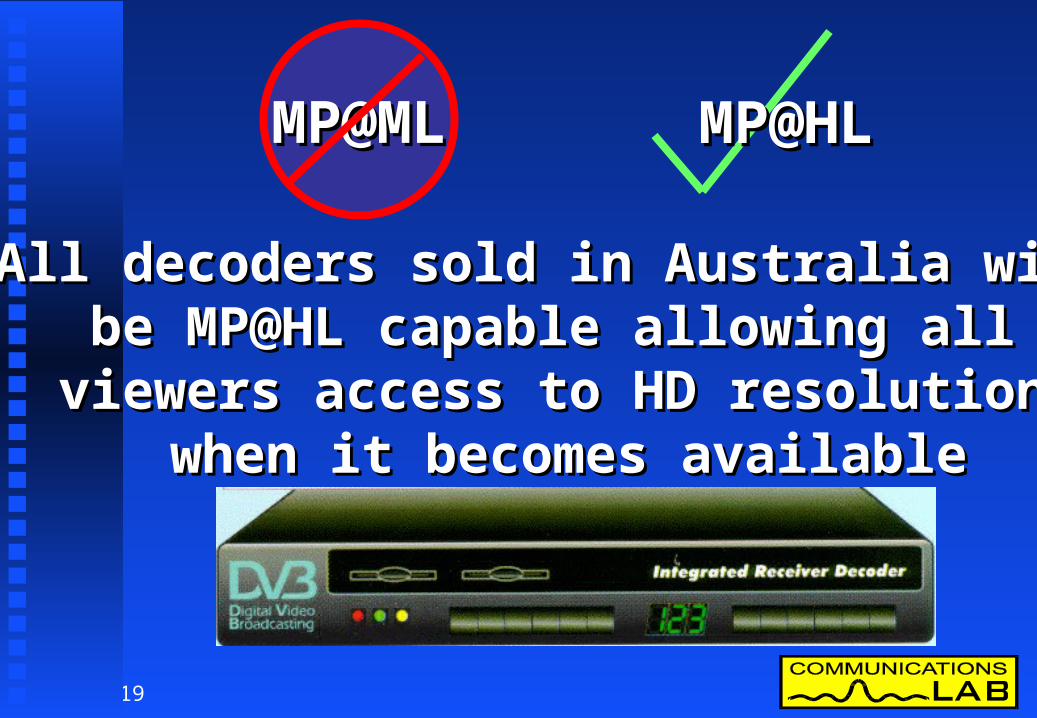
All decoders sold in Australia will All decoders sold in Australia will be MP@HL capable allowing all be MP@HL capable allowing all viewers access to HD resolution viewers access to HD resolution
when it becomes availablewhen it becomes available
MP@MLMP@ML MP@HLMP@HL

20
MPEG-2 - Formats ML & HLMPEG-2 - Formats ML & HL MPEG-2 defines profiles & levelsMPEG-2 defines profiles & levels
They describe sets of compression toolsThey describe sets of compression tools DTTB uses main profile.DTTB uses main profile. With a choice of levelsWith a choice of levels
Higher levels include lower levelsHigher levels include lower levels
LevelLevel Max ResolutionMax Resolution FormatFormatLow level (LL)Low level (LL) 360 by 288360 by 288 SIFSIFMain level (ML)Main level (ML) 720 by 576720 by 576 SDTV SDTV High level (HL)High level (HL) 1920 by 11521920 by 1152 HDTVHDTV

21
FACTS - Specialists GroupFACTS - Specialists Group
Federation of Australian commercial television Federation of Australian commercial television stations (FACTS) have formed the advanced stations (FACTS) have formed the advanced television specialists grouptelevision specialists group Investigate all aspects of Investigate all aspects of
future television technologyfuture television technology Digital TV - transmission & distributionDigital TV - transmission & distribution HDTV technologyHDTV technology Digital encoding, interchange & Digital encoding, interchange &
distribution for current SDTVdistribution for current SDTV

22
The Benefits of Digital TVThe Benefits of Digital TV
More predictable/reliable receptionMore predictable/reliable reception A change in aspect ratio of pictures 4:3 A change in aspect ratio of pictures 4:3 16:9 16:9 Higher resolution pictures –Higher resolution pictures –
high definition for those with HD displayshigh definition for those with HD displays Multichannel digital surround sound technology.Multichannel digital surround sound technology. More capacity for additional servicesMore capacity for additional services
The user will see the following benefits.The user will see the following benefits.

23
Digital TV Transmission Technology
Digital TV Transmission Technology
The transmission The transmission system is asystem is a “data pipe” “data pipe”
Transports data rates Transports data rates of around 20 Mb/sof around 20 Mb/s
Transports data in Transports data in individual containers individual containers called packetscalled packets

24
DTTB Transmission SystemsDTTB Transmission Systems
3 systems are being developed at present.3 systems are being developed at present.
USAUSA ATSC ATSC 8-VSB8-VSB HDTVHDTV
EuropeEurope DVB-T DVB-T COFDMCOFDM SDTVSDTV
JapanJapan ISDBISDB Band Segmented Band Segmented OFDMOFDM

25
Only European and American Only European and American
systems are sufficiently developed systems are sufficiently developed
to allow implementation by 2001to allow implementation by 2001
26
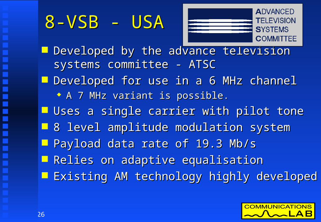
8-VSB - USA8-VSB - USA Developed by the advance television systems committee Developed by the advance television systems committee
- ATSC- ATSC Developed for use in a 6 MHz channelDeveloped for use in a 6 MHz channel
A 7 MHz variant is possible.A 7 MHz variant is possible.
Uses a single carrier with pilot toneUses a single carrier with pilot tone 8 level amplitude modulation system8 level amplitude modulation system Payload data rate of 19.3 Mb/sPayload data rate of 19.3 Mb/s Relies on adaptive equalisationRelies on adaptive equalisation Existing AM technology highly developedExisting AM technology highly developed

27
COFDM - EuropeCOFDM - Europe Developed by the digital video Developed by the digital video
broadcasting project group - DVBbroadcasting project group - DVB Uses similar technology to DRBUses similar technology to DRB Uses 1705 or 6817 carriersUses 1705 or 6817 carriers Variable carrier modulation types are defined allowing data Variable carrier modulation types are defined allowing data
rates of 5-27 Mb/s in 7 MHzrates of 5-27 Mb/s in 7 MHz Developed for 8 MHz channelsDeveloped for 8 MHz channels
A 7 MHz variant has been produced and testedA 7 MHz variant has been produced and tested
Can use Single Frequency Networks - SFNsCan use Single Frequency Networks - SFNs New technology with scope for continued improvement & New technology with scope for continued improvement &
developmentdevelopment

28
ISDB - JapanISDB - Japan Japanese are developing integrated services digital Japanese are developing integrated services digital
broadcasting (ISDB)broadcasting (ISDB) System integrates all forms of broadcasting System integrates all forms of broadcasting
services into one common data channel which can services into one common data channel which can be passed by satellite, cable or terrestrial delivery be passed by satellite, cable or terrestrial delivery systemssystems
Video servicesVideo services Sound servicesSound services Bulk data servicesBulk data services Interactive data servicesInteractive data services

29
ISDB - ConceptISDB - Concept
Proposed to use band segmented transmission - Proposed to use band segmented transmission - orthogonal frequency division multiplex orthogonal frequency division multiplex (BST-OFDM)(BST-OFDM)
30
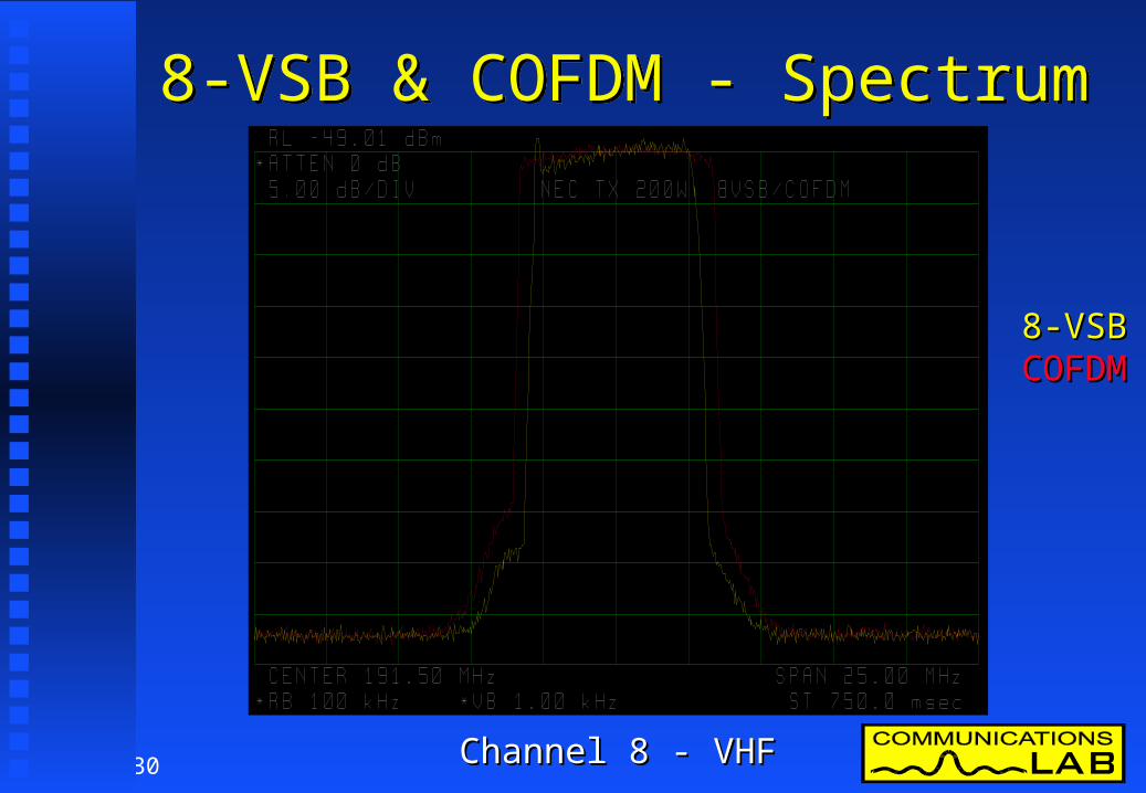
8-VSB & COFDM - Spectrum8-VSB & COFDM - Spectrum
8-VSB8-VSBCOFDMCOFDM
Channel 8 - VHFChannel 8 - VHF
31
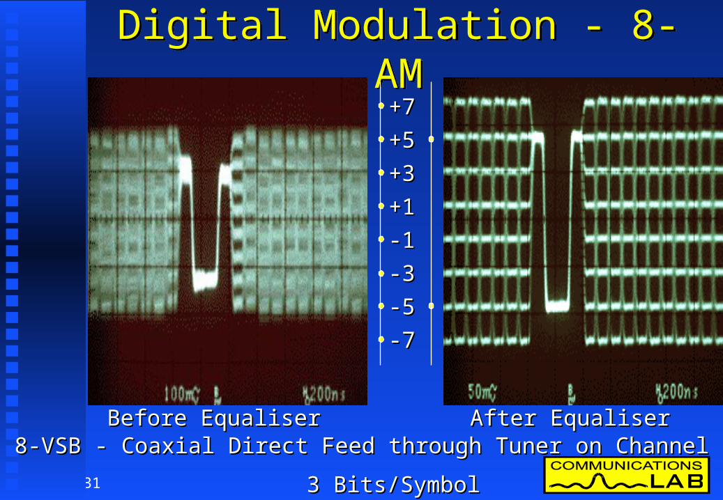
Digital Modulation - 8-AMDigital Modulation - 8-AM
3 Bits/Symbol3 Bits/Symbol
+7+7
-5-5
-3-3
-1-1
+1+1
+3+3
+5+5
-7-7
8-VSB - Coaxial Direct Feed through Tuner on Channel 8 VHF8-VSB - Coaxial Direct Feed through Tuner on Channel 8 VHFBefore EqualiserBefore Equaliser After EqualiserAfter Equaliser

32
COFDM - Orthogonal CarriersCOFDM - Orthogonal Carriers
FrequencyFrequency

33
Spectrum of COFDM DTTBSpectrum of COFDM DTTB
6.67 MHz in 7 MHz Channel6.67 MHz in 7 MHz Channel
AlmostAlmostRectangularRectangular
ShapeShape
1705 or 6817 Carriers1705 or 6817 Carriers
Carrier SpacingCarrier Spacing2k Mode 3.91 kHz2k Mode 3.91 kHz8k Mode 0.98 kHz8k Mode 0.98 kHz
34
7 MHz Theoretical DVB Transmission signal spectrum
-60
-50
-40
-30
-20
-10
0
-8 -7 -6 -5 -4 -3 -2 -1 0 1 2 3 4 5 6 7 8
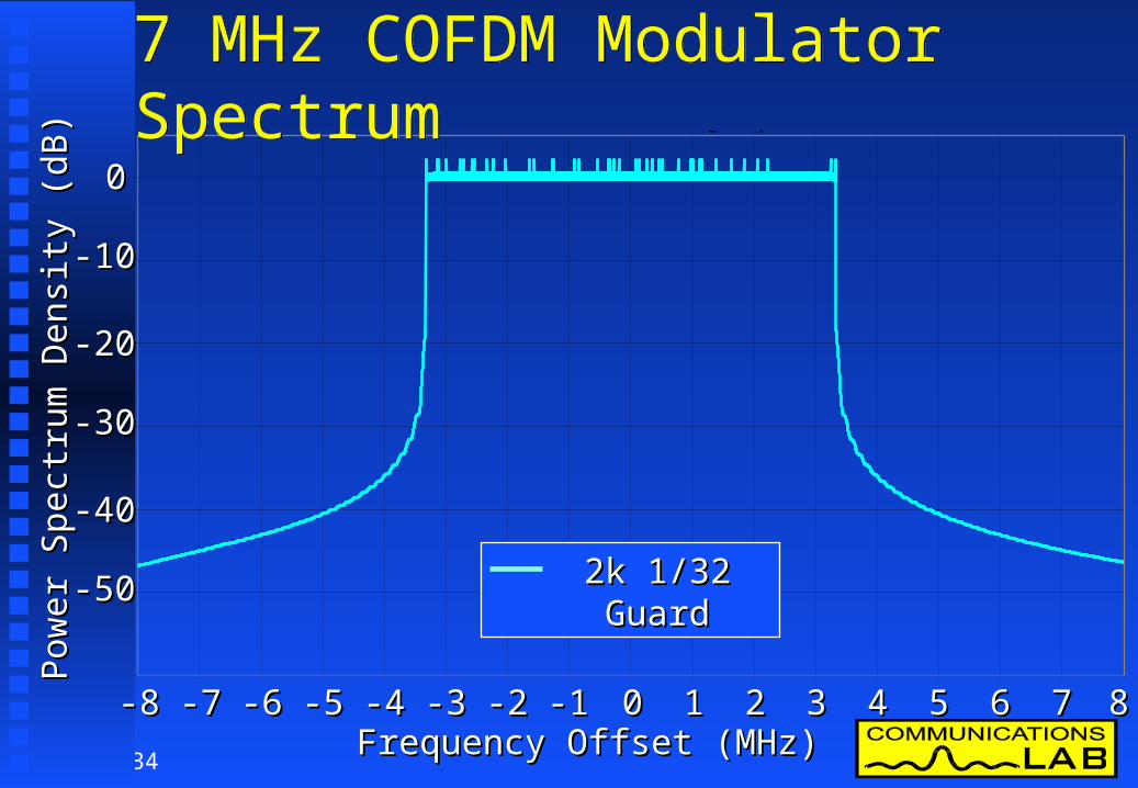
7 MHz COFDM Modulator Spectrum7 MHz COFDM Modulator Spectrum
2k 1/32 Guard2k 1/32 Guard
00
-10-10
-20-20
-30-30
-40-40
-50-50
00-1-1-2-2-3-3-4-4-5-5-6-6-7-7-8-8 11 22 33 44 55 66 77 88Frequency Offset (MHz)Frequency Offset (MHz)
Pow
er S
pect
rum
Den
sity
(dB
)P
ower
Spe
ctru
m D
ensi
ty (
dB)

35
7 MHz Theoretical DVB Transmission signal spectrum
-60
-50
-40
-30
-20
-10
0
-8 -7 -6 -5 -4 -3 -2 -1 0 1 2 3 4 5 6 7 8
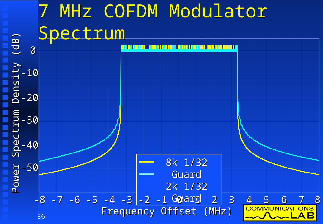
7 MHz COFDM Modulator Spectrum7 MHz COFDM Modulator Spectrum
8k 1/32 Guard8k 1/32 Guard
00
-10-10
-20-20
-30-30
-40-40
-50-50
00-1-1-2-2-3-3-4-4-5-5-6-6-7-7-8-8 11 22 33 44 55 66 77 88Frequency Offset (MHz)Frequency Offset (MHz)
Pow
er S
pect
rum
Den
sity
(dB
)P
ower
Spe
ctru
m D
ensi
ty (
dB)
36
7 MHz Theoretical DVB Transmission signal spectrum
-60
-50
-40
-30
-20
-10
0
-8 -7 -6 -5 -4 -3 -2 -1 0 1 2 3 4 5 6 7 8
7 MHz COFDM Modulator Spectrum7 MHz COFDM Modulator Spectrum
8k 1/32 Guard8k 1/32 Guard2k 1/32 Guard2k 1/32 Guard
00
-10-10
-20-20
-30-30
-40-40
-50-50
00-1-1-2-2-3-3-4-4-5-5-6-6-7-7-8-8 11 22 33 44 55 66 77 88Frequency Offset (MHz)Frequency Offset (MHz)
Pow
er S
pect
rum
Den
sity
(dB
)P
ower
Spe
ctru
m D
ensi
ty (
dB)
37
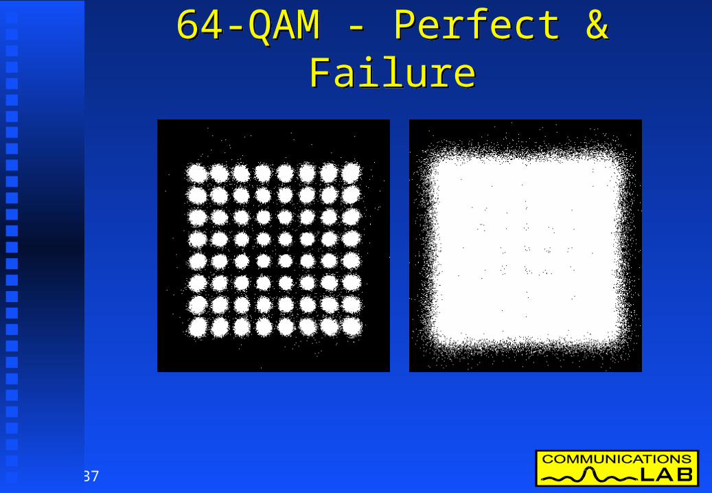
64-QAM - Perfect & Failure64-QAM - Perfect & Failure
38
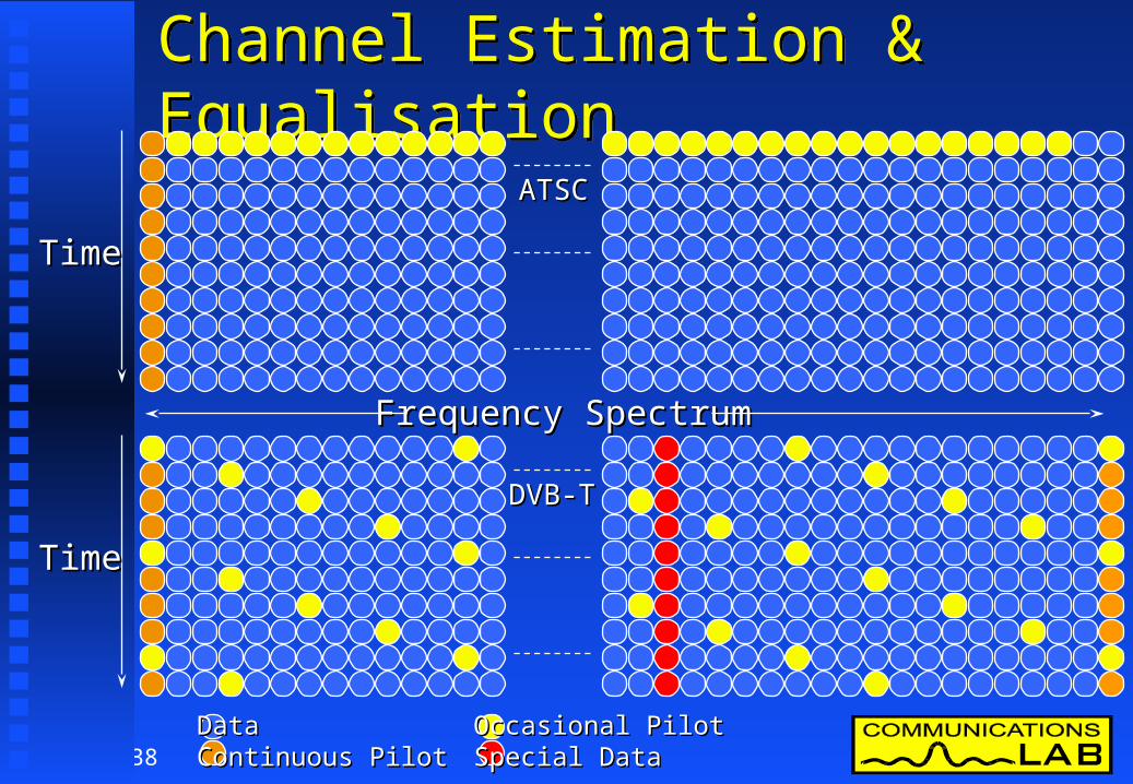
Channel Estimation & EqualisationChannel Estimation & Equalisation
TimeTime
TimeTime
ATSCATSC
DVB-TDVB-T
Data Data Continuous PilotContinuous Pilot
Occasional PilotOccasional PilotSpecial DataSpecial Data
Frequency SpectrumFrequency Spectrum

39

40
COFDM - Commercial ReceiverCOFDM - Commercial Receiver News Data Systems - System 3000News Data Systems - System 3000
41
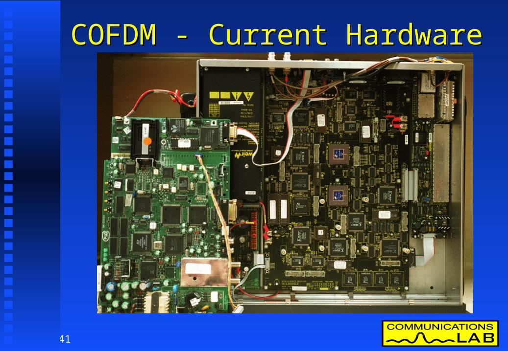
COFDM - Current HardwareCOFDM - Current Hardware

42
Australian DTTB System EvaluationAustralian DTTB System Evaluation
Australia has a Unique Broadcasting Australia has a Unique Broadcasting Environment.Environment.
Australian TV channels are 7 MHz wideAustralian TV channels are 7 MHz wideon both VHF & UHFon both VHF & UHF
We use PAL-B with sound system GWe use PAL-B with sound system G Any DTTB system will need to be configured to Any DTTB system will need to be configured to
suit the existing television broadcasting suit the existing television broadcasting environment during the transition periodenvironment during the transition period
Digital has to Fit in with PAL-BDigital has to Fit in with PAL-B

43
Digital Has to Fit In With PALDigital Has to Fit In With PAL World TV channel bandwidths varyWorld TV channel bandwidths vary
USA / Japan 6 MHzUSA / Japan 6 MHz
Australian 7 MHzAustralian 7 MHz
Europeans 8 MHzEuropeans 8 MHz
Affects:-Affects:- tuning, filtering, interference tuning, filtering, interference & system performance& system performance2828
2828
2828
3030
30302929
2929
3131
3131 3232 3333 3434 3535
3535
35353434
34343333
3333
3232
3232
313130302929

44
Digital Has to Fit In With PALDigital Has to Fit In With PAL
Digital television system development is Digital television system development is focused in Europe & USAfocused in Europe & USA The systems standards are designed to meet the needs The systems standards are designed to meet the needs
of the developersof the developers They focus on their countries needs firstThey focus on their countries needs first Australian input is through standards organisations Australian input is through standards organisations
such as the ITU-R, DVB & ATSCsuch as the ITU-R, DVB & ATSC Australia is looking for a system to satisfy its OWN Australia is looking for a system to satisfy its OWN
Future Broadcasting NeedsFuture Broadcasting Needs

45
Channel SpacingChannel Spacing Existing analog TV channels are spaced so they do not interfere with Existing analog TV channels are spaced so they do not interfere with
each other.each other. Gap between PAL TV servicesGap between PAL TV services
VHF 1 channelVHF 1 channel UHF 2 channelsUHF 2 channels
Digital TV can make use of these gapsDigital TV can make use of these gaps
Ch 7Ch 7 Ch 8Ch 8 Ch 9Ch 9Ch 6Ch 6 Ch 9ACh 9A
VHF Television SpectrumVHF Television Spectrum
TabooTaboo TabooTaboo TabooTaboo
46
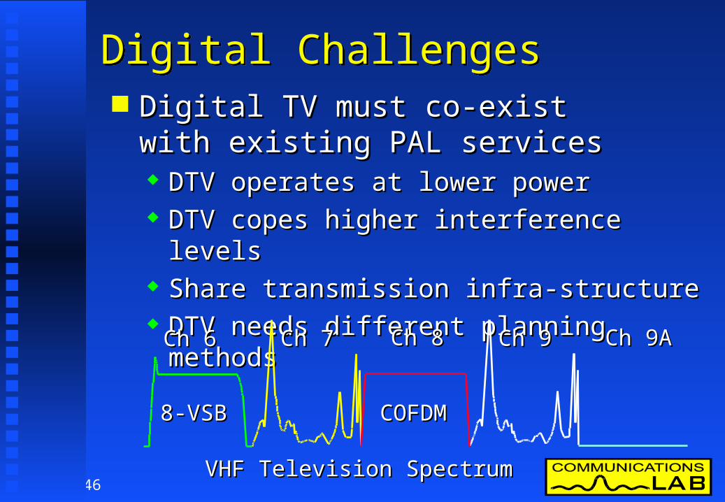
Digital ChallengesDigital Challenges Digital TV must co-exist Digital TV must co-exist
with existing PAL serviceswith existing PAL services DTV operates at lower powerDTV operates at lower power DTV copes higher interference levelsDTV copes higher interference levels Share transmission infra-structureShare transmission infra-structure DTV needs different planning methods DTV needs different planning methods
Ch 7Ch 7 Ch 8Ch 8 Ch 9Ch 9Ch 6Ch 6 Ch 9ACh 9A
VHF Television SpectrumVHF Television Spectrum
8-VSB8-VSB COFDMCOFDM
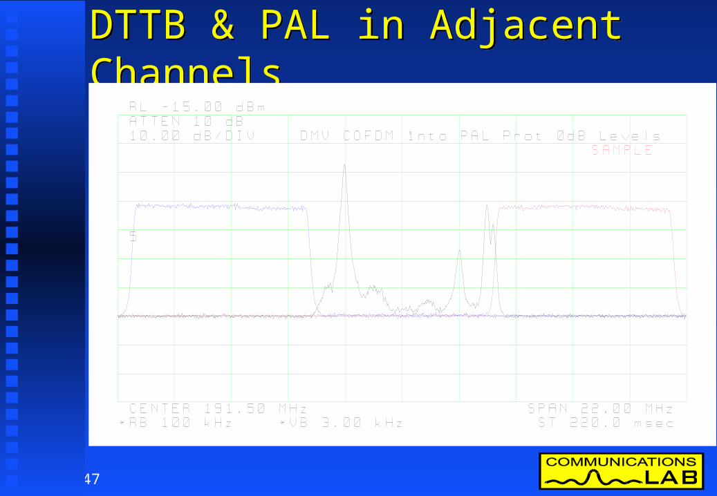
47
DTTB & PAL in Adjacent ChannelsDTTB & PAL in Adjacent Channels
48
Digital Service Area PlanningDigital Service Area Planning
Analog TV has a slow gradual failureAnalog TV has a slow gradual failure Existing PAL service was planned for:Existing PAL service was planned for:
50 % availability at 50 % availability at 50 % of locations50 % of locations
Digital TV has a “cliff edge” failureDigital TV has a “cliff edge” failure Digital TV needs planning for:Digital TV needs planning for:
90% availability at:90% availability at:70% of Rural locations70% of Rural locations85% of Suburban locations85% of Suburban locations95% of Urban locations95% of Urban locations

49
TV System Failure CharacteristicTV System Failure Characteristic
Analog
Digital 1
GoodGood
RottenRottenCloseClose FarFar
DistanceDistance
QualityQuality
EdgeEdgeofof
ServiceServiceAreaArea

50
TV System Failure CharacteristicTV System Failure Characteristic
Analog
Digital 1
GoodGood
RottenRottenCloseClose FarFar
DistanceDistance
QualityQuality
EdgeEdgeofof
ServiceServiceAreaArea

51
TV System Failure CharacteristicTV System Failure Characteristic
Analog
Digital 1
Digital 2
GoodGood
RottenRottenCloseClose FarFar
DistanceDistance
QualityQuality
EdgeEdgeofof
ServiceServiceAreaArea
SDTVSDTV
HDTVHDTV
PALPAL

52
Digital Provides New ConceptsDigital Provides New Concepts Single frequency networks (SFNs) can help Single frequency networks (SFNs) can help
solve difficult coverage situationssolve difficult coverage situations SFNs allow the reuse of a transmission frequency SFNs allow the reuse of a transmission frequency
many times in the same area so long asmany times in the same area so long as exactly the same program is carriedexactly the same program is carried
Allows lower power operationAllows lower power operation Better shaping of coverageBetter shaping of coverage Improved service availabilityImproved service availability Better spectrum efficiencyBetter spectrum efficiency

53
Australian Digital TestingAustralian Digital Testing
Communications laboratory function is to advise Communications laboratory function is to advise the Australian government on new the Australian government on new communications technologycommunications technology
1990 - L-band Eureka 147 DAB experiments 1990 - L-band Eureka 147 DAB experiments including coverage, gap fillers & SFNsincluding coverage, gap fillers & SFNs
1994 - CCI & ACI testing of PAL receivers using 1994 - CCI & ACI testing of PAL receivers using noise to simulate digital transmissions.noise to simulate digital transmissions.
1996 HD-divine COFDM modem 1996 HD-divine COFDM modem - BER & interference testing- BER & interference testing

54
1996 DVB-T Demonstration1996 DVB-T Demonstration
NDS built a VHF 7 MHz receiver in 4 weeksNDS built a VHF 7 MHz receiver in 4 weeks Complete 2K DVB-T transmission system loaned Complete 2K DVB-T transmission system loaned
to FACTSto FACTS November 1996 - DVB-T demonstrated at November 1996 - DVB-T demonstrated at
ITU-R TG 11/3 final meeting in SydneyITU-R TG 11/3 final meeting in Sydney Minister switched on first Australian SDTV 16:9 Minister switched on first Australian SDTV 16:9
digital program at FACTS dinnerdigital program at FACTS dinner Transmission system remained in Australia for Transmission system remained in Australia for
further testing.further testing.

55
Laboratory Testing of DVB-TLaboratory Testing of DVB-T Testing commenced March 1997Testing commenced March 1997 Automated test system used to minimise errorAutomated test system used to minimise error

56
Laboratory Testing of DVB-TLaboratory Testing of DVB-T
Digital failure primarily determined by Digital failure primarily determined by bit error rate measurementbit error rate measurement
Analog system interference assessed by Analog system interference assessed by subjective evaluation using subjective evaluation using Limit of Perceptibility (LOP) and Limit of Perceptibility (LOP) and Subjective Comparison Method (SCM) Subjective Comparison Method (SCM) techniques.techniques.
Tests designed to evaluate Australian conditionsTests designed to evaluate Australian conditions

57
ATSC TestingATSC Testing
During DVB-T tests efforts were made to During DVB-T tests efforts were made to obtain & evaluate the ATSC systemobtain & evaluate the ATSC system
ATSC system was made available over ATSC system was made available over 4 week period in July 19974 week period in July 1997
The same measurements preformed on The same measurements preformed on DVB-T were repeated for ATSC.DVB-T were repeated for ATSC.
Australian operational conditions were used Australian operational conditions were used throughout treating the 6 MHz ATSC system the throughout treating the 6 MHz ATSC system the same as a 7 MHz system.same as a 7 MHz system.

58
900 m
Off Air 7 & 9 Test
CoaxDoppler
RS 422Taxi
TxLO
HPIB
PAL RF
Rig LO
SpectrumAnalyser
HPIB
HPIB To/ From Other Yellow Shaded Equipment
10 MHz
10 MHz GPSReference
10 MHzReference
10 MHz L-BandGPS
LinkEcho/ Doppler
DTTB IF36.65 MHz
IF
+7 dBm
Coax Echo200 m
300 m
CoaxEcho/ Doppler
RS2329600Baud
Pal
HPIB CoaxComms Link
Ethernet
PAL/ CW
Ch 8DTTB
EchoLO
35.3 MHzCofdm IF
Test
O/ P
Power
10baseTEthernet
PAL IF
PAL LO CW/ SCM
RS23219.2 Kb/ s
HPIB
TTL Clock& data
Combined DTTB Signal RG-6 Cable Loss 3.85 dB
PAL/ CW+DTTB
SDI
RS422Taxi
Ch8Cofdm
PAL PAL
ZHL-1A Amp
Plisch SBUF PAL Stereo IF
Modulator
Sony DVW-A500PDigital Betacam
Tektronix TSG-271PAL Test Generator
DMV 2kCOFDMModulator
DMV Multiplexer
DMV MPEG Coder
DMV MPEG Coder
Switch
RGB Monitor
Anritsu ME520BBit Error Rate Meter
DTTB Receiver
Linux PC
HP37204HPIB Extender
HP3708Carrier to Noise
Test Set
DMVMCC
HP-436APower Meter
TransmitterUnderTest
HP8447EAmp
AR2098Amp HP-436A
Power Meter
Pal TV Under Test
Rx Control PC
HP37204HPIB Extender
Off air PAL Video
VT-100
500W30dBAttenuator
HP 70000Spectrum Analyser
HP8447CAmp
HP8447CAmp
RG-213 Coaxial Delay On Laboratory Roof
-10 dB Min
235.150 MHz-13 dBmPAL LO
191.500 MHz-20.1 dBmSCM/ CW
+21.7 dB +10.2 dB
-22.8 dB
Ch 7-9BW 13MHz
226.800 MHz+0 dBmDTTB LO
Ch 7-9BW 13MHz +17.9 dB
50 Ohm
DTTBSignalLevelDTTB Cal
Level Adjust
-10 dB
PAL/ CWSignalLevel
0 dB
Tx FilterVHF Ch 8BW 7MHz
VHF Ch 8191.500 MHzBW 7MHz
DirectSignal
DirectCalibrate
EchoSignal
HP8663ACOFDM 226.800 MHz8-VSB 235.500 MHz
NEC +6.2 dBmHarris +7.0 dBm
DTTB Tx LO
ManualTx Drive
Rig/ TxSelect
+29.3 dB
228..150 MHz+7 dBmEcho LO
-27.6 dBm
0 dB Cal Level for DTTB Rx -23.75 dBm0 dB Cal Level for Pal TV Rx -27.6 dBm
-27.6 dBm
DUTPort
MeasurePort
AR10W1000Amp
HP8447EAmp
-16 dB
UHF Ch 44641.5 MHz +22 dB +40 dB
450 MHz+7 dBm
Mix Up LO
191.5 MHzBW 7 MHz
PU11VPUHF TxPanel
8 MHz IF FilterIF amp
Plisch TV Receiver
Doppler LO 228.150 MHz Ch 44 LO 678.150 MHz
+7 dBm
HP Amp
UHF Ch 44641.5 MHz
3 Element VHFCh 8 Beam
Hills Ch 8-11TV antenna
2 km VHF Link
2 kmUHFLink
96 ElementUHF Antenna
HP9836Controller
Yellow Shaded Items are under Control of HP9836 via HPIB
Direct/ EchoCombiner
D/ UCombinerZSC-2-4
Tx DriveLevel
GPSFrequency Reference10 MHz
L-BandGPS
GPSFrequency Reference10 MHz
TestSplitterZSC-2-4
Unwanted Signal Path
Desired Signal Path
All the Equipment Within thisDashed Box is inside Shielded room
with the DTTB Modulator
All Equipment within DashedBox is in Separate ShieldedRoom with DTTB Receiver
Translator Link EquipmentAt University of Canberra
Link UHF Receive Equipment Near Roof Access
Transmission EquipmentLocated in Main Laboratory
HP8447CAmp
Dash-Dot Line IndicatesModulation Equipment
Under Test
+30 dB
+30 dB
-20 dB
-13.4 dBm
-16.5dBm
HP5383AFrequency
Meter
ZSC-2-4
MUF2-Z2 Tv Ant
ZFM-11 ZFM-11
GPS Ant
GPS Ant
ZFM-11
MAV-11Amp
MAV-11Amp
HP8447CAmp
+27 dB
-23.8 dBm
+5.4 dBm
-21.4dBm -32.6
dBm
-14.7dBm
-15.3dBm
-15.9dBm
-16.5 dBm
-16.4 dBm
+6.8 dBm
+8.0 dBm-2.4dBm
-23.8 dBm
75 W Input
-30 dBm
-18 dBm
0 dBm
+11 dBm
-24.5 dBm
3 W Input
~3 W
-48.6 dBm
-50dBm
-38 dBm
+12 dB
-50dBm
-23 dBm -27 dBm -42.8dBm
-19dBm
+24 dBm
+7 dBm
-69 dBm-57 dBm-60 dBm
-35 dBm
-41dBm
IF=36.15 MHz
-8 dBm
-20 dBm
-10 dBm-17 dBm
-18 dBm
0 dB
-19 dBm
-22 dBm
-19dBm
0 dB-14 dBm-0.8 dBm 2.1 dB
20.4 dB Link 7.0 dB Coax
+48.55 dBm
+18.55 dBm
-18.5dBm
-17dBm
-23.8 dBm
-23.8 dBm
-23 dBm
Power Levels for two Test Modes Shown3 W +33 dBm for Link Echo Tests75 W +48.6 dBm for Coax Echo Tests
ZFSC-2-4
Test Rig - Block DiagramTest Rig - Block Diagram

59
Laboratory Tests - Test RigLaboratory Tests - Test RigEUTEUTC/N Set & AttenuatorsC/N Set & Attenuators PAL & CWPAL & CW
Spectrum AnalysersSpectrum AnalysersControlControlComputerComputer
DomesticDomesticTelevisionTelevisionReceiverReceiver
ModulatorModulatorControlControl
ComputersComputers
Plot &Plot &PrintingPrinting
60
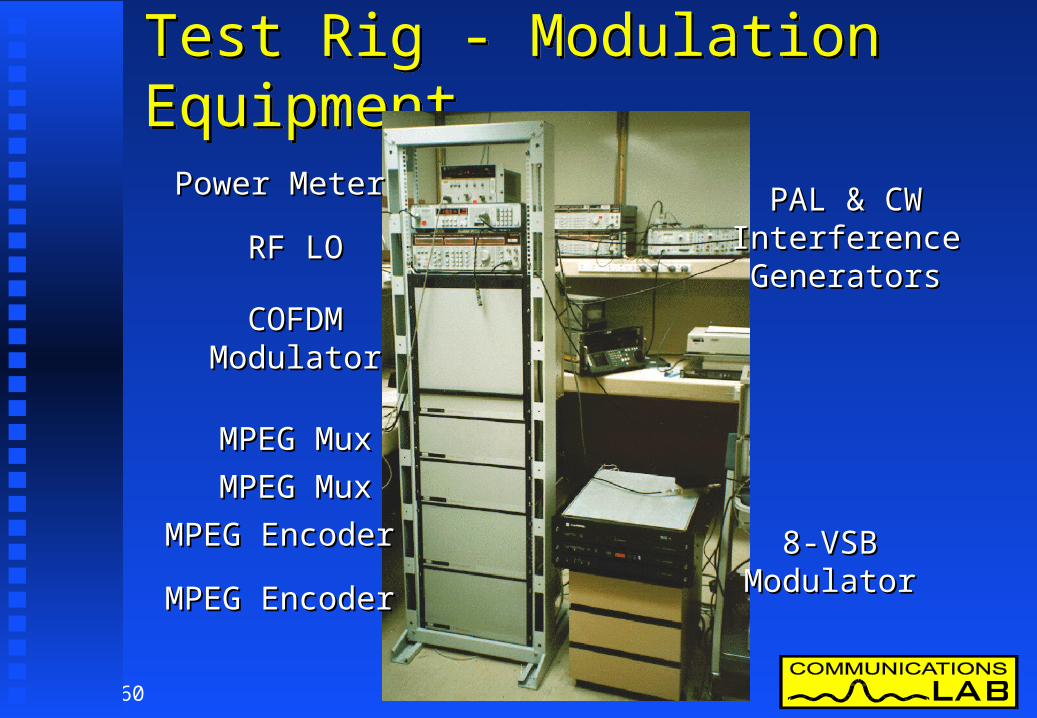
Test Rig - Modulation EquipmentTest Rig - Modulation Equipment
COFDMCOFDMModulatorModulator
MPEG MuxMPEG Mux
MPEG EncoderMPEG Encoder
MPEG EncoderMPEG Encoder
MPEG MuxMPEG Mux
8-VSB8-VSBModulatorModulator
RF LORF LO
Power MeterPower Meter PAL & CWPAL & CWInterferenceInterferenceGeneratorsGenerators

61
Laboratory Tests - TransmittersLaboratory Tests - Transmitters
Tx LOTx LOSpectrumSpectrumAnalyserAnalyser
Digital CRODigital CRO
HarrisHarrisExciterExciter
Power MeterPower MeterHarrisHarris1 kW 1 kW TxTx
NEC 200 W TxNEC 200 W Tx
LoadsLoads
Echo CombinerEcho Combiner

62
Digital Transmitters TCN-9 SydneyDigital Transmitters TCN-9 Sydney
Field Trial & DemonstrationField Trial & Demonstration
63
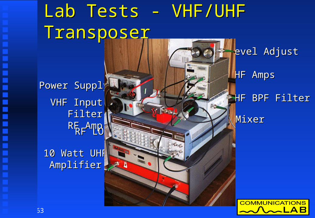
Lab Tests - VHF/UHF TransposerLab Tests - VHF/UHF Transposer
VHF Input FilterVHF Input FilterRF AmpRF Amp
MixerMixer
10 Watt UHF10 Watt UHFAmplifierAmplifier
RF LORF LO
Power SupplyPower Supply
Level AdjustLevel Adjust
UHF AmpsUHF Amps
UHF BPF FilterUHF BPF Filter

64
Order of MeasurementsOrder of Measurements
FACTS Advanced TV Specialists Group directed FACTS Advanced TV Specialists Group directed the priority of Testingthe priority of Testing
Laboratory Tests FirstLaboratory Tests First DTTB into PAL protectionDTTB into PAL protection DTTB System ParametersDTTB System Parameters PAL into DTTB protectionPAL into DTTB protection Other Interferers & DegradationsOther Interferers & Degradations
Field Tests LaterField Tests Later
65
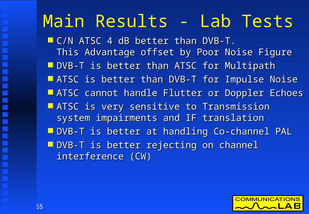
Main Results - Lab TestsMain Results - Lab Tests C/N ATSC 4 dB better than DVB-T.C/N ATSC 4 dB better than DVB-T.
This Advantage offset by Poor Noise FigureThis Advantage offset by Poor Noise Figure DVB-T is better than ATSC for MultipathDVB-T is better than ATSC for Multipath ATSC is better than DVB-T for Impulse NoiseATSC is better than DVB-T for Impulse Noise ATSC cannot handle Flutter or Doppler EchoesATSC cannot handle Flutter or Doppler Echoes ATSC is very sensitive to Transmission system ATSC is very sensitive to Transmission system
impairments and IF translationimpairments and IF translation DVB-T is better at handling Co-channel PALDVB-T is better at handling Co-channel PAL DVB-T is better rejecting on channel interference DVB-T is better rejecting on channel interference
(CW)(CW)
66
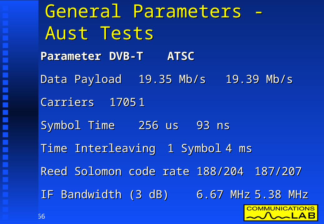
General Parameters - Aust TestsGeneral Parameters - Aust Tests
ParameterParameter DVB-TDVB-T ATSCATSC
Data PayloadData Payload 19.35 Mb/s19.35 Mb/s 19.39 Mb/s19.39 Mb/s
CarriersCarriers 17051705 11
Symbol TimeSymbol Time 256 us256 us 93 ns93 ns
Time InterleavingTime Interleaving 1 Symbol1 Symbol 4 ms4 ms
Reed Solomon code rateReed Solomon code rate 188/204188/204 187/207187/207
IF Bandwidth (3 dB)IF Bandwidth (3 dB) 6.67 MHz6.67 MHz 5.38 MHz5.38 MHz

67
Payload Bitrate Mb/s Pal C/I ProtectionCOFDM
MOD TYPE
FEC Code Rate
Sys C/N (dB)
Min Sig Level
(dBuV)
Calc Rx NF (dB)
Guard 1/4
(Mb/s)
Guard 1/8
(Mb/s)
Guard 1/16
(Mb/s)
Guard 1/32
(Mb/s)QPSK 1/2 5.4 11.7 4.8 4.35 4.84 5.12 5.28QPSK 2/3 6.6 13.2 5.1 5.81 6.45 6.83 7.04QPSK 3/4 7.6 14.8 5.7 6.53 7.26 7.68 7.92QPSK 5/6 8.7 16.8 6.6 7.26 8.06 8.54 8.80QPSK 7/8 9.5 19.2 8.2 7.62 8.47 8.96 9.24
16-QAM 1/2 11.2 17.7 5.0 8.71 9.68 10.25 10.5616-QAM 2/3 13.0 19.6 5.1 11.61 12.90 13.66 14.0716-QAM 3/4 14.1 20.9 5.3 13.06 14.51 15.37 15.8316-QAM 5/6 15.5 22.9 5.9 14.51 16.13 17.08 17.5916-QAM 7/8 16.3 24.9 7.1 15.24 16.93 17.93 18.4764-QAM 1/2 16.8 23.3 5.0 13.06 14.51 15.37 15.8364-QAM 2/3 19.1 25.2 4.6 17.42 19.35 20.49 21.1164-QAM 3/4 20.6 27.5 5.4 19.59 21.77 23.05 23.7564-QAM 5/6 22.2 30.0 6.3 21.77 24.19 25.61 26.3964-QAM 7/8 23.7 32.4 7.2 22.86 25.40 26.89 27.718-VSB 2/3 15.1 27.2 11.2 - - - 19.39
Blue Payload Figures are 188/204 scaled from actual measurementRed Figures are calculated from the 1/32 Guard interval data
C/N, NF & Payload Rate TableC/N, NF & Payload Rate Table
68
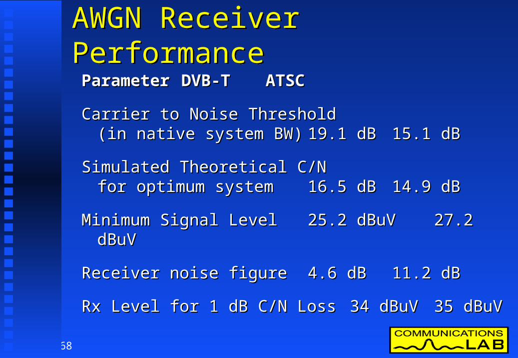
AWGN Receiver PerformanceAWGN Receiver Performance
ParameterParameter DVB-TDVB-T ATSCATSC
Carrier to Noise Threshold Carrier to Noise Threshold (in native system BW)(in native system BW) 19.1 dB19.1 dB 15.1 dB15.1 dB
Simulated Theoretical C/N Simulated Theoretical C/N for optimum systemfor optimum system 16.5 dB16.5 dB 14.9 dB14.9 dB
Minimum Signal LevelMinimum Signal Level 25.2 dBuV25.2 dBuV 27.2 dBuV27.2 dBuV
Receiver noise figureReceiver noise figure 4.6 dB4.6 dB 11.2 dB11.2 dB
Rx Level for 1 dB C/N LossRx Level for 1 dB C/N Loss 34 dBuV34 dBuV 35 dBuV35 dBuV

69
DTTB System Multipath CharacterDTTB System Multipath Character
00 33 1515 2525
15151919
3535
Multipath Level ( - dB)Multipath Level ( - dB)
8VSB8VSB
(64QAM, 2/3, 1/8)(64QAM, 2/3, 1/8)
C/N
Th
resh
old
(d
B)
C/N
Th
resh
old
(d
B)
Indoor Antenna Outdoor Antenna
(Conditions: Static multipath, Equal Rx NF, (Conditions: Static multipath, Equal Rx NF, No Co-channel or impulse interference)No Co-channel or impulse interference)
COFDMCOFDM

70
AWGN PerformanceAWGN Performance C/N 4 dB more power required for DVB-T to C/N 4 dB more power required for DVB-T to
achieve the same coverage as ATSC.achieve the same coverage as ATSC.
Better C/N performance ATSC offset by poor Better C/N performance ATSC offset by poor receiver noise figure receiver noise figure
ATSC C/N is very close to the theoretical DVB-T ATSC C/N is very close to the theoretical DVB-T implementation is still over 2.5 dB higher than implementation is still over 2.5 dB higher than the simulated margin.the simulated margin.
Other DVB-T modes have different C/N Other DVB-T modes have different C/N Thresholds and Data RatesThresholds and Data Rates

71
Multipath & Flutter MeasurementsMultipath & Flutter MeasurementsParameterParameter DVB-TDVB-T ATSCATSC
7.2 us Coax pre ghost7.2 us Coax pre ghost 0 dB0 dB -13.5 dB-13.5 dB
7.2 us Coax post ghost7.2 us Coax post ghost 0 dB0 dB -2.2 dB-2.2 dB
Echo correction rangeEcho correction range 32 us32 us +3 to -20 +3 to -20 usus
Doppler single echo performance Doppler single echo performance (-3 dB echoes)(-3 dB echoes) 140 Hz140 Hz 1 Hz1 Hz

72
Doppler Echo - 7.5 us Coax CableDoppler Echo - 7.5 us Coax CableDTTB 7.5 us Single Coax Doppler Echo
-25
-20
-15
-10
-5
0
-500 -400 -300 -200 -100 0 100 200 300 400 500
COFDM Post Echo
8-VSB Post Echo
Ech
o L
evel
E/D
(dB
)E
cho
Lev
el E
/D (
dB)
Frequency Offset (Hz)Frequency Offset (Hz)00-500-500 200200-200-200 500
-20-20
-10-10
-5-5
00
-15-15
-25-25
COFDMCOFDM8-VSB8-VSB

73
Transmitter Performance SensitivityTransmitter Performance Sensitivity
ParameterParameter DVB-TDVB-T ATSCATSC
Transmitter/Translator LinearityTransmitter/Translator Linearity & Inter-mod Sensitivity & Inter-mod Sensitivity LowLow HighHigh
Group Delay / Combiner / Group Delay / Combiner / Filter SensitivityFilter Sensitivity LowLow < 50 ns< 50 ns

74
Impulse Noise - ResultsImpulse Noise - Results
Impulse SensitivityImpulse Sensitivity (Differential to PAL grade 4) (Differential to PAL grade 4)
DVB-TDVB-T 9 -14 dB 9 -14 dB ATSC ATSC 17-25 dB17-25 dB
Difficult to measure & characterise.Difficult to measure & characterise.
Mainly affects the lower VHF frequenciesMainly affects the lower VHF frequencies
ATSC is 8 to 11 dB better at handling ATSC is 8 to 11 dB better at handling impulsive noise than DVB-Timpulsive noise than DVB-T

75
Impulse Noise - PlotImpulse Noise - Plot

76
DTTB into PAL - SubjectiveDTTB into PAL - SubjectiveD T T B in to P A L B P ro t e c t io n D /U (d B )
S y s t e m T e s t D e s c rip t io n M e a n S td D e v N u m M in M e d ia n M a xD VB -T 7 M H z C h 7 lo w e r a d j. c h . -9.5 3.3 12 -14.0 -10.0 -4.0T ro p o s p h e ric C h 8 C o -C h a n n e l 35.8 1.4 12 33.5 36.0 38.5In t e rfe re n c e C h 9 u p p e r a d j. c h . -10.6 4.9 12 -20.0 -10.0 -3.0
D VB -T 7 M H z C h 7 lo w e r a d j. c h . -5.3 3.8 12 -9.5 -6.5 2.5C o n t in u o u s C h 8 C o -C h a n n e l 41.1 2.0 12 38.5 40.8 45.0In t e rfe re n c e C h 9 u p p e r a d j. c h . -6.4 4.3 12 -14.0 -6.8 1.0
D VB -T 7 M H z C h 7 lo w e r a d j. c h . 3.5 3.8 12 -2.5 2.8 10.0Limit o f C h 8 C o -C h a n n e l 50.4 0.9 14 48.5 50.3 52.0
P e rc e p t ib ilit y C h 9 u p p e r a d j. c h . 5.1 5.8 16 -1.0 3.8 20.0A T S C 6 M H z C h 7 lo w e r a d j. c h . -7.0 3.4 15 -12.5 -7.0 -2.0T ro p o s p h e ric C h 8 C o -C h a n n e l 38.7 2.6 41 34.5 38.5 44.0In t e rfe re n c e C h 9 u p p e r a d j. c h . -7.1 3.5 17 -14.0 -6.0 -3.5
A T S C 6 M H z C h 7 lo w e r a d j. c h . -0.9 4.3 15 -5.5 -2.0 8.0C o n t in u o u s C h 8 C o -C h a n n e l 45.5 2.2 41 41.0 45.0 50.5In t e rfe re n c e C h 9 u p p e r a d j. c h . -0.3 2.9 17 -5.5 0.0 3.0
A T S C 6 M H z C h 7 lo w e r a d j. c h . 5.0 4.4 15 0.0 4.0 13.0Limit o f C h 8 C o -C h a n n e l 51.4 2.5 41 47.0 51.5 56.5
P e rc e p t ib ilit y C h 9 u p p e r a d j. c h . 5.4 3.1 17 0.0 4.5 10.5

77
PAL into DTTB - Protection PlotPAL into DTTB - Protection PlotPal into DTTB Protection Ratio Comparison for 50 dBuV DTTB Signals
-45
-40
-35
-30
-25
-20
-15
-10
-5
0
5
10
-8 -7 -6 -5 -4 -3 -2 -1 0 1 2 3 4 5 6 7 8
8-VSB
COFDM
00-1-1-2-2-3-3-4-4-5-5-6-6-7-7-8-8 11 22 33 44 55 66 77 88Frequency Offset (MHz)Frequency Offset (MHz)
00
-10-10
-20-20
-30-30
-40-40
Pro
tect
ion
Rat
io D
/U (
dB)
Pro
tect
ion
Rat
io D
/U (
dB)
1010

78
Off Air PAL into DTTB - PlotOff Air PAL into DTTB - PlotPal into DTTB Protection with real Off Air Pal signals either side of DTTB Channel 8
Note: Channel 7 only has a single monophonic Sound
carrier which is 10 dB below the Vision carrier level
-40
-35
-30
-25
-20
-15
-10
-5
0
5
-2000 -1500 -1000 -500 0 500 1000 1500 2000
7 MHz COFDM
6 MHz 8VSB
00
-10-10
-20-20
-30-30
-40-40
-35-35
Pro
tect
ion
Rat
io D
/U (
dB)
Pro
tect
ion
Rat
io D
/U (
dB)
55
-5-5
-15-15
-25-25
00-0.5-0.5-1-1-1.5-1.5-2-2 11 220.50.5
Channel 8 DTTB Frequency Offset (MHz)Channel 8 DTTB Frequency Offset (MHz)
1.51.5

79
CW into DTTB - Protection PlotCW into DTTB - Protection PlotCW Interferer into DTTB Protection Ratio Comparison for 50 dBuV DTTB Signals
-50
-45
-40
-35
-30
-25
-20
-15
-10
-5
0
5
10
15
-8 -7 -6 -5 -4 -3 -2 -1 0 1 2 3 4 5 6 7 8
8-VSB
COFDM
00-1-1-2-2-3-3-4-4-5-5-6-6-7-7-8-8 11 22 33 44 55 66 77 88Frequency Offset (MHz)Frequency Offset (MHz)
00
-10-10
-20-20
-30-30
-40-40
-50-50
Pro
tect
ion
Rat
io D
/U (
dB)
Pro
tect
ion
Rat
io D
/U (
dB)
1010

80
DTTB into DTTB - OverviewDTTB into DTTB - Overview
D T T BT Y P E
C h 7 L o w e rA d j C h (d B )
C o C h a n n e l(d B )
C h 9 U p p e rA d j C h (d B )
D V B -T -7 -2 8 .3 2 0 -2 8 .5A T SC -6 -3 0 .4 1 4 .6 -3 2 .2
Adjacent channel performance of ATSC is better Adjacent channel performance of ATSC is better than DVB-Tthan DVB-T
The Co-channel protection of both digital systems The Co-channel protection of both digital systems approximates to the system carrier to noise approximates to the system carrier to noise threshold.threshold.

81
DTTB into DTTB - Protection PlotDTTB into DTTB - Protection PlotDTTB into DTTB Protection
-35
-30
-25
-20
-15
-10
-5
0
5
10
15
20
25
-8 -7 -6 -5 -4 -3 -2 -1 0 1 2 3 4 5 6 7 8
COFDM
8-VSB
00-1-1-2-2-3-3-4-4-5-5-6-6-7-7-8-8 11 22 33 44 55 66 77 88Frequency Offset of Unwanted DTTB (MHz)Frequency Offset of Unwanted DTTB (MHz)
00
-10-10
-20-20
-30-30
2020
Pro
tect
ion
Rat
io D
/U (
dB)
Pro
tect
ion
Rat
io D
/U (
dB)
1010

82
Field TestingField Testing A field test vehicle was built in a small van.A field test vehicle was built in a small van.
83
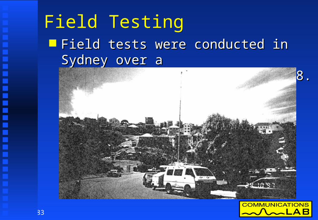
Field TestingField Testing Field tests were conducted in Sydney over a Field tests were conducted in Sydney over a
1 month period on VHF channel 8.1 month period on VHF channel 8.

84
Field TestingField Testing
Over 115 sites were measuredOver 115 sites were measured Power level for the field test was 14 dB below Power level for the field test was 14 dB below
adjacent analog television channels 7 & 9adjacent analog television channels 7 & 9 Analog and digital television performance for Analog and digital television performance for
both systems were evaluated at each site.both systems were evaluated at each site.
85
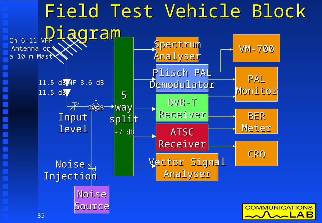
Field Test Vehicle Block DiagramField Test Vehicle Block DiagramField Test Vehicle Block DiagramField Test Vehicle Block Diagram
NoiseNoiseSourceSource
55waywaysplitsplit
SpectrumSpectrumAnalyserAnalyser
Plisch PALPlisch PALDemodulatorDemodulator
DVB-TDVB-TReceiverReceiver
ATSCATSCReceiverReceiver
Vector SignalVector SignalAnalyserAnalyser
BERBERMeterMeter
CROCRO
PALPALMonitorMonitor
VM-700VM-700
-20dB-20dB
11.5 dB11.5 dB
11.5 dB11.5 dB
NF 3.6 dBNF 3.6 dB
-7 dB-7 dB
InputInputlevellevel
NoiseNoiseInjectionInjection
Ch 6-11 VHFCh 6-11 VHFAntenna onAntenna ona 10 m Masta 10 m Mast

86
Field Testing - MethodField Testing - Method Field tests were conducted in Sydney over a Field tests were conducted in Sydney over a
1 month period on VHF channel 8. 1 month period on VHF channel 8. Some simultaneous tests were conducted on VHF Some simultaneous tests were conducted on VHF
channel 6channel 6 Power level for the field test was 14 dB below Power level for the field test was 14 dB below
adjacent analog television channels 7 & 9 adjacent analog television channels 7 & 9 Analog and digital television performance for both Analog and digital television performance for both
systems were evaluated at each site.systems were evaluated at each site. Conducted by Independent Consultant & Mr Wayne Conducted by Independent Consultant & Mr Wayne
Dickson of TENDickson of TEN

87
Field Test - Data Collected each SiteField Test - Data Collected each Site
Common Masthead Amp used (NF ~ 3.6 dB)Common Masthead Amp used (NF ~ 3.6 dB) Analog PAL transmission character (7,9 & 10)Analog PAL transmission character (7,9 & 10) Measure level, multipath, quality & Video S/NMeasure level, multipath, quality & Video S/N Measure DVB & ATSC reception (Ch 8)Measure DVB & ATSC reception (Ch 8) Record DTTB & Analog SpectrumRecord DTTB & Analog Spectrum Measure Noise Margin (C/N Margin)Measure Noise Margin (C/N Margin) Measure Level Threshold (Signal Margin)Measure Level Threshold (Signal Margin) Measure antenna off pointing sensitivityMeasure antenna off pointing sensitivity

88
0
5
10
15
20
25
30
35
40
Sit
e R
EC
EIV
E M
AR
GIN
(d
B)
45 50 55 60 65 70 75 80 85 90 95 100 105 110
Site Field Strenght (dBuV/m)
PAL - SITE RECEIVE MARGINFacts DTTB Trial Sites
PAL on CH9
Plisch Receiver
W.T.D. 5 JUNE 1998
Nominal conditions : 7 dB gain Antenna + 2 dB leed loss @ CH9
MINIMUM ACCEPTABLE PICTURE
Minimum F/S = 55dBuV/m
Margin to minimum acceptablepicture w/o multipath
for HIGH GAIN ANTENNA
Receiver limitations
Effective decoder Noise Figure (NF) = 5 dB
Australian DTTB Field Trial PAL Receive Margin
Australian DTTB Field Trial PAL Receive Margin

89
Australian DTTB Field Trial DTTB compared to PAL
Australian DTTB Field Trial DTTB compared to PAL
-45
-40
-35
-30
-25
-20
-15
Vid
eo S
/N
of PA
L @
D
TTB
TH
RE
SH
OLD
(d
B)
0 5 10 15 20 25 30 35 40 45 50 55 60 65 70 75 80 85 90 95 100 105 110 115
TEST #
PAL VIDEO S/N @ DTTB THRESHOLD@ 14dB nominal DTTB to PAL ratio
System Noise Method
8VSB
COFDM (64QAM,2/3,1/8)
Note : 8VSB Launch power on average was 0.8dB higher than COFDM Launch power
Average S/N @ Threshold of :8VSB = -24.2dB unwtd (PAL)COFDM = -28.7dB unwtd (PAL)
FACTS DTTB Trial Sites
W.T.D. 15 Jan 1998

90
Australian DTTB Field Trial 8VSB Decoder Margin
Australian DTTB Field Trial 8VSB Decoder Margin
0
10
20
30
40
50
60
Sit
e D
EC
OD
E M
AR
GIN
(dB
)
25 30 35 40 45 50 55 60 65 70 75 80 85 90
Site Field Strenght (dBuV/m)
8VSB SITE DECODE MARGINFACTS DTTB Trial Sites
8VSB
System Noise MethodW.T.D. 7 JUNE 1998
Nominal conditions : 7 dB gain Antenna + 2 dB leed lossEffective decoder Noise Figure (NF) = 9 dB
NO PICTURE
Minimum F/S = 37 dBuV/m
without multipath
and 3 dB margin
Margin @ Threshold C/N
w/o multipath
Decoder NF = 9 dB
for a HIGH GAIN ANTENNA
Minimum F/S = 47 dBuV/m
with multipath allowance
and 3 dB marginMargin @ threshold C/N
with multipath

91
Australian DTTB Field Trial COFDM Decoder Margin
Australian DTTB Field Trial COFDM Decoder Margin
0
10
20
30
40
50
60 Sit
e D
EC
OD
E M
AR
GIN
(dB
)
25 30 35 40 45 50 55 60 65 70 75 80 85 90
Site Field Strenght (dBuV/m)
COFDM SITE DECODE MARGINFACTS DTTB Trial Sites
COFDM (64QAM,2/3,1/8)
System Noise Method
W.T.D. 5 JUNE 1998
Nominal conditions : 7 dB gain Antenna + 2 dB leed loss @ CH8
Effective decoder Noise Figure (NF) = 5 dB
NO PICTURE
Minimum F/S = 37 dBuV/m
without mutipath
and 3 dB margin
Margin @Threshold C/N
w/o multipath
Decoder NF = 5 dB
for a HIGH GAIN ANTENNA
Minimum F/S = 45 dBuV/m
with multipath allowance
and 3 dB marginMargin @ Threshold C/N
with Multipath
92
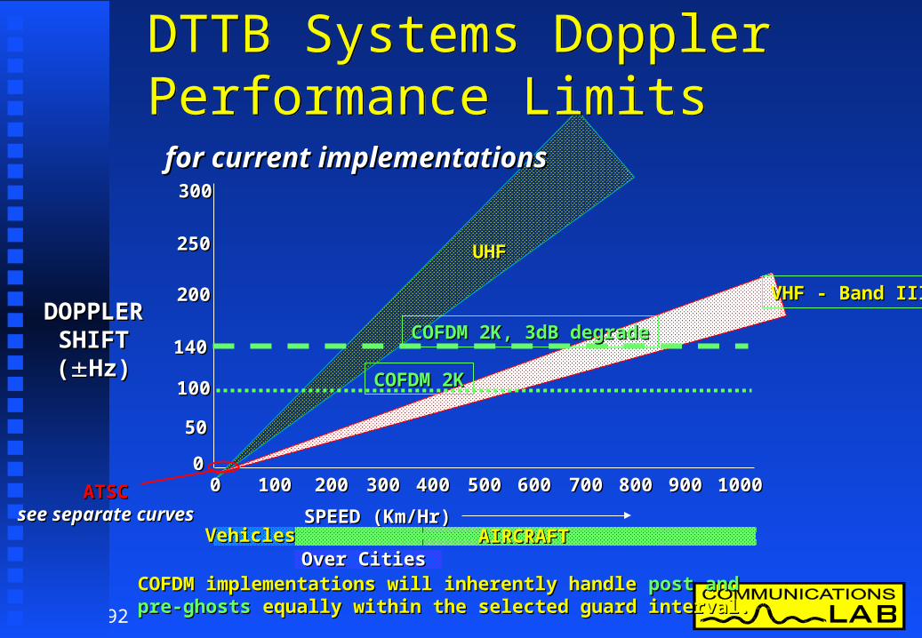
VHF - Band IIIVHF - Band III
UHFUHF
DOPPLERDOPPLERSHIFTSHIFT((Hz)Hz)
140 140
300300
0000 10001000500500100100 200200 300300 400400 600600 700700 800800 900900
100100
5050
200200
250250
COFDM 2K, 3dB degradeCOFDM 2K, 3dB degrade
COFDM 2KCOFDM 2K
SPEED (Km/Hr)SPEED (Km/Hr)AIRCRAFTAIRCRAFTVehiclesVehicles
Over CitiesOver Cities
for current implementationsfor current implementations
ATSCATSCseesee separateseparate curvescurves
COFDM implementations will inherently handleCOFDM implementations will inherently handle post andpost and pre-ghostspre-ghosts equally within the selected guard interval.equally within the selected guard interval.
DTTB Systems Doppler Performance LimitsDTTB Systems Doppler Performance Limits

93
VHF - Band IIIVHF - Band III
UHFUHF
0000 100100
8VSB, “Fast Mode”, 3dB degrade8VSB, “Fast Mode”, 3dB degrade
SPEED (Km/Hr)SPEED (Km/Hr)
VehiclesVehicles
8VSB8VSB
55
1
1010
3030232310106622
AircraftAircraft
8VSB implementations of equalisers are likely to cater for8VSB implementations of equalisers are likely to cater for post ghostspost ghosts up toup to 30 uSec30 uSec andand pre-ghostspre-ghosts up toup to 3 uSec 3 uSec onlyonly..
DOPPLERDOPPLERSHIFTSHIFT((Hz)Hz)
ATSC 8-VSB Doppler Performance LimitsATSC 8-VSB Doppler Performance Limits

94
Field Test - ObservationsField Test - Observations
At -14 dB DTTB power when there was a At -14 dB DTTB power when there was a reasonable PAL picture both 8-VSB & COFDM reasonable PAL picture both 8-VSB & COFDM worked at the vast majority of Sitesworked at the vast majority of Sites
When PAL had:When PAL had: Grain (noise) and some echoes (multipath), Grain (noise) and some echoes (multipath),
both 8-VSB & COFDM failedboth 8-VSB & COFDM failed Flutter, caused by aircraft or vehicles, 8-VSB failedFlutter, caused by aircraft or vehicles, 8-VSB failed Impulsive noise & some grain, COFDM failedImpulsive noise & some grain, COFDM failed
95
The Tests - Some World FirstsThe Tests - Some World Firsts
First independent direct comparative tests First independent direct comparative tests between the two digital modulation systemsbetween the two digital modulation systems
First extensive tests of both systems in aFirst extensive tests of both systems in a7 MHz PAL-B channel environment7 MHz PAL-B channel environment
First tests of VHF adjacent channel operationFirst tests of VHF adjacent channel operation First test of ATSC in a PAL environmentFirst test of ATSC in a PAL environment First test of DVB-T in the VHF bandFirst test of DVB-T in the VHF band

96
HDTV - DemonstrationsHDTV - Demonstrations
In October and November 1997 the ATSC and In October and November 1997 the ATSC and DVB-T system proponents both demonstrated DVB-T system proponents both demonstrated their systems by transmitting HDTV programs to their systems by transmitting HDTV programs to audiences in Sydney.audiences in Sydney.
These demonstrations showed that These demonstrations showed that both systems were HDTV capable.both systems were HDTV capable.

97
Test ReportsTest Reports
Lab and field data was compiled and factually Lab and field data was compiled and factually presented in detailed reports.presented in detailed reports.
Aim to present data in an unbiased way without Aim to present data in an unbiased way without drawing conclusions based on single parametersdrawing conclusions based on single parameters
Summary reports for both the laboratory and field Summary reports for both the laboratory and field trials were also produced, concentrating on the trials were also produced, concentrating on the interesting data.interesting data.
These reports provided a solid technical basis to These reports provided a solid technical basis to assess the two DTTB modulation systems.assess the two DTTB modulation systems.

98
The Selection CommitteeThe Selection Committee
A selection committee was formed A selection committee was formed from FACTS ATV specialists group from FACTS ATV specialists group Representing:Representing: National broadcasters (ABC and SBS)National broadcasters (ABC and SBS) The commercial networks (7,9 & 10)The commercial networks (7,9 & 10) The regional commercial broadcastersThe regional commercial broadcasters The Department of Communications The Department of Communications
and the Artsand the Arts The Australian Broadcasting AuthorityThe Australian Broadcasting Authority

99
Selection Panel - ResponsibilitySelection Panel - Responsibility
Analysing the comparative tests and other Analysing the comparative tests and other available factual informationavailable factual information
Establishing the relevance of the Establishing the relevance of the performance differences to Australian performance differences to Australian broadcastingbroadcasting
Recommending the system to be usedRecommending the system to be used
100
Selection Result - June 1998Selection Result - June 1998
The selection committee The selection committee unanimously selected the unanimously selected the 7 MHz DVB-T modulation system 7 MHz DVB-T modulation system for use in Australiafor use in Australia
The criteria that were set aside would, The criteria that were set aside would, however, not have changed the selection however, not have changed the selection decisiondecision
101
More SelectionsMore Selections
Sub-committees formed to investigate:Sub-committees formed to investigate: Service information data standardService information data standard Multichannel audio systemMultichannel audio system HDTV video production format HDTV video production format
July 1998 3 further recommendationsJuly 1998 3 further recommendations SI data standard be based on DVB-SISI data standard be based on DVB-SI AC3 multichannel audio is the AC3 multichannel audio is the
preferred audio encoding formatpreferred audio encoding format 1920/1080/50 Hz interlaced 1125 lines is the 1920/1080/50 Hz interlaced 1125 lines is the
preferred video production formatpreferred video production format

102
Multichannel Sound - MPEG 1/2Multichannel Sound - MPEG 1/2 Two sound coding systems existTwo sound coding systems exist MPEG Audio Layer II was developed in MPEG Audio Layer II was developed in
conjunction with the European DVB technologyconjunction with the European DVB technology Uses Musicam Compression with 32 sub bandsUses Musicam Compression with 32 sub bands MPEG 1 is basic Stereo 2 channel modeMPEG 1 is basic Stereo 2 channel mode MPEG 2 adds enhancement information to allow 5.1 MPEG 2 adds enhancement information to allow 5.1
or 7.1 channels with full backwards compatibility or 7.1 channels with full backwards compatibility with the simple MPEG 1 decoderswith the simple MPEG 1 decoders
MPEG 1 Is compatible with Pro-Logic processing.MPEG 1 Is compatible with Pro-Logic processing. Bitrate 224 kb/s MPEG 1Bitrate 224 kb/s MPEG 1 Bitrate 480 kb/s MPEG 2 5.1Bitrate 480 kb/s MPEG 2 5.1

103
Multichannel Sound - Dolby AC-3Multichannel Sound - Dolby AC-3 Dolby AC-3 was developed as a 5.1 channel Dolby AC-3 was developed as a 5.1 channel
surround sound system from the beginning. surround sound system from the beginning. Compression Filter bank is 8 x greaterCompression Filter bank is 8 x greater
than MPEG 2 (256) than MPEG 2 (256) Must always send full 5.1 channel mix Must always send full 5.1 channel mix
One bitstream serves everyoneOne bitstream serves everyone Decoder provides downmix for Decoder provides downmix for
Mono, Stereo or Pro-LogicMono, Stereo or Pro-Logic Listener controls the dynamic range, Listener controls the dynamic range,
Audio is sent cleanAudio is sent clean Bitrate 384 kb/s or 448 kb/s Bitrate 384 kb/s or 448 kb/s

104
Studio Multichannel Sound Studio Multichannel Sound Present AES3 PCM Audio Present AES3 PCM Audio
does not cater for 5.1 channel surround.does not cater for 5.1 channel surround. Dolby has produced a system called Dolby EDolby has produced a system called Dolby E
Handles 6-8 audio inputsHandles 6-8 audio inputs Uses low compression 3-4:1Uses low compression 3-4:1 Can be transported/stored on 2ch PCM audio Can be transported/stored on 2ch PCM audio
equipmentequipment Incorporates time stamps and is segmented at the Incorporates time stamps and is segmented at the
video frame rate allowing editing on video frame video frame rate allowing editing on video frame boundariesboundaries

105
Display TechnologyDisplay Technology For HDTV displays need to be largeFor HDTV displays need to be large Captures viewers perceptual visionCaptures viewers perceptual vision Viewing distance will be closer (3H)Viewing distance will be closer (3H) Largest CRT Tubes limited by sizeLargest CRT Tubes limited by size Projectors are expensive and BulkyProjectors are expensive and Bulky Flat Panel Display Technology seen as theFlat Panel Display Technology seen as the
HDTV display technology of the futureHDTV display technology of the future Producing large flat panels is difficultProducing large flat panels is difficult

106
Plasma Panel DisplaysPlasma Panel Displays PDPs from Fujitsu & Mitsubishi look like PDPs from Fujitsu & Mitsubishi look like
providing HDTV Display solution.providing HDTV Display solution. Latest innovations such as ALiS have doubled Latest innovations such as ALiS have doubled
the vertical resolution to over 1000 lines.the vertical resolution to over 1000 lines.

107
Staging & SetsStaging & Sets HDTV resolution & Aspect ratio will mean HDTV resolution & Aspect ratio will mean
changes to production:changes to production: Greater attention to detailGreater attention to detail Set construction Set construction Set painting more accurateSet painting more accurate Makeup Makeup Lighting (more light)Lighting (more light) Framing of Shots (4:3, 14:9, 16:9, 2.21:1)Framing of Shots (4:3, 14:9, 16:9, 2.21:1) Use of Zoom & PanUse of Zoom & Pan

108
Studio/Field StorageStudio/Field Storage
Digital Video Tape probably 270 Mb/s.Digital Video Tape probably 270 Mb/s. D5 & D1 have been used up to now.D5 & D1 have been used up to now.
3-4 times compression applied to the HDTV material 3-4 times compression applied to the HDTV material for storage => Need HD encoder between camera & for storage => Need HD encoder between camera & Storage deviceStorage device
Disk Video ServersDisk Video Servers Compressed transport stream storage Compressed transport stream storage
(20-50 Mb/s) on SX, D-Bcam, DVC-PRO etc.(20-50 Mb/s) on SX, D-Bcam, DVC-PRO etc. New formats will be developed, not here yet.New formats will be developed, not here yet.

109
Government LegislationGovernment Legislation
While the selection process was underway the While the selection process was underway the Australian government considered legislation to Australian government considered legislation to define the implementation of digital television define the implementation of digital television services in Australia. services in Australia. Two Acts have been passed.Two Acts have been passed. Television broadcasting services Television broadcasting services
(digital conversion) Act 1998(digital conversion) Act 1998 Datacasting charge (imposition) Act 1998Datacasting charge (imposition) Act 1998
110
The Digital Conversion Act - 1The Digital Conversion Act - 1
Mandates HDTV content level requirementMandates HDTV content level requirement 5 FTA broadcasters get a free loan of adjacent 5 FTA broadcasters get a free loan of adjacent
channel spectrum to start DTVchannel spectrum to start DTV Simulcasting of digital and analog services is Simulcasting of digital and analog services is
required for at least 8 years after digital startuprequired for at least 8 years after digital startup Jan 1 2001 commencement in metro marketsJan 1 2001 commencement in metro markets Commencement by 2004 in regional marketsCommencement by 2004 in regional markets Multi-channel and subscription services not Multi-channel and subscription services not
allowed for commercial broadcasters allowed for commercial broadcasters

111
The Digital Conversion Act - 2The Digital Conversion Act - 2
Multi-view programs may be allowed subject to Multi-view programs may be allowed subject to reviewreview
Review before 2000 if National broadcasters Review before 2000 if National broadcasters should be allowed some multi-channelling to should be allowed some multi-channelling to address community needsaddress community needs
No new commercial broadcasting services No new commercial broadcasting services until 2007until 2007
Closed captioning is required on some servicesClosed captioning is required on some services Minister can determine digital system standardMinister can determine digital system standard

112
The Datacasting Imposition Act - 1The Datacasting Imposition Act - 1 Datacasting defined as services Datacasting defined as services
“other than a broadcasting service” “other than a broadcasting service” delivered using broadcasting spectrumdelivered using broadcasting spectrum
Unused spectrum after planning of digital TV Unused spectrum after planning of digital TV services - available to datacasters - via auctionservices - available to datacasters - via auction
FTA broadcasters unable to bid for datacasting FTA broadcasters unable to bid for datacasting spectrum allocationsspectrum allocations
Community television access is to be provided Community television access is to be provided by datacaster free of charge by datacaster free of charge

113
The Datacasting Imposition Act - 2The Datacasting Imposition Act - 2 Review before 2000 to determine the types of Review before 2000 to determine the types of
services to be allowed as datacastingservices to be allowed as datacasting Datacasters not allowed to provide de-facto Datacasters not allowed to provide de-facto
broadcast or Pay TV type services broadcast or Pay TV type services FTA Broadcasters may use spare transmission FTA Broadcasters may use spare transmission
capacity for datacastingcapacity for datacasting FTA broadcasters will be charged if they FTA broadcasters will be charged if they
provide datacast servicesprovide datacast services

114
What Are the Next Steps?What Are the Next Steps?
Standards Australia - CT/2 committeesStandards Australia - CT/2 committees In Process at presentIn Process at present Develop transmission standardsDevelop transmission standards Develop reception equipment standardsDevelop reception equipment standards Draft standards ready by early 1999Draft standards ready by early 1999

115
On Air TestingOn Air Testing
NTA VHF & UHF trialsNTA VHF & UHF trials 2K & 8K operation 2K & 8K operation Planning Planning SFNs SFNs Gap fillersGap fillers
Ch 12 VHFCh 12 VHF@ 2.5 kW@ 2.5 kW
CH 29 UHFCH 29 UHF@ 1.25 kW@ 1.25 kW
116
Channel 9AChannel 9A
SBS want to use band III 6 MHz SBS want to use band III 6 MHz channel 9A in metro areaschannel 9A in metro areasoptions:options: Truncation of 7 MHz COFDMTruncation of 7 MHz COFDM Transmission of 6 MHz COFDMTransmission of 6 MHz COFDM Offsetting digital/analog transmissionsOffsetting digital/analog transmissions

117
Propagation InvestigationsPropagation Investigations
Indoor reception testsIndoor reception tests Multipath propagationMultipath propagation Building attenuationBuilding attenuation Impulse sensitivityImpulse sensitivity
Adjacent area co-channel simulcast operationAdjacent area co-channel simulcast operation
118
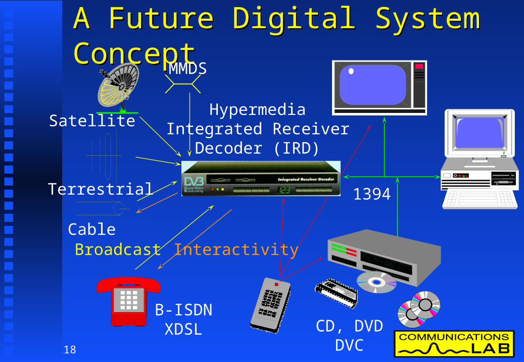
A Future Digital System ConceptA Future Digital System Concept
HypermediaIntegrated Receiver
Decoder (IRD)
MMDS
Satellite
Terrestrial
Cable
B-ISDNXDSL CD, DVD
DVC
Broadcast Interactivity
1394

119
The EndThe End
Thankyou for your attentionThankyou for your attention
Any questions?Any questions?