1 darrin marr marcie webb brad zarikoff digital input power meter
Post on 18-Dec-2015
216 views
TRANSCRIPT

1
Darrin Marr
Marcie Webb
Brad Zarikoff
Digital Input Power Meter

2
Introduction
• Background
• Design and operation
• Progress and problems encountered

3
Project Goals
• To design a Power Meter that accepts a digital input
• Reduce the redundancy in conventional technology
• Improve on Power Measurement for Utility Industry

4
Application Overview
• Power Meters are typically used in substations
• Current and voltage transducers feed power meters
• You cannot connect an oscilloscope to 138 000 volts

5
Conventional Technology
IPP tap from utility breakers
Analogue Meter
(Analogue Metering)
120V analogue signal
Current Sensor
Voltage Sensor
NXVCT
IPP owned equipment 138 kV
13.8 kV
Stn. Service Xfmr.475 kW load
Utility owned equipment
Gas Turbine Generators225 MVA13.8 kV, 60 Hz
Optical Current Electronics
DAC, Amplifier
Optical Voltage Electronics
DAC, Amplifier
- 0.2% accuracy over 2 – 3000A range
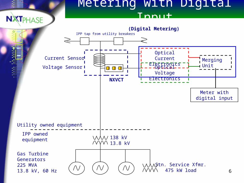
6
Metering with Digital Input
Meter with digital input
(Digital Metering)
Current Sensor
Voltage Sensor
NXVCT
Optical Current Electronics
Optical Voltage Electronics
IPP owned equipment 138 kV
13.8 kV
Stn. Service Xfmr.475 kW load
Utility owned equipment
Gas Turbine Generators225 MVA13.8 kV, 60 Hz
IPP tap from utility breakers
Merging Unit

7
Meters
P
Us
er D
isp
lay
Digital Input Meter
101101010001
ADC P
An
alo
g S
ign
al
Co
nd
ition
ing
Us
er D
isp
lay
ConventionalAnalog Input Meter

8
Corporate Sponsorship
• NxtPhase is a company that makes Voltage and Current Transducers
• NxtPhase uses optics to measure the line voltage or current
• Optical signal is transduced to voltage and digitized
• Dedicated to “Digitizing the Grid”

9
Keeping NxtPhase Happy
• NxtPhase does not make Power Meters
• Want to interface to next generation Digital Input Power Meters and Protection Relays
• Need to develop a Merging Unit to IEC 60044-8 standard

10
• Current and voltage emulation
• Current and voltage data merging unit
• Receiving and data decoding unit
• Data display
Digital Input Power Meter

11
Digital Input Power Meter Layout
Sinew aveGenerator
Merging Unit"Merges
Channels"
Buffer Board"Deserialize"
P C
6 Channelson one TDM
serial bus
ProprietaryBit and
Sam ple Rate2.5 Mbps4.8 kHz fs
continuous
16 bitparallel
"Batch Type"System
5760 Sam ples/0.2 s

12
Sine Wave Generator
• Used to generate three-phase voltage and current received from NxtPhase equipment
• Simulates three voltage and current signals
• Output at NxtPhase proprietary data and sampling rate as TDM signal

13
Merging Unit
• Takes TDM data of six sinusoids and packetizes them into data stream for transmission
• Outputs packets at 2.5Mbps at 4.8kHz sampling rate
• Continuous packet output (no idle)• Averages samples (NxtPhase sampling
rate much faster than IEC standard)

14
Packet Standard
• Packetized in accordance with IEC 60044-8 standard
• Packet standard incorporates three-phase metering, protection, and unit data, error control (CRC)

15
Merging Unit
SC of ECTa (meas.)
Merging unit
SC of ECTb (meas.)
SC of ECTc (meas.)
SC of EVTa
SC of EVTb
SC of EVTc
Digitaloutput
SC of EVT neutral
SC of EVT busbar
SC of ECTa (prot.)
SC of ECTb (prot.)
SC of ECTc (prot.)
SC of ECT neutral
Merging unitpower supply

16
Buffer Board
• Transmission along data line to allow for remote monitoring
• Buffer board decodes data packet and buffers data (0.2s worth) for burst transmission
• National Instrument DAQ card dumps data into file on PC to be used by meter display

17
Data Display
• Visual Basic in Excel application• Retrieves voltage and current data from
data file every x seconds• Formats and displays current and
voltage information• Calculates voltage and current spectrum,
power factor, and RMS values

18
Debug Board
DSP to Buffer Data StreamPCIData Aquisition Card
Via DeviceDriver or 3rd
PartySoftware
Data File(Specified
Maximum Size)
Visual Basic GUI
Dig ital Interface M eter
PC
Read OnlyData "Snapshots"
Via DB25Connection
NRZ, 2.5 Mbps,4.8kHz Sample(Frame) Rate
"Merged Data"
2.5 MHz Serial Clock
Em m ulation of a Digital Interface M eter
Digital Interface Meter

19
Project Status
• Verification stage at present
• All design and implementation complete
• Currently testing to ensure reliable operation
• Visit our demo on Friday in ELW
20
Problems Encountered
• No copy of Matlab for meter display development– Would have been excellent tool for data
display and manipulation
• Now using Visual Basic in Excel – Limited mathematical capabilities– Slow graphing capabilities

21
Problems Encountered
• Original design included fiber optic link between Merging Unit and Digital Meter
• Researched options available– Found inexpensive development kit
• Lack of time forced us to abandon testing and implementation
• Fiber optics used to avoid EMI

22
ManchesterEncoderPreliminary Merging Unit
ManchesterEncoded Data
OpticalTransceiver
O ptica lF ibre
ManchesterEncoded DataManchester
Decoder
NRZ, 2.5 Mbps,4.8kHz Sample(Frame) Rate
"Merged Data"
2.5 MHz Serial Clock
NRZ, 2.5 Mbps,4.8kHz Sample(Frame) Rate
"Merged Data"
2.5 MHz Serial Clock
Digital Interface MeterOptical
Transceiver
Transm ission Strategy

23
Error Detection
• IEC 60044-8 standard includes CRC error detection code– Uses three 16-bit CRC checks
• Possible to have better error detection with less CRC bits required– One 32-bit CRC check would have
better detection capabilities

24
Conclusions
• Digital input power meter currently not available commercially– NxtPhase has interest because need to
connect PT’s to digital meters
• Realizable with more time
• NxtPhase will be able to use Merging Unit design as step towards useable product

25
Questions?