1 descriptions of function - eprismartgrid.epri.com/usecases/nedo l3 usecase bems v6.pdfnedo local...
TRANSCRIPT

NEDO Local Level Use Case #L3
L3_UseCase(BEMS)v6.doc 1 6/17/2011
BBEEMMSS ccoonnttrrooll ooff DDEERRss aanndd HHVVAACC eeqquuiippmmeenntt iinn aa ccoommmmeerrcciiaall bbuuiillddiinngg wwhhiicchh eennaabblleess iissllaannddiinngg ooppeerraattiioonn aanndd ddeemmaanndd rreessppoonnssee
1 Descriptions of Function All prior work (intellectual property of the company or individual) or proprietary (non-publicly available) work should be so noted.
1.1 Function Name BEMS control of DERs and HVAC equipment in a commercial building which enables islanding operation and demand response.
1.2 Function ID Local Level Use Case 3
1.3 Brief Description This use case is describing BEMS control of DERs (Distributed Energy Resources) and HVAC (Heating, Ventilation and Air Conditioning) equipment in a commercial building in both islanding mode and connected mode.
In the first scenario, BEMS predicts profile of PV output, thermal load and electric load of the building based on weather forecast information and past actual performance data. Based on these load prediction and DR signals, BEMS makes an operation schedule for DERs and HVACs that optimizes electric demand of the building (minimum cost, minimum CO2 emission, etc.).
In the second scenario, when BEMS receives a DR signal for demand reduction during scheduled operation, BEMS adjusts the demand power by controlling DERs and HVACs within the allowable range that meets the DR request.
In the third scenario, when BEMS receives a DR signal for islanding operation or detects system power-failures in a distribution line during the state of the scenario 2 operation mode, BEMS switches the building-side system from connected mode to islanding mode. While operating in this mode, BEMS controls the DERs in order to stabilize the voltage and frequency in the islanding area. Once conditions for restoration have been achieved, the system returns to connected mode.

NEDO Local Level Use Case #L3
L3_UseCase(BEMS)v6.doc 2 6/17/2011
1.4 Narrative To stabilize power quality in a power distribution system with a large percentage of PV output, secondary battery installation on the distribution system-side should be inevitable. However, commercial buildings which have large demand can also contribute to stabilize power quality by controlling demand of the building. From this point of view, we will discuss how BEMS can control DERs and HVACs in respond to DR signals from a utility EMS.
In scenario 1, BEMS makes an operation schedule for DERs and HVAC equipment based on PV output prediction and building load prediction.
BEMS receives DR signals from a utility EMS via Smart Meter which include TOU information for the next day. BEMS also receives weather information for the next day from weather information sites.
Based on weather forecast information and past actual performance (weather data, building load and specification of HVAC equipment), BEMS predicts the next day’s PV output and HVAC load profile.
BEMS then makes an operation schedule for DERs and HVACs which realizes optimization of energy efficiency or minimizing operation costs.
In scenario2, BEMS is controlling DERs and HVACs or building loads according to the operation schedule planed in scenario 1. BEMS receives a DR signal for demand power reduction and controls DERs and HVACs in order to meet the request.
BEMS receives DR signals for demand power reduction from a utility EMS via Smart Meter. BEMS calculates the demand power reduction of the building by monitoring the current state of HVACs and DERs. BEMS controls DER output and HVACs in order to achieve a demand power which meets the DR requirement.
In scenario 3, when BEMS receives a DR signal for islanding operation during DR mode in scenario 2, BEMS switches the system to islanding operation. If the restoration conditions for connected mode are established, the system returns to connected mode.
The conditions for switching to islanding operation are detected, circuit breaker at the point of common coupling (PCC) is opened and the system switches to islanding operation.
While in islanding mode, BEMS controls DERs in order to stabilize voltage and frequency.
When BEMS receives DR signal for connected mode, an operator sends a command to synchronous device, CB at PCC closes and the system returns to connected mode.

NEDO Local Level Use Case #L3
L3_UseCase(BEMS)v6.doc 3 6/17/2011
Smart Meter
BEMS Electric Meter
Protective
Relay Sync. Device
Electric Meter
Weather Info Site
Utility EMS
PV Weather Station (BEMS)
Battery
FC
GE Gas Engine
AR Absorption Refrigerator
Grid
ACC Air Cooled
Chiller
BEMS Server
BEMS Operator
Thermal Storage
(H)
Thermal Storage
(C)
HEX Heat
Exchanger
AHU (new)
AHU+HP (existing)
CB @PCC
M M
M M M M
Electric connection
HVAC connection Heating, Ventilation and Air Conditioning
Measuring device (Power, Temperature, Water flow, etc.) M
M M M M
M M
M M M
NEDO Local Level Use Case #L3
L3_UseCase(BEMS)v6.doc 4 6/17/2011
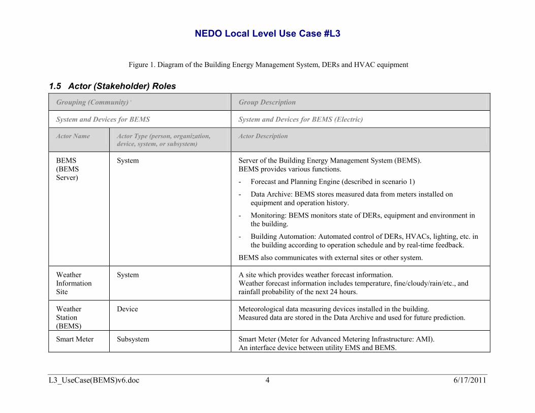
Figure 1. Diagram of the Building Energy Management System, DERs and HVAC equipment
1.5 Actor (Stakeholder) Roles
Grouping (Community) , Group Description
System and Devices for BEMS System and Devices for BEMS (Electric)
Actor Name Actor Type (person, organization, device, system, or subsystem)
Actor Description
BEMS (BEMS Server)
System Server of the Building Energy Management System (BEMS). BEMS provides various functions.
- Forecast and Planning Engine (described in scenario 1)
- Data Archive: BEMS stores measured data from meters installed on equipment and operation history.
- Monitoring: BEMS monitors state of DERs, equipment and environment in the building.
- Building Automation: Automated control of DERs, HVACs, lighting, etc. in the building according to operation schedule and by real-time feedback.
BEMS also communicates with external sites or other system.
Weather Information Site
System A site which provides weather forecast information. Weather forecast information includes temperature, fine/cloudy/rain/etc., and rainfall probability of the next 24 hours.
Weather Station (BEMS)
Device Meteorological data measuring devices installed in the building. Measured data are stored in the Data Archive and used for future prediction.
Smart Meter Subsystem Smart Meter (Meter for Advanced Metering Infrastructure: AMI). An interface device between utility EMS and BEMS.

NEDO Local Level Use Case #L3
L3_UseCase(BEMS)v6.doc 5 6/17/2011
Grouping (Community) , Group Description
System and Devices for BEMS System and Devices for BEMS (Electric)
Actor Name Actor Type (person, organization, device, system, or subsystem)
Actor Description
Smart Meter receives DR signals from utility EMS and transmits them to BEMS.
Gas Engine (GE)
Subsystem Gas Engine generates electric power and heat. Exhaust heat is recovered as heat source for HVAC system.
Fuel Cell (FC)
Subsystem Fuel Cell (Phosphorous Acid Type) FC generates electric power heat by chemical reaction with Oxygen and Hydrogen. Hydrogen is extracted from city gas. Exhaust heat is recovered as heat source for HVAC system.
Battery Subsystem Lead-Acid Battery: A storage device which charges and discharges electrical energy. BEMS controls output (charge and discharge) of the battery via controllable inverter between battery and power line in the building.
PV Subsystem PV: Polycrystalline type Photovoltaic Panel installed on the building’s premises.
BEMS Electric Meter at PCC
Device Measuring device of electric power flow at the point of common coupling. This data are used by BEMS. Existing electric charging meter for power utilities is installed separately from this meter.
Protective Relay
Device A device which sends a cut-off signal to the circuit breakers when there are malfunctions in the building system or in the utility line such as power failures. It is installed with the purpose of protecting the system and devices
BEMS Operator
Person Person operates BEMS console.

NEDO Local Level Use Case #L3
L3_UseCase(BEMS)v6.doc 6 6/17/2011
Grouping (Community) , Group Description
System and Devices for BEMS System and Devices for BEMS (Electric)
Actor Name Actor Type (person, organization, device, system, or subsystem)
Actor Description
Synchronous Device
Device Synchronous Device (SD). When SD is activated during islanding mode, it watches the voltage, frequency and phase of both the utility line side and the building side separately. SD automatically closes CB when they are synchronized.
Grouping (Community) , Group Description
System and Devices for HVACs System and Devices for HVACs controlled by BEMS.
Actor Name Actor Type (person, organization, device, system, or subsystem)
Actor Description
Absorption Refrigerator (AR)
Subsystem Absorption Refrigerator. A device which driven by hot water to generate chilled water. In this use case, hot water is provided from GE and FC.
Air Cooled Chiller
Subsystem Air cooled chiller. A device which generates chilled water.
Thermal Storage (H)
Subsystem Thermal energy storage tank of hot water. It temporarily stores hot water generated by GE and FC.
Thermal Storage (C)
Subsystem Thermal energy storage tank of chilled water. It temporarily stores chilled water generated by AR and Air cooled chiller.
Heat Subsystem Heat exchanger between Thermal Storage (H) and existing HVAC system of the

NEDO Local Level Use Case #L3
L3_UseCase(BEMS)v6.doc 7 6/17/2011
Grouping (Community) , Group Description
System and Devices for HVACs System and Devices for HVACs controlled by BEMS.
Actor Name Actor Type (person, organization, device, system, or subsystem)
Actor Description
Exchanger (HEX)
building.
AHU+HP (DX)
Device Air Handling Unit + Heat Pump (Direct Expansion)
Existing air conditioning devices. Cold air or warm air from AHU (new) is delivered to this AHU+HP (DX).
AHU (new) Device Air Handling Unit (newly installed) It uses chilled water from thermal storage (C) to send cold air to intake of DX. It uses hot water from thermal storage (H) to send hot air to intake of DX.
1.6 Information exchanged
Information Object Name Information Object Description
Weather forecast information Weather data provided from Weather Information Site. Weather information (temperature, fine/cloudy/rain/snow/etc.) of next 24 hours at intervals of n hours. (n = 1, 3, 6, etc. Default is 3.)
DR Signals Demand Response signal from utility EMS to BEMS via Smart Meter. This signal includes following information.
(1) DR Index: Index for Demand Response indicating electricity price, reserve power, etc.

NEDO Local Level Use Case #L3
L3_UseCase(BEMS)v6.doc 8 6/17/2011
Information Object Name Information Object Description
(2) Flag: Operation mode request such as demand reduction, islanding and restoration.
GE output command Command signal to set GE output value (active power [W]). (from BEMS to GE)
GE output value Active power output of GE [W]. (from power meter on GE to BEMS)
FC output command Command signal to set FC output value (active power [W]). (from BEMS to FC)
FC output value Active power output of FC [W]. (from power meter on FC to BEMS)
Battery control command Command signal to set Battery output value (active power [W], reactive power [Var]). (from BEMS to Battery PCS)
Battery state value Active power [W], reactive power [Var] and state of charge (SOC) [%] of Battery. (from meter on Battery PCS to BEMS)
PV output value Active power output of PV [W]. (from power meter on PV PCS to BEMS)
Heat quantity from GE Temperature and flow rate of hot water generated by GE exhaust heat. (from thermometer and flow meter on GE to BEMS)
Heat quantity from FC Temperature and flow rate of hot water generated by FC exhaust heat. (from thermometer and flow meter on FC to BEMS)
Air Cooled Chiller output command
Command signal to set output level of Air Cooled Chiller (On/Off, output [%]). (from BEMS to Air Cooled Chiller)
Heat quantity from Air Cooled Temperature and flow rate of chilled water generated by Air Cooled Chiller.

NEDO Local Level Use Case #L3
L3_UseCase(BEMS)v6.doc 9 6/17/2011
Information Object Name Information Object Description
Chiller (from thermometer and flow meter on Air Cooled Chiller to BEMS)
AR output command Command signal to control Absorption Refrigerator (On/Off). (from BEMS to AR)
Heat quantity from AR Temperature and flow rate of chilled water generated by AR. (from thermometer and flow meter on AR to BEMS)
Stored heat of Thermal Storage (H) Stored thermal energy of Thermal Storage (H). Multipoint temperature in the tank is used for calculation of energy [MJ] by BEMS.
Stored heat of Thermal Storage (C) Stored thermal energy of Thermal Storage (C). Multipoint temperature in the tank is used for calculation of energy [MJ] by BEMS.
Heat quantity from Thermal Storage (H) to HEX
Temperature and flow rate of hot water sent from Thermal Storage (H) to HEX.
Heat quantity from Thermal Storage (H) to AHU
Temperature and flow rate of hot water sent from Thermal Storage (H) to AHU (new).
Heat quantity from Thermal Storage (C) to AHU
Temperature and flow rate of chilled water sent from Thermal Storage (C) to AHU (new).
1.7 Activities/Services Describe or list the activities and services involved in this Function (in the context of this Function). An activity or service can be provided by a computer system, a set of applications, or manual procedures. These activities/services should be described at an appropriate level, with the understanding that sub-activities and services should be described if they are important for operational issues, automation needs, and implementation reasons. Other sub-activities/services could be left for later analysis.

NEDO Local Level Use Case #L3
L3_UseCase(BEMS)v6.doc 10 6/17/2011
Activity/Service Name Activities/Services Provided
1.8 Contracts/Regulations Identify any overall (human-initiated) contracts, regulations, policies, financial considerations, engineering constraints, pollution constraints, and other environmental quality issues that affect the design and requirements of the Function.
Contract/Regulation Impact of Contract/Regulation on Function
Policy
From Actor
May Shall Not
Shall Description (verb) To Actor
Constraint Type Description Applies to
1.9 Terms and Acronyms
Term Definition

NEDO Local Level Use Case #L3
L3_UseCase(BEMS)v6.doc 11 6/17/2011
Acronym Definition
BEMS Building Energy Management System
CB Circuit Breaker
DER Distributed Energy Resource
DR Demand Response
FC Fuel Cell
GE Gas Engine generator
PCC Point of Common Coupling
PV Photovoltaic
SOC State of Charge
TOU Time-of-Use
AHU Air Handling Unit
DX Direct Expansion
HEX Heat Exchanger
HP Heat Pump

NEDO Local Level Use Case #L3
L3_UseCase(BEMS)v6.doc 12 6/17/2011
2 Step by Step Analysis of Function
2.1 Steps to implement function – Scenario 1: Forecasting and Scheduling BEMS makes the next day's operation plan for DERs and HVACs which optimizes economic efficiency, based on Time-of-Use (TOU) from the Smart Meter, weather forecast information and building's past environmental information, and equipment operational performance data.
2.1.1 Preconditions and Assumptions Actor/System/Information/Contract Preconditions or Assumptions
BEMS (Data Archive) BEMS has forecast function, scheduling function, data accumulation function, and building automation function.
BEMS stores past performance data such as measured data (power, temperature, etc.), operation history (schedule and actual control signals) in the Data Archive which is accessed from each function.
Smart Meter Utility EMS, Smart Meter and BEMS are networked and all signals between Utility EMS and BEMS can be exchanged via Smart Meter.
DERs (GE, FC, Battery) Each energy resource is connected to the building power line. BEMS can control and monitor output of each DER.

NEDO Local Level Use Case #L3
L3_UseCase(BEMS)v6.doc 13 6/17/2011
2.1.2 Steps
# Event Primary Actor Name of Process/Activity
Description of Process/Activity
Information Producer
Information Receiver
Name of Info Exchanged Additional Notes IECSA
Environment
1.1A Schedule (by 10 p.m.)
BEMS Retrieves weather forecast information
BEMS retrieves next day’s weather forecast information from Weather Information Site and stores it in the Data Archive.
Weather Information Site
BEMS The next day’s 24 hour weather forecast info (fine/cloudy/rain) and temperature.
1.1B Schedule (by 10 p.m.)
BEMS Receives TOU information
BEMS retrieves next day’s TOU information from Smart Meter and stores it in the Data Archive.
Smart Meter BEMS TOU price index
1.2.1A
BEMS retrieved Weather and TOU information
BEMS Thermal Load prediction
BEMS predicts hourly thermal load (required supply heat quantity) of daytime of the next day.
BEMS BEMS Weather forecast info and past performance data stored in the Data Archive
1.2.1B
BEMS retrieved Weather information
BEMS PV output prediction
BEMS predicts hourly PV output of the next day.
BEMS BEMS Weather forecast info and past performance data stored in the Data Archive
1.2.2 Thermal load prediction and PV output prediction finished
BEMS BEMS solves an optimization problem of DERs and HVACs operation schedule
BEMS solves a demand optimization problem of DERs and HVACs operation schedule with given constraint conditions (cost minimum, etc.)
BEMS BEMS TOU information, PV output, thermal load, past performance, characteristic of DERs and HVACs.
1.2.3 DER and HVAC operation schedule was determined
BEMS Operation schedule registration
BEMS registers next 24 hour schedule for DERs and HVACs
BEMS BEMS The next day’s operation schedule for DERs and HVACs

NEDO Local Level Use Case #L3
L3_UseCase(BEMS)v6.doc 14 6/17/2011
2.1.3 Post-conditions and Significant Results
Actor/Activity Post-conditions Description and Results
BEMS BEMS has predicted next day’s PV output based on weather forecast data. BEMS has predicted next day’s building’s thermal load and required supply heat quantity. The next day’s operation schedule for DERs and HVACs has been determined. The next day’s operation schedule for DERs and HVACs has been registered on the BEMS control schedule.

NEDO Local Level Use Case #L3
L3_UseCase(BEMS)v6.doc 15 6/17/2011
2.2 Steps to implement function – Scenario 2: Demand Response Control in connected mode While operating according to the operation schedule of Scenario 1, BEMS receives a DR signal for demand reduction via Smart Meter. Then, BEMS controls DERs and HVACs in order to meet the request of DR.
2.2.1 Preconditions and Assumptions Actor/System/Information/Contract Preconditions or Assumptions
BEMS (Control) The DERs and HVAC equipment in the building are in operation according to the optimized schedule calculated in scenario 1.
All DERs are in operation (GE and FC are generating power). BEMS recognizes the current state of all DERs and HVACs.
BEMS (Monitoring) BEMS monitors output power [W] of each DER in real time (every one second). BEMS monitors power flow at PCC [W] in real time (every one second). Measurement interval of other data may vary according to the type of equipment and measurement items.
BEMS (Data Archive) Characteristics of HVAC equipment such as response time, output level and consumed power are known and are stored in the Data Archive as a correspondence table.
BEMS and HVACs BEMS has demand response mode for HVAC control. In this mode, BEMS watches demand power flow at PCC and controls HVACs based on the correspondence table in order to keep the power flow at PCC within the allowable range that meets the DR request.

NEDO Local Level Use Case #L3
L3_UseCase(BEMS)v6.doc 16 6/17/2011
2.2.2 Steps
# Event Primary Actor Name of Process/Activity
Description of Process/Activity
Information Producer
Information Receiver
Name of Info Exchanged Additional Notes IECSA
Environment
2.1A.1A
Every second BEMS Smart Meter monitoring
BEMS monitors Smart Meter Status
Smart Meter BEMS Status of DR signal reception
2.1A.1B
Every second BEMS BEMS Electric Meter at PCC monitoring
BEMS monitors demand power at PCC
BEMS Electric Meter at PCC
BEMS Power [W]
2.1A.1C
Every second BEMS GE output monitoring
BEMS monitors output power of GE
Meter on GE BEMS Power [W]
2.1A.1D
Every second BEMS FC output monitoring
BEMS monitors output power of FC
Meter on FC BEMS Power [W]
2.1A.1E
Every second BEMS Battery power monitoring
BEMS monitors power flow of Battery
Meter on Battery PCS
BEMS Active Power [W] Reactive Power [Var] SOC [%]
2.1B.1
Utility EMS sent a DR signal to Smart Meter
BEMS DR signal for demand reduction
BEMS retrieves a DR signal for demand reduction from Smart Meter
Smart Meter BEMS DR signal (Flag: DR mode, Time: start time, Demand target: [W])
2.1B.2A
BEMS retrieved a DR signal
BEMS Saving current state for restoration
BEMS saves the current state of HVACs operation for restoration at DR end time.
BEMS BEMS Output setting value of each HVAC equipment
2.1B.2B
BEMS retrieved a DR signal
BEMS Mode change of HVACs control
BEMS changes control mode for HVACs from schedule mode to demand response mode
BEMS BEMS Mode change command
2.1B.2C
BEMS retrieved a DR signal
BEMS Determine the target of demand power and required power to be reduced
BEMS calculates and determines the target of demand power and required power to be reduced
BEMS BEMS Current power at PCC [W]

NEDO Local Level Use Case #L3
L3_UseCase(BEMS)v6.doc 17 6/17/2011
# Event Primary Actor Name of Process/Activity
Description of Process/Activity
Information Producer
Information Receiver
Name of Info Exchanged Additional Notes IECSA
Environment
2.1B.3
BEMS determined required power to be reduced
BEMS Determine output value of each DER
BEMS determines output value of GE, FC, and Battery.
BEMS BEMS Current output value of DERs, New output value of DERs
2.1B.4A
BEMS determined output value of DERs
BEMS Output command to GE
BEMS sends output command to GE
BEMS GE Active power [W]
2.1B.4B
BEMS determined output value of DERs
BEMS Output command to FC
BEMS sends output command to FC
BEMS FC Active power [W]
2.1B.4C
BEMS determined output value of DERs
BEMS Output command to Battery
BEMS sends output command to Battery PCS
BEMS Battery PCS Active power [W]
2.1B.5
BEMS sent output command to DERs
BEMS Check demand power
BEMS checks demand power for DR requirement
BEMS BEMS Current demand power, Target demand power
if demand does not meet DR requirement, go to 2.1B.3
2.2.3 Post-conditions and Significant Results
Actor/Activity Post-conditions Description and Results
BEMS controls DERs and HVACs to meet DR requirement
BEMS continues controlling DERs and HVACs to meet requirement of DR signal until different DR signal is received.

NEDO Local Level Use Case #L3
L3_UseCase(BEMS)v6.doc 18 6/17/2011
2.3 Steps to implement function – Scenario 3: Islanding Operation While operating in demand response (demand reduction) mode of scenario 2, BEMS receives a DR signal for islanding operation via Smart Meter. Then, BEMS switches to islanding mode. Control of DERs in islanding mode and transition to connected mode are also discussed.
2.3.1 Preconditions and Assumptions Actor/System/Information/Contract Preconditions or Assumptions
BEMS BEMS controls DERs and HVACs in DR (demand reduction) mode described in scenario 2.
2.3.2 Steps
# Event Primary Actor Name of Process/Activity
Description of Process/Activity
Information Producer
Information Receiver
Name of Info Exchanged Additional Notes IECSA
Environment
3.1 Utility EMS sent a DR signal to Smart Meter
BEMS DR signal for islanding received
BEMS retrieves a DR signal for islanding from Smart Meter
Smart Meter BEMS DR signal (Flag: DR mode, Time: start time)
3.2.1A
Get to the start time for islanding
BEMS BEMS sends CB@PCC a cut-off signal
BEMS sends CB@PCC a cut-off signal to open the main breaker at PCC
BEMS CB at PCC Cut-off signal
3.2.1B
Get to the start time for islanding
BEMS Switch from connected mode to islanding mode
BEMS sends each DER to switch operation mode from connected mode to islanding mode.
BEMS GE, FC, Battery Switch command to islanding mode
3.3.1A
Every second BEMS GE output monitoring
BEMS monitors output power of GE
Meter on GE BEMS Power [W]
3.3.1B
Every second BEMS FC output monitoring
BEMS monitors output power of FC
Meter on FC BEMS Power [W]

NEDO Local Level Use Case #L3
L3_UseCase(BEMS)v6.doc 19 6/17/2011
# Event Primary Actor Name of Process/Activity
Description of Process/Activity
Information Producer
Information Receiver
Name of Info Exchanged Additional Notes IECSA
Environment
3.3.1C
Every second BEMS Battery output monitoring
BEMS monitors output power and SOC of Battery
Meter on Battery PCS
BEMS Power [W]
SOC [%]
3.3.2A
Every second BEMS Output command to FC
BEMS calculates FC output from each DER output and sends a control signal.
BEMS FC Power [W]
3.3.2B
Every second BEMS Output command to Battery
BEMS calculates Battery output from each DER output and sends a control signal.
BEMS Battery PCS Power [W]
3.4.1 Utility EMS sent
a DR signal to Smart Meter
BEMS DR signal for connected mode received
BEMS retrieves a DR signal for connected mode from Smart Meter
Smart Meter BEMS DR signal (Flag: DR mode)
3.4.2 BEMS retrieved a DR signal for connected mode
BEMS (console) BEMS shows prompt for connected mode
BEMS shows that the utility line is ready and prompt for connected mode on the console.
BEMS (console) BEMS Operator Prompt screen for return to connected mode
3.4.3 BEMS Operator recognized information on the BEMS console
BEMS Operator Send command to activate synchronous device
BEMS Operator operates console to switch from islanding mode to connected mode.
BEMS Operator BEMS (console) Operation command to return to connected mode
3.4.4 BEMS accept command for connected mode
BEMS BEMS activates Synchronous device
BEMS sends a command and activate Synchronous device.
BEMS Synchronous device
Synchronous device activation command signal
SD automatically closes CB at PCC when both sides are synchronized.
3.4.5 CB@PCC closed BEMS Switch from islanding mode to connected mode
BEMS sends each DER to switch operation mode from islanding to connected mode.
BEMS GE, FC, Battery Switch command to connected mode

NEDO Local Level Use Case #L3
L3_UseCase(BEMS)v6.doc 20 6/17/2011
2.3.3 Post-conditions and Significant Results
Actor/Activity Post-conditions Description and Results
1. Switch to islanding mode CB at PCC is opened and each DER's operating mode switches to islanding mode.
2. Performance during islanding mode
BEMS watches each DER's output and controls them to stabilize voltage and frequency of the power line in the building.
3. Switch to connected mode CB at PCC is closed and each DER's operating mode switches to connected mode.
2.4 Architectural Issues in Interactions
2.5 Diagram
3 Auxiliary Issues
3.1 References and contacts
ID Title or contact Reference or contact information
[1] Cooperative control among μEMS, Battery system and BEMS
[2]

NEDO Local Level Use Case #L3
L3_UseCase(BEMS)v6.doc 21 6/17/2011
3.2 Action Item List
ID Description Status
[1]
[2]
3.3 Revision History
No Date Author Description
0.1 12-1-2010 Yuji Yamamoto Noriyuki Odajima
Draft for the first review
1.0 12-27-2010 Yuji Yamamoto Eisuke Shimoda
All scenarios were added
2.0 1-5-2011 Yuji Yamamoto Atsushi Denda Kimio Morino
Revisions for review of the 2nd Use Case Meeting
3.0 1-19-2011 J. Manuel Barrera William M. Knuff Jon Hawkins Andrea Mammoli Marvin Cook
Overall Review and comments for 3rd meeting
4.0 1-28-2011 Yuji Yamamoto Revisions for review of the 3rd Use Case Meeting
5.0 2-28-2011 Yuji Yamamoto Atsushi Denda
Revisions for review by EPRI

NEDO Local Level Use Case #L3
L3_UseCase(BEMS)v6.doc 22 6/17/2011
No Date Author Description
Kimio Morino
6.0 5-18-2011 Yuji Yamamoto Revisions for Generic Use Case