1. drill a i/8” pilot hole in the top right hand...
TRANSCRIPT

#G7200 GATE INSTRUCTIONS – FOR #7200 LADDER
PARTS: 1-GATE 2-HINGE BRACKET1-LATCH1-LATCH PLATE
5- ¼-20 X 2- 1/4” BOLTS5- ¼-20 HEX NUT5- ¼-20 WASHERS1 -1/4-20 PLASTIC ACORN NUT
1 - PADLOCK1 - #10 x 1-1/4” SCREW
TO0LS REQUIRED: CORDLESS DRILL, 5/16” DRILL BIT, PHILLIPS SCREWDRIVER, 9/16” OPEN END WRENCH
NOTE: 7200 LADDER MUST BE ASSEMBLED AND ATTACHED TO POOL BEFORE GATE IS ATTACHED. SLIDE ROLL-GUARD TO INSIDE
Push the four 2-1/4” bolts through the pre-drilled holes located on the “OR” outside right ladder leg. You may need to tap head of bolts to knock out plastic.
Place washer over each bolt and start the ¼” x 20 hex nut
Slide the bottom hinge bracket up on to the bolts and tighten asecurely.
Confer Plastics97 Witmer RoadNorth Tonawanda NY 14120www.conferplastics.com
Made in USA
Printed in USA3-00-7200 G7200-Gate-8/13
FIRST INSTALL THE 7200 GATE AS PER THE INSTRUCTIONS.
FIGURE 1 FIGURE 2 FIGURE 3
1. DRILL A I/8” PILOT HOLE IN THE TOP RIGHT HAND CORNER OF THE SECOND TREAD. SEE FIGURE 1.
2. PLACE A ¼� WASHER OVER THE #10 X 1-1/4� SCREW AND INSERT THROUGH THE OPEN LOOP AT THE END OF THE TENSION BAND. SEE FIGURE 2.
3. WITH THE GATE PARTIALLY OPEN [LEAVING SLACK IN THE CORD] INSTALL THE TENSION BAND ONTO THE TOP OF THE SECOND TREAD BY THREADING THE SCREW INTO THE PILOT HOLE. TIGHTEN USING A PHILLIPS SCREWDRIVER. SEE FIGURE 3.
Confer ID3.indd 1 9/11/13 11:28:20 AM
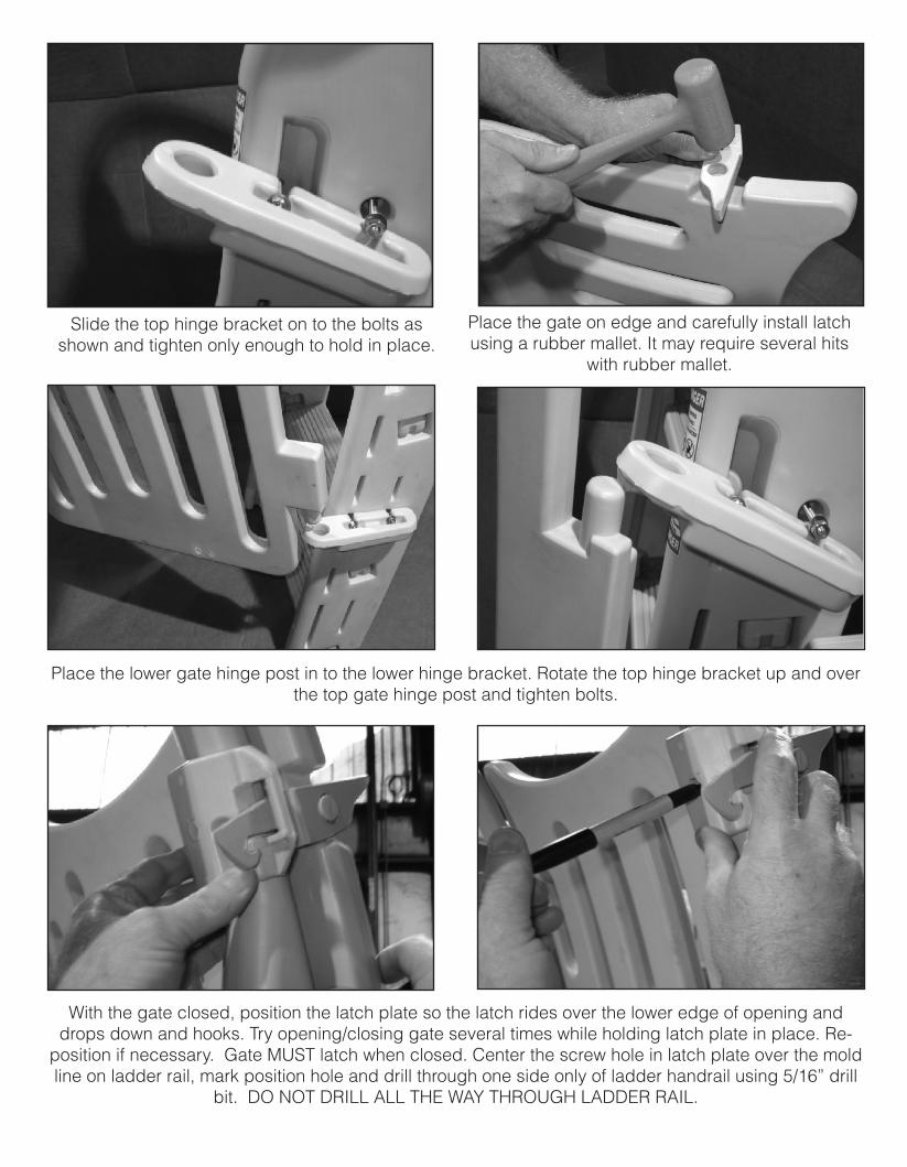
Slide the top hinge bracket on to the bolts as shown and tighten only enough to hold in place.
Place the gate on edge and carefully install latch using a rubber mallet. It may require several hits
with rubber mallet.
Place the lower gate hinge post in to the lower hinge bracket. Rotate the top hinge bracket up and over the top gate hinge post and tighten bolts.
With the gate closed, position the latch plate so the latch rides over the lower edge of opening and drops down and hooks. Try opening/closing gate several times while holding latch plate in place. Re-
position if necessary. Gate MUST latch when closed. Center the screw hole in latch plate over the mold line on ladder rail, mark position hole and drill through one side only of ladder handrail using 5/16” drill
bit. DO NOT DRILL ALL THE WAY THROUGH LADDER RAIL.
Push ¼-20 x 2-1/4� bolt through hole from front side of ladder, place hinge plate with ¼- 20 hex nut over bolt and tighten. Thread the ¼� plastic acorn nut onto the end of the bolt. NOTE: Gate must be latched at
all times and locked when pool is not in use.
To properly align the outer hole in the ladder rail tightly wrap a piece of paper around the rail so the bottom edge of paper bisects the centerline of drilled hole. Mark location where edge of paper bisects mold line on
front of rail and drill using 5/16” drill.
Confer ID3.indd 2 9/11/13 11:28:23 AM

#G7200 GATE INSTRUCTIONS – FOR #7200 LADDER
PARTS: 1-GATE 2-HINGE BRACKET1-LATCH1-LATCH PLATE
5- ¼-20 X 2- 1/4” BOLTS5- ¼-20 HEX NUT5- ¼-20 WASHERS1 -1/4-20 PLASTIC ACORN NUT
1 - PADLOCK1 - #10 x 1-1/4” SCREW
TO0LS REQUIRED: CORDLESS DRILL, 5/16” DRILL BIT, PHILLIPS SCREWDRIVER, 9/16” OPEN END WRENCH
NOTE: 7200 LADDER MUST BE ASSEMBLED AND ATTACHED TO POOL BEFORE GATE IS ATTACHED. SLIDE ROLL-GUARD TO INSIDE
Push the four 2-1/4” bolts through the pre-drilled holes located on the “OR” outside right ladder leg. You may need to tap head of bolts to knock out plastic.
Place washer over each bolt and start the ¼” x 20 hex nut
Slide the bottom hinge bracket up on to the bolts and tighten asecurely.
Confer Plastics97 Witmer RoadNorth Tonawanda NY 14120www.conferplastics.com
Made in USA
Printed in USA3-00-7200 G7200-Gate-8/13
FIRST INSTALL THE 7200 GATE AS PER THE INSTRUCTIONS.
FIGURE 1 FIGURE 2 FIGURE 3
1. DRILL A I/8” PILOT HOLE IN THE TOP RIGHT HAND CORNER OF THE SECOND TREAD. SEE FIGURE 1.
2. PLACE A ¼� WASHER OVER THE #10 X 1-1/4� SCREW AND INSERT THROUGH THE OPEN LOOP AT THE END OF THE TENSION BAND. SEE FIGURE 2.
3. WITH THE GATE PARTIALLY OPEN [LEAVING SLACK IN THE CORD] INSTALL THE TENSION BAND ONTO THE TOP OF THE SECOND TREAD BY THREADING THE SCREW INTO THE PILOT HOLE. TIGHTEN USING A PHILLIPS SCREWDRIVER. SEE FIGURE 3.
Confer ID3.indd 1 9/11/13 11:28:20 AM