1 dv id id id id i idd d iu di hi
TRANSCRIPT
PERPUSTAKAAN UMP
1 DV ID ID ID ID I IDD D IU DI HI 0000080241
LEAD ACID BATTERY MANAGEMENT SYSTEM FOR SOLAR HARVESTING SYSTEM
SHAZRIL BIN SHAEDI
Report submitted in partial fulfilment of the requirements
for the award of the degree of
Bachelor of Mechatronics PW a
Faculty of Manufacturing Engineering
UNIVERSITEI MALAYSIA PAl-lANG
JUNE 2013
ABSTRACT
The first solar energy was introduced in this decade and from that time, there are many new solar technology equipment was made in vehicle, lighting and other. Since then, various technologies have emerged to make solar based technology equipment with battery or other. However there are still limitations on the development process especially in terms of the battery management technology which includes battery technology. The phrase battery management means differently to different people, for us, battery management is how to manage all the battery voltage to be all same together and not so far difference when in used. Generally the energy battery management system of a solar equipment system includes the requirement to ensure that electrical power flow from the Photovoltaic to the loads will be monitored and optimised. Load behaviour significantly affects the solar equipment especially the battery. Hence, proper load battery management strategy is important to draw maximum power from the Photovoltaic module. A maximum power point tracker device must be used between the photovoltaic module and battery to boost the battery charging rate. Some back up batteries are needed in the system to eliminate unexpected system shutdown. As a result, an appropriate system that is focus on lead acid battery should be determined at the design stage to ensure for optimum battery management system can be built.
iv
ABSTRAK
Teknologi yang menggunakan kuasa solar yang pertama telah diperkenalkan di dalam abad mi, bermulalah dari situ, terdapat banyak jenis peralatan yang menggunakan kuasa solar yang baru seperti kenderaan, pencahayaan dan lain lain. Semenjak dari itu juga, pelbagai jenis peralatan yang menggunakan teknologi solar dikeluarkan dengan menggunakan peralatan teknologi dengan bateri nya sendiri. Walaubagaimanapun, terdapat sedikit masalah di dalam pembangunan teknologi solar mi terutamanya di dalam teknologi pengurusan batteri yang termasuk di dalam teknologi bateri. Frasa pengurusan bateri diterjemahkan di dalam pelbagai versi dan maksud di dalam pelbagai lapisan masyarakat, tetapi bagi kita, pengurusan bateri adalah satu sistem untuk bagaimana kita mahu mengawal semua voltan bateri yang disambungkan secara siri dan tidak banyak beza perubahan voltan diantara bateri apabila digunakan. Secara umumnya, sistem teknologi pengurusan bateri termasuklah kehendak kepada untuk memastikan perjalanan kuasa dari panel solar kepada beban dapat dikawal dan diambil tahu. Beban yang dipasang dan tingkah laku beban boleh memberi kesan yang negatif kepada peralatan teknologi solar terutamanya bateri yang dipakai. Maka dengan itu, system pengurusan bateri yang terbaik perlulah dipakai untuk memberi kuasa penuh daripada panel solar. Pengesan maksimum perlu juga diguna diantara panel solar untuk menaikkan kesan pengecas untuk bateri. Bateri penyokong juga perlu di dalam sistem untuk mengurangkan kesan jika terjadinya kuasa sistem hilang secara tiba tiba atau tak disangka sangka. Iviaka dengan itu, satu sistem pengurusan bateni yang difokuskan kepada bateri lead asid mesti dibina untuk memastikan sistem pengurusan bated yang terbaik dapat dipakai.
TABLE OF CONTENT
PAGE
SUPERVISOR'S DECLARATION
STUDENT'S DECLARATION
ACKNOWLEDGEMENTS
ABSTRACT iv
ABSTRAK
TABLE OF CONTENTS
LIST OF TABLES
LIST OF FIGURES x
LIST OF SYMBOLS xiii
LIST OF ABBREVIATIONS xiv
CHAPTER 1 INTRODUCTION
1.1 Introduction
1.2 Background of Study 2
1.3 Problem Statement 2
1.4 Research Objectives 3
1.5 Research Questions 3
1.6 Research Hypothesis 4
1.7 Scope of Study 4
CHAPTER 2 LITERATURE REVIEW
2.1. Introduction 5
2.2. Battery Management System 5
2.3. Battery Monitoring 6
2.4. Integrated VRLA-Battery Management System 7
2.5. Battery Management System
2.6. Photovoltaic
2.7. Photovoltaic P-N Junction 9
Vi
2.8. Photovoltaic Charging System with MPPT 10
2.9. Energy Storage 11
2.10. Batteries Balance ii
2.11. Battery modelling 12
2.12. Cell Balancing 13
2.13. Battery management system with mosfet boost system 13
2.14. Summary 16
CHAPTER 3 METHODOLOGY
3.1 Introduction i
3.2 Flow Chart of Study 17
3.3 Flow Chart of Programming 18
3.3.1. Study BMS and solar energy (step 1) 18 3.3.2. PlC AT89C5 I and DIY Programmer Load (step 2) 19 3.3.3. Simulation on eagle software (step 3) 19 3.3.4. Design schematic and board on Eagle software (step 4) 20 3.3.5. Etching PCB board (step 5) 21 3.3.6. Do programming on assembler Obj to Hex
Programmer. (step 6) 22 3.3.7. Burn the program into PlC using DIY Programmer
Load. (step 7) 25 3.3.8. Design Model and the controller (step 8) 26 3.3.9. Implement and Demo the project (step 9) 26 3.3.10. Calculation (step 10) 27
3.4. Summary 27
CHAPTER 4 RESULT AND DISCUSSION
4.1 Introduction 28 4.2 Mechanical Part 29
4.2.1 Introduction 29 4.2.2 Costing 29 4.2.3 Dimension 29 4.2.4 Process 31
4.3 Electrical and Electronic Part 33 4.3.1 Introduction 33 4.3.2 Costing
VII
VIII
4.3.3 Circuit Diagram 34 4.3.4 Process 35
4.4 Programming Part 40
4.4.1 Process 40 4.4.2 Introduction 40
4.5 Data Analysis 44
4.5.1 Introduction 44 4.5.2 Result analysis voltage versus current with load
(l2 Volt DCMotor) 45 4.5.3 Result analysis voltage versus current without load 47
4.6 Summary 49
CHAPTER 5 CONCLUSION AND RECOMMENDATION
5.1 Conclusion 50
5.2 Recommendation 50
REFERENCES 52
APPENDICES
A Gantt Chart PSMl 53
B Gantt Chart PSM 2 54

LIST OF TABLES
Table No. Title Page
4.1. List of component's prices that used in this study 33
LIST OF FIGURES
Figure No. Title Page
2.1 SOC, SOH, and RUL estimation framework 6
2.2 Layer structure of battery monitoring generating battery Status information, battery management and energy management, And mutual data flow 7
2.3 Battery Management system task organization 8
2.4 Photovoltaic cell equivalent circuit 10
2.5 BMS mosfet boost system 14
2.6 Battery management system 14
2.7 Battery energy management system for measuring a Minimum battery voltage 15
2.8 Battery management system 15
2.9 Battery management system 16
3.1 Methodology flow chart 17
3.2 Programming flow chart 18
3.3 Battery Management system connection 18
3.4 DIY Programmer Load 19
3.5 Eagle software 19
3.6 Design circuit diagram 20
3.7 Design PCB Board 20
3.8 Etching PCB board 21
3.9 Software to transfer from obj to hex Atmel language 25
3.10 DIY Programmer kit 26
3.11 Hardware design 26
4.1. Isometric View 29
x
4.2. Top View 30
4.3. Front View 30
4.4. Side View 30
4.5. Aluminium L shape and solar panel 18 volt 31
4.6. Aluminium composite 32
4.7. Circuit box 32
4.8. Multisim 34
4.9. Eagle 34
4.10. Circuit diagram in Multisim 35
4.11. Circuit diagram in Eagle 36
4.12. Etching circuit board 36
4.13. Circuit diagram on laminated paper 37
4.14. finished circuit on etching board 37
4.15. Etching liquid form 38
4.16. Grinding process 38
4.17. Soldering process 39
4.18. Circuit with IC stand for at89c52 39
4.19. MIDE Studio for MCS-51 programming 40
4.20. flex file in MIDI Studio for MCS-51 43
4.21. DIY Flash programmer board 44
4.22. Result analysis current (1)
4.23. Result analysis voltage (v) 46
4.24. Analysis of current and voltage without load battery 1 47
4.25. Analysis of current and voltage without load battery 2 48
Xi

4.26. Analysis of current and voltage without load battery 3 49
XII
LIST OF SYMBOL
The discharge current (Ampere)
n The battery constant (n= 1 .35 for typical lead-acid batteries)
Ti The time to discharge at current I (Sec)
Cl, C2 The discharge rates at different discharge rate states
11, 12 The currents at the two different discharge rate states
V The voltage (Volt)
XIII
LIST OF ABBREVIATION
AB I After battery I
A132 After battery 2
A133 After battery 3
ASP After solar panel
BMS Battery management system
CPU Central Processing Unit
DC Direct current
EV Electric Vehicle
GSM Global System for Mobile Communications
HEV Hybrid Vehicle
IC Integrated circuit
LIPO Lithium-ion polymer batteries
MATLAB Matrix laboratory
MOSFET Metal-oxide semiconductor field effect transistor
MPP maximum power point
MPPT Maximum Power point tracking
PCB Printed circuit board
PEROM programmable and erasable read only memory
P-N Positive Negative
PV Photovoltaic
RC Radio-controller
RUL Remaining Useful Life
SOC State of charge
SOH State of health
xiv

VRLA valve-regulated lead—acid battery
xv
CHAPTER 1
INTRODUCTION
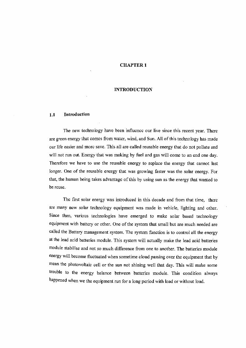
1.1 Introduction
The new technology have been influence our live since this recent year. There
are green energy that comes from water, wind, and Sun. All of this technology has made
our life easier and more save. This all are called reusable energy that do not pollute and
will not run out. Energy that was making by fuel and gas will come to an end one day.
Therefore we have to use the reusable energy to replace the energy that cannot last
longer. One of the reusable energy that was growing faster was the solar energy. For
that, the human being takes advantage of this by using sun as the energy that wanted to
be reuse.
The first solar energy was introduced in this decade and from that time, there
are many new solar technology equipment was made in vehicle, lighting and other.
Since then, various technologies have emerged to make solar based technology
equipment with battery or other. One of the system that small but are much needed are
called the Battery management system. The system function is to control all the energy
at the lead acid batteries module. This system will actually make the lead acid batteries
module stabilise and not so much difference from one to another. The batteries module
energy will become fluctuated when sometime cloud passing over the equipment that by
mean the photovoltaic cell or the sun not shining well that day. This will make some
trouble to the energy balance between batteries module. This condition always happened when we the equipment run for a long period with load or without load.
2
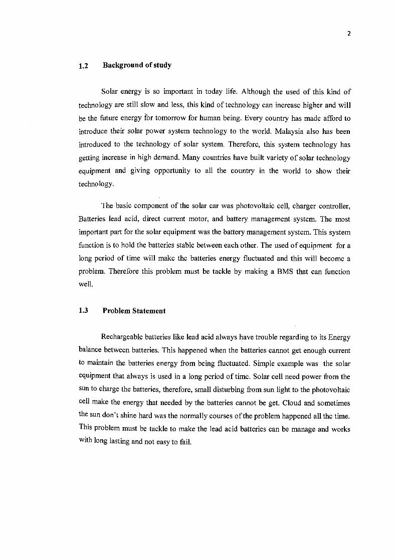
1.2 Background of study
Solar energy is so important in today life. Although the used of this kind of
technology are still slow and less, this kind of technology can increase higher and will
be the future energy for tomorrow for human being. Every country has made afford to
introduce their solar power system technology to the world. Malaysia also has been
introduced to the technology of solar system. Therefore, this system technology has
getting increase in high demand. Many countries have built variety of solar technology
equipment and giving opportunity to all the country in the world to show their
technology.
The basic component of the solar car was photovoltaic cell, charger controller,
Batteries lead acid, direct current motor, and battery management system. The most
important part for the solar equipment was the battery management system. This system
function is to hold the batteries stable between each other. The used of equipment for a
long period of time will make the batteries energy fluctuated and this will become a
problem. Therefore this problem must be tackle by making a BMS that can function
well.
1.3 Problem Statement
Rechargeable batteries like lead acid always have trouble regarding to its Energy
balance between batteries. This happened when the batteries cannot get enough current
to maintain the batteries energy from being fluctuated. Simple example was the solar
equipment that always is used in a long period of time. Solar cell need power from the
sun to charge the batteries, therefore, small disturbing from sun light to the photovoltaic
cell make the energy that needed by the batteries cannot be get. Cloud and sometimes
the sun don't shine hard was the normally courses of the problem happened all the time.
This problem must be tackle to make the lead acid batteries can be manage and works
with long lasting and not easy to fail.
3
1.4 Research Objective
i. To built a model of batteries management system that can manage the lead acid
batteries. This BMS can control and manage all the series of lead acid batteries
or other type of rechargeable battery in the world. This BMS can manage the
voltage with precise.
ii. To built a model that have input and output of simple system that was easy to
carry, easy to connect and friendly user. This BMS will make it easy to the
entire user that wanted to maintain and guard their lead acid batteries in solar
energy equipment like solar heater, solar car and other type of things that usually
used solar power.
iii. To build a model of BMS that can manage series of batteries rechargeable type
that always have fluctuated output on batteries. This BMS will protect, guard
and keep safe all the batteries and this will make it not easy to broken or fail.
1.5 Research Question
Today, the important of how to control and manage all the batteries in system
that used solar energy to produce voltage can be seen all in many sectors like industrial,
construction, electronic and automotive. Batteries that been used have many kinds of
weakness that must be tackle and settle it before it can be used with steady and always
in good condition. The difficulty happened when all the voltage in one of series of lead
acid or rechargeable batteries are not same org fluctuated between each other. Therefore
this will contribute to failing on the system all. Therefore a battery management system
must be made to tackle this entire problem.
i. How to control and manage the energy in all of the lead acid batteries ii. How to make sure that the battery management system can with stand all the
problem regarding to the batteries that not consistence in energy balance
iii. How to built and create a battery management system model that can be used
with long period and less problem
1.6 Research Hypothesis
Energy balance between batteries that being attach in series can be manage by
Install the Battery management system circuit that can control all the measurement Spec
in all of the batteries
1.7 Scope of Study
i. Battery management system for solar car or equipment. All the equipment that used
solar powered energy will need rechargeable batteries. This all batteries need a good
protector. There for this BMS will be the answer.
ii. Energy management for battery type lead acid and other type of rechargeable
batteries.
iii. PlC Programming AT89C52. This PlC will be used vastly in this BMS system. The
PlC will be programmed according to needs.
CHAPTER 2
LITERATURE REVIEW
2.1. Introduction
Energy balances in batteries are so important and must be consider and control
its behaviour. This chapter are focus on batteries management that used by the solar cell
as an input direct current. Therefore, a suitable battery management system module will
be creating to overcome this entire problem in management of the battery.
2.2. Battery Management System
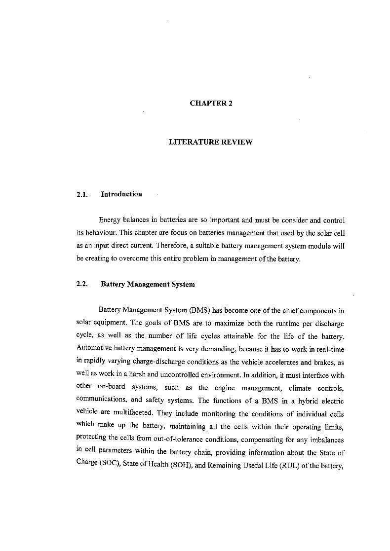
Battery Management System (BMS) has become one of the chief components in
solar equipment. The goals of BMS are to maximize both the runtime per discharge
cycle, as well as the number of life cycles attainable for the life of the battery.
Automotive battery management is very demanding, because it has to work in real-time
in rapidly varying charge-discharge conditions as the vehicle accelerates and brakes, as
well as work in a harsh and uncontrolled environment. In addition, it must interface with
other on-board systems, such as the engine management, climate controls, communications, and safety systems. The functions of a BMS in a hybrid electric
vehicle are multifaceted. They include monitoring the conditions of individual cells
which make up the battery, maintaining all the cells within their operating limits, protecting the cells from out-of-tolerance conditions, compensating for any imbalances
in cell parameters within the battery chain, providing information about the State of
Charge (SOC), State of Health (SOH), and Remaining Useful Life (RUL) of the battery,
6
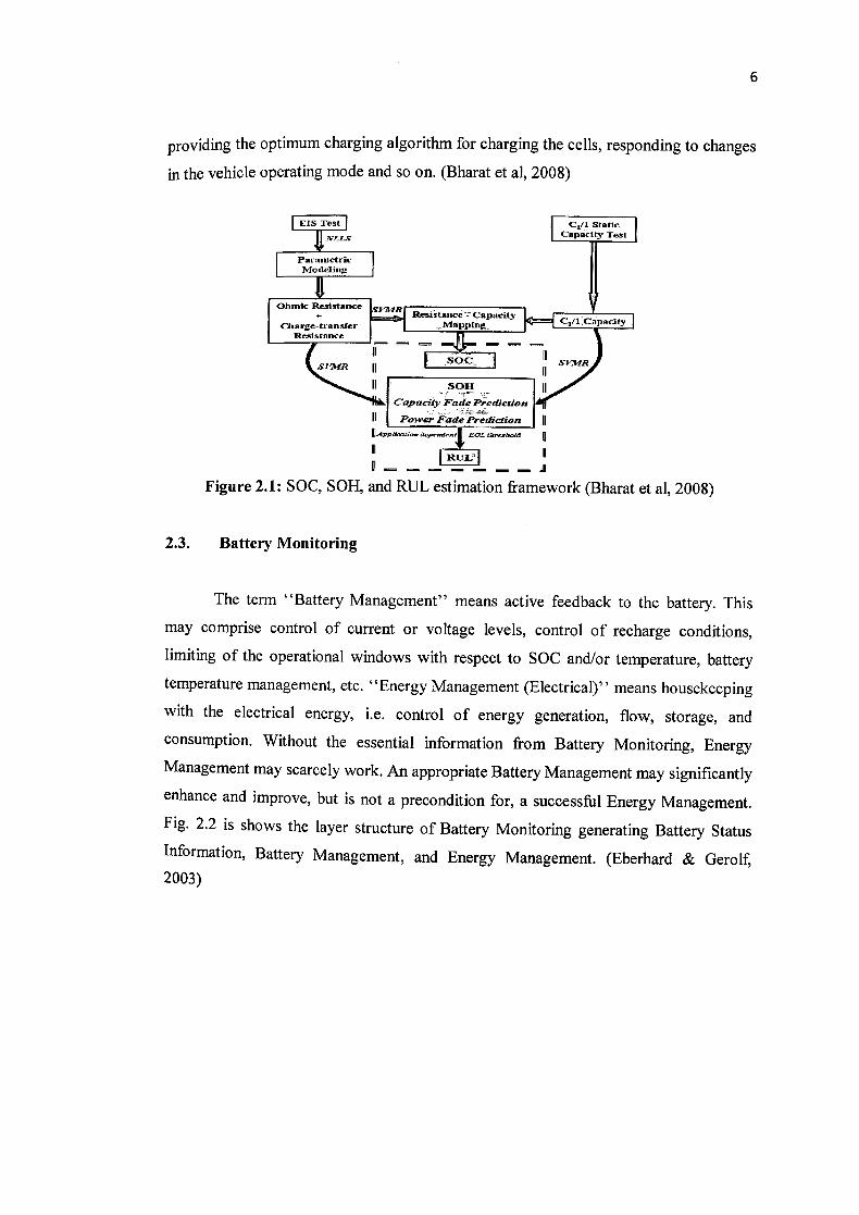
providing the optimum charging algorithm for charging the cells, responding to changes
in the vehicle operating mode and so on. (Bharat et al, 2008)
EIS Test
Cii Static
El
capacity Test
Parametric
ICharge transfer Rr3tstancc
SV
: -
II SOJ4 Capaci4 Fo!e F'idicrian
II
Power Fade Prediction IIAp:aE:ka
Figure 2.1: SOC, SOH, and RUL estimation framework (Bharat et al, 2008)
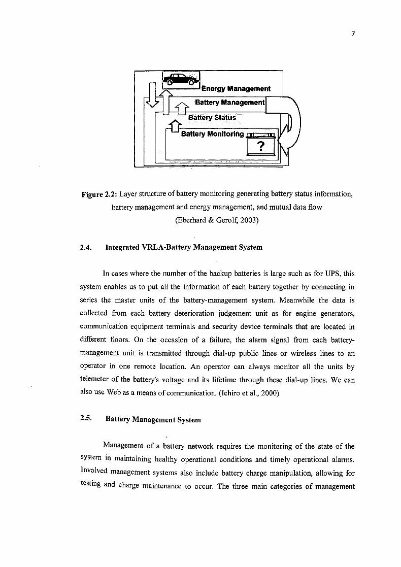
2.3. Battery Monitoring
The term "Battery Management" means active feedback to the battery. This
may comprise control of current or voltage levels, control of recharge conditions,
limiting of the operational windows with respect to SOC and/or temperature, battery
temperature management, etc. "Energy Management (Electrical)" means housekeeping
with the electrical energy, i.e. control of energy generation, flow, storage, and
consumption. Without the essential information from Battery Monitoring, Energy
Management may scarcely work. An appropriate Battery Management may significantly
enhance and improve, but is not a precondition for, a successful Energy Management.
Fig. 2.2 is shows the layer structure of Battery Monitoring generating Battery Status
Information, Battery Management, and Energy Management. (Eberhard & Gerolf, 2003)
7
Figure 2.2: Layer structure of battery monitoring generating battery status information,
battery management and energy management, and mutual data flow
(Eberhard & Gerolf, 2003)
2.4. Integrated VRLA-Battery Management System
In cases where the number of the backup batteries is large such as for UPS, this
system enables us to put all the information of each battery together by connecting in
series the master units of the battery-management system. Meanwhile the data is
collected from each battery deterioration judgement unit as for engine generators,
communication equipment terminals and security device terminals that are located in
different floors. On the occasion of a failure, the alarm signal from each battery-
management unit is transmitted through dial-up public lines or wireless lines to an
operator in one remote location. An operator can always monitor all the units by
telemeter of the battery's voltage and its lifetime through these dial-up lines. We can
also use Web as a means of communication. (Ichiro et al., 2000)
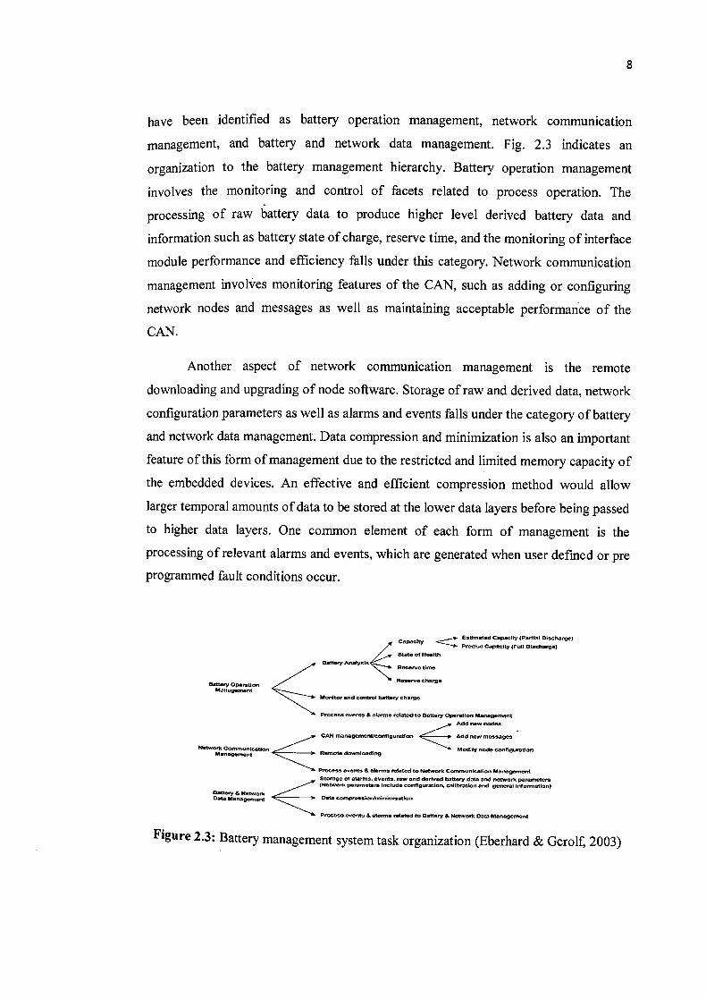
2.5. Battery Management System
Management of a battery network requires the monitoring of the state of the
system in maintaining healthy operational conditions and timely operational alarms.
Involved management systems also include battery charge manipulation, allowing for
testing and charge maintenance to occur. The three main categories of management
8
have been identified as battery operation management, network communication
management, and battery and network data management. Fig. 2.3 indicates an
organization to the battery management hierarchy. Battery operation management
involves the monitoring and control of facets related to process operation. The
processing of raw battery data to produce higher level derived battery data and
information such as battery state of charge, reserve time, and the monitoring of interface
module performance and efficiency falls under this category. Network communication
management involves monitoring features of the CAN, such as adding or configuring
network nodes and messages as well as maintaining acceptable performance of the
CAN.
Another aspect of network communication management is the remote
downloading and upgrading of node software. Storage of raw and derived data, network
configuration parameters as well as alarms and events falls under the category of battery
and network data management. Data compression and minimization is also an important
feature of this form of management due to the restricted and limited memory capacity of
the embedded devices. An effective and efficient compression method would allow
larger temporal amounts of data to be stored at the lower data layers before being passed
to higher data layers. One common element of each form of management is the
processing of relevant alarms and events, which are generated when user defined or pre
programmed fault conditions occur.
Estimated Capacity (Partial Diecherge) Capacity —< erecioc Capacity (Foil Diecharge) State Of Heelth
___w
charge
Battery Analycle.Reserve time
Oattery Operation Management
Monitor and control battery chrgo
Proceee eventS & Clartna related to Battery Operation Management
lOn< ::::::-
PrOcit eve nts & alannO related to Network Cmnmo,ticatlon Management Storage of alarms, events, raw and derived battery data and network parameters (Ntwo erk p me
Data
araters noted. configuration.. calibration and general lnfn,n.aticn)
Management S Data oO.npreeelonhninimiaatlon
Prococo events & -1—related to Battery & Network Data Managemont
Figure 2.3: Battery management system task organization (Eberhard & Gerolf, 2003)
9
2.6. Photovoltaic
Photovoltaic (PV) generation is becoming increasingly important as a renewable
source since it offers many advantages such as incurring no fuel costs, not being
polluting, requiring little maintenance, and emitting no noise, among others. PV arrays
produce electric power directly from sunlight. With the advent of silicon P-N junction
during the 1950s, .the photoelectric current was able to produce power due to the
inherent voltage drop across the junction. This gives the well-known nonlinear
relationship between the current and voltage of the photovoltaic cell. From this
nonlinear relationship of the photovoltaic cell, it can be observed that there is a unique
point, under given illumination, at which the cell produces maximum power, the so-
called maximum power point (MPP). This point occurs when the rate of change of the
power with respect to the voltage is equal to zero (Eberhard & Gerolf, 2003).
The output power of PV cell varies with depending mainly on the level of solar
radiation and ambient temperature corresponding to a specific weather condition. The
MPP will change with external environment of PV cell. An important consideration in
achieving high efficiency in PV power generation system is to match the PV source and
load impedance properly for any weather conditions, thus obtaining maximum power
generation. The technique process of maximum power point is been tracking which is
called maximum power point tracking (MPPT) (Jiyong & Honghua, 1998).
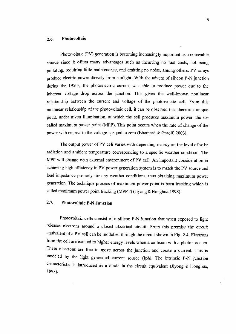
2.7. Photovoltaic P-N Junction
Photovoltaic cells consist of a silicon P-N junction that when exposed to light
releases electrons around a closed electrical circuit. From this premise the circuit
equivalent of a PV cell can be modelled through the circuit shown in Fig. 2.4. Electrons
fro m the cell are excited to higher energy levels when a collision with a photon occurs.
These electrons are free to move across the junction and create a current. This is
modeled by the light generated current source (Iph). The intrinsic P-N junction characteristic is introduced as a diode in the circuit equivalent (Jiyong & Honghua, 1998).
+
A ph 4 V
10
Figure 2.4: Photovoltaic cell equivalent circuit (David, 2012)
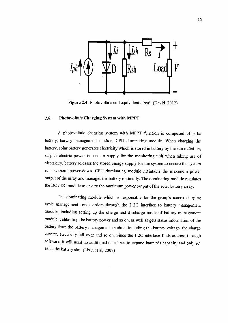
2.8. Photovoltaic Charging System with MPPT
A photovoltaic charging system with MPPT function is composed of solar
battery, battery management module, CPU dominating module. When charging the
battery, solar battery generates electricity which is stored in battery by the sun radiation,
surplus electric power is used to supply for the monitoring unit when taking use of
electricity, battery releases the stored energy supply for the system to ensure the system
runs without power-down. CPU dominating module maintains the maximum power
output of the array and manages the battery optimally. The dominating module regulates
the DC / DC module to ensure the maximum power output of the solar battery array.
The dominating module which is responsible for the group's macro-charging
cycle management sends orders through the I 2C interface to battery management
module, including setting up the charge and discharge mode of battery management
module, calibrating the battery power and so on, as well as gets status information of the
battery from the battery management module, including the battery voltage, the charge
current, electricity left over and so on. Since the I 2C interface finds address through
software, it will need no additional data lines to expand battery's capacity and only set
aside the battery slot. (Lixin et al, 2008)
11
2.9. Energy Storage
Energy storage for PV systems commonly consists of batteries to store and
discharge electrical energy as needed. However, each time a battery is charged or
discharged, some energy is lost from the system. Batteries vary by type, depth of
discharge, rate of charge, and lifetime (in PV applications). The most common types of
batteries used with PV systems are lead-acid, but other more exotic and expensive
batteries are sometimes used, such as nickel metal hydride. A new area of PV battery
applications is emerging in which the PV battery is used for backup power when the
utility grid fails for grid-tied PV systems. This application has unique battery charging
and maintenance requirements. Batteries are usually installed in well-ventilated
locations such as garages, utility rooms, and outbuildings to minimize the potential for
capturing explosive concentrations of hydrogen gas and to minimize possible hazards
from electrolyte spills. (Taylor & Francis, 2012)
2.10. Batteries Balance
Balancing is the most important concept concerning the life of the battery
system because without the balancing system, the individual cell voltages drift apart
over time. The capacity of the total pack also decreases more quickly during operation,
which results in the failure of the total battery system. This condition is especially
severe when the battery has a long string of cells (high-voltage battery systems) and
frequent regenerative braking (charging) is done via the battery pack. Imbalance of cells
in battery systems is very common and is the result of many sources. The sources fall
into two major categories such as internal and external. The internal sources include manufacturing variance in physical volume, variations in internal impedance, and differences in se lf-discharge rate. The external source is mainly caused by some multi rank pack protection ICs draining unequally from the different series ranks in the pack.
Thermal difference across the pack is another external source because it results in different self-discharge rates of the cells. Balancing methods can be either passive or active. Passive balancing method can only be used for lead acid and nickel-based batteries because lead-acid and nickel-based batteries can be brought into overcharge Conditions Without permanent cell damage. When the overcharge is not very severe, the