1 electronic fuel injection. electronic fuel injection system videoelectronic fuel injection system...
TRANSCRIPT
1
Electronic Fuel InjectionElectronic Fuel Injection
• Electronic Fuel Injection System VideoElectronic Fuel Injection System Video
2
3
Electronic Fuel InjectionElectronic Fuel Injection
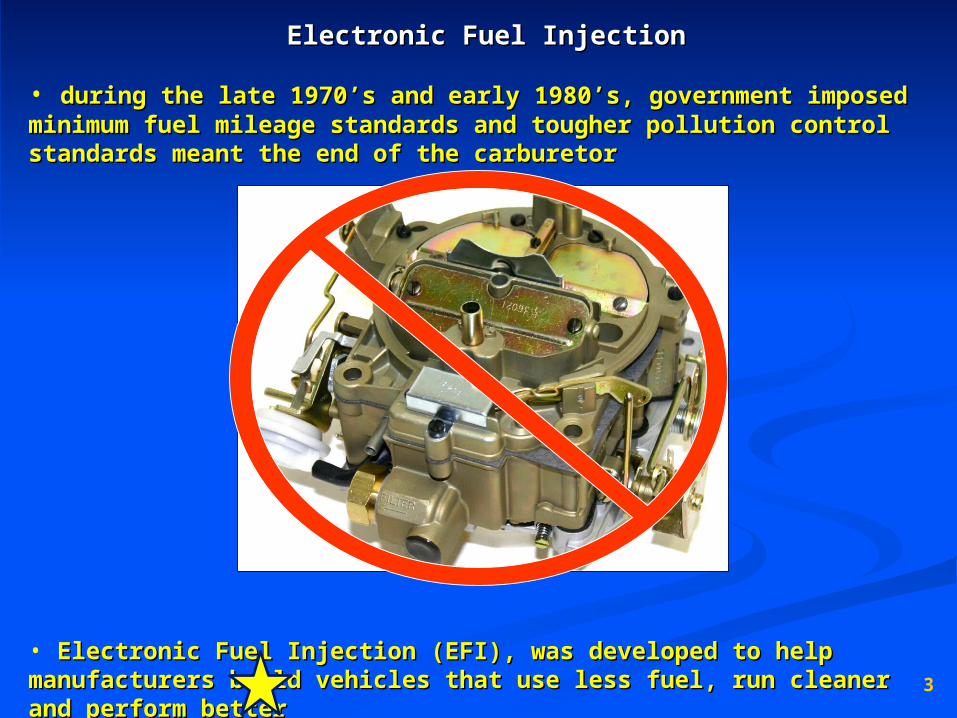
• during the late 1970’s and early 1980’s, government imposed during the late 1970’s and early 1980’s, government imposed minimum fuel mileage standards and tougher pollution control minimum fuel mileage standards and tougher pollution control standards meant the end of the carburetorstandards meant the end of the carburetor
• Electronic Fuel Injection (EFI), was developed to help Electronic Fuel Injection (EFI), was developed to help manufacturers build vehicles that use less fuel, run cleaner and manufacturers build vehicles that use less fuel, run cleaner and perform betterperform better
4
What is EFI?What is EFI?
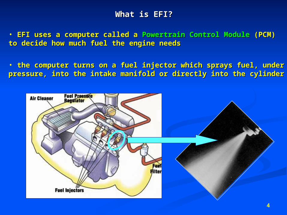
• EFI uses a computer called a EFI uses a computer called a Powertrain Control ModulePowertrain Control Module (PCM) to (PCM) to decide how much fuel the engine needs decide how much fuel the engine needs
• the computer turns on a fuel injector which sprays fuel, under the computer turns on a fuel injector which sprays fuel, under pressure, into the intake manifold or directly into the cylinderpressure, into the intake manifold or directly into the cylinder
5
3 main types of fuel injection…3 main types of fuel injection…
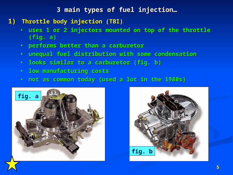
1)1) Throttle body injection (TBI)Throttle body injection (TBI)• uses 1 or 2 injectors mounted on top of the throttle (fig. a)uses 1 or 2 injectors mounted on top of the throttle (fig. a)• performs better than a carburetorperforms better than a carburetor• unequal fuel distribution with some condensationunequal fuel distribution with some condensation• looks similar to a carburetor (fig. b)looks similar to a carburetor (fig. b)• low manufacturing costslow manufacturing costs• not as common today (used a lot in the 1980s)not as common today (used a lot in the 1980s)
fig. a
fig. b
6
3 main types of fuel injection…3 main types of fuel injection…
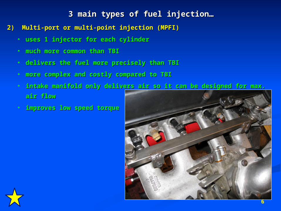
2) Multi-port or multi-point injection (MPFI)2) Multi-port or multi-point injection (MPFI)
• uses 1 injector for each cylinderuses 1 injector for each cylinder
• much more common than TBImuch more common than TBI
• delivers the fuel more precisely than TBIdelivers the fuel more precisely than TBI
• more complex and costly compared to TBImore complex and costly compared to TBI
• intake manifold only delivers air so it can be designed for max. air flowintake manifold only delivers air so it can be designed for max. air flow
• improves low speed torqueimproves low speed torque
7
3 main types of fuel injection…3 main types of fuel injection…
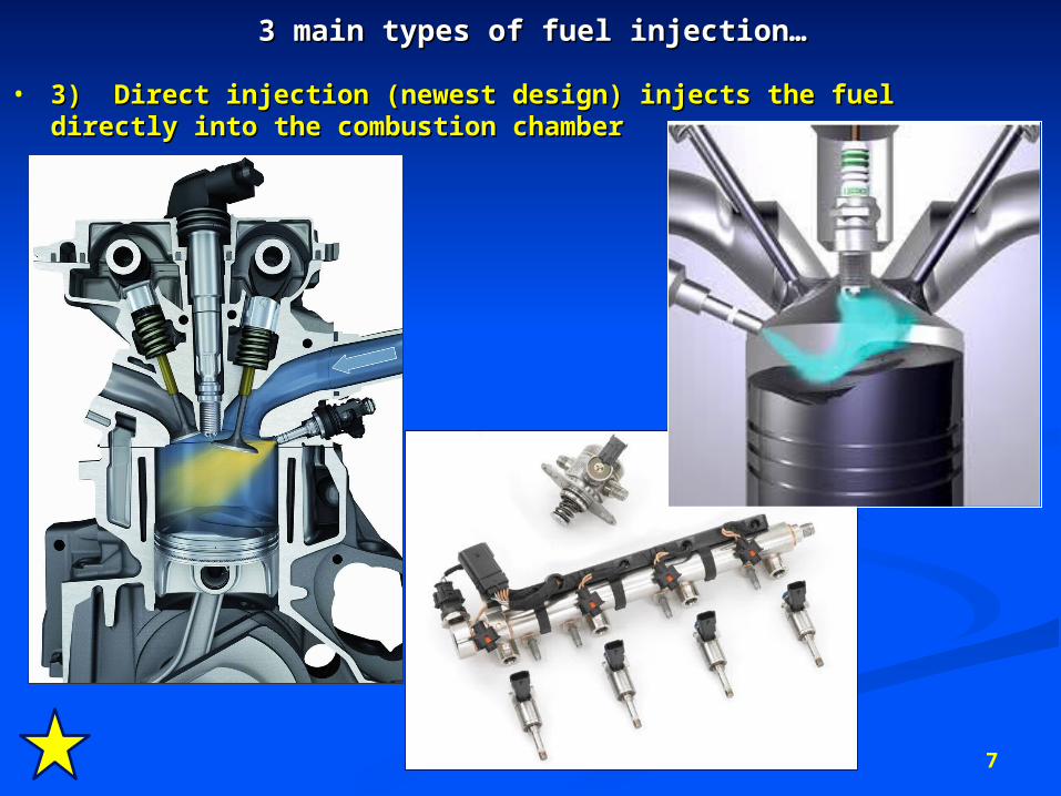
• 3) Direct injection (newest design) injects the fuel directly 3) Direct injection (newest design) injects the fuel directly into the combustion chamberinto the combustion chamber
8
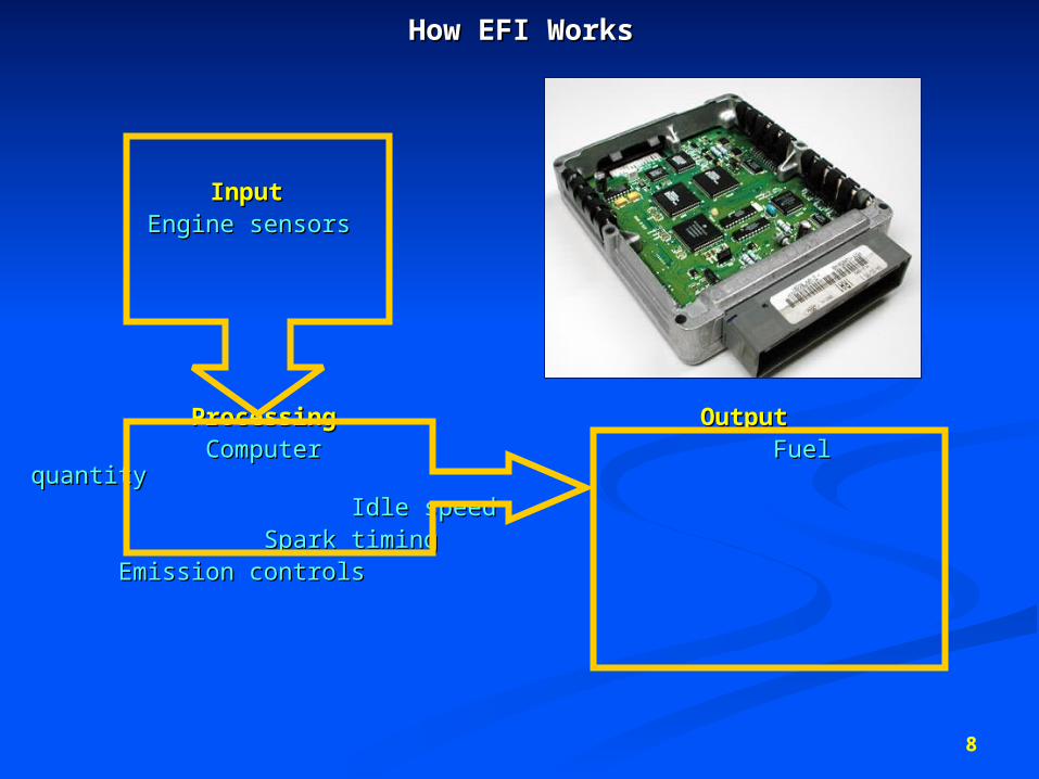
How EFI WorksHow EFI Works
InputInput Engine sensorsEngine sensors
ProcessingProcessing OutputOutput Computer Computer Fuel quantityFuel quantity
Idle speedIdle speed Spark timingSpark timing
Emission controlsEmission controls

9
10
Input SectionInput Section
• these sensors provide engine information to the PCM…these sensors provide engine information to the PCM…
engine speed sensor engine speed sensor
throttle position sensorthrottle position sensor
coolant temperature sensorcoolant temperature sensor
air temperature sensorair temperature sensor
engine load sensorengine load sensor
knock (detonation) sensorknock (detonation) sensor
oxygen sensoroxygen sensor
11
Input Section – Engine SpeedInput Section – Engine Speed
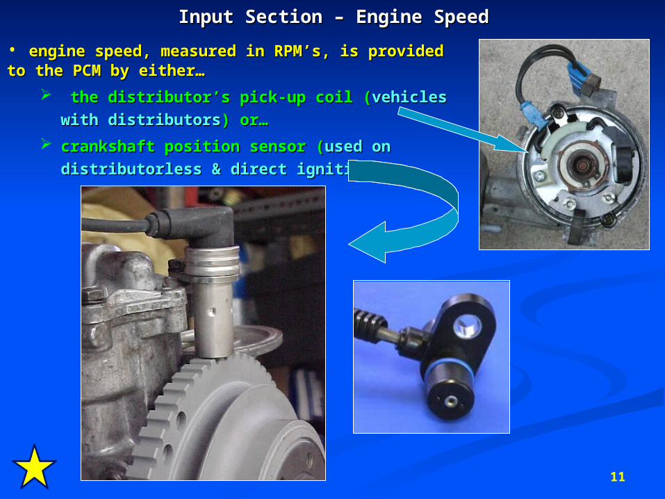
• engine speed, measured in RPM’s, is provided engine speed, measured in RPM’s, is provided to the PCM by either…to the PCM by either…
the distributor’s pick-up coil (the distributor’s pick-up coil (vehicles with vehicles with
distributorsdistributors) or… ) or…
crankshaft position sensor (crankshaft position sensor (used on used on
distributorless & direct ignitiondistributorless & direct ignition))
12
Input Section – Throttle PositionInput Section – Throttle Position
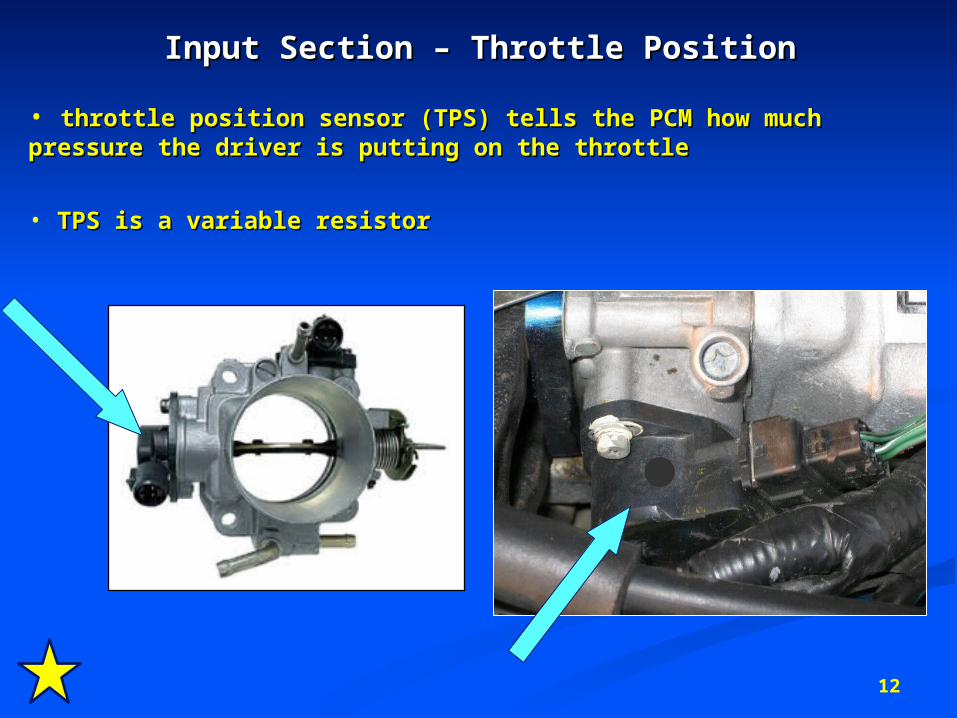
• throttle position sensor (TPS) tells the PCM how much pressure throttle position sensor (TPS) tells the PCM how much pressure the driver is putting on the throttlethe driver is putting on the throttle
• TPS is a variable resistorTPS is a variable resistor
13
Input Section – TPSInput Section – TPS
• a 5 volt signal is sent to the TPS. A return signal is sent back a 5 volt signal is sent to the TPS. A return signal is sent back
to the PCM that corresponds with throttle position.to the PCM that corresponds with throttle position.
• idle: ≈ .5 voltidle: ≈ .5 volt
• ½ throttle: ≈ 2.5 volts½ throttle: ≈ 2.5 volts
• wide open throttle ≈4.5 voltswide open throttle ≈4.5 volts
• PCM interprets these return voltages as specific throttle PCM interprets these return voltages as specific throttle
positions. positions.
• PCM can then adjust the quantity of fuel needed accordingly.PCM can then adjust the quantity of fuel needed accordingly.
14
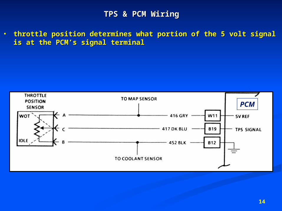
TPS & PCM WiringTPS & PCM Wiring
• throttle position determines what portion of the 5 volt signal is at throttle position determines what portion of the 5 volt signal is at the PCM’s signal terminalthe PCM’s signal terminal
PCM
15
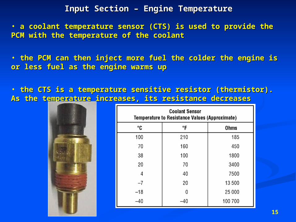
Input Section – Engine TemperatureInput Section – Engine Temperature
• a coolant temperature sensor (CTS) is used to provide the a coolant temperature sensor (CTS) is used to provide the PCM with the temperature of the coolantPCM with the temperature of the coolant
• the PCM can then inject more fuel the colder the engine is or the PCM can then inject more fuel the colder the engine is or less fuel as the engine warms up less fuel as the engine warms up
• the CTS is a temperature sensitive resistor (thermistor). As the CTS is a temperature sensitive resistor (thermistor). As the temperature increases, its resistance decreasesthe temperature increases, its resistance decreases
16
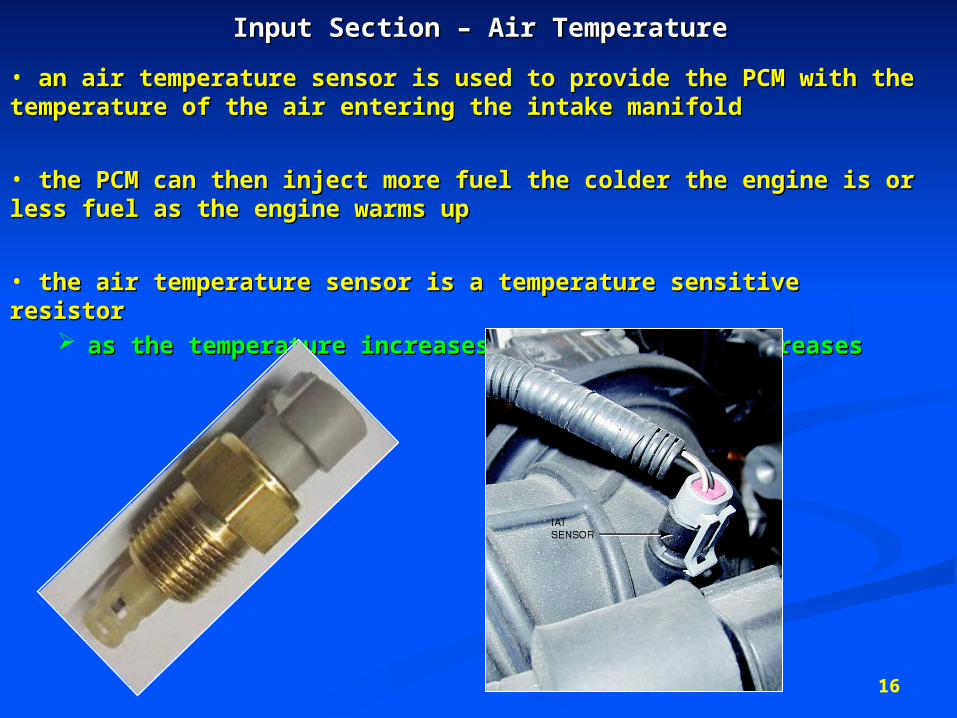
Input Section – Air TemperatureInput Section – Air Temperature
• an air temperature sensor is used to provide the PCM with the an air temperature sensor is used to provide the PCM with the temperature of the air entering the intake manifoldtemperature of the air entering the intake manifold
• the PCM can then inject more fuel the colder the engine is or less the PCM can then inject more fuel the colder the engine is or less fuel as the engine warms upfuel as the engine warms up
• the air temperature sensor is a temperature sensitive resistorthe air temperature sensor is a temperature sensitive resistor as the temperature increases, its resistance decreasesas the temperature increases, its resistance decreases
17
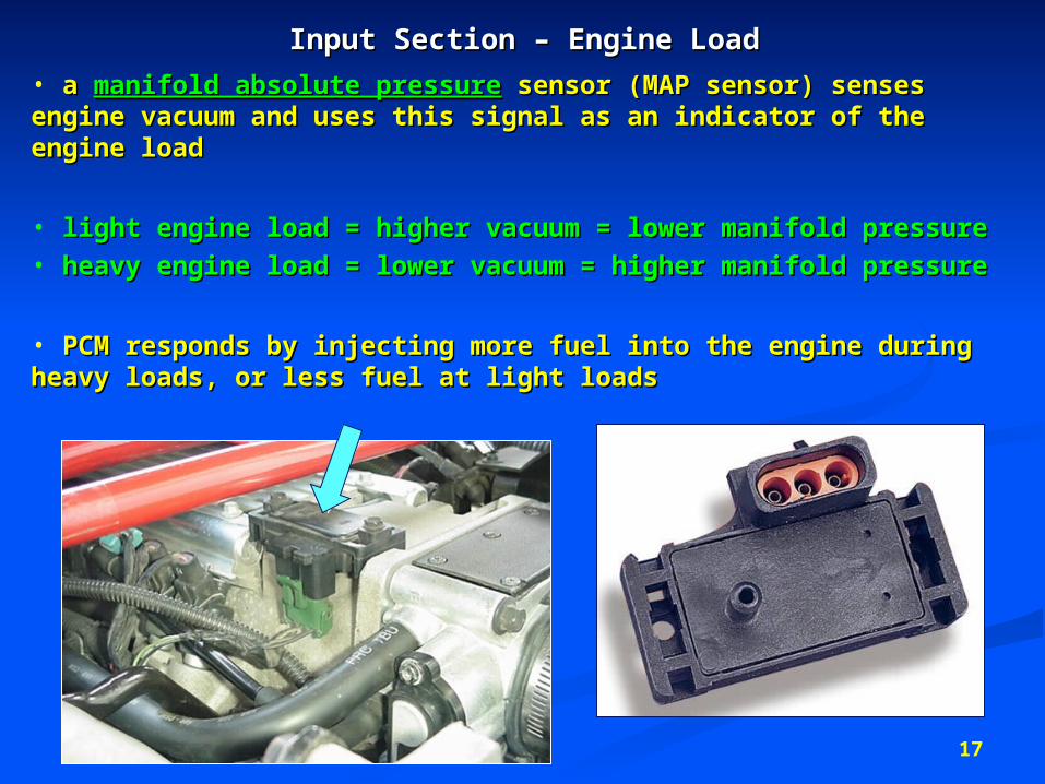
Input Section – Engine LoadInput Section – Engine Load
• a a manifold absolute pressuremanifold absolute pressure sensor (MAP sensor) senses sensor (MAP sensor) senses engine vacuum and uses this signal as an indicator of the engine vacuum and uses this signal as an indicator of the engine loadengine load
• light engine load = higher vacuum = lower manifold pressurelight engine load = higher vacuum = lower manifold pressure• heavy engine load = lower vacuum = higher manifold pressureheavy engine load = lower vacuum = higher manifold pressure
• PCM responds by injecting more fuel into the engine during PCM responds by injecting more fuel into the engine during heavy loads, or less fuel at light loadsheavy loads, or less fuel at light loads
18
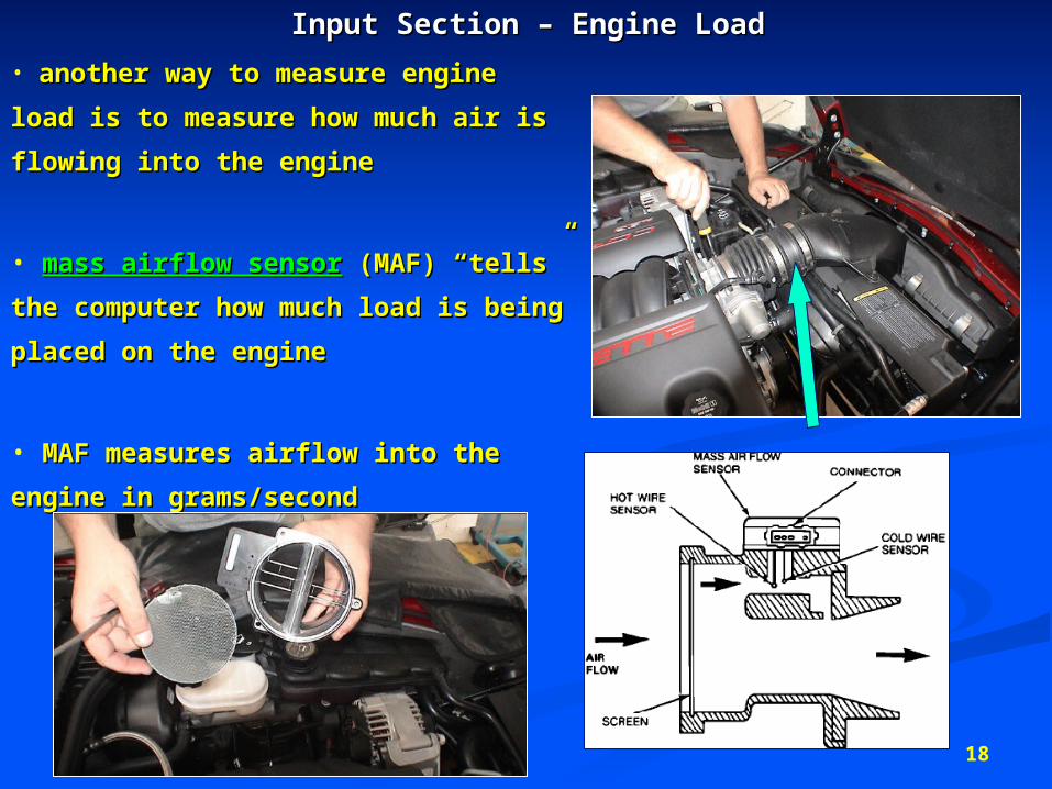
Input Section – Engine LoadInput Section – Engine Load
• another way to measure engine another way to measure engine
load is to measure how much air is load is to measure how much air is
flowing into the engineflowing into the engine
• mass airflow sensormass airflow sensor (MAF) “tells” (MAF) “tells”
the computer how much load is being the computer how much load is being
placed on the engineplaced on the engine
• MAF measures airflow into the MAF measures airflow into the
engine in grams/secondengine in grams/second
19
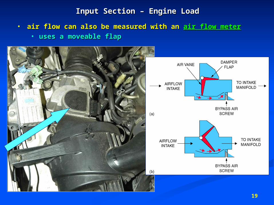
Input Section – Engine LoadInput Section – Engine Load
• air flow can also be measured with an air flow can also be measured with an air flow meterair flow meter• uses a moveable flapuses a moveable flap
20
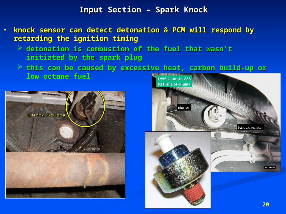
Input Section – Spark KnockInput Section – Spark Knock
• knock sensor can detect detonation & PCM will respond by knock sensor can detect detonation & PCM will respond by retarding the ignition timingretarding the ignition timing detonation is combustion of the fuel that wasn’t initiated detonation is combustion of the fuel that wasn’t initiated
by the spark plugby the spark plug this can be caused by excessive heat, carbon build-up or this can be caused by excessive heat, carbon build-up or
low octane fuellow octane fuel
21
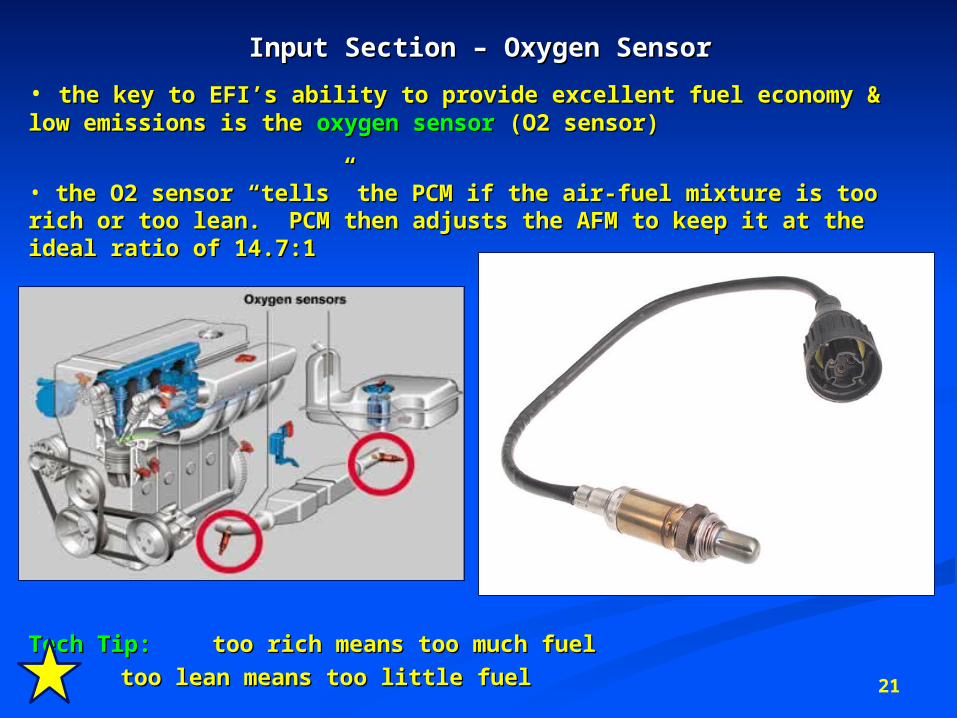
Input Section – Oxygen SensorInput Section – Oxygen Sensor
• the key to EFI’s ability to provide excellent fuel economy & low the key to EFI’s ability to provide excellent fuel economy & low emissions is the emissions is the oxygen sensoroxygen sensor (O2 sensor) (O2 sensor)
• the O2 sensor “tells” the PCM if the air-fuel mixture is too rich the O2 sensor “tells” the PCM if the air-fuel mixture is too rich or too lean. PCM then adjusts the AFM to keep it at the ideal or too lean. PCM then adjusts the AFM to keep it at the ideal ratio of 14.7:1ratio of 14.7:1
Tech Tip:Tech Tip: too rich means too much fueltoo rich means too much fuel
too lean means too little fuel too lean means too little fuel
22
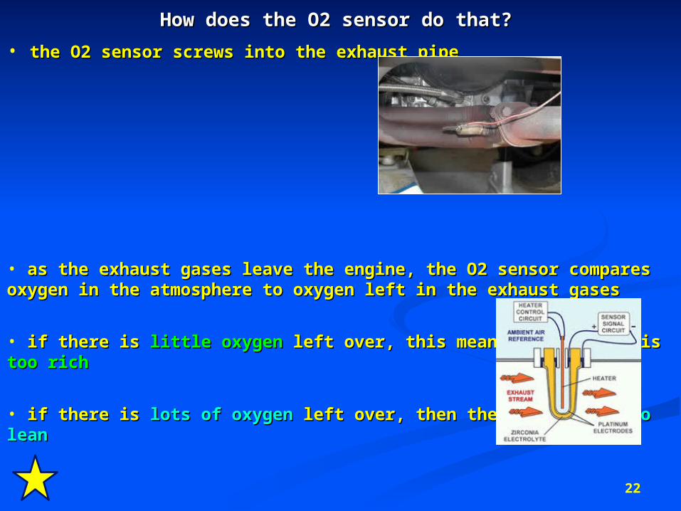
How does the O2 sensor do that?How does the O2 sensor do that?
• the O2 sensor screws into the exhaust pipe the O2 sensor screws into the exhaust pipe
• as the exhaust gases leave the engine, the O2 sensor compares oxygen in the atmosphere to as the exhaust gases leave the engine, the O2 sensor compares oxygen in the atmosphere to oxygen left in the exhaust gasesoxygen left in the exhaust gases
• if there is if there is little oxygenlittle oxygen left over, this means the mixture is left over, this means the mixture is too richtoo rich
• if there is if there is lots of oxygenlots of oxygen left over, then the mixture is left over, then the mixture is too lean too lean
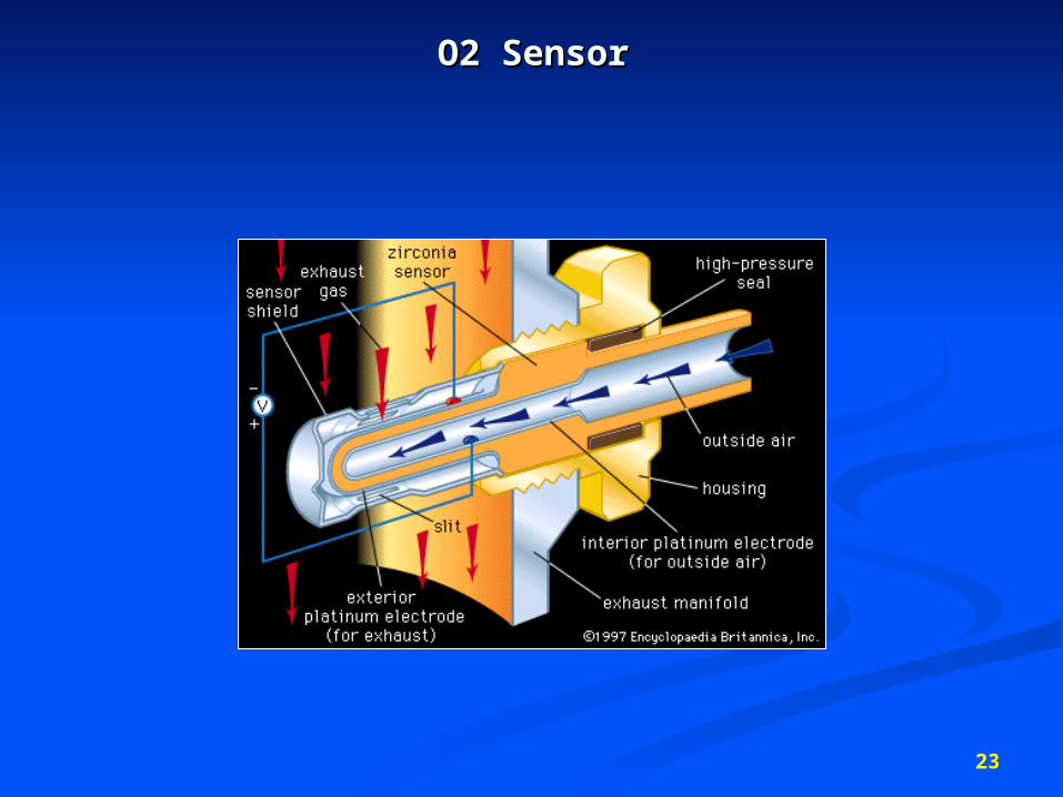
O2 SensorO2 Sensor
23
24
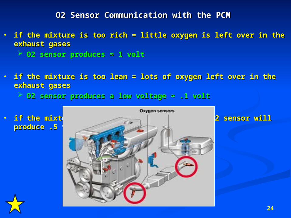
O2 Sensor Communication with the PCMO2 Sensor Communication with the PCM
• if the mixture is too rich = little oxygen is left over in the exhaust gasesif the mixture is too rich = little oxygen is left over in the exhaust gases O2 sensor produces ≈ 1 voltO2 sensor produces ≈ 1 volt
• if the mixture is too lean = lots of oxygen left over in the exhaust gasesif the mixture is too lean = lots of oxygen left over in the exhaust gases O2 sensor produces a low voltage ≈ .1 voltO2 sensor produces a low voltage ≈ .1 volt
• if the mixture is perfect (14.7:1), then the O2 sensor will produce .5 voltif the mixture is perfect (14.7:1), then the O2 sensor will produce .5 volt
25
Output SectionOutput Section
26
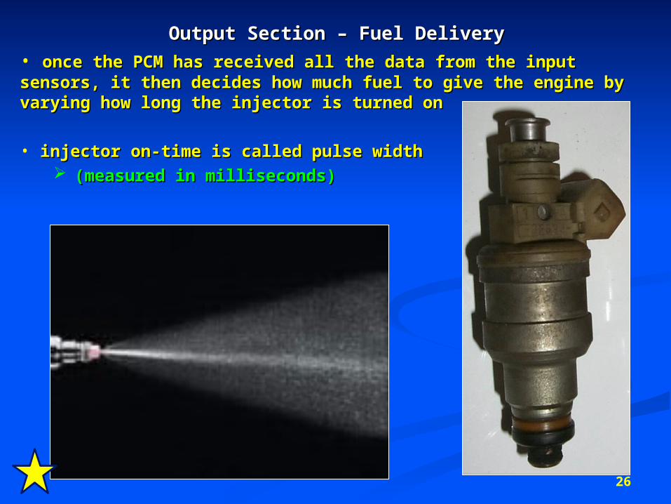
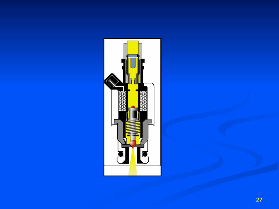
Output Section – Fuel DeliveryOutput Section – Fuel Delivery• once the PCM has received all the data from the input sensors, it once the PCM has received all the data from the input sensors, it then decides how much fuel to give the engine by varying how long then decides how much fuel to give the engine by varying how long the injector is turned onthe injector is turned on
• injector on-time is called pulse width injector on-time is called pulse width (measured in milliseconds)(measured in milliseconds)
27
28
29
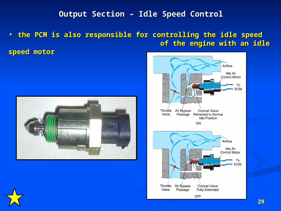
Output Section – Idle Speed ControlOutput Section – Idle Speed Control
• the PCM is also responsible for controlling the idle speed the PCM is also responsible for controlling the idle speed of the engine with an idle speed motor of the engine with an idle speed motor
30
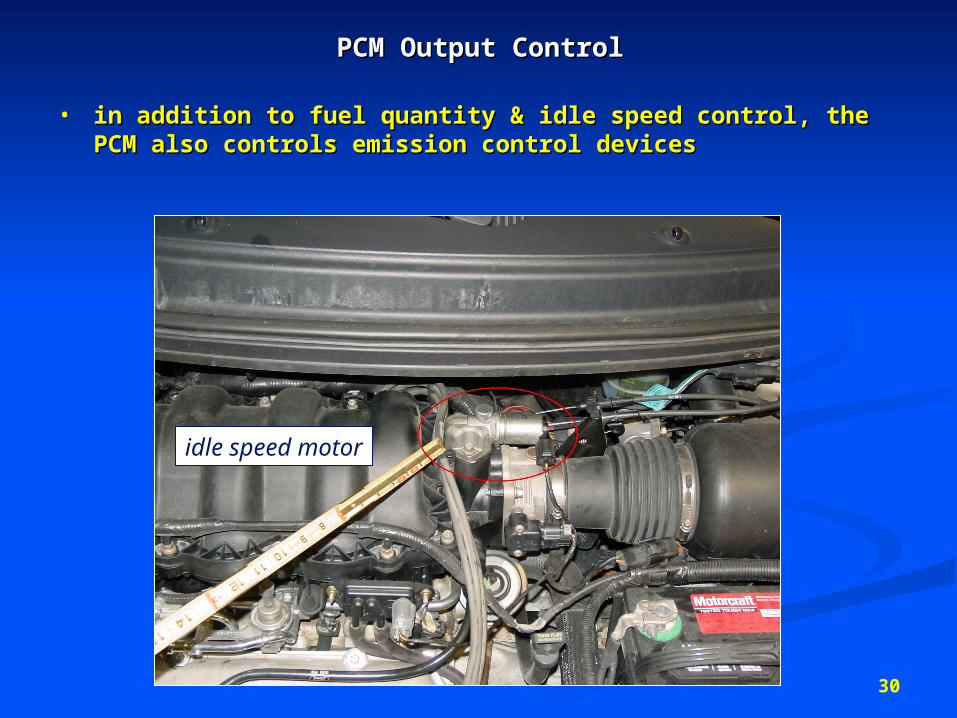
PCM Output ControlPCM Output Control
• in addition to fuel quantity & idle speed control, the PCM in addition to fuel quantity & idle speed control, the PCM also controls emission control devicesalso controls emission control devices
idle speed motor
31
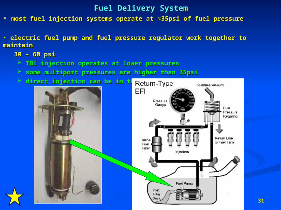
Fuel Delivery SystemFuel Delivery System• most fuel injection systems operate at ≈35psi of fuel pressure most fuel injection systems operate at ≈35psi of fuel pressure
• electric fuel pump and fuel pressure regulator work together to maintain electric fuel pump and fuel pressure regulator work together to maintain
30 – 60 psi 30 – 60 psi TBI injection operates at lower pressuresTBI injection operates at lower pressures some multiport pressures are higher than 35psisome multiport pressures are higher than 35psi direct injection can be in the 400 – 1500psi rangedirect injection can be in the 400 – 1500psi range
33
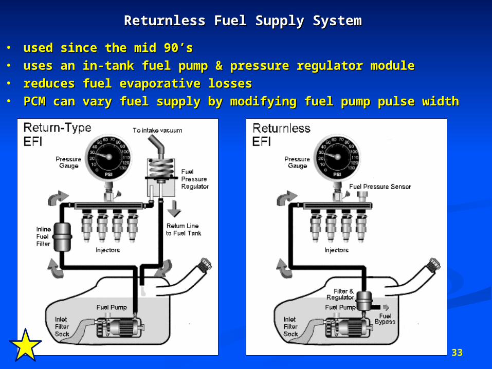
Returnless Fuel Supply System Returnless Fuel Supply System
• used since the mid 90’sused since the mid 90’s• uses an in-tank fuel pump & pressure regulator moduleuses an in-tank fuel pump & pressure regulator module• reduces fuel evaporative lossesreduces fuel evaporative losses• PCM can vary fuel supply by modifying fuel pump pulse widthPCM can vary fuel supply by modifying fuel pump pulse width
34
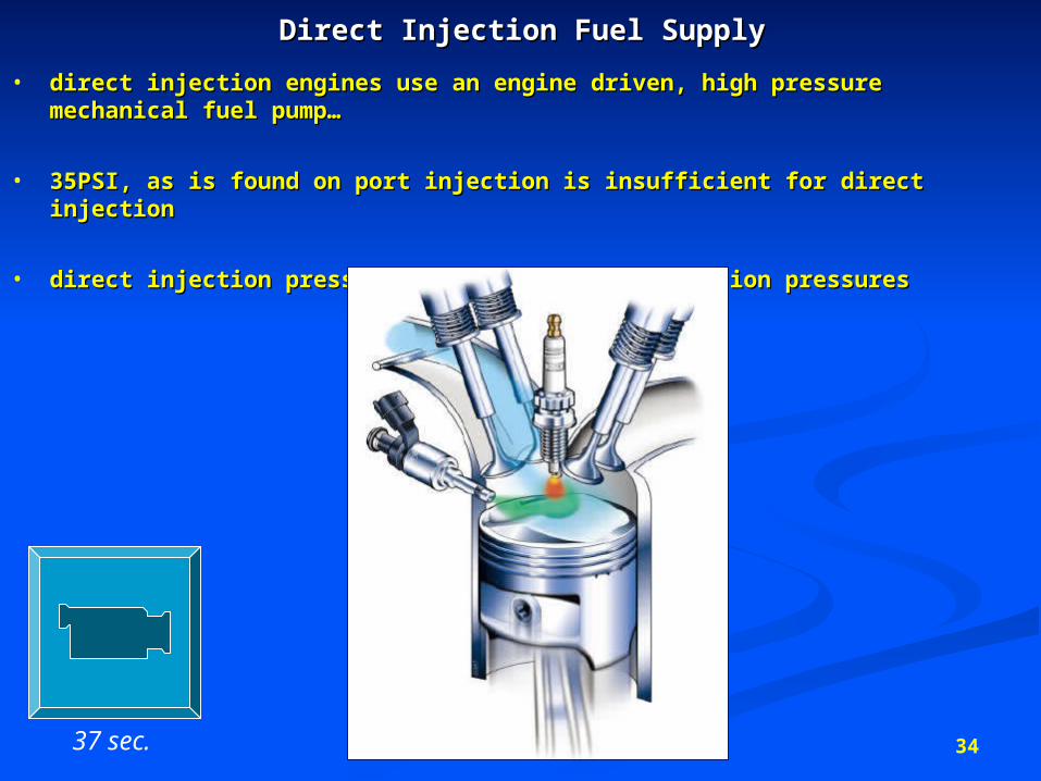
Direct Injection Fuel SupplyDirect Injection Fuel Supply
• direct injection engines use an engine driven, high pressure direct injection engines use an engine driven, high pressure mechanical fuel pump…mechanical fuel pump…
• 35PSI, as is found on port injection is insufficient for direct injection35PSI, as is found on port injection is insufficient for direct injection
• direct injection pressures must overcome compression pressuresdirect injection pressures must overcome compression pressures
37 sec.
35
Gasoline Fuel InjectionGasoline Fuel Injection
• optimal way of delivering fuel to a spark ignition engine when optimal way of delivering fuel to a spark ignition engine when compared to carburetorscompared to carburetors
more exact control of fuel deliverymore exact control of fuel delivery
AFM ratio better matched to the engine working conditionsAFM ratio better matched to the engine working conditions
better fuel economybetter fuel economy
fewer emissionsfewer emissions
less cylinder wear (less chance of fuel washing oil off cylinder)less cylinder wear (less chance of fuel washing oil off cylinder)
better performance (driveability) better performance (driveability)
36
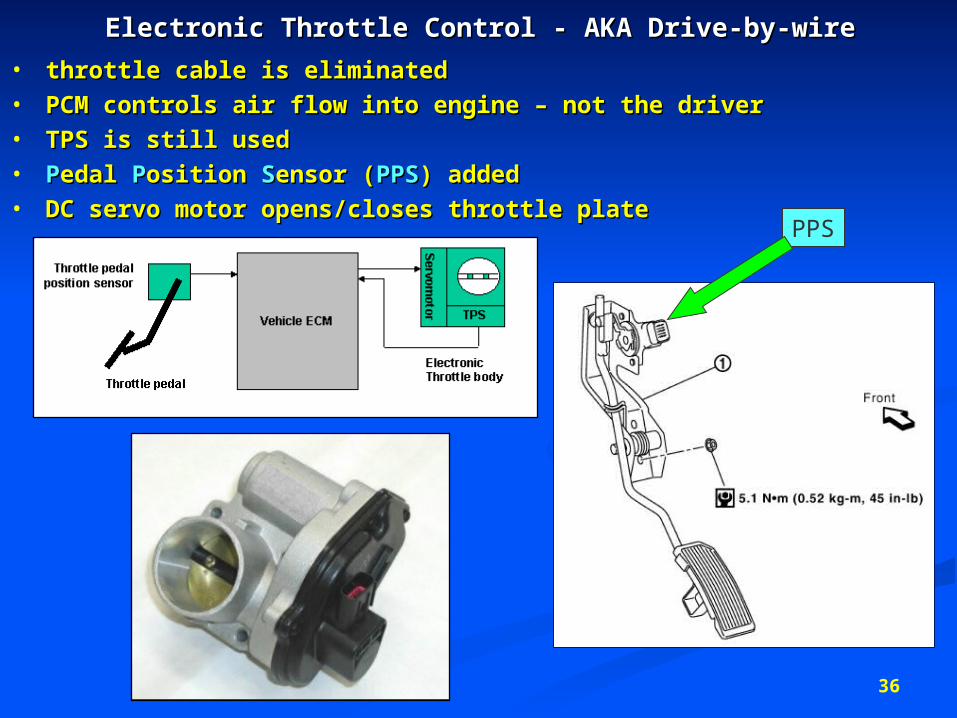
Electronic Throttle Control - AKA Drive-by-wireElectronic Throttle Control - AKA Drive-by-wire
• throttle cable is eliminatedthrottle cable is eliminated• PCM controls air flow into engine – not the driverPCM controls air flow into engine – not the driver• TPS is still usedTPS is still used• PPedal edal PPosition osition SSensor (ensor (PPSPPS) added) added• DC servo motor opens/closes throttle plateDC servo motor opens/closes throttle plate
PPS