1 elements of a digital communication system block diagram of a communication system:
Post on 21-Dec-2015
224 views
TRANSCRIPT

1
Elements of a Digital Communication System
• Block diagram of a communication system:
Information source and
input transducer
Channel decoder
Output transducer
Channel
Digital modulator
Channel encoder
Source encoder
Source decoder
Digital demodulator

2
Mathematical Models for Communication Channels
• Additive Noise Channel:– In presence of attenuation:
+
S(t)
r(t) = s(t) + n(t)
n(t)
channel
)()()()( tntsttr
3
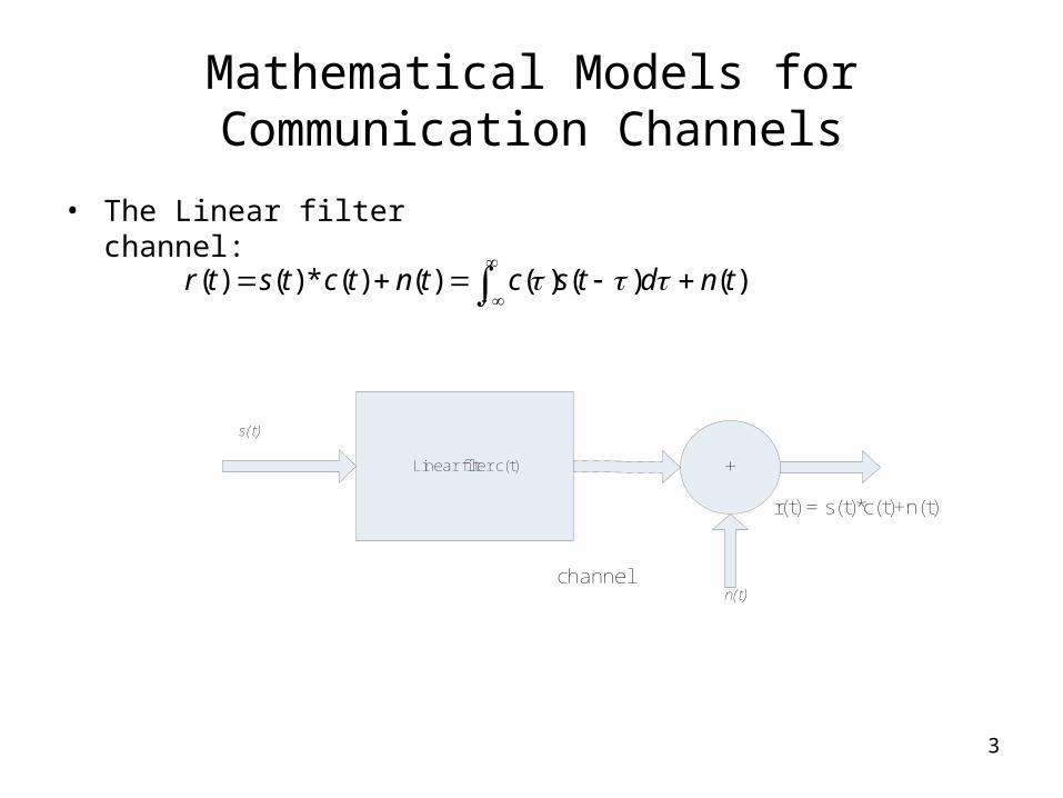
Mathematical Models for Communication Channels
• The Linear filter channel:
)()()()()(*)()( tndtsctntctstr
Linear filter c(t) +
channel
s(t)
n(t)
r(t) = s(t)*c(t)+n(t)

4
Mathematical Models for Communication Channels
• Linear Time-Variant Filter Channel:– Are charachterized by a time-variant channel impulse response
);( tc
Linear time_variant filter +
channel
s(t)
n(t)
r(t)

5
Representation of Band-Pass Signals and Systems
• Representation of Band-Pass Signals:
Energy of the signal:
• Representation of Linear Band-Pass Systems:
• Response of a Band-Pass System to a Band-Pass Signal:
)2sin()()2cos()()( tftytftxts cc
dttsl2)(
2
1
tfjl
tfjl
cc ethethth 22 )()()(
tfjl
cetrtr 2)(Re)(

6
Orthogonal Expansion of Signals
• We can express M orthonormal signals as a Linear combination of basis functions and hence can be defined as
• Linear digitally modulated signals can be expanded in terms of two orthonormal basis functions given by:
and
)(tsn )(tf n
Mktfsts n
N
nknk ,..,2,1),()(
1
tfT
tf c2cos2
)(1 tfT
tf c2sin2
)(2

7
Representation of Digitally Modulated Signals
• Pulse-amplitude-modulated Signals (PAM):
• Phase-modulated signals (PSK):
• Quadrature amplitude modulation (QAM):
tfjmm
cetgAts 2)(Re)( m=1,2,…M
tfmM
tgtfmM
tgts ccm 2sin)1(2
sin)(2cos)1(2
cos)()(
tfjmsmcm
cetgjAAts 2)()(Re)( m=1,2,..,M,
tftgAtftgA cmscmc 2sin)(2cos)(

8
Representation of Digitally Modulated Signals
• Orthogonal multidimensional signals:
• Biorthogonal signals:• Simplex signals:• m=1, 2,…, M..
• Signal waveforms from binary codes:
cTt 0
mNmmm cccC ...21
,' sss mm
mNmm ccC ....1
tf
TtSc c
c
cmjmj 2cos
2)(1
tf
TtSc c
c
cmjmj 2cos
2)(0 cTt 0

9
Optimum Receivers Corrupted by additive White Gaussian Noise- I
• General Receiver:
Receiver is subdivided into:– 1. Demodulator.
• (a) Correlation Demodulator.
• (b) Matched Filter Demodulator.
– 2. Detector.
+
Sm(t)
r(t) = sm(t) + n(t)
n(t)
channel
)0(),()()( Tttntstr m
10
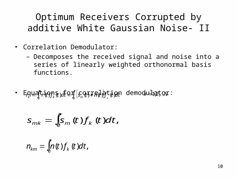
Optimum Receivers Corrupted by additive White Gaussian Noise- II
• Correlation Demodulator:– Decomposes the received signal and noise into a series of
linearly weighted orthonormal basis functions.
• Equations for correlation demodulator:
dttftntsdttftrrk
T T
mkk )()()()()(0 0 Nk ,...2,1
,)()(0
dttftss k
T
mmk
,)()(0
dttftnn k
T
km

11
Optimum Receivers Corrupted by additive White Gaussian Noise- III
• Matched Filter Demodulator:– Equation of a matched filter:
• Output of the matched filter is given by:
k=1,2, …N
),()( tTfth kk Tt 0
dthtrty k
T
k )()()(0
dtTftr k
T)()(
0

12
Optimum Receivers Corrupted by additive White Gaussian Noise- IV
• Optimum Detector:– The optimum detector should make a decision on the
transmitted signal in each signal interval based on the observed vector.
• Optimum detector is defined by:
m=1,2,… M
or
N
nmnmn
N
nn
N
nnm ssrrsrD
1
2
11
2 2),(
,222
mm ssrr
),( msrD2
2 mm ssr

13
OFDM
• It is a block modulation scheme where data symbols are transmitted in parallel by employing a large number of orthogonal sub-carriers.
• Equation of complex envelope of the OFDM signal:
• where
n
nxnTtbAts ),()(
1
0
)21
(2exp)(),(
N
knan T
tN
kjxthxtb
k

14
General FFT based OFDM system-I
• Block diagram of FFT based OFDM transmitter :
• Equations at the transmmitter end:
)(2
exp)(1
0
tuNT
ktjxAts r
s
N
kk
,2
exp)(1
0
s
N
kksn N
knjxAnTsX
X0
XN-1XN-2...X1X0
IFFT
XN-1XN-2...X1
Insert Cyclic prefix
D/A
D/A
nX gnX
gInX
gQnX
)(~ tsl
)(~ tsQ
kX

15
General FFT based OFDM system-II
• Block diagram of FFT based OFDM receiver:
• At the demodulator:
1
0
21 N
n
N
nij
ni eRN
Z
R0
ZN-1ZN-2...Z1Z0
FFT
RN-1RN-2...R1
Serial metric computer
nZ
)( mv
Remove cyclic prefixA/D
A/D)(~ trl
)(~ trQ
nkR ,
QnR
L
m
N
mij
mi eg0
2
iii AxZ

16
General FFT based OFDM system-II
• Merits of OFDM:
– 1. the modulation and the demodulation can be achieved in the frequency-domain by using a DFT.
– 2. the effects of ISI can be eliminated with the introduction of the guard interval.

17
IMPLEMENTATION OF OFDM SYSTEM-I
• Basic implementation of OFDM system:
iii AxZ
1
0
21 N
n
N
nij
ni eRN
Z
L
m
N
mij
mi eg0
2
Serial To Parallel
Converter
BPSK
Detector
BPSK
BPSK
+
+
+
Bits
0
1
127
R0
R127
R1
.
.
.
.
.
.
.
.
.
.
.
.
.
.
.
.
.
.
.
.
.
.
.
.
.
.
.
.
.
.
X0
X1
X127
n0
n1
n127

18
SIMULATION RESULTS.
• Perfomance charachteristics were obtained for the simulated OFDM system.
10 15 20 25 30 35 40 45 5010
-6
10-5
10-4
10-3
10-2
10-1
Non Fading ChannelFading Channel

19
Conclusion.
• 1. OFDM communication system exhibits better Pe Vs SNR curves in case of Non-Fading channel as compared to the Fading channel.
• 2. As the value of the SNR is increased the value of Pe gradually decreases.
• 3. Perfomance charachteristics of simulated OFDM communication system are consistent with the performance charachteristics of the general OFDM communication system.