1 emergency relief gary van sciver september 16, 2008 ·
TRANSCRIPT

1
Emergency Relief
Gary Van Sciver
September 16, 2008
2
Gary Van Sciver
Process Engineer – 8 years
Risk Analyst – 22 years
ETC – 2 ½ years

3
Presentation Overview
ERS
Normal Vent
1
23
4
5
1. Normal vent2. Design basis3. Mechanical4. Discharge
5. MOC

4
Terminology (ERS)
Emergency
Relief
System

5
1. Normal Vent
ERS
Normal Vent
1
23
4
5
1. Normal vent2. Design basis3. Mechanical4. Discharge
5. MOC

6
What is the difference between the normal vent & the
emergency vent?EmergencyVent
Normal Vent

7
What are the differences? (between the normal & emergency vents)
• No blocking devices in ERS• No flame arresters in ERS• ERS usually bigger• Normal vent also handles vacuum• Pollution abatement for normal vent• Normal vent opens first• Manifolding for normal vent .

8
VPRV (conservation vent)

9
VPRV(vacuum pressure relief valve)
To/fromvessel
Fromatmosphere
Discharge

10
ManifoldsOne pollution abatement device will normally
handle the discharge of multiple vessels
PollutionAbatement
Device

11
VPRV(vacuum pressure relief valve)
To/fromvessel
Fromatmosphere
Discharge

12
Storage Tank Under Vacuum
13
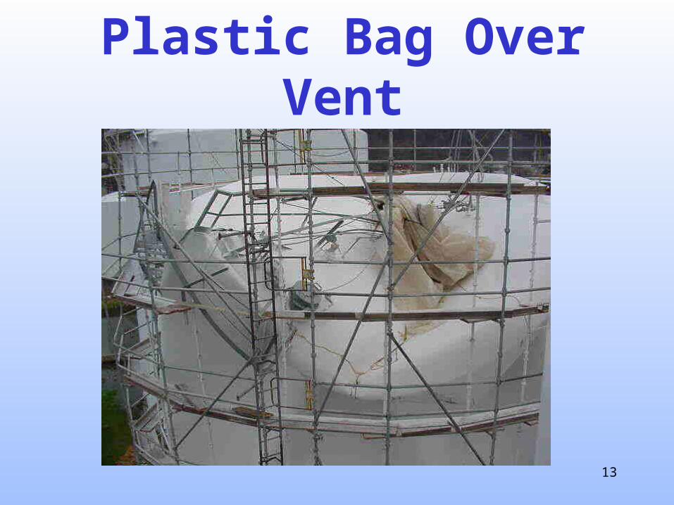
Plastic Bag Over Vent

14
2. Design Basis
ERS
Normal Vent
1
23
4
5
1. Normal vent2. Design basis3. Mechanical4. Discharge
5. MOC

15
Upset Scenario...
Series of events leading to high vessel pressure

16
What do we want the ERS to protect against?...
17
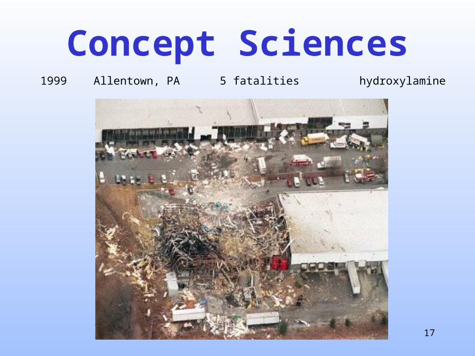
Concept Sciences1999 Allentown, PA 5 fatalities hydroxylamine
18
Concept Sciences
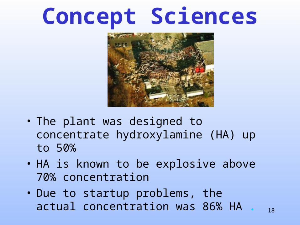
• The plant was designed to concentrate hydroxylamine (HA) up to 50%
• HA is known to be explosive above 70% concentration
• Due to startup problems, the actual concentration was 86% HA .

19
Concept Sciences

20
Flammable Discharge
21
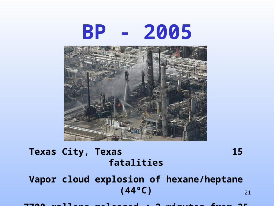
BP - 2005
Texas City, Texas 15 fatalities
Vapor cloud explosion of hexane/heptane (44ºC)
7700 gallons released < 2 minutes from 35 m height
22
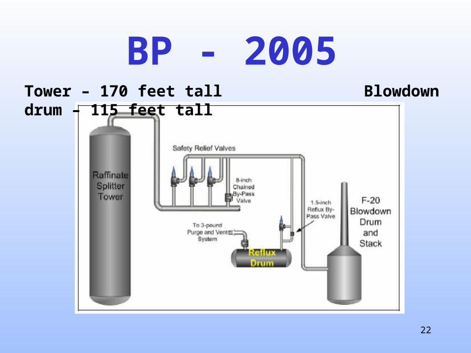
BP - 2005Tower – 170 feet tall Blowdown drum – 115 feet tall

23
BP - 2005
Truck parked, but idling about
25 feet from blowdown drum
Eyewitness saw engine over-revving and
backfiring sparks

24
BP - 2005
25
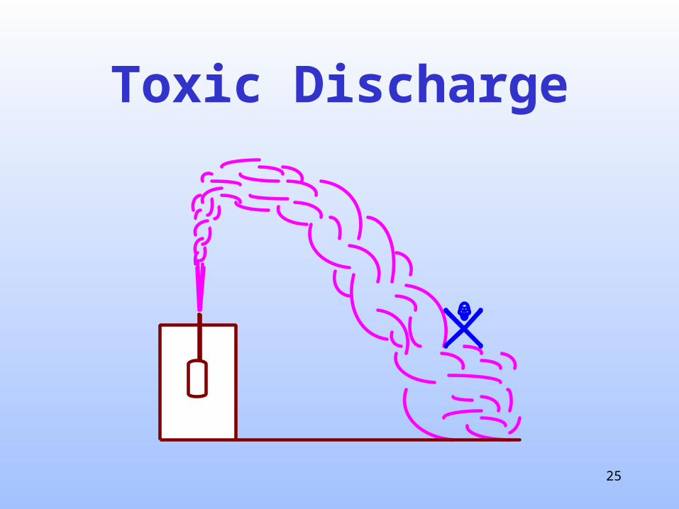
Toxic Discharge
26
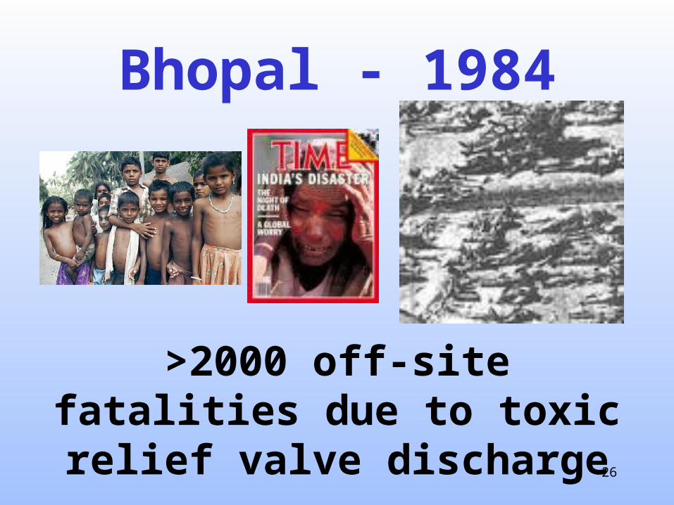
Bhopal - 1984
>2000 off-site fatalities due to toxic relief valve discharge

27
Bhopal
Taloja
Delhi
Kolkata(formerlyCalcutta)
Chennai(formerlyMadras)
Mumbai(formerlyBombay)
Bhopal
IndiaNH 12
NH 12
Upper Lake
NH 86NH 86
UnionCarbide
Toxic GasCloud
Highly-Populated Region of Bhopal
28
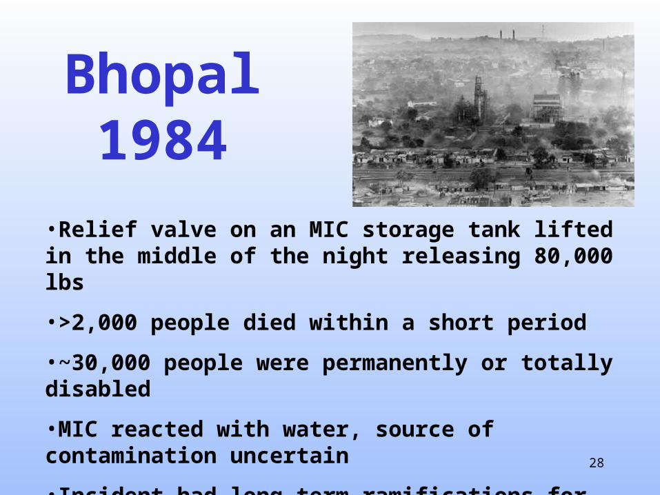
Bhopal1984
•Relief valve on an MIC storage tank lifted in the middle of the night releasing 80,000 lbs
•>2,000 people died within a short period
•~30,000 people were permanently or totally disabled
•MIC reacted with water, source of contamination uncertain
•Incident had long-term ramifications for Union Carbide and the chemical industry as a whole .

29
Bhopal - 1984
MICStorage
Refrigeration Scrubber Flare

30
Design Basis Procedure
1. Identification 2. Sizing 3. Selection

31
How do we identify upsets?

32
2 important upsets

33
Fire ExposureRD

34
Runaway reactionHigh
temperatureor unusual
composition

35
Some other non-reactive upsets

36
Excessive heating(steam valve failures, coil leaks)
Steam wide open
RD
37
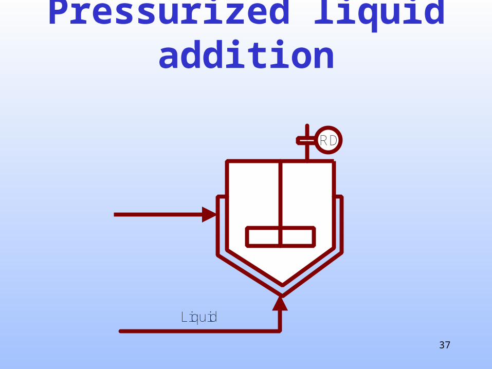
Pressurized liquid addition
Liquid
RD

38
Pressurized gas addition(line blowing, pressure transfers, pads or purges)
RD
Air, Nitrogen or Steam

39
Some reactive upsets

40
Inadequate cooling
Coolingwaterfails

41
Inadequate heat sinkWater NOT
charged

42
Excessive reactant
Reactant
Bypass open

43
Poor reactivityAgitator off
Reactant

44
Design Basis Procedure
1. Identification
2. Sizing

45
Sizing vents is straightforward but we do need kinetics
data for reactive scenarios

46
Types of runaway reaction
• Vapor Pressure
• Gas Generating .
47
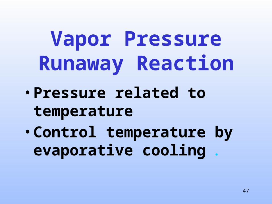
Vapor PressureRunaway Reaction
• Pressure related to temperature• Control temperature by
evaporative cooling .

48
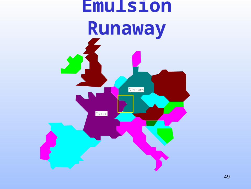
Emulsion Runaway
• 1995, one-shot emulsion process• Water charging system failed• New operator being trained, batch not stopped• 2,000-gallon, 120-psig reactor • Broke 35-psig, 18-inch rupture disk
• ~1200 lbs ethyl acrylate released.
35% EA 70% EA
Normal Upset
90C max 190C max
49
Emulsion Runaway
France
Germany
50
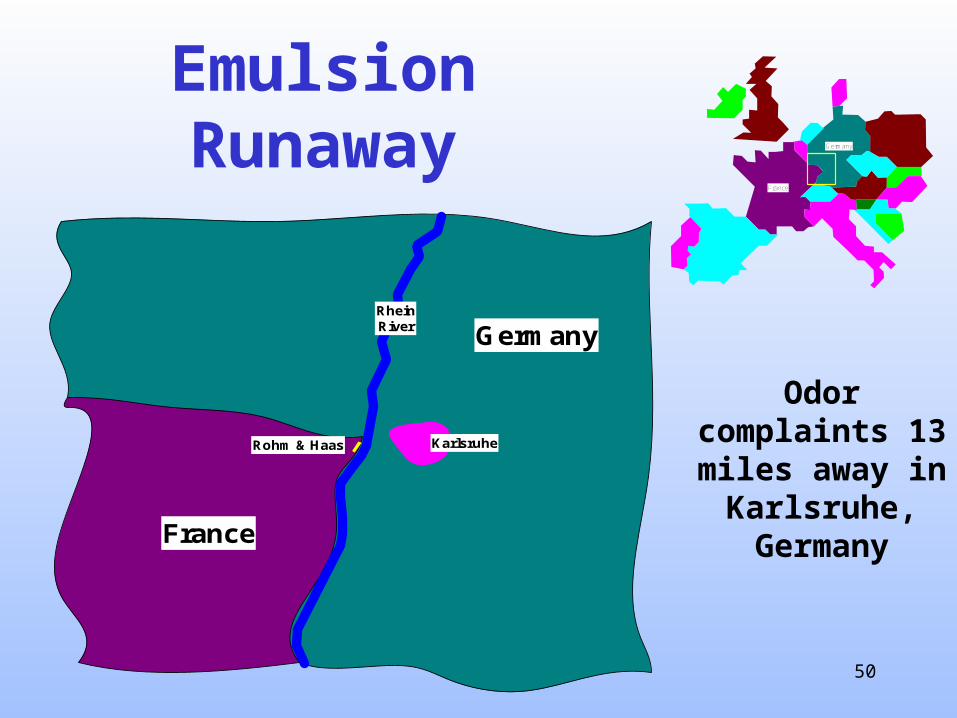
Emulsion Runaway
France
Germany
Rohm & Haas Karlsruhe
RheinRiver
Odor complaints 13 miles away in
Karlsruhe, Germany
France
Germany
51
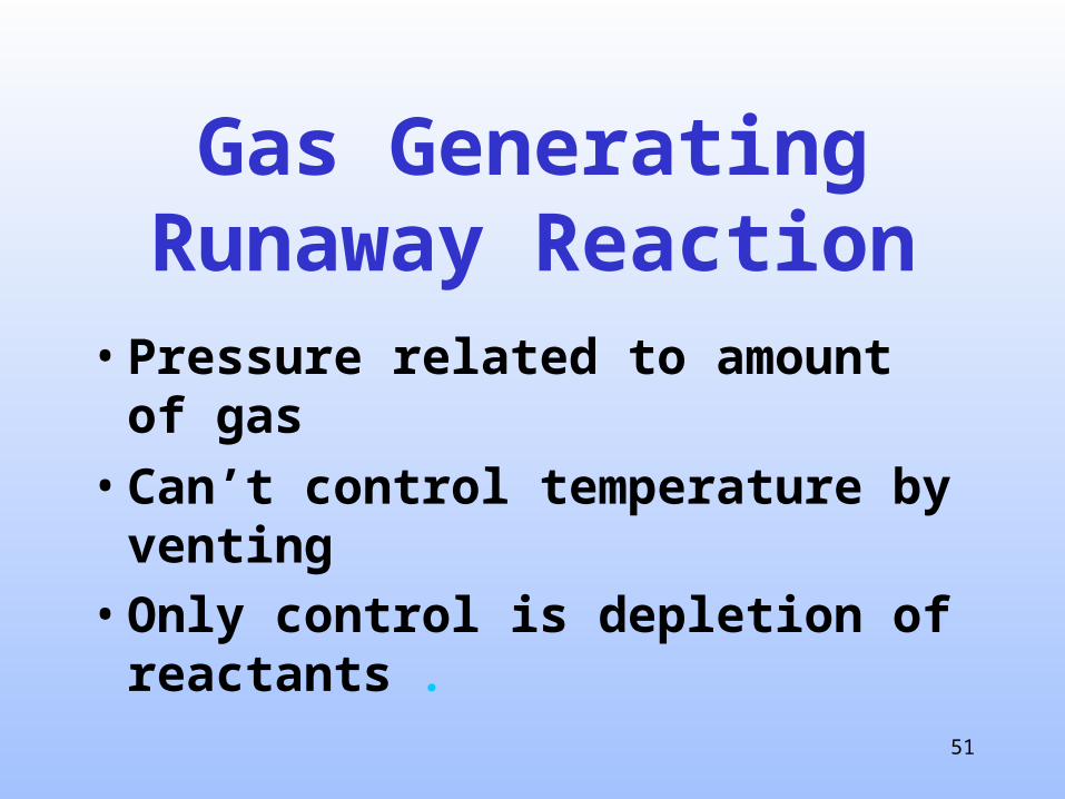
Gas GeneratingRunaway Reaction
• Pressure related to amount of gas
• Can’t control temperature by venting
• Only control is depletion of reactants .
52
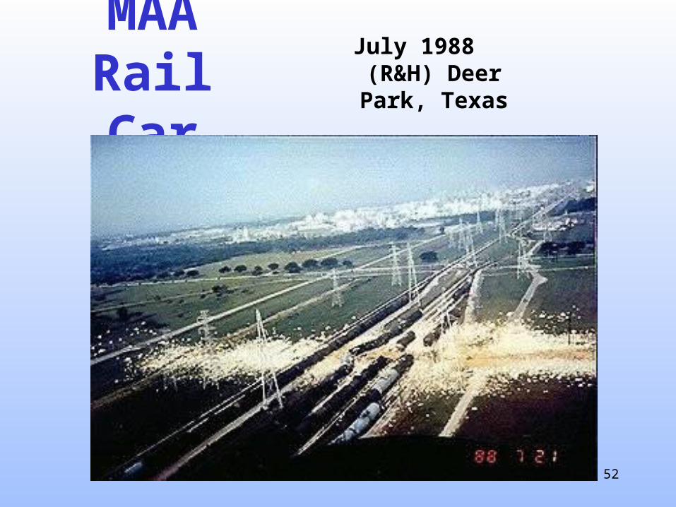
MAA Rail Car
July 1988 (R&H) Deer Park, Texas

53
VSP(Vent Sizing Package)

54
VSP
120 cctest cell
PFill
T
RDPC
X
X
X
X
X
X
X
X
X
X
X
X
X
X
X X X X X X
55
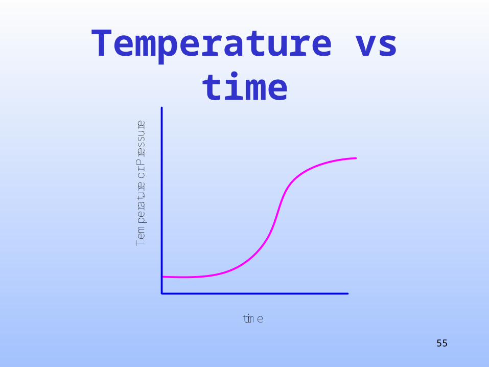
Temperature vs time
time
Tem
pera
ture
or
Pre
ssur
e
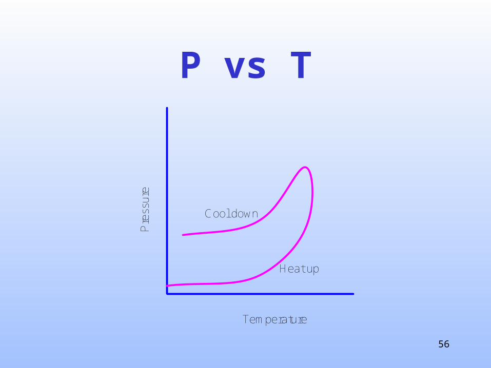
56
P vs T
Temperature
Pre
ssur
e
Heat up
Cool down

57
Design Basis Procedure
1. Identification 2. Sizing 3. Selection

58
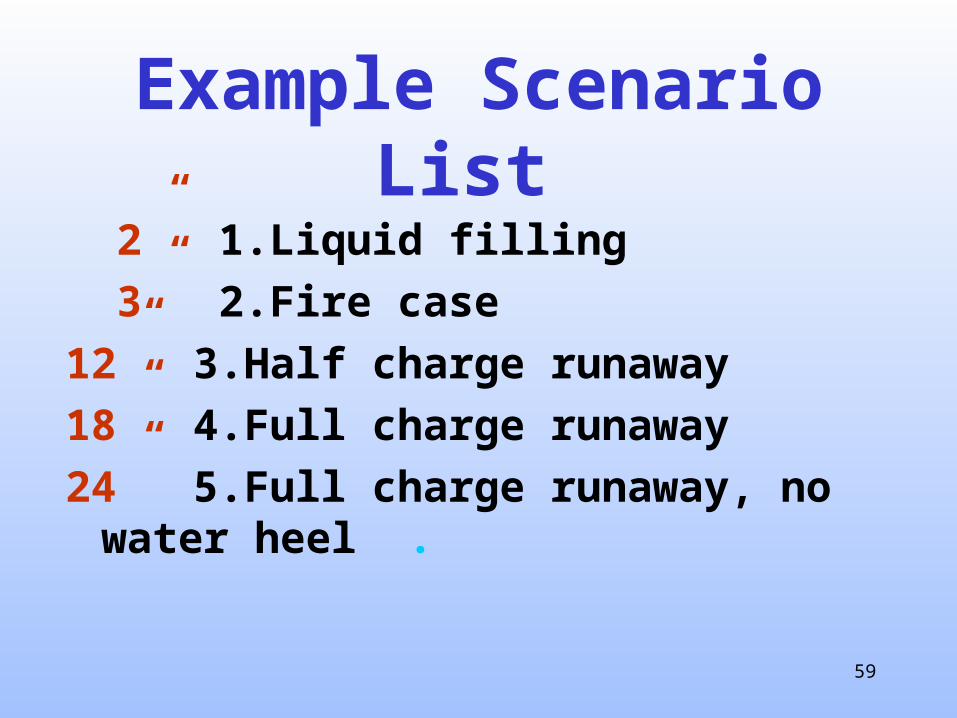
List the scenarios in
order of increasing relief
device size requirement
59
Example Scenario List
2” 1.Liquid filling 3” 2.Fire case12” 3.Half charge runaway18” 4.Full charge runaway24” 5.Full charge runaway, no
water heel .

60
Selection Approaches
1. Codes
2. Tradition3. Risk .

61
NFPA 30 requires ERS protection against fire for
aboveground storage tanks of flammables &
combustibles
Codes

62
Fire Case Requirement
Fire Case Heat Input
1.0E+05
1.0E+06
1.0E+07
1.0E+08
10 100 1,000 10,000
Area (sq feet)
Q (
Btu
/ho
ur)
<1 psig
>1 psig

63
Tradition

64
Take advantage of our previous experience

65
For example: batch reactor ERS sized for a full-charge
runaway

66
Risk
67
Risk Management Services(RMS)
68
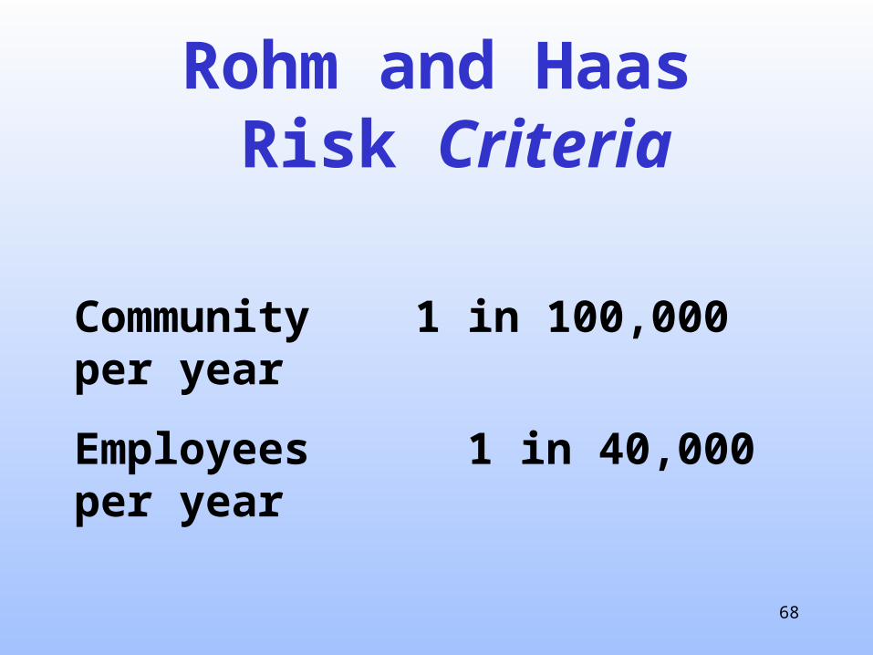
Rohm and Haas Risk Criteria
Community 1 in 100,000 per year
Employees 1 in 40,000 per year

69
3. Mechanical
ERS
Normal Vent
1
23
4
5
1. Normal vent2. Design basis3. Mechanical4. Discharge
5. MOC

70
Vessel Failure
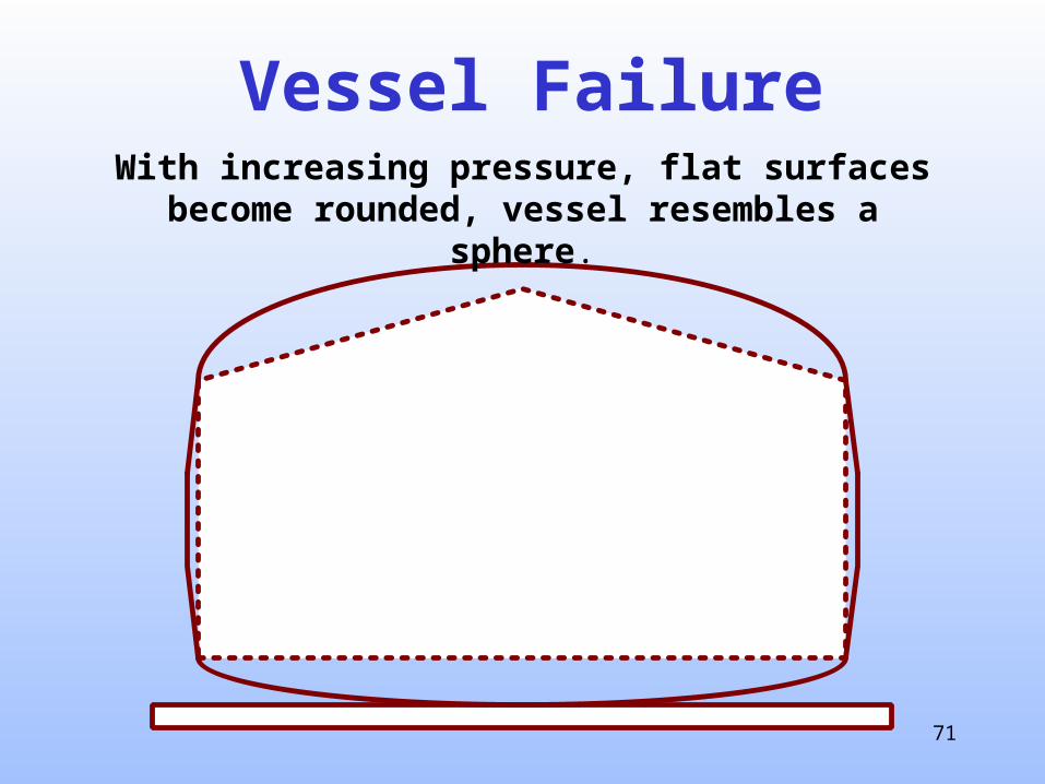
71
Vessel FailureWith increasing pressure, flat surfaces become rounded,
vessel resembles a sphere.
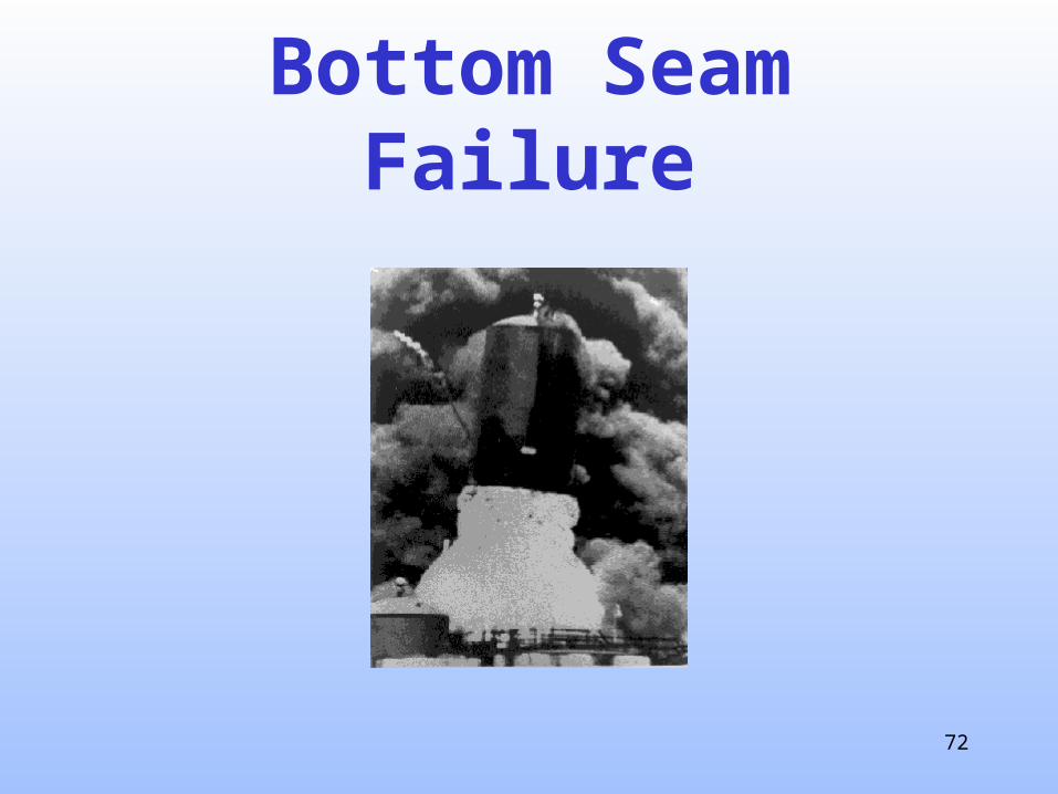
72
Bottom Seam Failure

73
Hold Down Lug - Older
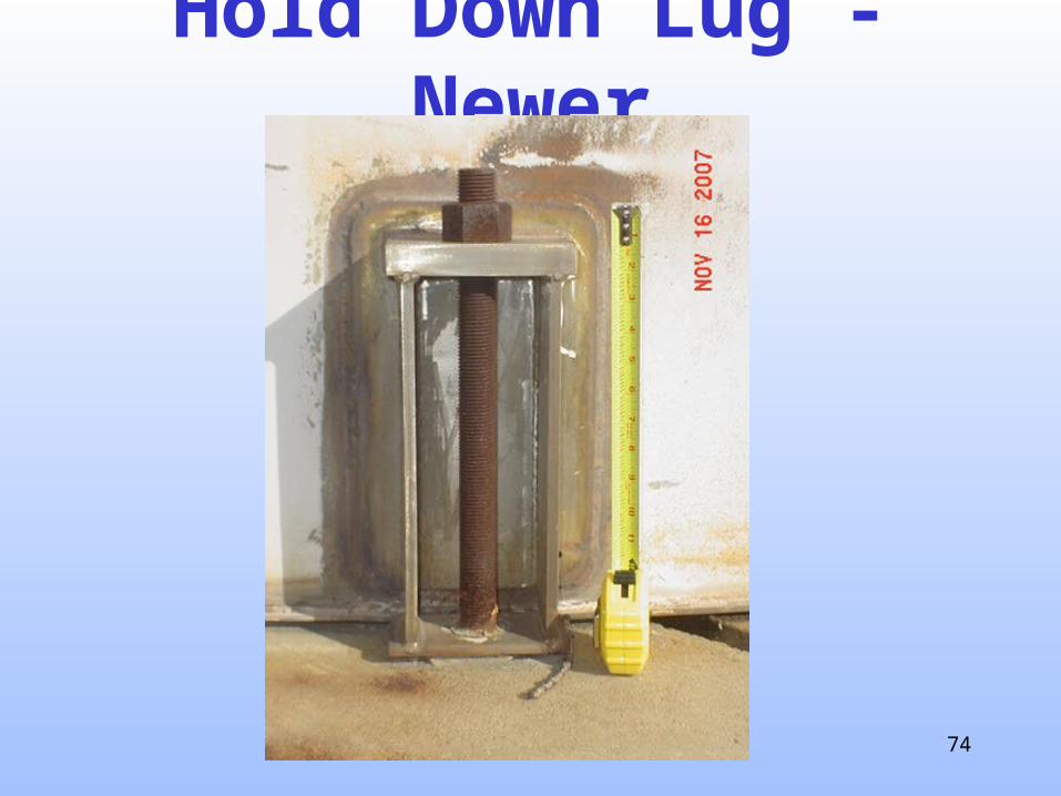
74
Hold Down Lug - Newer
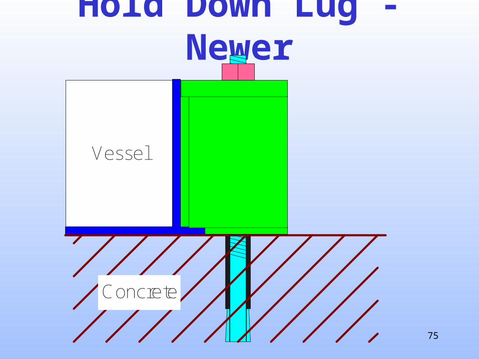
75
Hold Down Lug - Newer
Vessel
Concrete
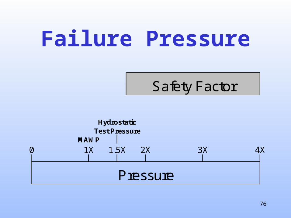
76
Failure Pressure
Safety Factor
HydrostaticTest Pressure
MAWP
0 1X 1.5X 2X 3X 4X
Pressure

77
Relief Devices
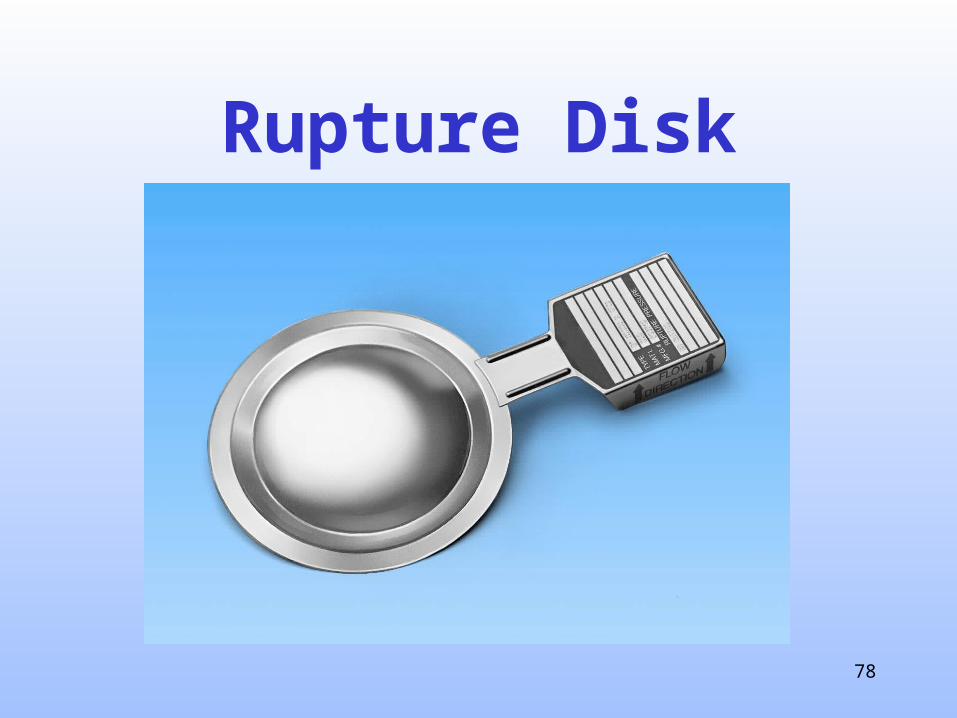
78
Rupture Disk

79
Tension-loaded RD
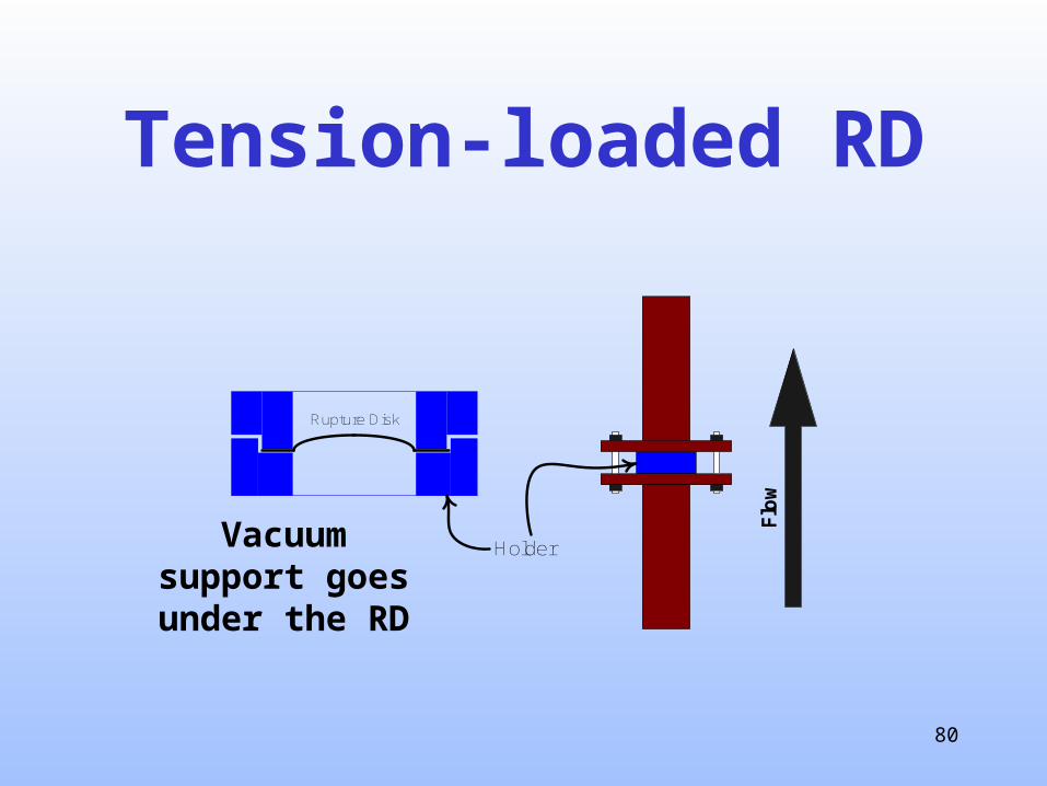
80
Tension-loaded RD
Flo
w
Rupture Disk
HolderVacuum support goes under the RD
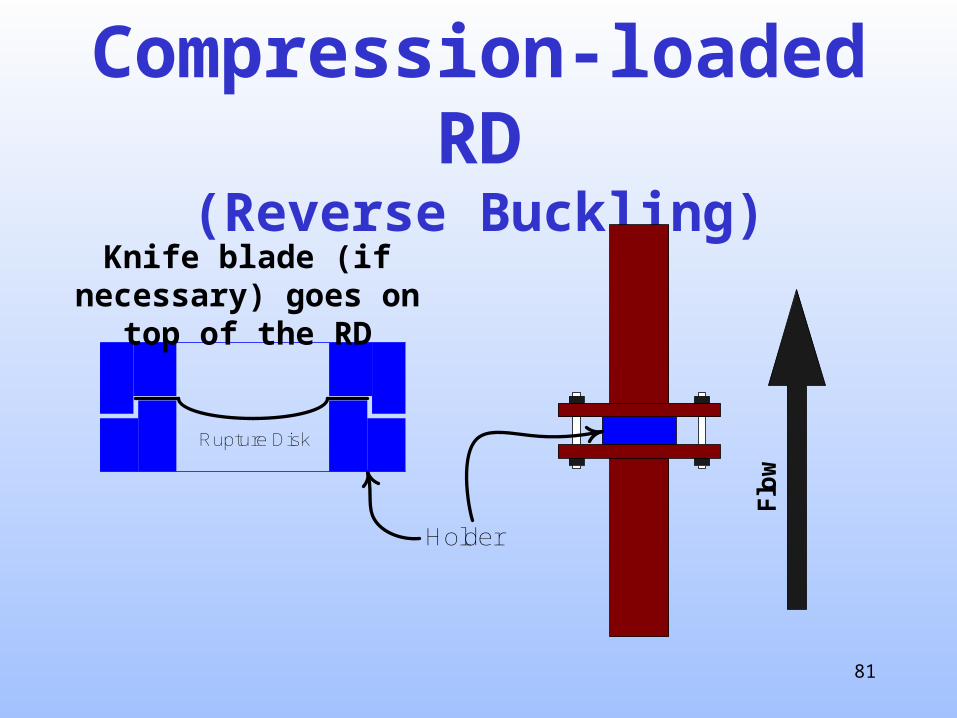
81
Compression-loaded RD(Reverse Buckling)
Flo
w
Rupture Disk
Holder
Knife blade (if necessary) goes on top of the RD

82
Relief Valves

83
Weak Seam Roof(part of API 650)
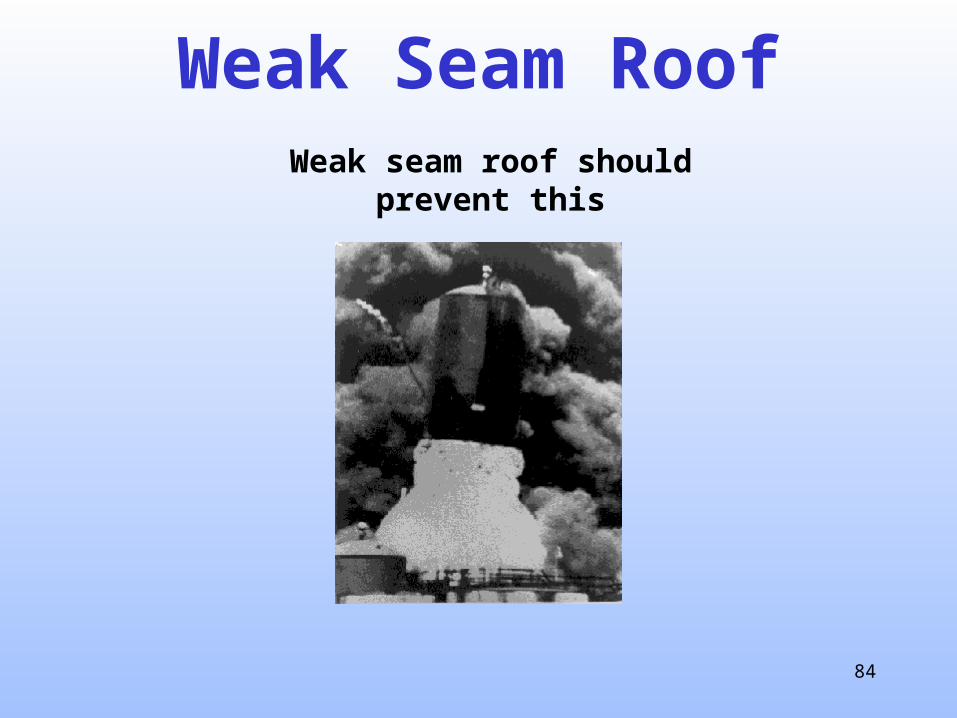
84
Weak Seam RoofWeak seam roof should prevent this
85
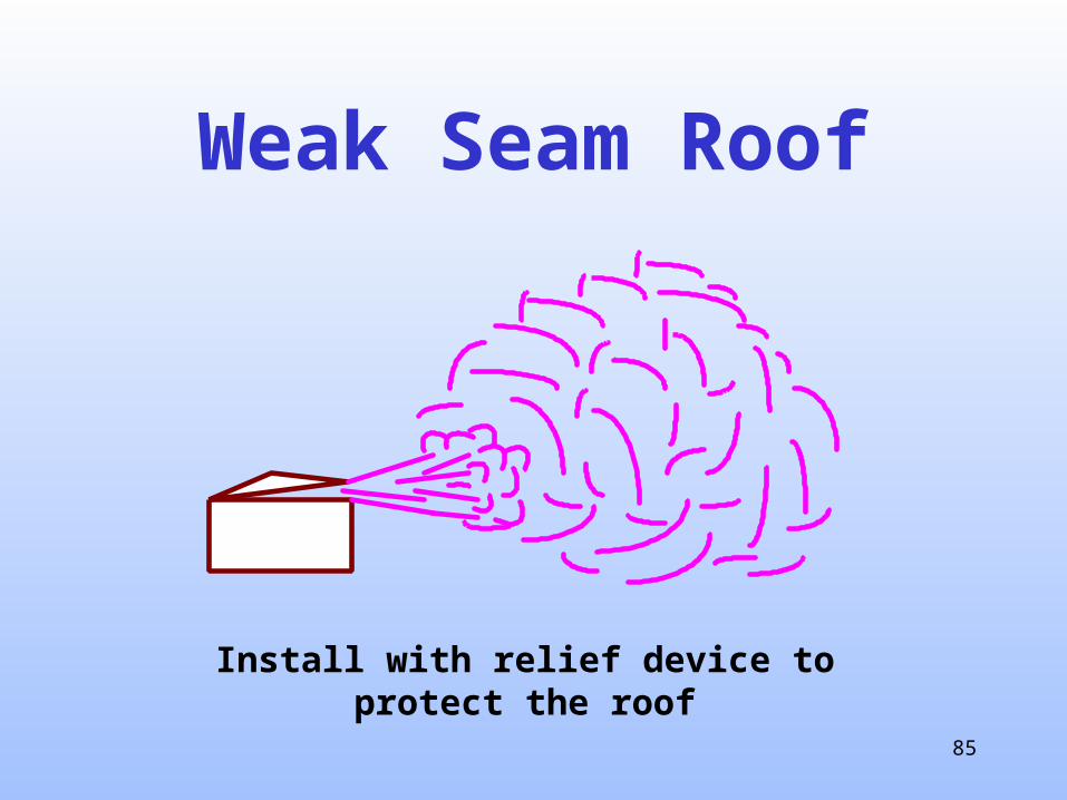
Weak Seam Roof
Install with relief device to protect the roof
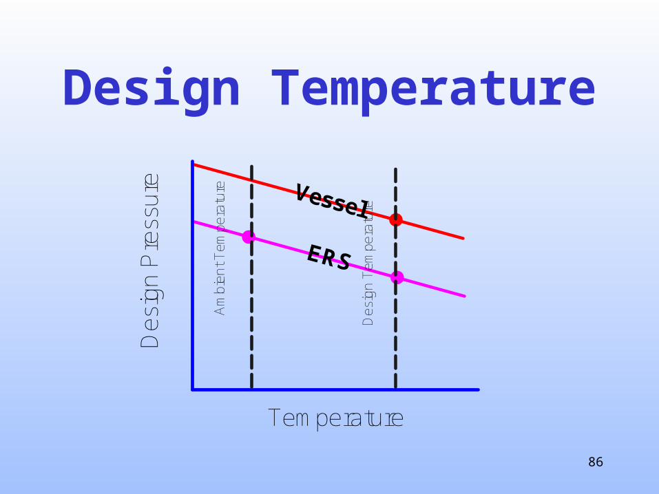
86
Design Temperature
ERS
Vessel
Temperature
Des
ign
Pre
ssur
e
Am
bien
t Tem
pera
ture
Des
ign
Tem
pera
ture

87
Thrust forces
88
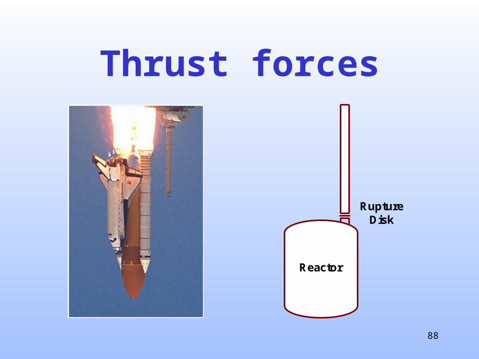
Thrust forces
RuptureDisk
Reactor
89
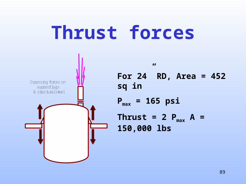
Thrust forces
For 24” RD, Area = 452 sq in
Pmax = 165 psi
Thrust = 2 Pmax A = 150,000 lbs
Opposing forces onsupport lugs
& structural steel

90
Piping – Thrust forces(initial & established)
Initial load
Established load
91
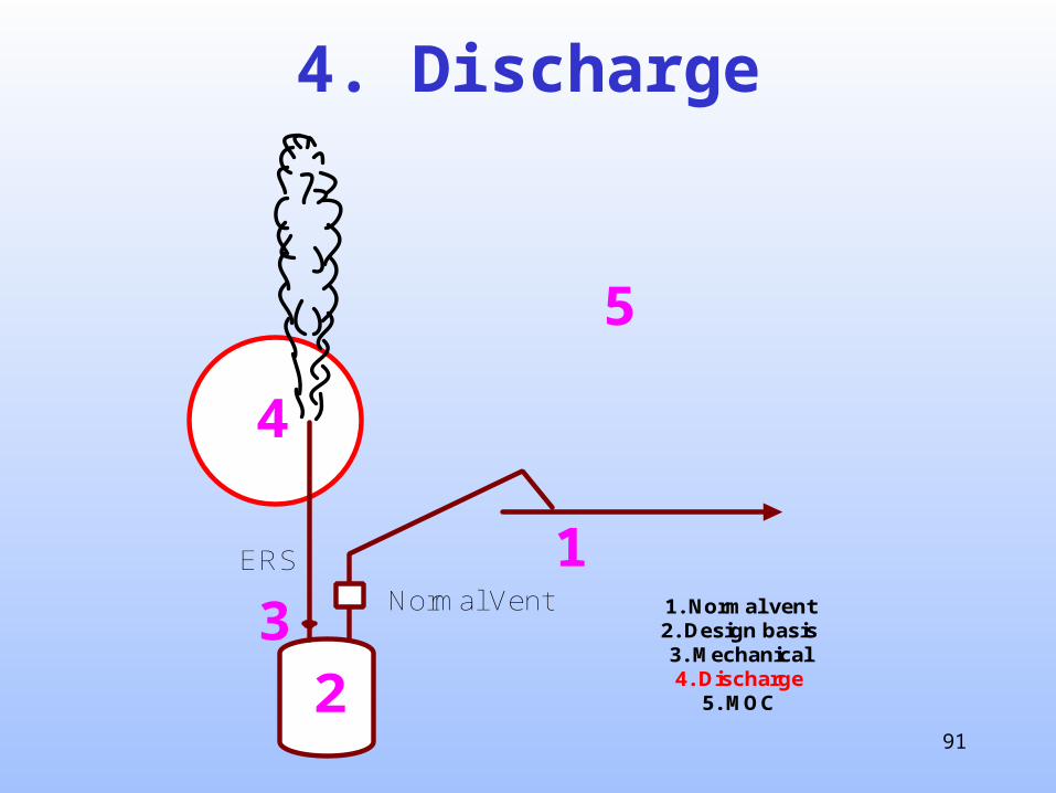
4. Discharge
ERS
Normal Vent
1
23
4
5
1. Normal vent2. Design basis3. Mechanical4. Discharge
5. MOC

92
Dispersion Zones1. High momentum2. Less momentum3. Gravity4. Atmospheric
turbulence
1
2 3
4

93
2-phase Flow
1 3
4 5 6
2
94
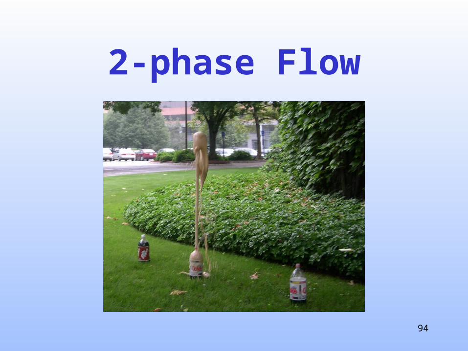
2-phase Flow

95
PHAST – Emulsion Reactor RD
96
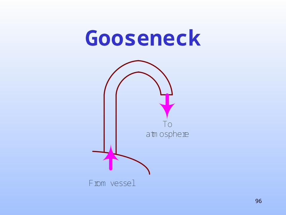
Gooseneck
Toatmosphere
From vessel

97
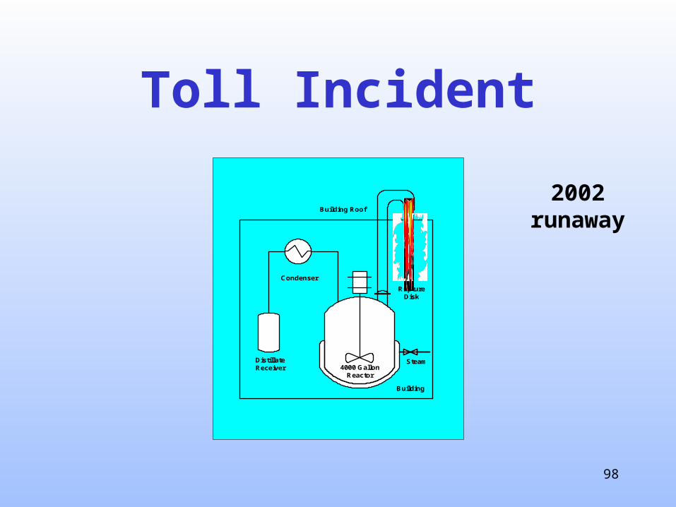
Toll Incident
• Wisconsin - 2002
• Leaky steam valve heated a completed batch from 40C to 150C in 3 hours
• Resulting decomposition (>200 psig)
• MSDS: “This material is considered stable”
• No fatalities or injuries .
98
Toll Incident
DistillateReceiver
Condenser
4000 GallonReactor
RuptureDisk
Building
Building Roof
Steam
2002 runaway

99
Toll Incident
2002 runaway

100
Toll Incident2002 runaway

101
TNP(Thrust Neutralization Plate)

102
TNPThrust Neutralization Plate

103
TNP or Gooseneckwind
typical flammable region
buildingair inlet
With an obstruction

104
Catch TankGravity Separator
Vapors still escape from a separator,
but at a lower
velocity.
105
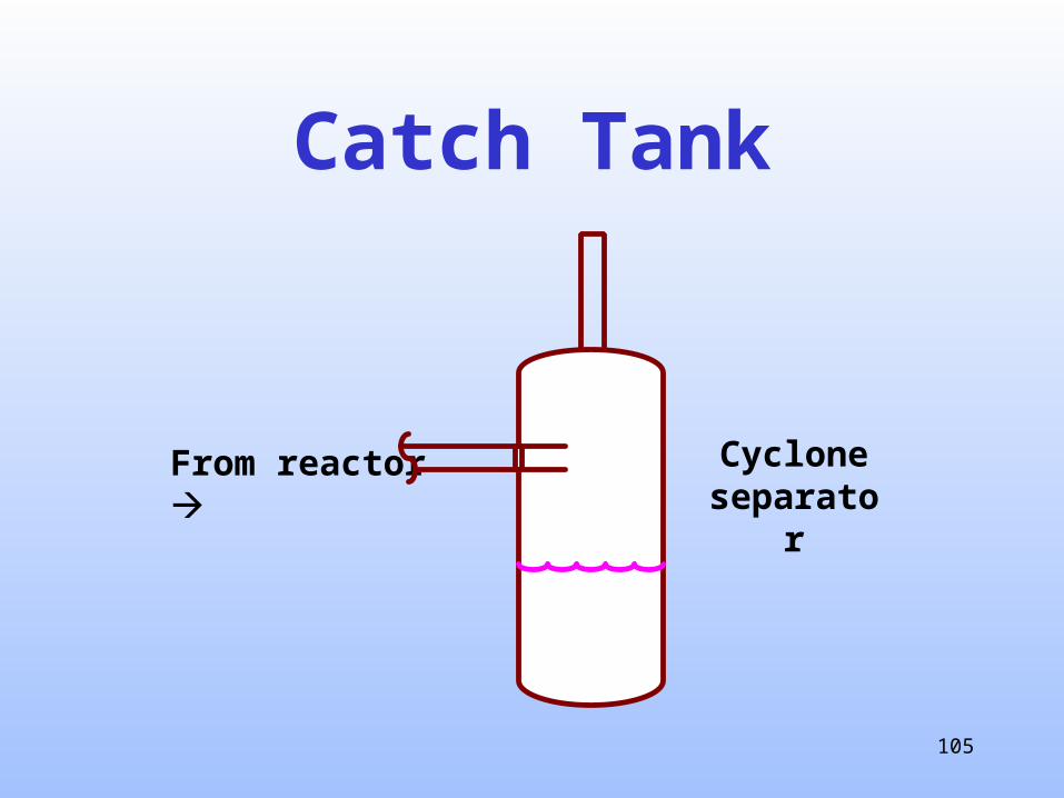
Catch Tank
From reactor Cyclone separator

106
Catch Tank Incident

107
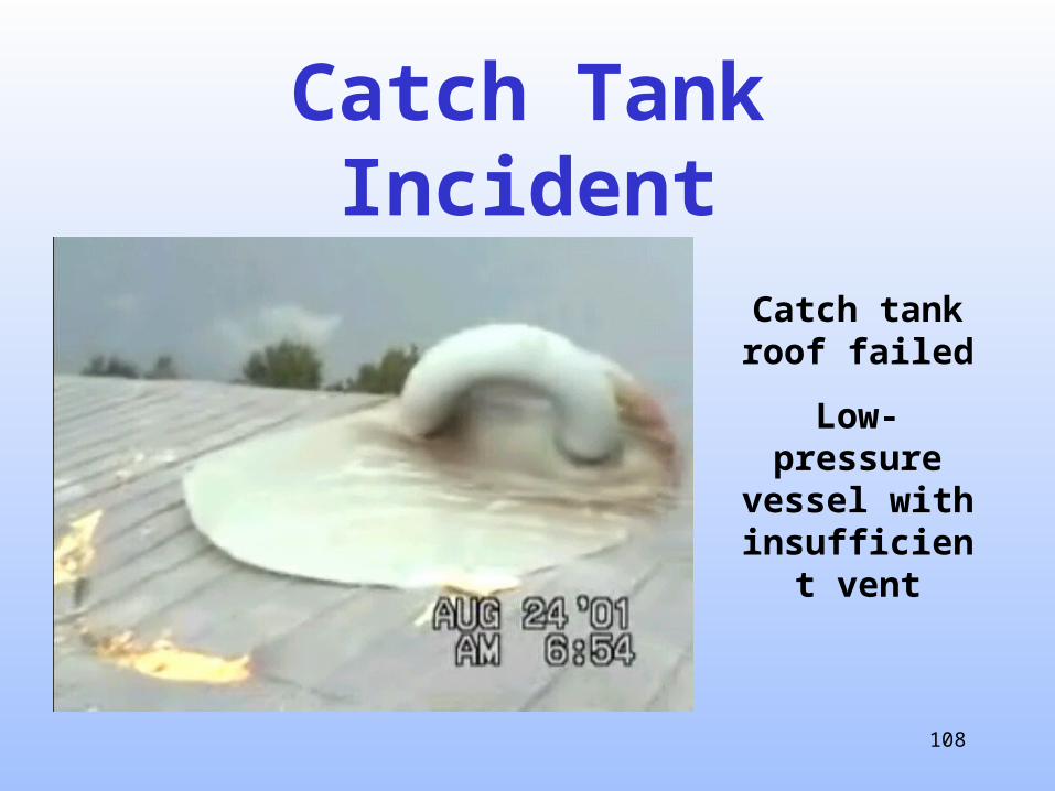
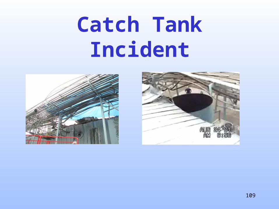
Catch Tank Incident• Illinois 2001• Runaway reaction
broke 135 psi RD• Blew off catch tank
top & damaged piping
• No injuries or fatalities .
108
Catch Tank Incident
Catch tank roof failed
Low-pressure vessel with
insufficient vent
109
Catch Tank Incident
110
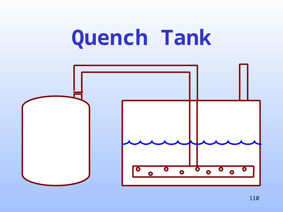
Quench Tank

111
Straight up
wind
112
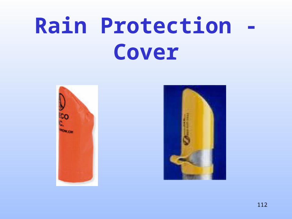
Rain Protection - Cover

113
5. MOC
ERS
Normal Vent
1
23
4
5
1. Normal vent2. Design basis3. Mechanical4. Discharge
5. MOC

114
Why document?
• Required by OSHA PSM (Process Safety Mgmt)
• Required by EHS 536 (Process Safety Mgmt)
• For future Management of Change (MOCs)
• For future HAZOPs
• Avoid reconstructing the design
• Information can be used on other systems .

115
Vent System Analysis
Follow the ERS procedure for every vessel & every relief device
Store the results in a safe place

116
Questions?