1. explain weak entity set, specialization, generalization. · explain weak entity set,...
TRANSCRIPT

www.ashishprajapati29.wordpress.com
1
1. Explain Weak entity set, Specialization, Generalization.
Answer:
Weak entity set: The entity set which does not have sufficient attributes to form a
primary key is called as Weak entity set.
Specialization: Specialization is the opposite of generalization. In specialization, a
group of entities is divided into sub-groups based on their characteristics. Take a group
‘Person’ for example. A person has name, date of birth, gender, etc. These properties
are common in all persons, human beings. But in a company, persons can be identified
as employee, employer, customer, or vendor, based on what role they play in the
company.
Figure-1. Specialization
Generalization: As mentioned above, the process of generalizing entities, where the generalized entities contain the properties of all the generalized entities, is called generalization. In generalization, a number of entities are brought together into one generalized entity based on their similar characteristics. For example, pigeon, house sparrow, crow and dove can all be generalized as Birds.
Figure-2. Generalization
2. Draw symbols for following in ER diagram- Relationship Set, and Primary
key attribute.
Answer:
Relationship Set: A set of relationships of similar type is called a relationship set. Like
entities, a relationship too can have attributes. These attributes are called descriptive
attributes.

www.ashishprajapati29.wordpress.com
2
Primary Key: The candidate key chosen to be used for identifying entities and accessing
records. Unless otherwise noted "key" means "primary key". In E-R diagram primary key
is defined by using Underline. In below figure the Name attribute is a primary key.
Figure-3. Relationship set with primary key.
3. Draw ER diagram for Library Management System.
Figure-4. Library Management System
4. What is Entity-Relationship model? Explain the steps to reduce the ER
diagram to ER database schema.
Answer:
Goal of design is to generate a formal specification of the database schema.

www.ashishprajapati29.wordpress.com
3
Methodology:
1. Use E-R model to get a high-level graphical view of essential components of enterprise
and how they are related
2. Then convert E-R diagram to SQL DDL, or whatever database model you are using
E-R Model is not SQL based. It's not limited to any particular DBMS. It is a conceptual
and semantic model – captures meanings rather than an actual implementation
The E-R Model: The enterprise is viewed as set of
Entities
Relationships among entities
Symbols used in E-R Diagram
Entity – rectangle
Attribute – oval
Relationship – diamond
Link – line
Figure-5. Symbols used in E-R Diagram
Steps to Reduced E-R diagram to E-R database schema (Table).
A database that conforms to an E-R database schema can be represented by a collection of
tables. For each entity set and for each relationship set, there is a unique table. A table is a
chart with rows and columns. The set of all possible rows is the Cartesian product of all
columns.
A row is also known as a tuple or a record. A table has an unlimited number of rows.
Each column is also known as a field.
Strong Entity Sets
It is common practice for the table to have the same name as the entity set. There is one
column for each attribute.
Weak Entity Sets
There is one column for each attribute, plus the attribute(s) the form the primary key of the
strong entity set that the weak entity set depends upon.
Relationship Sets
We represent a relationship with a table that includes the attributes of each of the primary
keys plus any descriptive attributes (if any).

www.ashishprajapati29.wordpress.com
4
There is a problem that if one of the entities in the relationship is a weak entity set, there
would be no unique information in the relationship table, and therefore may be omitted.
Another problem can occur if there is an existence dependency. In that case, you can
combine the two tables.
Multivalued Attributes
When an attribute is multivalued, remove the attribute from the table and create a new table
with the primary key and the attribute, but each value will be a separate row.
Generalization
Create a table for the higher-level entity set. For each lower-level entity set, create a table
with the attributes for that specialization and include the primary key from the higher-level
entity set.
5. Explain Mapping Cardinalities.
Answer:
Cardinality defines the number of entities in one entity set, which can be associated with
the number of entities of other set via relationship set.
One-to-one − One entity from entity set A can be associated with at most one entity of
entity set B and vice versa.
Figure-6. One to one relation.
One-to-many − One entity from entity set A can be associated with more than one
entities of entity set B however an entity from entity set B, can be associated with at
most one entity.

www.ashishprajapati29.wordpress.com
5
Figure-7. One to Many Relation.
Many-to-one − More than one entities from entity set A can be associated with at
most one entity of entity set B, however an entity from entity set B can be associated
with more than one entity from entity set A.
Figure-8. Many to one relation.
Many-to-many − One entity from A can be associated with more than one entity
from B and vice versa.
Figure-9. Many to Many relation.
6. Explain 1NF, 2NF, 3NF and BCNF.
Answer:
While designing a database out of an entity–relationship model, the main problem existing
in that “raw” database is redundancy. Redundancy is storing the same data item in more
one place. A redundancy creates several problems like the following:
Extra storage space: storing the same data in many places takes large amount of disk
space.
Entering same data more than once during data insertion.
Deleting data from more than one place during deletion.
Modifying data in more than one place.

www.ashishprajapati29.wordpress.com
6
Anomalies may occur in the database if insertion, deletion, modification etc. are no
done properly.
It creates inconsistency and unreliability in the database. To solve this problem, the “raw”
database needs to be normalized. This is a step by step process of removing different kinds
of redundancy and anomaly at each step. At each step a specific rule is followed to remove
specific kind of impurity in order to give the database a slim and clean look.
Un-Normalized Form (UNF)
If a table contains non-atomic values at each row, it is said to be in UNF. An atomic value
is something that cannot be further decomposed. A non-atomic value, as the name suggests,
can be further decomposed and simplified.
Example relation: EMPLOYEE (Name, Project, Task, Office, Floor, Phone)
Note: Keys are underlined.
Table-1. Un-Normalized Table.
Name Project Task Office Floor Phone
Bill 100X T1,T2 400 4 1400
Bill 200Y T1,T2 400 4 1400
Sue 100X,200Y,300Z T33 442 4 1442
Ed 100X T2 588 5 1588
First Normalization:
Rules for 1NF (First Normal Form):
No column or attribute should have a repeated or similar data.
Every attribute should have atomic value.
Each row is unique.
Each attribute should have a value, it cannot be empty.
Any one attribute should have a primary key and no null values are accepted.

www.ashishprajapati29.wordpress.com
7
Table-2. Converting UNF to First Normalization.
Name Project Task Office Floor Phone
Bill 100X T1 400 4 1400
Bill 100X T2 400 4 1400
Bill 200Y T1 400 4 1400
Bill 200Y T2 400 4 1400
Sue 100X T33 422 4 1422
Sue 200Y T3c3 422 4 1422
Sue 300Z T33 422 4 1422
Ed 100X T2 588 5 1588
Second Normalization:
Rules for 2NF (Second Normal Form):
Table should already exist in 1NF.
All the non-key attribute fully functionally depends on all key-attribute or primary key.
Here in above example the functional dependencies are,
1. Name, Project, Task Office, Floor, Phone.
2. Name Office, Floor, Phone.
Table-3. Employee_Project_Task Details
Name Project Task
Bill 100X T1
Bill 100X T2
Bill 200Y T1
Bill 200Y T2
Sue 100X T33
Sue 200Y T33

www.ashishprajapati29.wordpress.com
8
Sue 300Z T33
Ed 100X T2
Table-4. Employee Details.
Name Office Floor Phone
Bill 400 4 1400
Sue 442 4 1442
Ed 588 5 1588
Third Normalization:
Rules for 3NF (Third Normal Form):
Table should already exist in 2NF.
Non-key attributes should not be dependent on any non-key attributes.
Table should not follow transitive rule (AB, BC, CA).
Here, table-3 is already in 3NF, because there is no non-key attribute and it does not follow
transitive rule. But, table-4 is not in 3NF. In table-4, phone is depends on office and office
is also depends on phone and both are Non key attributes. It also follows the transitive rule.
So, we have to convert it into 3NF form. After converting into 3NF at final we get 2 more
tables as given below.
Functional Dependencies are:
1. Name Office, Floor.
2. Office Phone. Table-5. Name_office_Floor Details.
Name Office Floor
Bill 400 4
Sue 442 4
Ed 588 5
Table-6. Office_Phone Details.
Office Phone
400 1400
442 1442
588 1588

www.ashishprajapati29.wordpress.com
9
BCNF(BOYCE CODD NORMAL FORM):
Rules for BCNF (Boyce-Codd Normal Form):
Table should already exist in 3NF.
A relation which is in 3NF is almost always in BCNF.
Key attributes cannot be derived by any non-key attributes.
From above example, table-3, 5 and 6 are already in BCNF.
7. Why do we need normalization? Explain 4NF & 5NF.
Normalization is the process to convert the un-normalized form to normalized form. It is a
technique of organizing data in the database. It is a multi-step process that puts data into
the tabular form by removing duplicated data from the relation tables. It is a systematic
approach of decomposing tables to eliminate data redundancy and undesirable
characteristics like insertion, update and deletion anomalies.
Advantages Of Normalization
The database doesn’t have redundant data.
It is smaller is in size, so it require less space for storage.
There is no duplication of the data.
There is better data integrity and less risk of mistake.
It is easy and faster to run a query on the data.
Disadvantages Of Normalization
After table is normalized as there are more than one tables so it is difficult to fetch the
data and perform query.
As there are more than one tables so it is hard to apply queries and it can become more
difficult and complex to perform.
Need to be careful with trying to make data atomic.
As there are more tables so it requires more space to store.
Fourth Normalization:
Rules for 4NF (Fourth Normal Form):
Table should already exist in 3NF or in BCNF.
The table should not have more than one multi valued dependency.
www.ashishprajapati29.wordpress.com
10
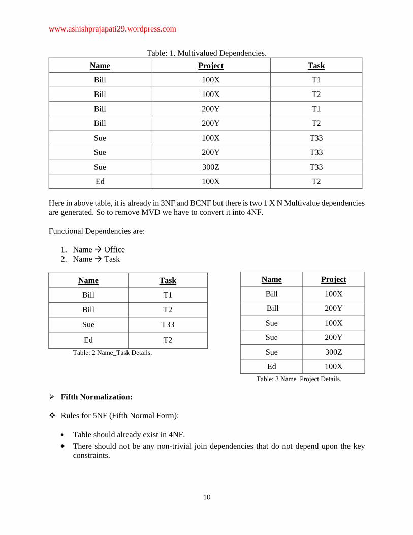
Table: 1. Multivalued Dependencies.
Name Project Task
Bill 100X T1
Bill 100X T2
Bill 200Y T1
Bill 200Y T2
Sue 100X T33
Sue 200Y T33
Sue 300Z T33
Ed 100X T2
Here in above table, it is already in 3NF and BCNF but there is two 1 X N Multivalue dependencies
are generated. So to remove MVD we have to convert it into 4NF.
Functional Dependencies are:
1. Name Office
2. Name Task
Name Task
Bill T1
Bill T2
Sue T33
Ed T2
Table: 2 Name_Task Details.
Table: 3 Name_Project Details.
Fifth Normalization:
Rules for 5NF (Fifth Normal Form):
Table should already exist in 4NF.
There should not be any non-trivial join dependencies that do not depend upon the key
constraints.
Name Project
Bill 100X
Bill 200Y
Sue 100X
Sue 200Y
Sue 300Z
Ed 100X

www.ashishprajapati29.wordpress.com
11
8. Explain disadvantages of conventional file-based system compared to
Database management system.
Answer: Major disadvantages of file system when compared to database management systems are
as follows:
Data Redundancy- The files are created in the file system as and when required by an enterprise
over its growth path. So in that case the repetition of information about an entity cannot be
avoided. Eg. The addresses of customers will be present in the file maintaining information about
customers holding savings account and also the address of the customers will be present in file
maintaining the current account. Even when same customers have a saving account and current
account his address will be present at two places.
Data Inconsistency: Data redundancy leads to greater problem than just wasting the storage i.e.
it may lead to inconsistent data. Same data which has been repeated at several places may not
match after it has been updated at some places. For example: Suppose the customer requests to
change the address for his account in the Bank and the Program is executed to update the
saving bank account file only but his current bank account file is not updated. Afterwards the
addresses of the same customer present in saving bank account file and current bank account file
will not match. Moreover there will be no way to find out which address is latest out of these
two.
Difficulty in Accessing Data: For generating ad hoc reports the programs will not already be
present and only options present will to write a new program to generate requested report or to
work manually. This is going to take impractical time and will be more expensive. For example:
Suppose all of sudden the administrator gets a request to generate a list of all the customers
holding the saving banks account who lives in particular locality of the city. Administrator will
not have any program already written to generate that list but say he has a program which can
generate a list of all the customers holding the savings account. Then he can either provide
the information by going thru the list manually to select the customers living in the particular
locality or he can write a new program to generate the new list. Both of these ways will take
large time which would generally be impractical.
Data Isolation: Since the data files are created at different times and supposedly by different
people the structures of different files generally will not match. The data will be scattered in
different files for a particular entity. So it will be difficult to obtain appropriate data. For
example: Suppose the Address in Saving Account file have fields: Add line1, Add line2, City,
State, Pin while the fields in address of Current account are: House No., Street No.1, Locality,
City, State, and Pin. Administrator is asked to provide the list of customers living in a particular
locality. Providing consolidated list of all the customers will require looking in both files. But
they both have different way of storing the address. Writing a program to generate such a list
will bé difficulté.
Integrity Problems: All the consistency constraints have to be applied to database through
appropriate checks in the coded programs. This is very difficult when number such constraint is

www.ashishprajapati29.wordpress.com
12
very large. For example: An account should not have balance less than Rs. 500. To enforce this
constraint appropriate check should be added in the program which add a record and the program
which withdraw from an account. Suppose later on this amount limit is increased then all those
check should be updated to avoid inconsistency. These time to time changes in the programs
will be great headache for the administrator.
Security and access control: Database should be protected from unauthorized users. Every user
should not be allowed to access every data. Since application programs are added to the system
For example: The Payroll Personnel in a bank should not be allowed to access accounts
information of the customers.
Concurrency Problems: When more than one users are allowed to process the database. If in
that environment two or more users try to update a shared data element at about the same time
then it may result into inconsistent data. For example: Suppose Balance of an account is Rs. 500.
And User A and B try to withdraw Rs 100 and Rs 50 respectively at almost the same time using
the Update process.
9. Write short note on Relational Algebra.
Answer:
Relational algebra is a procedural query language, which takes Instances of relations as
input and yields instances of relations as output. It is operators to perform queries. An
operator can be either unary or binary. They accept relations as their input and yield
relations as their output. Relational algebra is performed recursively on a relation and
intermediate results are also considered relations.
The fundamental operations of relational algebra are as follows −
• Select
• Project
• Union
• Set different
• Cartesian product
• Rename
10. Explain three level architecture of DBMS.
Answer:
A 3-tier architecture separates its tiers from each other based on the complexity of the users
and how they use the data present in the database. It is the most widely used architecture
to design a DBMS.

www.ashishprajapati29.wordpress.com
13
Figure: Three level architecture of DBMS.
Database (Data) Tier − At this tier, the database resides along with its query processing
languages. We also have the relations that define the data and their constraints at this level.
Application (Middle) Tier − At this tier reside the application server and the programs
that access the database. For a user, this application tier presents an abstracted view of the
database. End-users are unaware of any existence of the database beyond the application.
At the other end, the database tier is not aware of any other user beyond the application
tier. Hence, the application layer sits in the middle and acts as a mediator between the end-
user and the database.
User (Presentation) Tier − End-users operate on this tier and they know nothing about
any existence of the database beyond this layer. At this layer, multiple views of the
database can be provided by the application. All views are generated by applications that
reside in the application tier.
11. What is deadlock? Explain deadlock detection and prevention policies.
Answer:
In a multi-process system, deadlock is an unwanted situation that arises in a shared resource
environment, where a process indefinitely waits for a resource that is held by another
process. Deadlocks are not healthy for a system. In case a system is stuck in a deadlock,
the transactions involved in the deadlock are either rolled back or restarted.

www.ashishprajapati29.wordpress.com
14
Deadlock Prevention
To prevent any deadlock situation in the system, the DBMS aggressively inspects all the
operations, where transactions are about to execute. The DBMS inspects the operations
and analyses if they can create a deadlock situation. If it finds that a deadlock situation
might occur, then that transaction is never allowed to be executed.
There are deadlock prevention schemes that use timestamp ordering mechanism of
transactions in order to predetermine a deadlock situation.
Wait-Die Scheme
In this scheme, if a transaction requests to lock a resource (data item), which is already
held with a conflicting lock by another transaction, then one of the two possibilities may
occur −
If TS(Ti) < TS(Tj) − that is Ti, which is requesting a conflicting lock, is older than Tj −
then Ti is allowed to wait until the data-item is available.
If TS(Ti) > TS(tj) − that is Ti is younger than Tj − then Ti dies. Ti is restarted later with a
random delay but with the same timestamp.
This scheme allows the older transaction to wait but kills the younger one.
Wound-Wait Scheme
In this scheme, if a transaction requests to lock a resource (data item), which is already
held with conflicting lock by some another transaction, one of the two possibilities may
occur −
If TS(Ti) < TS(Tj), then Ti forces Tj to be rolled back − that is Ti wounds Tj. Tj is restarted
later with a random delay but with the same timestamp.
If TS(Ti) > TS(Tj), then Ti is forced to wait until the resource is available.
This scheme, allows the younger transaction to wait; but when an older transaction requests
an item held by a younger one, the older transaction forces the younger one to abort and
release the item.
In both the cases, the transaction that enters the system at a later stage is aborted.
Deadlock Detection
Aborting a transaction is not always a practical approach. Instead, deadlock avoidance
mechanisms can be used to detect any deadlock situation in advance. Methods like "wait-
for graph" are available but they are suitable for only those systems where transactions are
lightweight having fewer instances of resource. In a bulky system, deadlock prevention
techniques may work well.
Wait-for Graph
This is a simple method available to track if any deadlock situation may arise. For each
transaction entering into the system, a node is created. When a transaction Ti requests for
a lock on an item, say X, which is held by some other transaction Tj, a directed edge is

www.ashishprajapati29.wordpress.com
15
created from Ti to Tj. If Tj releases item X, the edge between them is dropped and Ti locks
the data item.
The system maintains this wait-for graph for every transaction waiting for some data items
held by others. The system keeps checking if there's any cycle in the graph.
Here, we can use any of the two following approaches −
First, do not allow any request for an item, which is already locked by another
transaction. This is not always feasible and may cause starvation, where a transaction
indefinitely waits for a data item and can never acquire it.
The second option is to roll back one of the transactions. It is not always feasible to roll
back the younger transaction, as it may be important than the older one. With the help of
some relative algorithm, a transaction is chosen, which is to be aborted. This transaction
is known as the victim and the process is known as victim selection.
12. Write a PL/SQL block to print the sum of first 10 numbers.
Answer:
SQL> set serveroutput on;
SQL> declare
2 s number (3):=0;
3 n number (3):=1;
4 begin
5 while n<=10
6 loop
7 s:=s+n;
8 n:=n+1;
9 end loop;
10 dbms_output.put_line ('Ans='||s);
11 end;
12 /
Output:
Ans=55

www.ashishprajapati29.wordpress.com
16
13. Write a PL/SQL block to find the given number is odd or even. Answer:
SQL> set serveroutput on;
SQL> declare
2 i number (3):=&i;
3 begin
4 if mod (i, 2) = 0 then
5 dbms_output.put_line (‘given number is Even’);
6 else
7 dbms_output.put_line (‘given number is Odd’);
8 end if;
9 end;
10 /
Output:
Enter value for i = 4
given number id even