1 final conference, 19th – 23rd january 2015 geneva, switzerland rp 7 remote handling concept...
TRANSCRIPT
1Final Conference, 19th – 23rd January 2015Geneva, Switzerland
RP 7
Remote Handling Concept Study for theSuper-FRS Plug System
Luis M. Orona D.Helmut WeickGSI Helmholtzzentrum
Project: 02/12 – 01/15
A Systematic Approach to Define, Analyse and Develop Remote Handling Tasks in Radiation Areas
2Final Conference, 19th – 23rd January 2015Geneva, Switzerland
Outline
• Background information• Super-FRS target area remote handling• Remote handling• My research• Summary

3Final Conference, 19th – 23rd January 2015Geneva, Switzerland
Background Information
• Luis M. Orona D.• Dr. Helmut Weick• GSI Helmholtzzentrum - Germany
• Tampere Univeristy of Technology (TUT) - Finland• Prof. Jouni Mattila
4Final Conference, 19th – 23rd January 2015Geneva, Switzerland
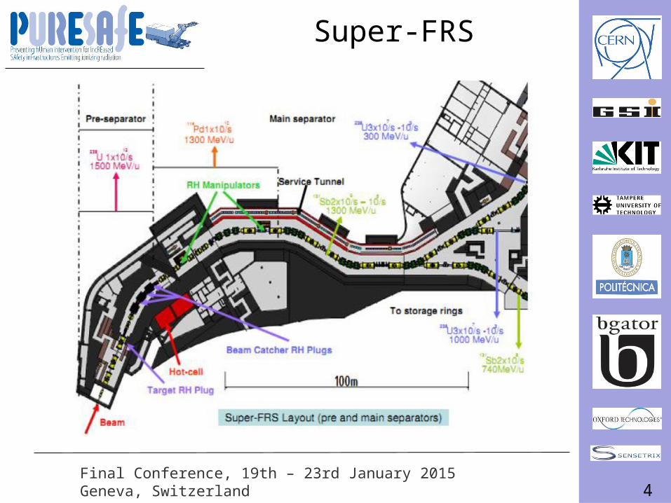
Super-FRS
5Final Conference, 19th – 23rd January 2015Geneva, Switzerland
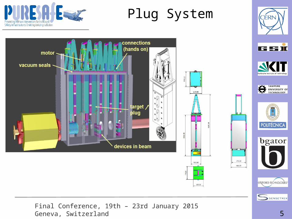
Plug System
6Final Conference, 19th – 23rd January 2015Geneva, Switzerland
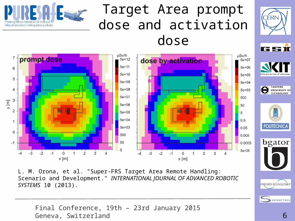
Target Area prompt dose and activation dose
L. M. Orona, et al. "Super-FRS Target Area Remote Handling: Scenario and Development." INTERNATIONAL JOURNAL OF ADVANCED ROBOTIC SYSTEMS 10 (2013).
7Final Conference, 19th – 23rd January 2015Geneva, Switzerland
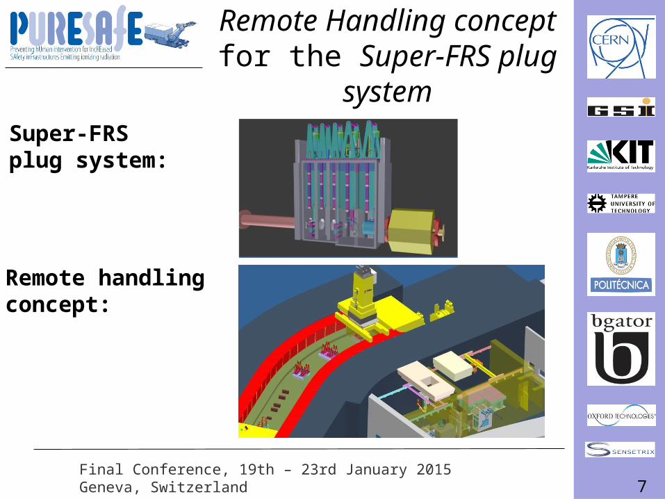
Remote Handling concept for the Super-FRS plug
systemSuper-FRS plug system:
Remote handling concept:
8Final Conference, 19th – 23rd January 2015Geneva, Switzerland
9Final Conference, 19th – 23rd January 2015Geneva, Switzerland
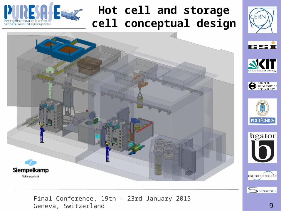
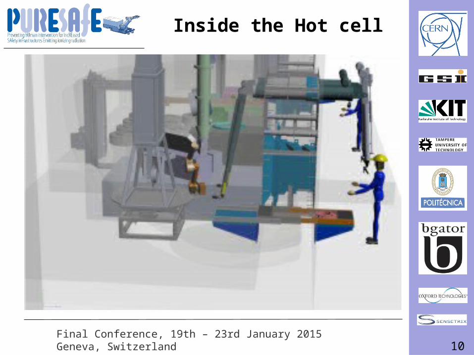
Hot cell and storage cell conceptual design
10Final Conference, 19th – 23rd January 2015Geneva, Switzerland
Inside the Hot cell
11Final Conference, 19th – 23rd January 2015Geneva, Switzerland
About Remote Handling (RH)
12Final Conference, 19th – 23rd January 2015Geneva, Switzerland
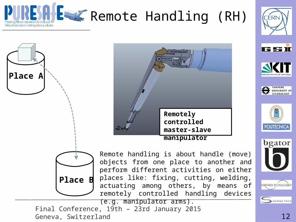
Remote Handling (RH)
Place A
Place B
Remotely controlled master-slave manipulator
Remote handling is about handle (move) objects from one place to another and perform different activities on either places like: fixing, cutting, welding, actuating among others, by means of remotely controlled handling devices (e.g. manipulator arms).

13Final Conference, 19th – 23rd January 2015Geneva, Switzerland
My research work
How to conduct a remote handling study?
14Final Conference, 19th – 23rd January 2015Geneva, Switzerland
How to conduct the remote handling concept study?
• Given that the Super-FRS plug system comprises many different components and several RH tasks can be identified and therefore must be analyzed.
• The proposed approach is to define a framework to systematically define, analyze and develop RH tasks.
15Final Conference, 19th – 23rd January 2015Geneva, Switzerland
Research Goals:• To develop a framework to systematically define, analyze
and develop remote handling maintenance tasks. • To provide groundwork to formalize remote handling beyond
good practices and design guidelines into a more analytical approach.
• To increase the understanding about remote handling due to ionizing radiation environments.
• To generate in deep knowledge for the design and development of the Super-FRS target area plug system with respect to remote handling.
Research Goals and Results
16Final Conference, 19th – 23rd January 2015Geneva, Switzerland
Research Goals and Results
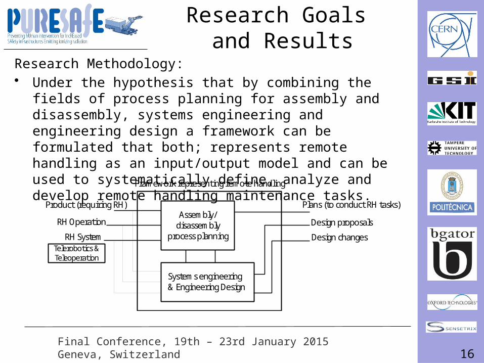
Research Methodology:• Under the hypothesis that by combining the fields of process
planning for assembly and disassembly, systems engineering and engineering design a framework can be formulated that both; represents remote handling as an input/output model and can be used to systematically define, analyze and develop remote handling maintenance tasks.
C
A
Product (requiring RH)
RH System
RH Operation
Plans (to conduct RH tasks)
Design changes
Design proposals
Framework representing remote handling
Systems engineering & Engineering Design
Assembly/ disassembly
process planning Telerobotics & Teleoperation
17Final Conference, 19th – 23rd January 2015Geneva, Switzerland
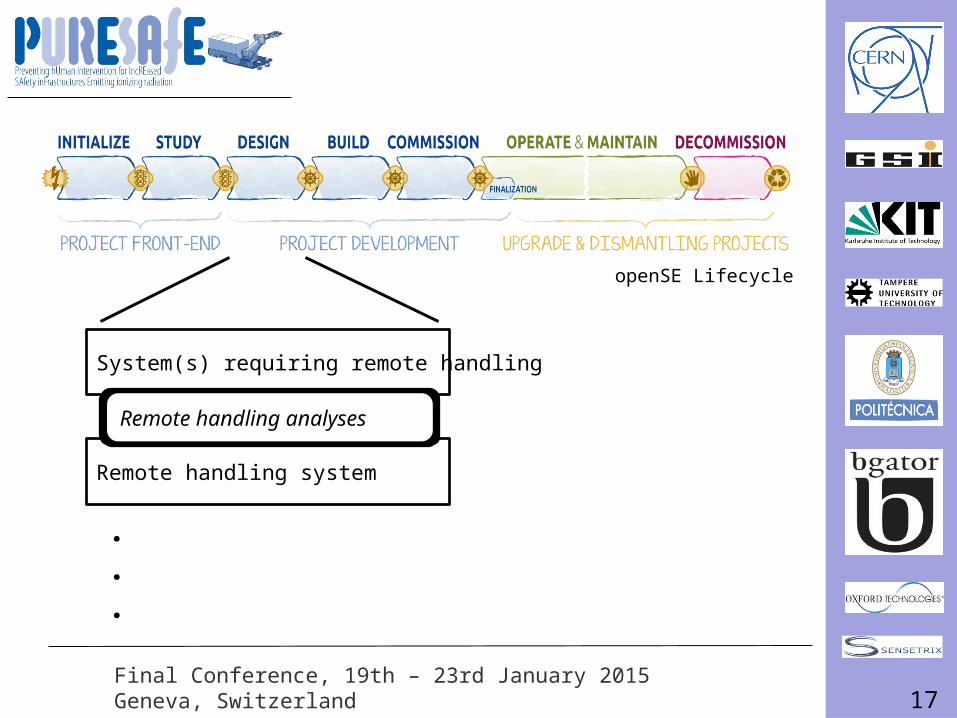
System(s) requiring remote handling
Remote handling system
Remote handling analyses
.
.
.
openSE Lifecycle
18Final Conference, 19th – 23rd January 2015Geneva, Switzerland
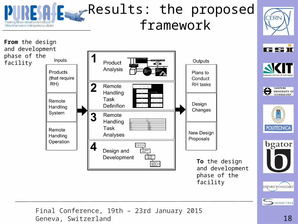
Results: the proposed framework
From the design and development phase of the facility
To the design and development phase of the facility
19Final Conference, 19th – 23rd January 2015Geneva, Switzerland
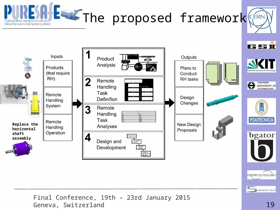
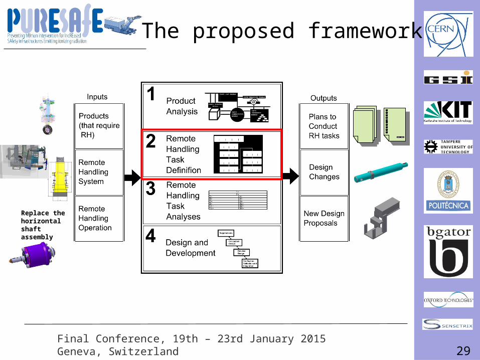
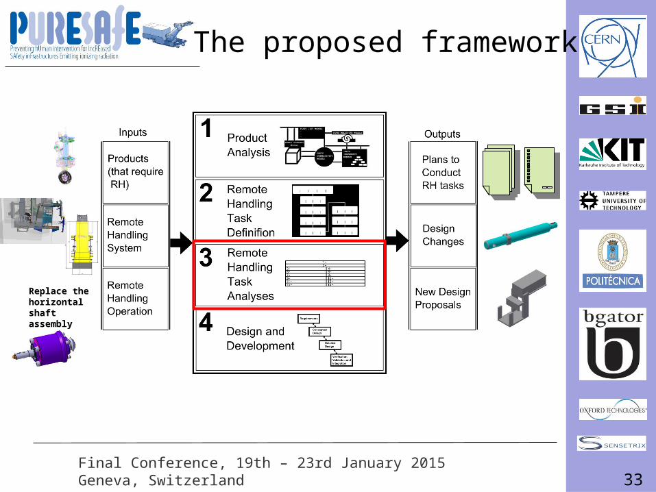
The proposed framework
Replace the horizontal shaft assembly
20Final Conference, 19th – 23rd January 2015Geneva, Switzerland
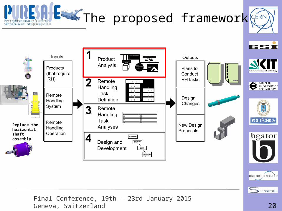
The proposed framework
Replace the horizontal shaft assembly
21Final Conference, 19th – 23rd January 2015Geneva, Switzerland
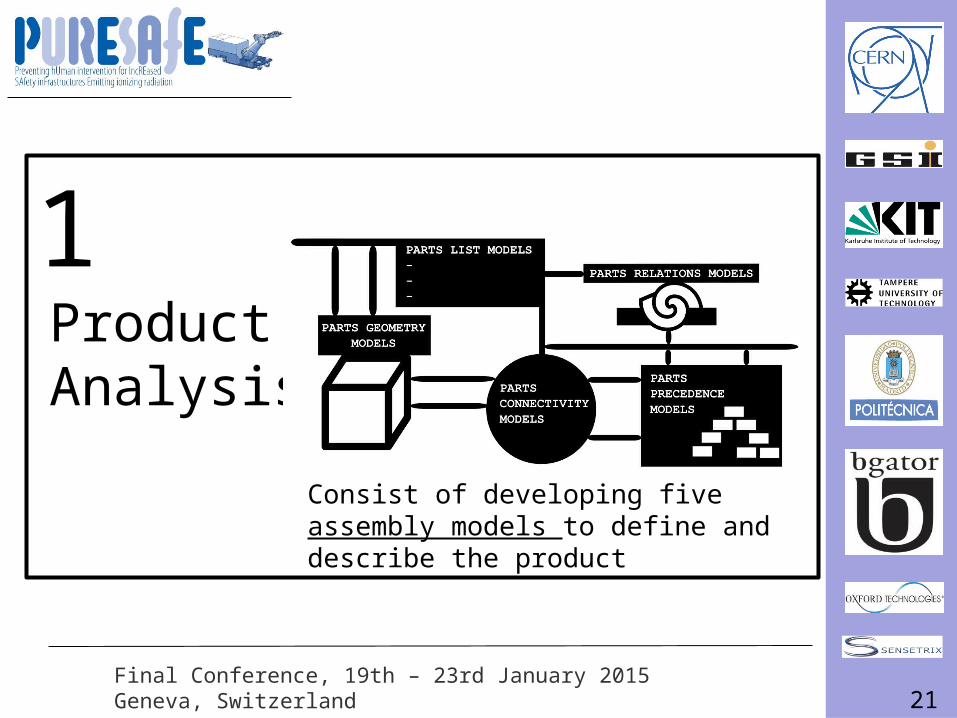
ProductAnalysis
1
Consist of developing five assembly models to define and describe the product
22Final Conference, 19th – 23rd January 2015Geneva, Switzerland
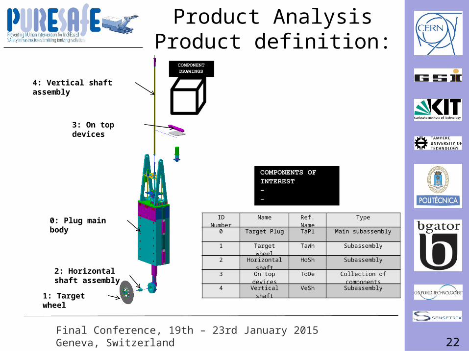
Product AnalysisProduct definition:
4: Vertical shaft assembly
2: Horizontal shaft assembly
1: Target wheel
3: On top devices
0: Plug main bodyID Number Name Ref. Name Type
0 Target Plug TaPl Main subassembly
1 Target wheel TaWh Subassembly
2 Horizontal shaft HoSh Subassembly
3 On top devices ToDe Collection of components
4 Vertical shaft VeSh Subassembly
23Final Conference, 19th – 23rd January 2015Geneva, Switzerland
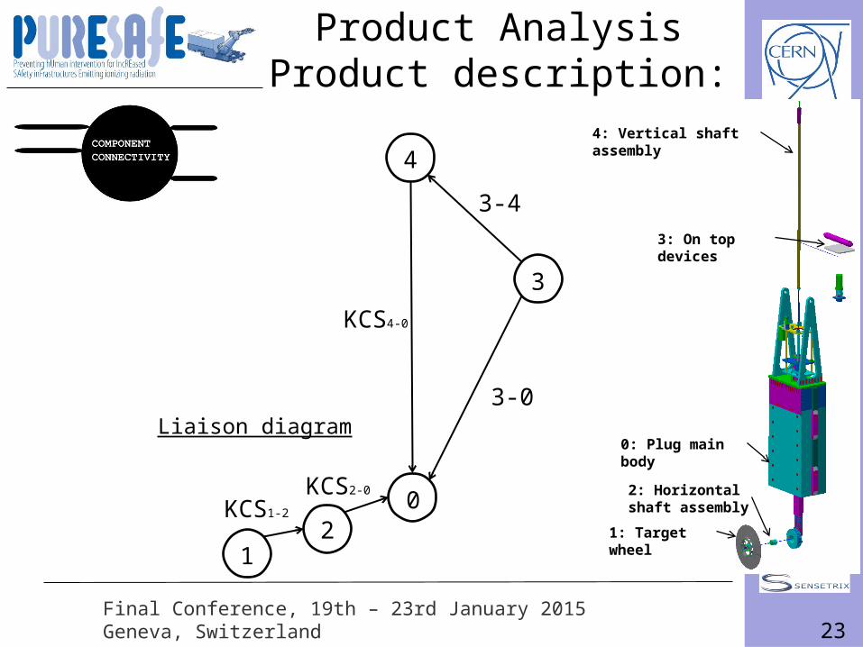
0
4
3
21
KCS1-2
KCS2-0
3-0
KCS4-0
Product AnalysisProduct description:
3-4
4: Vertical shaft assembly
2: Horizontal shaft assembly
1: Target wheel
3: On top devices
0: Plug main body
Liaison diagram
24Final Conference, 19th – 23rd January 2015Geneva, Switzerland
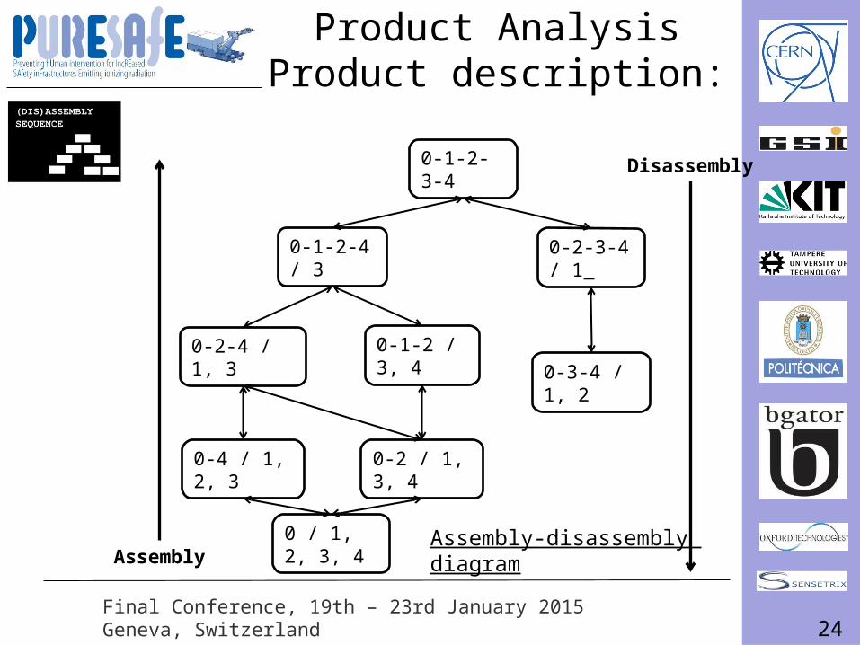
Assembly-disassembly diagram
0-1-2-3-4
0-2-3-4 / 1
0 / 1, 2, 3, 4
0-1-2-4 / 3
0-1-2 / 3, 40-2-4 / 1, 3
0-2 / 1, 3, 40-4 / 1, 2, 3
0-3-4 / 1, 2
Disassembly
Assembly
Product AnalysisProduct description:
25Final Conference, 19th – 23rd January 2015Geneva, Switzerland
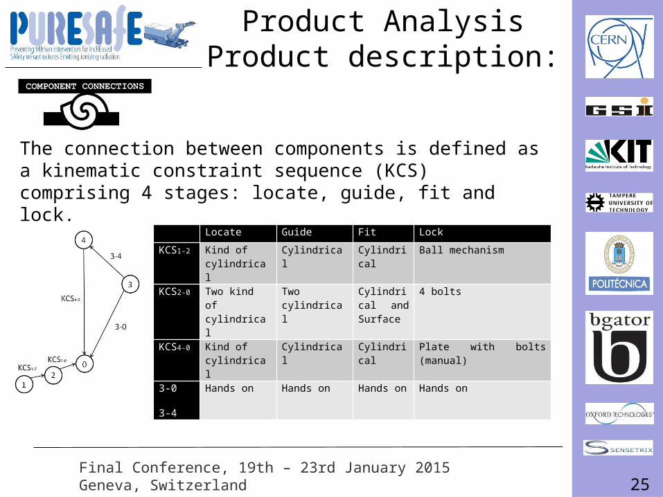
Locate Guide Fit Lock
KCS1-2 Kind of cylindrical
Cylindrical Cylindrical Ball mechanism
KCS2-0 Two kind of cylindrical
Two cylindrical Cylindrical and Surface
4 bolts
KCS4-0 Kind of cylindrical
Cylindrical Cylindrical Plate with bolts (manual)
3-0
3-4
Hands on Hands on Hands on Hands on
The connection between components is defined as a kinematic constraint sequence (KCS) comprising 4 stages: locate, guide, fit and lock.
Product AnalysisProduct description:
26Final Conference, 19th – 23rd January 2015Geneva, Switzerland
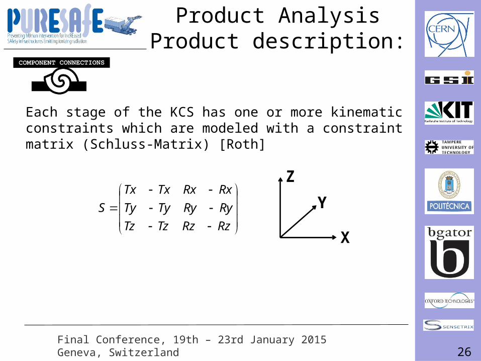
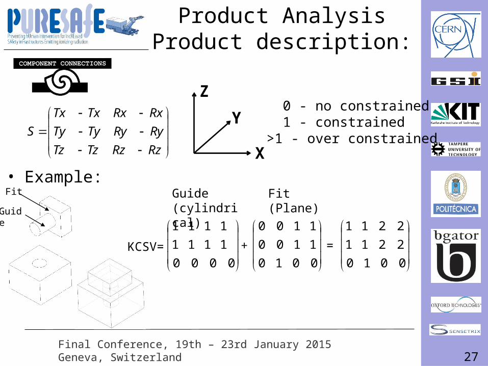
Each stage of the KCS has one or more kinematic constraints which are modeled with a constraint matrix (Schluss-Matrix) [Roth]
Z
Y
X
Product AnalysisProduct description:
RzRzTzTz
RyRyTyTy
RxRxTxTx
S
27Final Conference, 19th – 23rd January 2015Geneva, Switzerland
Z
Y
X
0 - no constrained 1 - constrained>1 - over constrained
Guide(cylindrical)
Fit(Plane)
• Example:
KCSV= + =
Guide
Fit
Product AnalysisProduct description:
RzRzTzTz
RyRyTyTy
RxRxTxTx
S
0000
1111
1111
0010
1100
1100
0010
2211
2211
28Final Conference, 19th – 23rd January 2015Geneva, Switzerland
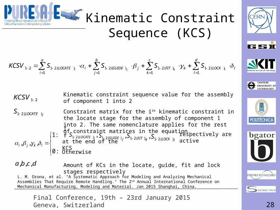
Kinematic Constraint Sequence (KCS)
l
d
lLOCKk
c
kFITj
b
jGUIDEi
a
iLOCATE lkji
SSSSKCSV
1
)(211
)(211
)(211
)(2121
21KCSV
iLOCATES )(21
:0
:1,,, lkji
dcba ,,,
Kinematic constraint sequence value for the assembly of component 1 into 2
Constraint matrix for the ith kinematic constraint in the locate stage for the assembly of component 1 into 2. The same nomenclature applies for the rest of constraint matrices in the equation.
,)(21 jGUIDES ,)(21 kFITS lLOCKS )(21
If
,)(21 iLOCATES respectively are active at the end of the KCS Otherwise
Amount of KCs in the locate, guide, fit and lock stages respectively
L. M. Orona, et al. “A Systematic Approach for Modeling and Analyzing Mechanical Assemblies That Require Remote Handling." The 2nd Annual International Conference on Mechanical Manufacturing, Modeling and Material. Jan 2015 Shanghai, China.
29Final Conference, 19th – 23rd January 2015Geneva, Switzerland
The proposed framework
Replace the horizontal shaft assembly
30Final Conference, 19th – 23rd January 2015Geneva, Switzerland
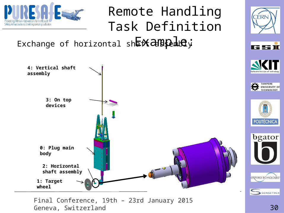
Remote Handling Task Definition Example:
Exchange of horizontal shaft assembly
4: Vertical shaft assembly
2: Horizontal shaft assembly
1: Target wheel
3: On top devices
0: Plug main body
31Final Conference, 19th – 23rd January 2015Geneva, Switzerland
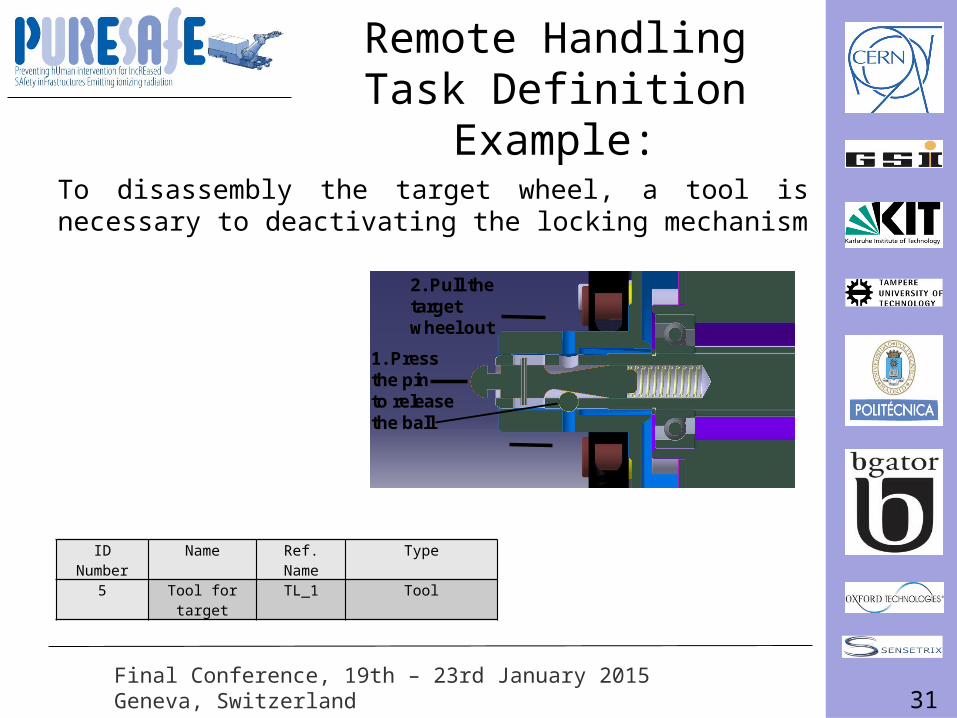
To disassembly the target wheel, a tool is necessary to deactivating the locking mechanism
1. Press the pin to release the ball
2. Pull the target wheel out
ID Number Name Ref. Name Type5 Tool for target TL_1 Tool
Remote Handling Task Definition Example:
32Final Conference, 19th – 23rd January 2015Geneva, Switzerland
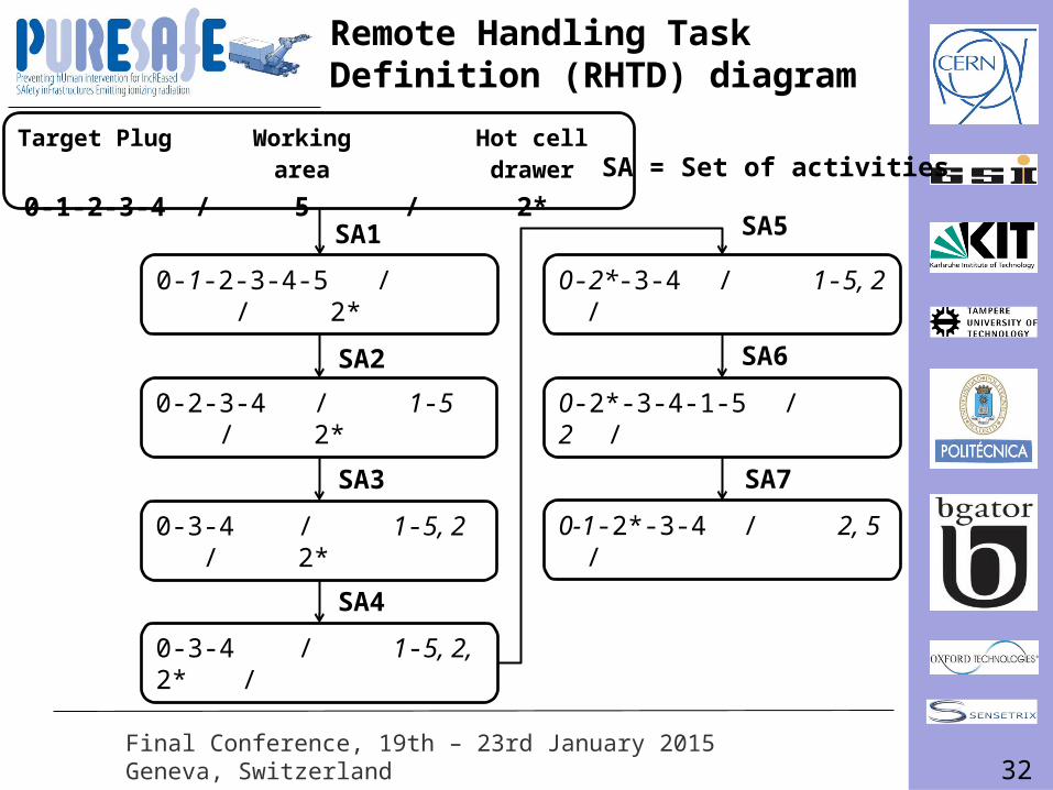
SA1
SA3
SA4
0-2-3-4 / 1-5 / 2*
0-3-4 / 1-5, 2 / 2*
0-3-4 / 1-5, 2, 2* /
SA = Set of activitiesTarget Plug Working area Hot cell drawer
0-1-2-3-4 / 5 / 2*
SA5
0-2*-3-4 / 1-5, 2 /
SA6
0-2*-3-4-1-5 / 2 /
SA7
0-1-2*-3-4 / 2, 5 /
SA2
0-1-2-3-4-5 / / 2*
Remote Handling Task Definition (RHTD) diagram
33Final Conference, 19th – 23rd January 2015Geneva, Switzerland
The proposed framework
Replace the horizontal shaft assembly
34Final Conference, 19th – 23rd January 2015Geneva, Switzerland
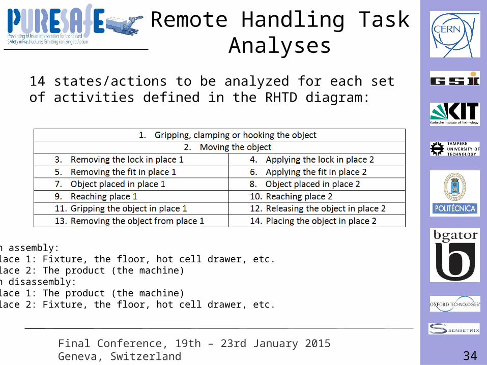
Remote Handling Task Analyses
14 states/actions to be analyzed for each set of activities defined in the RHTD diagram:
In assembly:Place 1: Fixture, the floor, hot cell drawer, etc.Place 2: The product (the machine)In disassembly:Place 1: The product (the machine)Place 2: Fixture, the floor, hot cell drawer, etc.
35Final Conference, 19th – 23rd January 2015Geneva, Switzerland
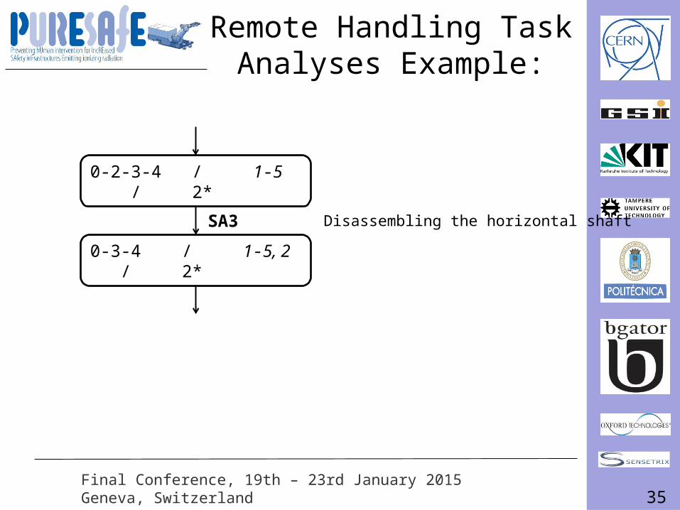
SA3
0-2-3-4 / 1-5 / 2*
0-3-4 / 1-5, 2 / 2*
Disassembling the horizontal shaft
Remote Handling Task Analyses Example:
36Final Conference, 19th – 23rd January 2015Geneva, Switzerland
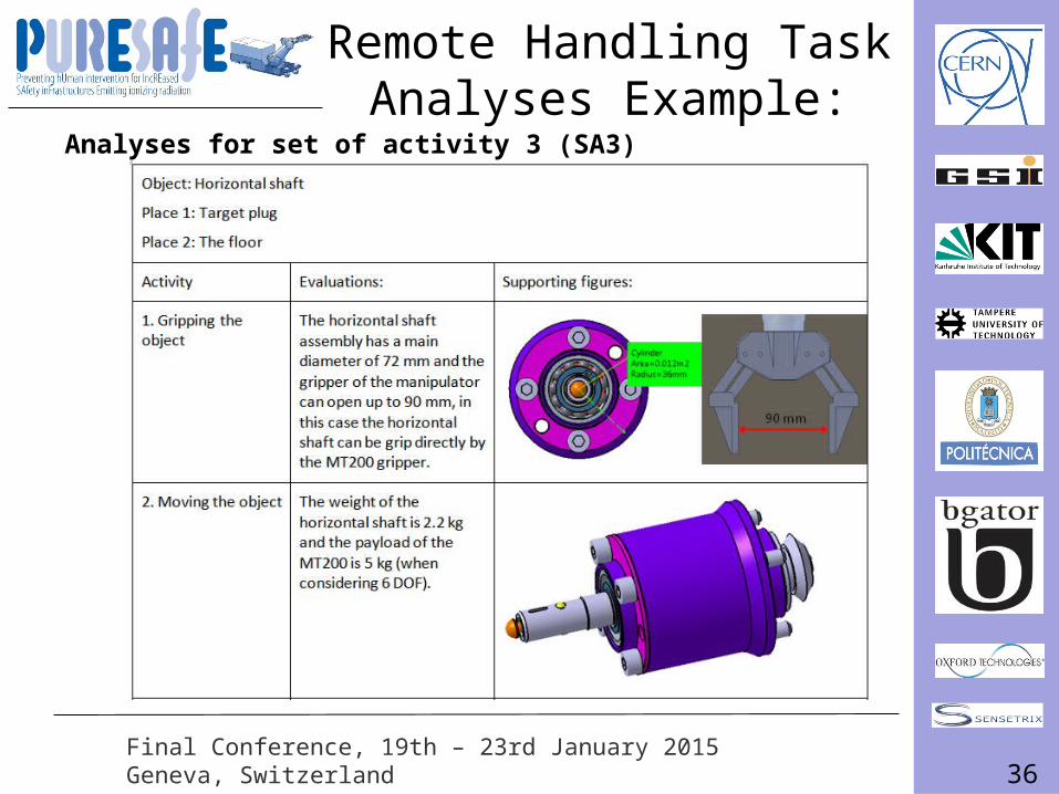
Analyses for set of activity 3 (SA3)
Remote Handling Task Analyses Example:
37Final Conference, 19th – 23rd January 2015Geneva, Switzerland
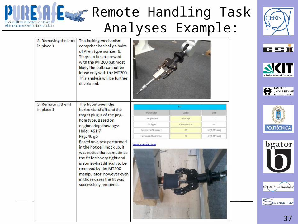
Remote Handling Task Analyses Example:
38Final Conference, 19th – 23rd January 2015Geneva, Switzerland
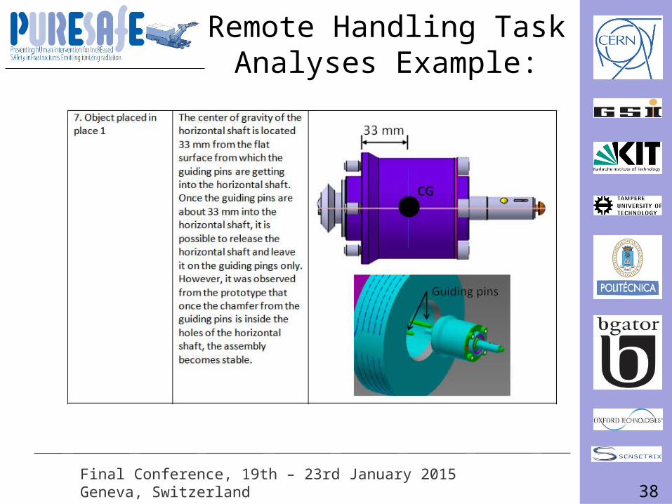
Remote Handling Task Analyses Example:
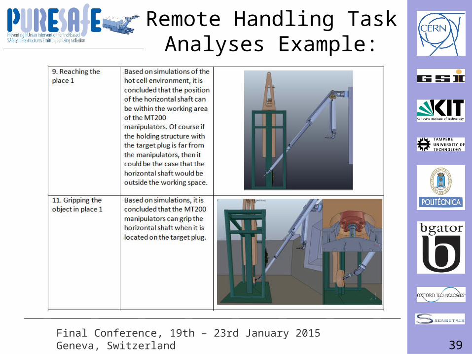
39Final Conference, 19th – 23rd January 2015Geneva, Switzerland
Remote Handling Task Analyses Example:
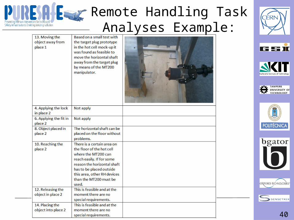
40Final Conference, 19th – 23rd January 2015Geneva, Switzerland
Remote Handling Task Analyses Example:
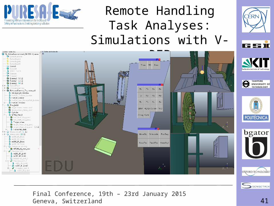
41Final Conference, 19th – 23rd January 2015Geneva, Switzerland
Remote Handling Task Analyses:
Simulations with V-REP
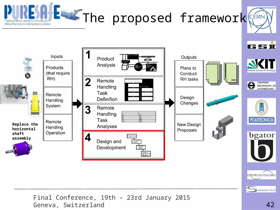
42Final Conference, 19th – 23rd January 2015Geneva, Switzerland
The proposed framework
Replace the horizontal shaft assembly
43Final Conference, 19th – 23rd January 2015Geneva, Switzerland
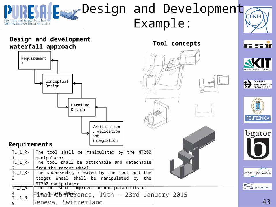
Design and DevelopmentExample:
Requirements
Conceptual Design
Verification, validation and integration
Detailed Design
Tool conceptsDesign and development waterfall approach
TL_1_R-1 The tool shall be manipulated by the MT200 manipulatorTL_1_R-2 The tool shall be attachable and detachable from the target
wheelTL_1_R-3 The subassembly created by the tool and the target wheel
shall be manipulated by the MT200 manipulator TL_1_R-4 The tool shall improve the manipulability of the target wheelTL_1_R-5 …
Requirements
44Final Conference, 19th – 23rd January 2015Geneva, Switzerland
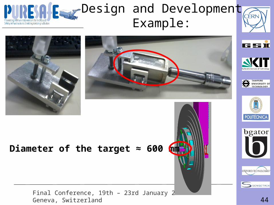
Diameter of the target ≈ 600 mm
Design and DevelopmentExample:
45Final Conference, 19th – 23rd January 2015Geneva, Switzerland
Summary
• Remote handling is required in particle accelerator facilities to conduct maintenance.
• Remote handling is necessary when working environments are inaccessible to humans.
• There is not a unified definition of remote handling.• A framework to define, analyse and develop remote
RH maintenance tasks has been proposed• It is assumed that the proposed framework will
increase our understanding about remote handling.• Developing RH capabilities, is a complex and time
consuming job.
46Final Conference, 19th – 23rd January 2015Geneva, Switzerland
Merci!
Questions and comments