1 first page -...
TRANSCRIPT

Chapter 1
INTRODUCTION
Abstract
This chapter describes the classification and characterisation of composites.
A brief literature survey has been given to have an insight into the current
research works in the subject. Description about green composites and
nanocomposites is made. The scope and major objectives of the present work
have also been highlighted.
Result of this chapter has been communicated for publication in Progress in Polymer Science

2 Chapter 1
1.1 Composites
Developments of more powerful and effective energy sources and maximum
available motive power from them have been a source of constant enquiry.
All technical developments have in fact been centred around these two
vistas. The properties of engineering materials have lent a dependable help in
obtaining motive power from energy sources. For instance, more mechanical
energy is obtained from a gas turbine when the gases stand at a higher
temperature. But the performance of materials in gas turbines is decided by
the maximum workable temperature. There are situations where a suitable
reactor vessel is available in order to with stand the corrosive environment in
the vessel. Many chemical reactions are feasible only then. Many serious
demands of operation or use are successfully met with by seeking
engineering materials. Light weight and stiffness are essential characteristics
for air crafts, aerospace and industries. The structure must be capable to
retain the special properties at high temperature. High strength and corrosion
resistance are unavoidable factors in pressure vessel technology. Weight is
an additional factor to be considered in the case of large pressure vessels. It
is literally impossible for a single material to cater to these requirements at
the same time. When a designer confronts such a problem the best solution is
offered by composite materials.
Composites have gained tremendous industrial importance during the past
few decades and are now considered as engineering materials win an ever-
increasing bonding applications ranging from household articles of everyday
use to supersonic aircrafts and satellites.
During 1896, aeroplane seats and fuel tanks were made of natural fibres with
a small content of polymeric binders. (1). As early as 1908, the first

Introduction 3
composite materials were applied for the fabrication of large quantities of
sheets, tubes and pipes for electronic purposes (paper or cotton to reinforce
sheets, made of phenol or melamine-formaldehyde resins).
Composite materials are engineered materials made from two or more
constituent materials with significantly different physical or chemical
properties which remain separate and distinct on a macroscopic level within
the finished structure. Composites are made up of individual materials
referred to as constituent materials. All the constituents in the composite
retain their identities and do not dissolve or completely merge into each
other. The composite material should be created to obtain properties which
would not be achieved by any of the components acting alone. There are two
categories of constituent materials: The two phases are called matrix and
reinforcement. Matrix is the continuous phase into which the other phase,
often, called the reinforcement or dispersed phase is embedded. The region
between the continuous and dispersed phase is known as the interface. At least
one portion of each type is required. The matrix material surrounds and
supports the reinforcement materials by maintaining their relative positions.
The matrix is the less strong phase being strengthened by the stronger
reinforcing phase. The matrix acts as the bulk material and transfers load
between reinforcement. The reinforcements impart their special mechanical
and physical properties to enhance the matrix properties. A synergism
produces material properties unavailable from the individual constituent
materials, while the wide variety of matrix and strengthening materials
allows the designer of the product or structure to choose an optimum
combination. The matrix also has an additional role, which is to protect the

4 Chapter 1
reinforcement from the environment, abrasion and impact. The matrix has
three main functions.
Functions.
1. To hold the reinforcement in the correct orientation.
2. To protect and reinforcement from damage.
3. To transfer applied loads into the reinforcement.
Reinforcement can have various geometry like particles, fillers, fibres, flakes
or whiskers. The reinforcement provides the strength and stiffness properties
to composite. The form and arrangement of the fillers as they are introduced
to the mould can vary significantly. They can be arranged as short strands of
randomly oriented whiskers, a bundle of fibres, a unidirectional fabric, a
woven fabric, a braid (tubular) fabric or a multi- axial fabric. Reinforcement
may be used in several different forms or arrangements, depending on the
application and manufacturing route. Particles have no preferred directions
and are mainly a means to improve properties or lower cost of isotropic
material. Particles have length to diameter ratios of order unity and dimension
that range from that of a fibre diameter to several millimeters. Whiskers have
length to diameter ratios of order 1000 and diameter of order 0.1-1µm.
Whiskers are pure single crystals manufactured through chemical vapor
deposition and thus have preferred directions. Whiskers are more or less
randomly arranged in the matrix and whisker reinforced composites are likely
to be considered as macroscopically isotropic.
The composites have been classified generally into metal matrix, ceramic
matrix and polymer matrix composites based on the matrix material that
constitutes the composite. Because of the low processing temperature, the

Introduction 5
polymer matrix composites are much easier to fabricate than metal matrix and
ceramic matrix composites. Among the various polymer matrix composites,
fibre reinforced polymer composites have gained much importance in various
fields due to high strength to weight ratio. The most common types of
synthetic fibrous inforcements used in composite applications are glass, carbon
and aramid polyester, nylon and rayon (2-6).
The composites have been classified generally into metal matrix, ceramic
matrix and polymer matrix composites based on the matrix material that
constitutes the composite. Because of the low processing temperature, the
polymer matrix composites are much easier to fabricate than metal matrix and
ceramic matrix composites. Among the various polymer matrix composites,
fibre reinforced polymer composites have gained much importance in various
fields due to high strength to weight ratio. The plant kingdom offers a wealth
of potential resources for composite production. Recently, a large number of
studies have been published in this field (7-11).
1.2 Constituents
The most common types of fibrous reinforcements used in composite
applications are glass, carbon and aramid. Natural fibres have received much
attention from materials scientists and engineers in the past decades because
they are less expensive, lightweight, non-toxicity, ease of recyclability and
biodegradable (12) Light weight materials that involve bio fibre composite
materials are revolutionalising the materials field (13).
1.2.1 Fibres
Plant kingdom contributes profoundly to composite production. In the early
times textiles, ropes, canvas and paper were made of local natural fibres, like
flax and hemp. India continued to use natural fibres, mainly jute fibres as

6 Chapter 1
reinforcements for composites. The growing interest in lignocellulosic fibres
is mainly due to their economical production and also due to the reduction of
the total mass of the composite as a result of the low density of natural fibre.
They also present safer handling and working conditions compared to
synthetic reinforcements. The most interesting aspect about natural fibres is
their positive environmental impact. Biofibres are a renewable resource with
production requiring little energy.
Natural fibres are subdivided based on their origin, coming from plants, animals
or minerals. All vegetable fibres are composed of cellulose whereas fibres of
animal origin consists of proteins(14). low-cost polymeric composites with
reasonable mechanical and tribological properties were successfully developed
using untreated sugarcane fibre (15). Asbestos is an example for mineral fibre.
Plant fibres are composite material designed by the nature. Plant fibres include
bast fibres, leaf fibres, seed/ fruit fibres. Bast consists of a wood core surrounded
by a stem. Within the stem, there are a number of fibre bundles, each containing
individual fibre cells or filaments. Fibres extracted from stems after a process
called retting (16). Examples include flax, hemp, jute, kenaf, and ramie. Leaf
fibres such as sisal, abaca, banana and henequen are coarser than bast fibres.
Cotton is the most common seed fibre. Other examples include coir and oil
palm. Other source of lignocellulosics can be from agricultural residues such as
rice hulls from a rice processing plant, sun flower seed hulls from an oil
processing unit and bagasse from a sugar mill. The properties of natural fibres
vary considerably depending on the fibre diameter, structure, degree of
polymerization, crystal structure and finally whether the fibres are taken from
the plant stem, leaf or seed, and on the growing conditions.

Introduction 7
Jute, sisal, banana and coir (coconut fibre), the major source of natural fibres,
are grown in many parts of India. Some of them have aspect ratios (ratio of
length to diameter) > 1000 and can be woven easily. Sisal and banana fibres
are cellulose-rich (> 65%) and show tensile strength, modulus and failure
strain comparable with other cellulose-rich fibres like jute and flax whereas the
lignin-rich (> 40%) coir fibre is relatively weak and possess high failure strain.
These fibres are extensively used for cordage, sacks, fishnets, matting and
rope, and as filling for mattresses and cushions (e.g. rubberized coir).
Cellulosic fibres are obtained from different parts of plants, e.g. jute and
ramie are obtained from the stem; sisal, banana and pineapple from the leaf;
cotton from the seed; coir from the fruit, and so on.
1.2.1.a Types of natural fibres
Flax:
Flax, Linum usitatissimum, is one of the bast fibres grown chiefly in the
USSR, Poland, France, Belgium and Ireland. The plant cultivated mostly for
its oil-bearing seed (linseed), is also an important source of a vegetable fibre.
Flax plants range in height from 12 to 40 inches, and have shallow taproots.
The same species is used for both fibre and seed, with breeding of
specialized cultivars for the two different products. The seed-producing
varieties have shorter stems and are heavily branched. The fibre varieties
pursue stem development resulting in a taller plant more sparsely branched.
Kenaf:
Kenaf, Hibiscus cannabinus, originating from Africa, has traditionally been a
source of bast fibre in India, China, The Commonwealth of Independent States,

8 Chapter 1
Iran, Nigeria, and Thailand. Kenaf is a newer crop to the United States that shows
good potential as a raw material for use in composite products. Presently, around
4,300 acres of kenaf are cultivated in the United States. 2,000 acres are grown in
Mississippi, 1,200 acres in Texas, 560 acres in California, with lesser amounts in
Louisiana, New Mexico, and Georgia. The plant is a herbaceous annual growing
in single stem to heights of 1 – 4 m. Traditionally, kenaf has been known as a
cordage crop or jute substitute. Research on kenaf first began in the United States
in 1957 and has continued sporadically since that time. Newer advances in
decortications equipment which separates the core from the bast fibre combined
with fibre shortages has renewed recent interest in kenaf as a fibre source.
Hemp:
Hemp fibre is extracted from the plant Cannabis sativa that originated in
Central Asia. From there it spread to China where it is thought to have been
grown for 4,500 years. The plant originally grown for its fibre, came to be
noticed for its narcotic qualities by around 900 BC. Hemp is a strong,
durable, though harsh bast or phloem fibre, having a core, which is
characteristic of hardwood fibre. The bast portion is typically 14%. Hemp is
an annual plant, which at maturity develops a rigid, woody stem ranging in
height from 1.2 - 5 m, and having a diameter from 4 to 20 mm. Generally
hemp is regarded as a tough plant that grows quickly and produces abundant
seed and readily adapts to different niches or areas. Cordage is an area in
which some bast fibres, especially jute, sisal, and hemp, have historically
been strong. Consequently, pultrusion with its use of thread-like material is
especially applicable to these fibres. Cordage machinery having a spectrum
of sophistication and associated processing costs is available to convert these
bast fibre bundles into the appropriate form for such pultrusion products.

Introduction 9
Sisal
This fibre is extracted from the leaves of the plant Agave sisalana which is
widely cultivated in the Western Hemisphere, Africa and Asia. It accounts
for almost half of the total production of all textile fibres. Of the total world
production of 0.6 million tons, India’s share is only 3000 tons. In Kerala,
about 50,000 kg of sisal fibres are extracted every year from the leaves. The
agaves have rosettes of long and narrow fleshy leaves, which grow from a
central bud. As the leaves mature, they gradually spread out horizontally and
are 1-2 m long, 10-15 cm wide and about 6 mm thick at the centre. The
fibres embedded longitudinally in the leaves are most abundant near the leaf
surfaces. Though the leaves contain about 90 % moisture the fleshy pulp is
very firm and the leaves are rigid. Generally by a mechanical decortication
process, i.e, by scrapping away the pulpy material from the leaves the fibre is
removed. In the decortication process, the leaves are fed through sets of
crushing rollers. The crushed leaves are held firmly at their centres and both
ends are passed between pairs of metal drums on which blades are mounted
to scrape away the pulp, and the centers are scraped in the same way. The
fibre strands are then washed and dried.
Coir
Coir is the fibre extracted from the outer husks of coconuts obtained from
coconut tree (Cocos nucifera) and are referred to as 'coco mats' or 'coconut
matting.' The fibres are often obtained by the retting of the outer part of the
fruit followed by drying. More recently with great popularity of natural
flooring it has made its mark as 'Coir carpeting' Coir weaving is a centuries old
craft with the vast majority of the world's production based in the Alleppey
region in Kerala in the south western part of India. Coir products are 100%

10 Chapter 1
natural. Coir carpeting is an 'In-fashion' furnishing accessory, hardwearing,
attractive, warm underfoot, sound insulating, mothproof and rot & fungi
resistant, flame retardant, anti-static, and with regular treatment far more easily
kept clean than its detractors would suggest. Coir pith constitutes about 70 %
of coconut husk with very low density. About 500,000 tons of coconut pith are
produced in India, per annum. Coir fibre is naturally hygroscopic, breathing in
and giving out atmosphere moisture, thus helping to maintain an equable
humidity in the building. This is also the reason why it is always advisable to
fully adhere the material to the sub-floor to avoid stretching or shrinkage. The
coarse structural fibres in coconut fruits, called coir, are composed of vascular
bundles and are similar to the rather stiff, hard fibres obtained from monocot
leaves (manila hemp, sisal, henequen). Because they are tough and naturally
resistant to seawater, coconut fibres are used to make floor mats, heavy cord,
and the coarse nets used in shellfish aquaculture.
Jute
The chief sources of commercial jute are two Indian species (C. capsularis
and C. olitorius), grown primarily in the Ganges and Brahmaputra valleys.
Although jute adapts well to loamy soil in any hot and humid region,
cultivation and harvesting require abundant cheap labour, and India remains
the unrivalled world producer as well as the chief fibre processor. Calcutta is
the main centre. Europe and the United States import large quantities of jute
fibre and clothe; Dundee, Scotland, is also a major jute-textile manufacturer.
The fibre strands in the bark are 6 to 10 ft long (2-3 m) and are separated
from the woody stalk centres by retting. The fibre deteriorates quickly. Due
to its uneven diameter and comparatively low cellulose content, jute fibre is
relatively weak, about 90% is spun into yarn for fabrics; the better qualities

Introduction 11
supply burlap and the poorer grades are used for baling and sacking (e.g.,
gunny sacks). It is also used for twine, rope, carpet, linoleum backing and
insulation. The discarded lower ends, called jute butts, are used for paper
manufacture. This plant, cultivated in India from ancient times, made its
appearance in Western commerce only by about 1830.
Oil palm
Oil palm is one of the most economical and very high potential oil producing
crops. It belongs to the species Elaeis guineensis under the family
Palmaceae, and is commonly found in the tropical forests of West Africa. Its
major industrial cultivation is in the south-east Asian countries such as
Malaysia and Indonesia. Large-scale cultivation has come up in Latin
America. Oil palm cultivation in India has been accelerated with a view to
attain self-sufficiency in oil production. Oil palm empty fruit bunch
(OPEFB) fibre and oil palm mesocarp fibre are two important types of
fibrous materials left in the palm-oil mill. OPEFB is obtained after the
removal of oil seeds from fruit bunch for oil extraction. The average yield of
OPEFB fibre is about 400 g per bunch. The fibres are extracted by retting
followed by cleaning and drying.
Pineapple leaf
The fibres are extracted from the leaves of the plant Ananus comous
belonging to the Bromeliaceae family. They are short-lived perennials or
biennials with a very short main axis and a rosette of leaves. The long,
fleshy, fibrous leaves are sword shaped, dark green and taper to a fine point;
they often have spiny margins. They reach a length of 1 meter or long and
are 5-8 cm wide, grooved on the upper surface and clasps the main axis

12 Chapter 1
closely at the base. These pineapple leaves are a source of very strong
durable fibre. The fibres are shining white when extracted, flexible and is of
good quality.
Banana
Banana fibre, obtained from the pseudo stem of the banana plant, Musa
Sapientum, is another bast fibre. The fibres are extracted either by retting or by
scraping the pithy material with a wooden scraper. The fibres are then washed in
water and hung in the shade to dry. Fibres can be extracted before or after
harvesting the fruit. But, the fibres obtained after harvesting the fruit have better
properties compared to the ones obtained before harvesting. The fibre property
also varies depending on the season and the region in which the plants grow. In
India, approaximately 1.5 million acres of land is for under banana plantation, and
this yields about 3x10⁵ tons of fibre. In Kerala, about 5 lakh acres of land is under
banana cultivation. Normally 600 trees are grown in an acre of land. A stem
weighing about 37 kg yields about 1 kg of good quality fibre as a by product.
Recent reports indicate that plant-based natural fibres can very well be used
as reinforcement in polymer composites, replacing to some extent more
expensive and non-renewable synthetic fibres such as glass (17, 18). Gastón
et al. (19) attempted to understand how the main processing variables are
affected when glass fibres are replaced by natural fibres in reinforced
plastics. In this publication, a jute fabric was characterised in terms of its
saturated and unsaturated permeability. Oaksman (20) found that fluid
absorption and swelling are mechanisms present in natural fibres that reduce
both permeabilities. Fluid absorption removes fluid from the main stream as
it travels through the reinforcement, acting as a sink component and thus

Introduction 13
decreasing flow velocity during the unsaturated flow. Also, the saturation of
the natural fibres cause swelling, reducing the porosity and increasing flow
resistance during saturated flow.
There are many examples of the use of cellulosic fibres in their native
condition like sisal, coir, jute, banana, palm, flax, cotton, and paper for
reinforcement of different thermoplastic and thermosetting materials like
phenol formaldehyde, unsaturated polyester, epoxy, polyethylene, cement,
natural rubber etc.
Different geometries of these fibres, both singly and in combination with
glass, have been employed for fabrication of uni-axial, bi-axial and randomly
oriented composites. Amongst these ligno-cellulosic fibres, jute contains a
fairly high proportion of stiff natural cellulose.
Retted fibres of jute have three principal chemical constituents, namely, α-
cellulose, hemicellulose and lignin. In addition, they contain minor
constituents such as fats and waxes, inorganic (mineral) matter, nitrogenous
matter and traces of pigments like β-carotene and xanthophyll.
Several studies of fibre composition and morphology have found that
cellulose content and microfibril angle tend to control the mechanical
properties of cellulosic fibres. Higher cellulose content and lower microfibril
angle result in higher work of fracture in impact testing.
Sisal and banana fibres show better reinforcing efficiency than coir and the
specific strength properties of the composites are comparable to those of
glass fibre reinforced plastics (GRP). On the other hand, coir fibre, despite
having low strength and modulus, improves the impact resistance of
polyester due to its large strain energy absorption.

14 Chapter 1
Although the tensile strength and Young’s modulus of jute are lower than
those of glass fibres, the specific modulus of jute fibre is superior to that of
glass and when compared on modulus per cost basis, jute is far superior. The
specific strength per unit cost of jute, too, approaches that of glass.
Therefore, where high strength is not a priority, jute may be used to fully or
partially replace glass fibre. The need for using jute fibres in place of the
traditional glass fibre partly or fully as reinforcing agents in composites
stems from its lower specific gravity (1.29) and higher specific modulus (40
GPa) of jute compared with those of glass (2.5 & 30 GPa respectively).
Apart from much lower cost and renewable nature of jute, much lower
energy requirement for the production of jute (only 2% of that for glass)
makes it attractive as a reinforcing fibre in composites.
Lignocellulosic fibres offer many advantages that make them more attractive as
fillers and reinforcements for plastics. These advantages include low density,
low cost, less abrasiveness, higher specific properties, toxinless, easiness to
handle, no health problems like glass fibre which can cause skin irritations
during processing and respiratory diseases when the fibrous dust is inhailed (21).
There are also some environmental and socio-economic advantages that cannot
be ignored. These include biodegradability, the wide variety of fibres available
around the world, the generation of rural jobs, stimulation of non-food
agricultural/farm based economy, low energy consumption, and low energy of
utilization. Despite the advantages mentioned above, the fibres exhibit some
undesirable characteristics, which result in inferior composite properties. These
include the thermal instability above 200oC and high moisture absorption which
can affect both dimensional stability and mechanical properties of the
composite. The hydrophilic nature of lignocellulosic fibres is also responsible

Introduction 15
for insufficient fibre dispersion, poor fibre/matrix compatibility and interfacial
adhesion of the fibres with some hydrophobic thermoplastic matrices. Their low
microbial resistance and susceptibility to rotting limits the service life of
lignocellulosic/thermoplastic composites particularly for outdoor applications
(22). In addition to the above, lignocellulosic fibres also exhibit non uniformity
and variability of their dimensions as well as mechanical properties. However,
natural fibres are undergoing high tech revolution in replacing synthetic
materials from housing to clothing, touching every aspect of our lives. Pipes,
pultruded profiles and panels with polyester matrices were produced with
these fibres (23).
The development of commercially viable “green products” based on natural
resources for both matrices and reinforcements for a wide range of
applications is on the rise. This effort includes new pathways to produce
natural polymers with better mechanical properties and thermal stability
using nanotechnology and use of natural polymers to make biodegradable
plastics and their composites with lignocellulosic fibres (24-30).
1.2.2 Chemical composition of lignocellulosic fibre
The chemical composition and structure of plant fibres depend to a large
extent on the climatic conditions, age and the digestion process of the plant,
which they are derived from. The wt % value of each components in some
plant fibres are presented in table 1.1 (31-32)

16 Chapter 1
Table 1.1 Composition of some plant fibres
Component
Plant fibres
Cotton Jute Flax Hemp Coir Ramie Pine- apple
leaf Banana
Cellulose (wt%) 82.7 61-71.5 64.1-71 70.2-74.4 36-43 68.6- 76.2 70 - 82 63 - 64
Hemicellulose
(wt%) 5.7 13.6- 20.4 16.7- 20.6 17.9-22.4 0.15-0.25 13.1- 16.7 - 19
Pectin (wt%) 5.7 0.2 1.8 - 2.3 0.9 3-4 1.9 - -
Lignin (wt%) - 12 - 13 1.7 - 2.0 3.7- 5.7 41 - 45 0.6-0.7 5-12 5
Waxes (wt%) 0.6 0.5 1.5 - 1.7 0.8 - 0.3 - -
Moisture content(%)
10 10-12.6 10 10.8 8 8 11.8 10 -12
Microfibril angle(%) 8 10 6.2 20.0 41 - 45 7.5 14.0 11
[Reference: J. G.Cook, Handbook of Textile Fibre and Natural Fibres, 4th Ed., Morrow Publishing, England, 1968]
The physical properties of fibres mainly depend on cellulose (content and
orientation of molecules) hemi cellulose and lignin. Hemicelluloses and
pectin are responsible for the bio-degradation, moisture absorption and
thermal degradation of fibre. Individual fibre properties and the structure of
fibre can vary widely depending upon the plant, part of the stem, age,
extraction technique, moisture content etc.
The major component of most plant fibres is cellulose (α-cellulose). Cellulose
is a linear macromolecule consisting of D-anhydroglucose repeating units
joined by β-1, 4-glycosidic linkages with a degree of polymerization (DP) of
around 10,000 (8). Each repeating unit contains three hydroxyl groups. These

Introduction 17
hydroxyl groups and their ability to hydrogen bond play a major role in
directing the crystalline packing and also govern the physical properties of
cellulose materials (8). A single or elementary plant fibre is a single cell
typically of a length from 1to 50 mm and a diameter of around 10-50 µm.
Plant fibres are like microscopic tubes i.e. cell walls surrounding the central
lumen. The lumen contributes to the water uptake behavior of plant fibres (33).
The fibre consists of several cell walls. These cell walls are formed from
oriented reinforcing semicrystalline cellulose microfibrils embedded in a
hemicellulose-lignin matrix of varying composition. Such microfibrils have
typically a diameter of about 10-30 nm, and are made up of 30-100 cellulose
molecules in extended chain conformation and provide mechanical strength to
the fibre. Fig. 1.1 shows the arrangement of fibrils, microfibrils and cellulose
in the cell walls of a plant fibre.
Figure 1.1 Arrangement of fibrils, microfibrils and cellulose in the cell walls
(Ref: Ph.D Thesis of Shirly Annie Paul, Mahatma Gandhi University, India, 2008)

18 Chapter 1
Cellulose
The molecular structure of cellulose, which is responsible for its
supramolecular structure determines many of its chemical and physical
properties. In the fully extended molecule, the adjacent chain units are
oriented by their mean planes at the angle of 1800 to each other. Thus, the
repeating unit in cellulose is the anhydrocellulobiose unit and the number of
repeating units per molecule is half the DP. This may be as high as 14000 in
native cellulose. The structure of cellulose is given figure 1.2.
Figure 1.2. Structure of cellulose
(Reference: A.K.Bledzki, J.Gassan, Prog. Polym. Sci., 24, 221, 1999)
As the mechanical properties of natural fibres depend on the cellulose type,
each type of cellulose has its own cell geometry and the geometrical
conditions determine the mechanical properties. Solid cellulose forms a
microcrystalline structure with regions of high order i.e. crystalline
regions and regions of low order i.e. amorphous regions. Cellulose is also
formed of slender rod like crystalline microfibrils. The crystal nature
(monoclinic sphenodic) of naturally occurring cellulose is known as
cellulose I. Cellulose is resistant to strong alkali (17.5 wt%) but is easily
hydrolyzed by acid to water-soluble sugars. Cellulose is relatively
resistant to oxidizing agents.

Introduction 19
Hemicellulose
Hemicellulose is not a form of cellulose at all. It comprises a group of
polysaccharides (excluding pectin) that remains associated with the cellulose
after lignin has been removed. The hemicellulose differs from cellulose in
three important aspects. In the first place they contain several different sugar
units whereas cellulose contains only 1,4-β-D-glucopyranose units. Secondly
they exhibit a considerable degree of chain branching, where as cellulose is
strictly a linear polymer.
Thirdly, the degree of polymerization of native cellulose is ten to one
hundred times higher than that of hemicellulose. Unlike cellulose, the
constituents of hemicellulose differ from plant to plant (34). Figure 1.3
depicts the structure of hemicellulose.
Figure 1.3 Structure of hemicellulose
(Reference: A.K Bledzki, J.Gassan, Prog. Polym. Sci., 24, 221, 1999)
Lignins
Lignins are complex hydrocarbon polymers with both aliphatic and aromatic
constituents. (35).
Their chief monomer units are various ring-substituted phenyl propanes
linked together in ways, which are still not fully understood. The mechanical
properties are lower than those of cellulose (36).

20 Chapter 1
Figure 1.4 Structure of lignin
(Reference: A.K Bledzki, J.Gassan, Prog. Polym. Sci., 24, 221, 1999)
Lignin is totally amorphous and hydrophobic in nature. It is the
compound that gives rigidity to the plants. Lignin is considered to be a
thermoplastic polymer exhibiting a glass transition temperature of around
90°C and melting temperature of around 170°C (37).
It is not hydrolyzed by acids, but soluble in hot alkali, readily oxidized
and easily condensable with phenol (35). The structure is presented in
figure 1.4.
Pectins and waxes
Pectin is a collective name for heteropolysaccharides, which consist
essentially of polygalacturon acid. Pectin is soluble in water only after a
partial neutralisation with alkali or ammonium hydroxide. It provides
flexibility to plants. Waxes make up the last part of fibres and they consist
of different types of alcohols, which are insoluble in water as well as in
several acids.
Introduction 21
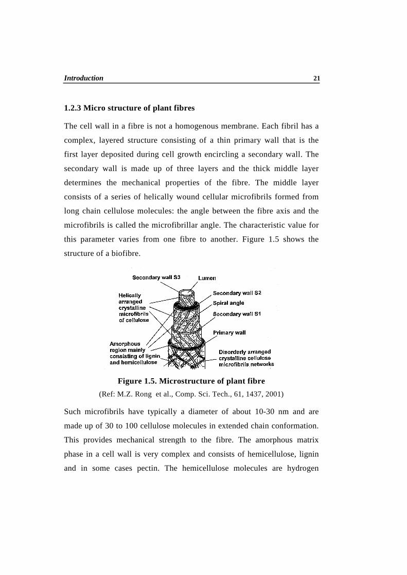
1.2.3 Micro structure of plant fibres
The cell wall in a fibre is not a homogenous membrane. Each fibril has a
complex, layered structure consisting of a thin primary wall that is the
first layer deposited during cell growth encircling a secondary wall. The
secondary wall is made up of three layers and the thick middle layer
determines the mechanical properties of the fibre. The middle layer
consists of a series of helically wound cellular microfibrils formed from
long chain cellulose molecules: the angle between the fibre axis and the
microfibrils is called the microfibrillar angle. The characteristic value for
this parameter varies from one fibre to another. Figure 1.5 shows the
structure of a biofibre.
Figure 1.5. Microstructure of plant fibre
(Ref: M.Z. Rong et al., Comp. Sci. Tech., 61, 1437, 2001)
Such microfibrils have typically a diameter of about 10-30 nm and are
made up of 30 to 100 cellulose molecules in extended chain conformation.
This provides mechanical strength to the fibre. The amorphous matrix
phase in a cell wall is very complex and consists of hemicellulose, lignin
and in some cases pectin. The hemicellulose molecules are hydrogen

22 Chapter 1
bonded to cellulose and act as cementing matrix between the cellulose
microfibrils, forming the cellulose-hemicellulose network, which is thought
to be the main structural component of the fibre cell. The hydrophobic lignin
network affects the properties of other network in a way that it acts as a
coupling agent and increases the stiffness of the cellulose/ hemicellulose
composite.
The structure, microfibrillar angle, cell dimensions, defects and the
chemical composition of fibres are the most important variables that
determine the overall properties of the fibres (38).
The microfibrillar angle, cellulose content and moisture content determine
the mechanical properties of the cellulose based natural fibres (39).
Generally, tensile strength and Young’s modulus of fibres increase with
increasing cellulose content. The microfibrillar angle determines the stiffness
of the fibres. Plant fibres are more ductile if the microfibrils have a spiral
orientation to the fibre axis. If the microfibrils are oriented parallel to the
fibre axis, the fibres will be rigid, inflexible and have high tensile
strength.When the specific modulus of natural fibres is considered, they
show comparable or better value than those of glass fibres (40).
Unlike man-made synthetic fibres, natural fibres, extracted from plants have
various geometry. The fibre length and diameter are main parameters, which
have certain influence on the reinforcing capabilities in composites. This
geometrical pattern of the extracted fibres varies not only from one plant to
another but vary from one part of the palnt to other. Table 1.2 gives an idea
on the structural parameters of different cellulosic fibres (41).

Introduction 23
Table 1.2. Structural parameters of different fibres
Fibre Spiral Angle(θo)
Cross sectional area Ax10-2
(mm2)
Cell-length L(mm)
L/D ratio (D is the cell diameter)
Jute 8 0.12 2.3 110
Flax 10 0.12 20 1687
Hemp 6.2 0.06 23 960
Ramie 7.5 0.03 124 3500
Sisal 20 1.10 2.2 100
Coir 45 1.20 3.3 35
(E. T. N. Bisanda, M. P. Ansell, J. Mater. Sci., 27, 1690-1700, (1992)
Mechanical properties of natural fibres, like geometrical properties, vary to a
large extent. Natural fibres exhibit considerable variation in diameter along
with the individual bundles. Quality as well as most of their properties
depend on the factors like size, maturity as well as the processing methods
adopted for the extraction of fibres. Properties such as tensile strength,
modulus etc. strongly depend on the internal structure and chemical
composition of fibres. Table 1.3 gives us a comparison regarding the
mechanical properties of natural fibres and synthetic fibres (30).

24 Chapter 1
Table 1.3. Mechanical properties of natural fibres as compared to various synthetic fibres
Fibre Density (g/cm3)
Elongation (%)
Tensile strength (MPa)
Young’s modulus (GPa)
Cotton 1.5-1.6 7.0-8.0 287-597 5.5-12.6
Jute 1.3 1.5-1.8 393-773 26.5
Flax 1.5 2.7-3.2 345-1035 27.6
Hemp - 1.6 690 -
Ramie - 3.6-3.8 400-938 61.4-128
Sisal 1.5 2.0-2.5 511-635 9.4-22.0
Coir 1.2 30.0 175 4.0-6.0
Viscose - 11.4 593 11.0
Soft wood kraft
1.5 - 1000 40.0
E glass 2.5 2.5 2000-3500 70.0
S-glass 2.5 2.8 4570 86.0
Aramid
(Normal)
1.4 3.3-3.7 3000-3150 63.0-67.0
Carbon
(Standard)
1.4 1.4-1.8 4000 230.0-240.0
(Ref: AK Bledzki, S Reihmane, J Gassan, J Appl Polym Sci, 29, 1329, (1996)
1.2.4 Thermal stability of natural fibres
Thermogravimetry is one of the most widely used techniques to monitor the
composition and structural dependence on the thermal degradation of natural
cellulose fibre. This is because the different compositions and supramolecular
structures of cellulose behave differently when undergoing thermal
degradation. Natural fibre is composed mainly of cellulose, hemicelluloses and

Introduction 25
lignin. Each of the three major components has its own characteristic
properties with respect to thermal degradation, which are based on polymer
composition. However, the microstructure and three-dimensional nature of
natural fibre are variables that also play important roles in terms of their
effects on combustion behavior. Thus, the individual chemical components of
fibre behave differently if they are isolated or if they are intimately combined
within each single cell of the fibre structure (42).
Lignin, specifically the low molecular weight protolignin, degrades first and
at a slower rate than the other constituents.
1.2.5 Advantages and disadvantages of plant fibres
Plant fibres are advantageous to synthetic fibres due to the following reasons
(45). These fibres are mainly based on cellulose, which is the most abundant
material on our planet and so are inexpensive. They are produced to the
extent of about 4.4 x 10¹⁴ kg annually by plants and are renewable. The
growing interest in lignocellulosic fibres is mainly due to their economical
production with few requirements for equipment and low specific weight,
which results in a higher specific strength and stiffness when compared to
glass reinforced composites. They are carbon dioxide neutral i.e. they do not
return excess carbon dioxide into the atmosphere when they are composted
or subjected to combustion. They are amenable to physical, chemical and
mechanical modifications. They possess high flexibility and their breaking
resistance is high. Hence they undergo bending rather than breakage unlike
synthetic fibres (44).
The chemical structure includes rigid cellulose fibres immersed in soft lignin
matrix. Rigid cellulose possesses very high modulus of rigidity among

26 Chapter 1
polymers. Their rough surfaces lead to mechanical anchorage and this
increases fibre-matrix adhesion. Plant fibres are nonabrasive to mixing and
moulding equipment, which can contribute to significant cost reductions. The
most interesting aspect about natural fibres is their positive environmental
impact and they cause no health hazards. They are susceptible to microbial
decomposition, including mildew, aerobic bacteria, fungi, moths, carpet
beetles, termites and rot. Hence these are biodegradable. Biofibres possess
high electrical resistance. Thermal recycling is also possible. The hollow
cellular structure provides good acoustic insulating properties. With the
exception of mineral fibres, all natural fibres have an affinity for water. This
strong affinity results in the swelling of the fibres, which facilitates dyeing in
watery solutions.
Although plant fibres have several advantages over synthetic fibres they have
some disadvantages resulting from their chemical composition and structure.
There is a major drawback associated with the application of natural fibres
for reinforcement of resin matrices. Due to presence of hydroxy and other
polar groups in various constituents of natural fibre, the moisture uptake is
high (approx. 12.5% at 65% relative humidity & 20oC) by dry fibre. All this
leads to:
• poor wettability with resin and
• weak interfacial bonding between the fibre and relatively more
hydrophobic matrices.
Environmental performance of such composites is generally poor due to
delamination under humid conditions. With increase in relative humidity up
to 70%, the tenacity and Young’s modulus of jute increases but beyond 70%,

Introduction 27
a decrease is observed. Thus, it is essential to pre-treat the fibre so that its
moisture absorption is reduced and the wettability by the resin is improved.
1.2.6 Modification of natural fibre
In order to develop composites with better mechanical properties and
environmental performance, it is necessary to impart hydrophobicity to the
natural fibres by chemical reaction with suitable coupling agents or by
coating with appropriate resins.
Such surface modification of fibre does not only decrease moisture
adsorption, but also concomitantly increases wettability of fibres with resin
and improve the interfacial bond strength, which are critical factors for
obtaining better mechanical properties of composites.
Modification of jute and other natural cellulosic fibres can be done by
following means:
• Chemical means
• Coating with polymeric solutions and
• Graft co-polymerization.
Natural fibre is chemically treated with isopropyl triisostearoyl titanate
(abbreviated as titanate), γ -aminopropyl trimethoxy silane (abbreviated as
silane), sebacoyl chloride (SC), and toluene di-isocynate (TDI). All these
reagents are expected to block the hydroxy groups of jute thus making the fibres
more hydrophobic. These surface modifiers penetrate and deposit into lumens of
cell wall of fibre, minimizing the possible extent of moisture ingress.
Polymeric coating of natural fibre with phenol-formaldehyde or resorcinol
formaldehyde resins by different approaches are highly effective in enhancing

28 Chapter 1
the reinforcing character, giving as high as 20-40% improvement in flexural
strength and 40-60% improvement in flexural modulus. These modifications
improve the fibre-resin wettability and lead to enhanced bonding.
Natural fibre such as jute can be graft co-polymerized with vinyl monomers
such as methyl methacrylate, ethyl acrylate, styrene, vinyl acetate,
acrylonitrile & acrylamide in presence of different redox initiator systems
such as vanadium-cyclohexanol, vanadium-cyclohexanone etc.
Grafting of poly-acrylonitrile (10-25%) imparts 10-30% improvement in
flexural strength and flexural modulus of the composites. Grafting of
polymethylmethacrylate is also effective in this respect, though to a lower
degree.
1.3 Matrix
The constituent that is continuous and is often (but not always) present in
greater quantity is termed as matrix. Matrix provides toughness and ductility
to the composite. They have a strong influence on several mechanical
properties of the composite such as transverse modulus and strength, shear
properties and properties of compression. They also bind the dispersion
phase together and cause them to act as a team in resisting failure or
deformation under an applied load. The main role of the matrix is to transmit
and distribute stresses along the reinforcement phase. Physical and chemical
characteristics of the matrix such as melting or curing temperature, viscosity,
and reactivity with fibres influence the choice of fabrication process.
Commonly used matrix materials include polymers, metals, and ceramics.

Introduction 29
1.3.1. Polymers
Polymers are the most widely used matrix materials for fibre composites.
Their chief advantages are low cost, easy processability, good chemical
resistance and low specific gravity. On the other hand, low strength, low
modulus and low operating temperatures limit their use. They are also
degraded by prolonged exposure to ultraviolet light as well as some solvents.
1.3.1.1. Thermosetting, thermoplastic and rubbery polymers
Based on their structure and behaviour, polymers can be classified as
thermoplastics or thermosets. The thermoplastics are incorporated into the
composite system by melting and then they are solidified by cooling; the
physical reaction being reversible in nature. It consists of linear or branched-
chain molecules having strong intramolecular bonds but weak intermolecular
bonds. They can be reshaped by application of heat and pressure and are
either semicrystalline or amorphous in structure. Examples include
polyethylene, polystyrene, nylons, polycarbonate, polyacetals, polyamide-
imide, polyether-ether ketone, and polysulfone polyphenylene sulfide and
polyether imide. Thermosetting plastics have crosslinked or network
structures with covalent bonds between all molecules. They do not soften but
decompose on heating. Once solidified by cross-linking process, they cannot
be reshaped. Common examples of thermosetting polymers include epoxies,
polyesters, phenolics, ureas, melamine, silicone and polyimides.
Rubber is a unique engineering material because unlike other engineering
solids, it has high elastic deformability and an almost theoretical value for
poison’s ratio (0.5). It is currently used in bridge bearings, medical devices,
springs, anti vibration mountings to prevent earthquakes and other
30 Chapter 1
suspension systems. Polymerisation of rubber yields highly branched
polymers. Branching supports good tack and a strong bond in adhesive
applications. The physically entangled structure of this kind of polymer also
provides a significant improvement in tear strength. The natural resistance to
flow makes them excellent candidates for compression molding and
sponge.Other applications are thin walled or complex extrusions where shape
retention is important.
1.3.1.2 Elastomers
Elastomers are amorphous polymers existing above their glass transition
temperature, so that considerable segmental motion is possible. At ambient
temperatures, rubbers are thus relatively soft and deformable. Their primary
uses are for seals, adhesives and molded flexible parts. Natural rubber (NR)
is an elastomer (an elastic hydrocarbon polymer) that was originally derived
from a milky colloidal suspension, or latex, found in the sap of some plants.
Natural rubber is a unique biomass. It is the only one polymeric hydrocarbon
among many biopolymers whose source is almost Hevea brasiliensis. NR is
an indispensable material for many industrial and household applications,1
which is constituted of cis-1,4-polyisoprene (ca. 94%) and non-rubber
components such as proteins (ca. 2%) and lipid (ca. 3%). The versatility of
the plant-derived NR is mainly due to its outstanding tensile properties and
the good crack growth resistance.
Crude rubber is a tough and an elastic solid. It becomes soft and sticky as the
temperature rises. The purified form of natural rubber is the chemical
polyisoprene which can also be produced synthetically. The structure of
natural rubber is given below.

Introduction 31
There may be as many as 11,000 to 20,000 isoprene units in a polymer chain
of natural rubber. Its specific gravity is ~0.915. Natural rubber has a broad
bimodal molecular weight distribution. The polydispersity or the ratio of
weight-average molecular weight to number-average molecular weight,
Mw/Mn, can be as high 9.0 for some variety of natural rubber. Natural rubber
is used extensively in many applications and products as is synthetic rubber.
The use of natural rubber (NR) is widespread in everyday life through many
household or industrial applications, thanks to its outstanding physical
properties such as high stress at break and good crack growth resistance.
1.3.1.3. Polyester resin
The workhorse of thermoset matrices is unsaturated polyester, which offers an
attractive combination of low price, reasonably good properties and
uncomplicated processing. A polyester resin is unsaturated (reactive) polyester
solid dissolved in a polymerizable monomer. Unsaturated polyesters are long
chain linear polymers containing a number of carbon double bonds. They are
made by a condensation reaction between a glycol and an unsaturated dibasic
acid (maleic or fumaric). The polymerizable monomer such as styrene which
also contains carbon double bonds, act as cross linking agent by bridging
adjacent polyester molecules at their unsaturation points. The monomer also acts
as a diluent, reduces viscosity, and makes it easier to process. The curing or
cross linking process is initiated by adding a small quantity of a catalyst like
organic peroxide or an aliphatic azo compound. Since there is no by-product of
the reaction, the curing is done at room temperature or elevated temperature

32 Chapter 1
with or without application of pressure. The structure of typical polyester made
from maleic acid and diethylene glycol is shown below.
HOC
OCH CH C
O
OH+ HOCH2CH2OCH2CH2OH
HO CH2CH2OCH2CH2OC CH CHC O n
O O
H2O+H
(Ref: B.D.Agarwal., L.J Broutman. Analysis and Performance of Fibre Composites, John Wiley and Sons. Inc. 1990 )
The length of the molecule or degree of polymerization may vary. The resin
will generally be a solid but is dissolved in a monomer such as styrene. The
solution viscosity can be controlled by the percentage of styrene. The
conversion from liquid to solid occurs through the use of a free radical
initiator or curing agent. The styrene monomer cross-links react with the
double bond in the polyester backbone above to form a network polymer as
indicted below.
CCOO OOCC CCOO OOCC CCOO OOCCOOCCR CCOO
CCOO OOCC CCOO OOCC CCOO OOCCOOCCR CCOO
(St) (St) (St) (St)
(St)(St)(St)(St)
(St) (St) (St) (St)
CH2 CH
St = Styrene link

Introduction 33
1.3.1.4 Epoxy resin
Epoxies are generally seen in fields where the cost tolerance is the highest,
eg. aerospace, defense and sports applications. Epoxy resins are low
molecular weight organic liquids containing a number of epoxide groups,
which are three-membered rings with one oxygen and two carbon atoms. The
most common process for producing epoxies is the reaction of
epichlorohydrin with bisphenol-A amino or acid compounds, and cross-
linking is obtained by introducing chemicals that react with the epoxy and
hydroxy groups between the adjacent chains. The chemical reaction to form
epoxy resin pre-polymer is as shown below.
CH2 CHCH2Cl + OHO
2 HO C
CH3
CH3
CH2 CHCH2O O
OCH2CH2CH CH2+ 2HCl
OC
CH3
CH3
Epoxy systems, like polyesters, can be cured at room temperature, but quite
often heat is added to accelerate and improve curing. The choice of curing
agent dictates whether a room temperature or elevated temperature cure is
required.
1.3.1.5 Phenolic resin
Phenolic resins have been in commercial use longer than any other synthetic
polymer except cellulose nitrate. In contrast to the latter, however, the sales
of phenolic resins continued to rise at about 15% per year, reaching a peak of
about 1.3 billion-lb in 1979. Phenols react with aldehydes to give

34 Chapter 1
condensation products if there are free positions on the benzene ring ortho
and para to the hydroxyl group. Formaldehyde is by far the most reactive
aldehyde and is used almost exclusively in commercial production. By far
the largest use of the phenolics is in heat-setting adhesives for plywood.
Generally the interaction of cellulose fibre with PF resin is splendid due to
the hydrophilic nature of cellulose and PF resin. This is shown schematically
in Fig. 1.6.
Jackson et al. (45) investigated the toughening of phenolic thermoset and its
composites reinforced with sisal fibres, using hydroxyl-terminated
polybutadiene rubber (HTPB) as both impact modifier and coupling agent.
Substantial increase in the impact strength of the thermoset was achieved by
the addition 10% of HTPB.
Figure 1.6 Schematic representation of interaction of cellulose fibre with PF resin (Ref: B. M. Cherian, Unpublished Work)
H2C
CH2
O
CH2
CH2
O
CH2
CH2
O
CH2
o
O
O
CH2OH o
O
O
CH2OH
O
o
O
CH2OH
o
O
O
HOH2Co
O
O
HOH2C
Oo
O
HOH2C
H2C
CH2
HO
CH2
CH2
CH2
H2C
CH2
Cured Composite
o
HO OH
O
HOH2C
CH2 O
H OH
CH2
O
H
CH2 O H
o
OHHO
O
CH2OH o
OHHO
O
CH2OH
HO
CH2
O
H
CH2
O
H
O H
o
HO
O
HOH2C
Resole PF
Curing
Introduction 35
1.3.1.6 Other Thermosetting polymers
The important classes of amino resins are the condensation products of urea
and of melamine with formaldehyde. In general, the melamine resins have
somewhat better properties but are higher in price. A distinct advantage of
the amino resins over the phenolics is the fact that they are clear and
colourless, so that objects of light or pastel colour can be produced. Urethane
polymers contain the group –NHCOO- and are formed through the reaction
of a diisocyanate and a glycol. In the production of urethane foams, excess
isocyanate groups in the polymer react with water or carboxylic acids to
produce carbondioxide, blowing the foam, at the same time that crosslinking
is effected. Thermosetting polyurethane moulding compounds fabricated by
reaction injection moulding provide a new use for this polymer type,
fabricated by what may become a major new processing technique. Silicone
polymers are particularly noted for their stability at temperatures as high as
1500oC. The variety of products available ranges from liquids through
greases and waxes to resins and rubbers. Silicone polymers are produced by
intermolecular condensation of silanols, which are formed from the halide or
alkoxy intermediates by hydrolysis.
1.4 Natural fibre reinforced polymer composites
Natural fibre are now emerging as a realistic alternative to wood filled and
glass reinforced plastics. Eco friendly and bio composites are partial solution
to many global environmental problems. Agro-residue such as wheat straw,
corn stalk and corn cob reinforced high-density polyethylene composites as
an alternative to wood fibers was studied by Panthapulakkal and Sain (46).
Natural fibres have a specific weight half that of glass fibres and a tensile

36 Chapter 1
modulus almost as high as that for aramid fibres. They cause no damage by
abrasion to the processing machines as glass fibres do. (1, 47-49)
They can very well be used as reinforcement in polymer composites
replacing the more expensive and non-renewable synthetic fibres (47).
Abundant availability of natural fibres such as jute, coir, sisal, pineapple,
ramie, bamboo, banana etc., has focussed on the development of natural fibre
composites primarily to explore value-added application avenues. Such
natural fibre composites are well suited as wood substitutes in the housing &
construction sector. The developments in composite material after meeting
the challenges of aerospace sector have cascaded down for catering to
domestic and industrial applications. Composites, the wonder material with
light-weight, high strength-to-weight ratio and stiffness properties have come
a long way in replacing the conventional materials like metals, woods
etc.The material scientists all over the world focused their attention on
natural composites reinforced with jute, sisal, coir (coconut fibre), pineapple
etc. primarily to cut down the cost of raw materials.The natural fibre
composites can be very cost-effective material especially for building &
construction industry (panels, false ceilings, partition boards etc.), packaging,
automobile & railway coach interiors and storage devices.
The different combinations of composites are thermoplastic matrix
reinforced with natural fibres, thermosetting matrix reinforced with natural
fibres and elastomers reinforced with natural fibres. In the composites, based
on synthetic plastic matrix reinforced with natural fibres, synthetic plastics,
both thermosets and thermoplastics, are being used as matrix. Mechanical
performances of synthetic plastics are considered as sufficient for many
structural applications. Environmental impact of fully synthetic composites

Introduction 37
can be substantially reduced by the replacement of synthetic reinforcement
by natural fibres.Various attempts have been made recently to utilize
abundantly available natural fibres like banana, sisal, coir, oil palm, hemp
and wood fibres in polymer matrices like polyester, epoxy and phenolics to
be used as building materials for an assortment of applications (50-53).
Building panels and roofing sheets from bagasse /phenolics were installed in
houses in Jamaica, Ghana and Philippines (54).
Attempts were made to prepare wall panels and roofing sheets using
jute/polyester/epoxy/polyurathaneresin for temporary shelters, bunker
houses, post office boxes and helmets (55).
Composite laminates/panels can be prepared using non-woven/woven/sisal/
jute/coir mats and unsaturated polyester/phenolic/ polyurethane resin by a
compression moulding technique (55).
Composites of good performance formed from non-woven mats of flax and
hemp fibres and natural resin matrices have been prepared by Pizzi et al.
(56). Both higher density thin composites as well as lower density thicker
composites have been prepared.
Short randomly oriented intimately mixed banana and sisal hybrid fibre
reinforced polyester composites having varying volume fractions of fibre
were fabricated by compression moulding and resin transfer moulding
techniques by keeping the volume ratio of banana and sisal,1:1 and the
mechnical properties were evaluated. Resin transfer moulded composites
showed improved ststic snd dynamic mechanical properties compared with
that of compression moulded composites (57).

38 Chapter 1
The influence of oil palm empty fruit bunch fibre grafted with poly methyl
methacrylate on the tensile properties of poly vinyl chloride was investigated
by Baker et al. (58).
Alvarez et al. (59) studied the mechanical properties of natural fibres and
high performance thermoplastic matrices like polyamides composites to
develop natural fibre composites for substituting glass fibres without
renouncing their mechanical properties. They used different natural fibres
like flax, jute, pure cellulose and wood pulps and melt compounded with
different polyamides to anlyse the effect of fibre content on mechanical
properties. The properties were found to be improved in comparison with
unreinforced matrix. These natural fibre reinforced composites offer a wealth
of possibilities for industrial applications. The cellulose triacetate optical
films prepared from ramie fibre are suitable as protective films for the liquid
crystal displays. They showed a high transparency of 89% with excellent
mechanical properties (60).
Ford Motor Company has been researching for natural fibres applications in
vehicles since the 1930s. Gerard Mougin et al. studied natural-fibres
composites for the automotive industry (61).
Natural fibres are low-cost, recyclable, and eco-friendly materials. Due to
eco-friendly and bio-degradability characteristics of these natural fibres, they
are considered as strong candidates to replace the conventional glass and
carbon fibres.
Due to an occurrence of a wide variety of natural fibres in the country, Indian
researchers have directed efforts for quite some time in developing
innovative natural fibre composites for various applications. Development of
Introduction 39
diversified composite materials as wood substitutes is being considered an
attractive solution with a view to conserve forest resources.
1.4.1 Different types of lignocellulosic fibre composites
Most plastics themselves are not suitable for load bearing applications due to
their lack of sufficient strength, stiffness and dimensional stability. However
vegetable fibres possess sufficient strength and stiffness but are difficult to
use in load bearing applications by themselves because of their fibrous
structure. In lignocellulosic fibre reinforced composites, the fibres serve as
reinforcement by giving strength and stiffness to the structure while the
plastic matrix serve as the adhesive to hold the fibres in place so that suitable
structural components can be made. The matrix for the lignocellulosic fibres
includes thermosets, thermoplastics and rubber. Different plant fibres and
wood fibres are found to be interesting reinforcements for rubber,
thermoplastics and thermosets (62-65).
1.5 Thermoplastic composites
Thermoplastic polymers constitute an important class of materials with a
wide variety of applications. Thermoplastic natural fibre composites are
gaining acceptance due to renewed interest in the environment. The trend
towards recycling, protection of natural resources and biodegradability is the
driving force behind the increased use of natural fibre thermoplastic
composites. The surface treatments of bagasse fibre (BF) with benzoic acid
as a surface/interface modifier and the mechanical properties of BF/Poly
Vinyl Chloride (PVC) composites were studied by Zheng et al. (66). The
experimental results indicated that the ratio of PVC/BF, the content of
benzoic acid and the processing temperature had a significant effect on the

40 Chapter 1
mechanical properties of the composite. The effect of silane coupling agents
on the mechanical and morphological properties of luffa fibre/PP composites
was studied by Demir et al. (67). They reported that the use of silane
coupling agents increased the interfacial adhesion between luffa fibre and PP.
They used AFM to study the morphology of the fibres and revealed that the
use of silane coupling agents decreased the surface roughness of the fibres.
Effect of a novel compatibilizer with isocyanate functional group on
mechanical properties of wood-fibre reinforced PP composites was studied by
Karmarker et al. (68). The addition of compatibilizer resulted in a greater
increase of the tensile properties. Arbelaiz et al. (69) prepared composites with
biodegradable thermoplastic polymer poly (ε-caprolactone) and flax fibre.
They studied the thermal and mechanical properties of the composites and
reported that the addition of flax fibres and the compatibilizer increased the
mechanical properties of the composite while the thermal properties of the
composite decreased with the addition of flax fibres and matrix modifiers.
Dynamic mechanical and thermal properties of MAPE treated jute/HDPE
composite were investigated by Mohanty et al. (70). They observed observed
an increase in storage modulus and thermal stability of HDPE with the
addition of fibre reinforcement and MAPE.
1.6 Thermoset composites
Natural fibre thermoset composites are now finding extensive uses in various
fields from household articles to automobiles. Thermosets are brittle at room
temperature and have low fracture toughness values and also due to
crosslinking, reheating cannot reshape the thermosets. But there are many
advantages resulting from the presence of crosslinks. Thermosets can be used
at high temperatures and have better creep properties than thermoplatics and

Introduction 41
also thermosets are more resistant to a chemical attack than thermoplastics.
Polyester, epoxy, phenolics and vinyl ester resins are commonly used for
preparing such natural fibre composites. A wide variety of natural fibres like
coir, sisal, oil palm, banana, jute, pineapple and sun hemp with thermoset
matrices have been studied by several authors (70-75). Fabrication techniques
suitable for manufacturing natural fibre reinforced thermoset composites
include the hand lay up technique for unidirectional fibres / mats / fabric, sheet
moulding (SMC)/bulk moulding (BMC) for short and chopped fibres, filament
winding and pultrusion for continuous fibres. Thermo physical properties of
natural fibre reinforced polyester composites was reported by Idicula et al.
(76). The results showed that chemical treatment of the fibres reduces the
composite thermal contact resistance. Hybridisation of natural fibre with glass
fibre allows a significantly better heat transport ability of the composite. In
another interesting study, the static and dynamic mechanical properties of
vinyl ester resin matrix composite reinforced with shellac treated jute yarns
was investigated by Ray and Gupta (77). They observed an increase in static
and dynamic mechanical properties of the composites treated with 1% shellac
solution. The role of fibre/matrix interaction on the dynamic mechanical
properties of chemically treated BF/polyester composites was investigated by
Pothan et al. (78). Increased dynamic modulus values and low damping
values of the composite showed the improved interactions between the fibre
and the matrix. The use of short palm tree lignocellulosic fibres as a
reinforcing phase in polyester and epoxy matrices has been reported by
Kaddami et al. (79). The morphology and the mechanical properties of the
resulting composites were characterised using scanning electron microscopy
analysis, differential scanning calorimetry, dynamical mechanical analysis
and three-point bending tests. It was shown that the interfacial adhesion was

42 Chapter 1
better in the case of epoxy-based composites. In order to improve interfacial
adhesion, the esterification of the lignocellulosic filler in alkaline medium
was performed using acetic and maleic anhydrides. They concluded that such
type of chemical modification, which led to a change in the chemical
composition of the filler, only succeeded to improve mechanical properties
of the epoxy-based composites.
1.7 Rubber composites
Fibre reinforced rubber composites are important both in the end use
applications and in the area of research and development. These composites
exhibit the combined behavior of the soft, elastic rubber matrix and the stiff
strong fibrous reinforcement. Although both short and long fibres are potentially
useful as reinforcement for rubbers, the use of short fibres are preferred in
product such as V-belts and hoses because of their easy processability and high
green strength in addition to the possibility of producing complex shaped
articles. The principal class of rubbers that have been used for short fibre
composites are natural rubber (NR), styrene- butadiene rubber (SBR), butyl
rubber (IIR), butadiene rubber(BR), nitrile rubber (NBR), chloroprene rubber
(CR), ethylene polypropylene diene rubber (EPDM), polyurethane rubber,
silicon rubber and thermoplastic elastomers. The most widely used rubber
matrix is natural rubber. The primary effect of short fibre reinforcement on the
mechanical properties of natural rubber composite include increased modulus,
increased strength with good bonding at high fibre concentration, decreased
elongation at break, greatly improved creep resistance, increased hardness and a
substantial improvement in cut, tear and puncture resistance of the composite.
Various synthetic fibres such as glass, rayon, nylon, asbestos, aramid and
cellulose have been studied as reinforcement in both synthetic and natural

Introduction 43
rubber composites (52). Incorporation of short fibres into rubber compounds
imparts good strength and stiffness to the rubber matrix (80). Byars (81)
reported the processing advantages and improvements in the mechanical
properties of the short fibre. The reinforcement of coir fibre in natural rubber
has been extensively studied by Geethamma et al. (82). It was seen that tensile
strength decreases sharply with increase in fibre loading up to 30 phr, and then
showed a slight increase for composites containing 40 and 60phr fibre loading.
In an interesting study, researchers have used a novel fibre isora in natural
rubber (83). Swelling behaviour of isora/natural rubber composite in aromatic
and aliphatic solvents were studied. Researchers have also designed novel
rubber biocomposites by using a combination of leaf and fruit fibre in natural
rubber (84). The incorporation of sisal and coir fibre in NR was shown to
increase the dielectric constant of the composites.
1.8 Textile composites
Textile composites form another important class of composites. Woven fabric
reinforced composites are the most widely used form of textile structural
reinforcement (85,86). The increased interest in textile reinforcements is due to
several factors like their strength, lower production cost and improved
mechanical properties when compared to their non-woven counterparts.
Moreover, textile structural composites are associated with near net shape and
cost effective manufacturing process. The process of weaving in which the
fabric is formed by interlacing warp and weft (fill) strands/yarns forms woven
fabrics. Lateral cohesion is a serious problem encountered in the preparation of
the reinforcing elements, but this can be overcome through woven
reinforcements. Twisted yarns have been reported to increase the lateral
cohesion of the filaments as well as facilitate their easier handling (87). By

44 Chapter 1
twisting the yarns the possible micro damages within the yarn can be
localized, leading to a possible decrease in the failure strength of the yarn.
Their use in the fabrication of structures with high mechanical performance
is increasing in the field of aeronautics, naval construction and automobile
engineering (88). Since they provide excellent integrity and conformability
for advanced structural composite applications, woven fabrics are viable and
attractive as reinforcements. The major driving force for the increased use of
woven fabrics, compared to their non-woven counterparts, are excellent
drapeability (allowing complex shapes to be formed), reduced manufacturing
costs (e.g. a single two-dimensional biaxial fabric replaces two non-woven
plies) (89) and increased resistance to impact damage (improved compressive
strengths after impact follow from a reduction in the area of impact damage).
These woven fabric composite materials have better out-of-plane stiffness,
strength and toughness than laminate composites. They also have easier
handling in production quality. Properties of woven flax fibre reinforced
recycled HDPE composites were studied by Foulk and co-workers (90). Fabrics
were treated with maleic anhydride, silane and enzyme to promote interaction
between polymer and fibres. Compared to recycled HDPE, mechanical
properties of composites materials demonstrated significant increase in tensile
strength and modulus of elasticity. The mechanical properties and fracture
surface morphology of woven date palm fibre (DPF) reinforced polyester resin
composites were investigated by Wazzan (91). Laminates with different
orientation and volume fraction of reinforcement were prepared using resin
transfer moulding (RTM) processing technique. The woven DPF reinforced
composites recorded a tensile strength of 76.9 MPa. The effect of fibre surface
treatments (silane and permanganate treatments) on tensile strength and
modulus of sisal textile reinforced vinyl-ester resin composites was investigated

Introduction 45
by Li et al. (92). Chemical modification of fabric has not been able to make a
significant improvement in tensile properties. Thomas and co-workers (93, 94)
recently reported the mechanical properties as well as the moisture sorption
characteristics of textile sisal reinforced natural rubber composites. Sisal fabric
was subjected to various chemical treatments. Tensile strength was found to
decrease with all chemical modifications except for composites prepared with
heat-treated sisal fabric. Water uptake has been found to be the maximum for
textile composites containing sisal fabric treated with 4% NaOH.
Compared to unwoven, unidirectional composites, the woven fabric
composites provide more balanced properties, higher impact resistance,
easier handling and lower fabrication cost, particularly for parts with
complex shape. A typical plain weave is represented as shown in Fig 1.7.
Figure 1.7 Typical plain weave fabric
(Reference: Laly A Pothen, Ph.D Thesis, Mahatma Gandhi University,2002)
Along with dimensional stability, WF (woven fabric) composites offer
higher impact resistance and toughness compared to UD (unidirectional)
composites; however, these advantages are obtained at the cost of in-plane
stiffness and strength. Woven-fabric reinforcements are available in several
forms as shown in Fig. 1.8.

46 Chapter 1
Figure 1.8 Various perform architectures
(Ref: Laly A Pothen, Ph.D Thesis, Mahatma Gandhi University,2002)
1.9 Interface
The behaviour of a composite material is explained on the basis of the
combined behaviour of the reinforcing element, polymeric matrix and the
fibre/matrix interface. The fibre/matrix interface is very important in the case
of natural fibre composites. To attain, superior mechanical properties, the
interfacial adhesion should be strong. Matrix molecules can be anchored to the
fibre surface by chemical reaction or adsorption, which determine the extent of
interfacial adhesion. The region separating the bulk polymer from the fibrous
reinforcement is of utmost importance in load transferring. This region though
originally dubbed as interface is now viewed as interphase due to its three
dimensional heterogeneous nature. The developments in atomic force
microscope (AFM) and nano-indentation devices have facilitated the
investigation of the interphase (95)
The schematic representation of the composite interphase is shown in Fig. 1.9.
The word interphase is used as a general term to categorize the polymeric region

Introduction 47
surrounding a fibre. It consists of polymeric material made from the chemical
interaction of sizing or coating on the fibre and the bulk matrix during the curing
process. The interphase is also known as the mesophase.
Extensive research has been carried out in order to understand the nature of
the interfacial bonding and its characterisation. A strong interface creates a
material that displays exemplary strength and stiffness but is very brittle in
nature with easy crack propagation through the matrix and fibre. A weaker
interface reduces the efficiency of stress transfer from the matrix to the fibre
and as a result the strength and stiffness are not high.
Figure 1.9 Schematic model of interphase
(Ref: Laly A Pothen, Ph.D Thesis, Mahatma Gandhi University,2002)
There are different methods for improving the efficiency of adhesion
between matrix and fibre. Different physical methods, such as stretching,
calendering, thermo- treatment and the production of hydrid yarns can be
used to increase the fibre/matrix interactions. They do not change the
chemical composition of fibres, but cause changes in the structural and
surface properties of fibres and there–by influence the mechanical bonding to

48 Chapter 1
polymer matrices. Electric discharge (corona, cold plasma) and UV radiation
are the other ways for physical treatment.
Chemical methods are also used to strengthen the interface.Strongly
polarized cellulose fibres are inherently incompatible with hydrophobic
polymers (96, 97). When two materials are incompatible, it is often possible
to bring about compatibility by introducing a third material, which has the
properties intermediate between those of the other two. An important
chemical modification method is the chemical coupling method, which
improves the interfacial adhesion. The fibre surface is treated with
compound, which forms a bridge of chemical bonds between fibres and the
matrix. Fonseca et.al. (98) reported a comparison on the impact and tensile
properties after the polyester matrix modification using silane coupling
agent, flame retardant system, and a blend of the silane and the flame
retardant system, showing that silane coupling agent could act as a good
plasticizer. In addition to improving the mechanical properties of natural
fibre reinforced composites, it was possible to minimize the moisture
sensitivity, by using silanes as coupling agents (99). The improved moisture
resistance caused by the application of the coupling agent could be explained
by an improved fibre/matrix adhesion.
1.10 Fabrication of composites
Engineered composite materials must be formed to shape. The matrix
material can be introduced to the reinforcement before or after the
reinforcement material is placed into the mold cavity or onto the mold
surface. The matrix material experiences a melding event, after which the
part shape is essentially set. Depending upon the nature of the matrix
material, this melding event can occur in various ways such as chemical

Introduction 49
polymerization or solidification from the melted state. A variety of molding
methods can be used according to the end-item design requirements. In
general, the reinforcing and matrix materials are combined, compacted and
processed to undergo a melding event. After the melding event, the part
shape is essentially set, although it can deform under certain process
conditions. For a thermoset polymeric matrix material, the melding event is a
curing reaction that is initiated by the application of additional heat or
chemical reactivity such as organic peroxide. For a thermoplastic polymeric
matrix material, the melding event is solidification from the melted state. For
a metal matrix material such as titanium foil, the melding event is a fusing at
high pressure and a temperature near the melt point.The fabrication and
shaping of composites into finished products often combines the formation
of the material itself during the fabrication process. The formation of the
composite involves the combination of the matrix and fibre such that the
matrix impregnates, surrounds, and wets the fibre. The important processing
methods for thermosetting polymers involve hand lay-up, Bag moulding
process, Filament winding, Pultrusion, Bulk moulding, Sheet moulding,
Compression moulding, Resin Transfer moulding etc.
1.10.1 Hand lay-up
The oldest, simplest and the most commonly used method for the
manufacture of both small and large reinforced products is the Hand lay-up
technique. A flat surface, a cavity or a positive shaped mould, made from
wood, metal, plastics, or a combination of these materials may be used for
the hand lay-up method. Fibre reinforcements and resin are placed manually
against the mould surface. The layers of materials placed against the mould
control thickness.

50 Chapter 1
1.10.2 Bag moulding process
It is one of the most versatile processes used in manufacturing composite parts.
In bag moulding process, the lamina is laid up in a mould and resin is spread or
coated, covered with a flexible diaphragm or bag and cured with heat and
pressure. After the required curing cycle, the materials become an integrated
moulded part shaped to the desired configuration. Three basic moulding
methods involved are pressure bag, vacuum bag, and autoclave. Vacuum bag
and autoclave methods are used to produce the most bag-moulded parts. Their
main advantages are that the tooling is relatively inexpensive and the basic
curing equipment can be used for the unlimited variety of shaped parts. The
disadvantage of the pressure bag system is that the tooling is relatively
expensive because it is combined with the curing pressure system and can be
used only for the specific part for which it is designed.
1.10.3 Spray lay-up
In this a stream of chopped fibres and liquid resin are sprayed in a mould
cavity. A specialized spray gun is used to apply the chopped fibre and resin
to the tool. The direction of fibre is random. Uniformity for the surface
occurs. Void content is less when compared to hand lay-up.
1.10.4 Pultrusion
Pultrusion has some similarities to aluminium extrusion or thermoplastic
extrusion. It is an automated process for manufacturing composite materials into
continuous, constant-cross-section profiles. In this technique, the product is
pulled from the die rather than forced out by pressure. A large number of
profiles such as rods, tubes and various structural shapes can be produced using
appropriate dies. Profiles may have high strength and stiffness in the length
direction, with fibre content as high as 60-65% by volume.

Introduction 51
1.10.5 Filament winding
Filament winding is a technique used for the manufacture of surfaces of
revolution such as pipes, tubes, cylinders, and spheres and is frequently used
for the construction of large tanks and pipe work for the chemical industry.
High-speed precise lay down of continuous reinforcement in predescribed
patterns is the basis of the filament winding method. Continuous
reinforcements in the form of roving are fed from a multiplicity of creels. A
creel is a metallic shelf holding roving packages at desired intervals and
designed for pulling roving from the inside of the package.
1.10.6 Preformed moulding compounds
A large number of reinforced thermosetting resin products are made by
matched die moulding processes such as hot-press compression moulding,
injection moulding and transfer moulding. Matched–die moulding can be a
wet process but it is most convenient to use a preformed moulding
compound or premix to which all necessary ingredients are added. This
enables the attainment of faster production rate. Moulding compounds can
be divided into three broad categories: dough moulding, sheet moulding and
Prepegs.
1.10.7 Dough moulding compounds
It consists of dough like or putty like mixture of a resin, fibre reinforcement
and filler to which pigments and other materials are added.
1.10.8 Sheet moulding compounds
These compounds are produced as flat sheets and are invariably based on
unsaturated polyester resin systems reinforced with chopped glass fibres
although carbon and/or aramid can also be used separately or as hybrids.

52 Chapter 1
1.10.9 Prepegs
This is the short form for preimpregnated fibre- reinforced plastics. Prepegs
consist of roving, woven fabric, and continuous uni-directional fibre
reinforcement sheets or random chopped-fibre sheets impregnated with a
partially cured resin system. These differ from sheet moulding compounds in
those thickening agents, additives, fillers are rarely used.
1.10.10 Vacuum infusion moulding
The composite industry, under new environmental constraints, is looking for
alternative technologies to replace the existing open mould techniques. The
vacuum infusion mounding process is considered as promising alternative
since it involves low tooling cost and allows complete elimination of volatile
organic compound. The process is similar to resin transfer mouldling (RTM),
however a polymeric film often referred to as vacuum bag replaces the stiff
mould cover. The film is sealed against the lower half of the mould at the
periphery. Air expelled from the mould cavity results in the compression of
reinforcements by the atmospheric pressure present on the outer side of the
polymeric film. Finally, the resign impregnates the mould cavity usually
through a resin distribution channel.
1.10.11 Compression moulding
Compression moulding (CM) is a technique used to manufacture a large
number of composite components. The reason for its dominance is that CM
is most cost effective techniques for long production series of products. In
CM, a set of matching male and female mould halves is used (Fig 1.10). To
mould a component the material is placed on the lower mould half, the
mould is then rapidly and forcefully closed using hydraulic press to force its
flow to fill the mould. The mould is heated to ensure that cross- linking is

Introduction 53
initiated and completed. When the part is dimensionally stable, it is
demoulded. CM is the most popular method in the production of automobile
and track parts. It also finds applications in the development of containers
and housings, electrical and machinery components and bathroom interiors.
Various thermoplastic polymers and rubbers are successfully used as
matrices for the fabrication of natural fibre reinforced composites by using
CM (100-102).
Figure 1. 10 Schematic representation of compression molding
(Ref: www.naniwagousei.com/english/gijutsu/press.html)

54 Chapter 1
Many thermosetting plastics are also being used for the fabrication of
composites, which include epoxies, polyesters, phenolics, urreas, melamine,
silicone and polyimides. Among them, polyester resin is the most widely
used matrix for the fabrication of natural fibre reinforced composites. This is
principally due to low cost, resultant good mechanical properties and the
ease of handling of polyester resins. Excellent reports on the development
and characteristics of the natural fibre reinforced thermosetting polymeric
systems exist in literature. (103-107).
The mechanical properties of composites made by CM have been reported by
various authors (108-111)
Analysis of the energy–absorption mechanisms during impact fracture
showed that the fibre pull-out and interface fracture were the major
contributors to the high toughness of these composites.
1.10.12 Resin transfer moulding
Resin Transfer Molding (RTM) is a novel processing technique which
bridges the gap between the traditional techniques like labour intensive hand
lay up process and capital intensive compression molding (CM). All the
processes mentioned above are either slow or therefore suitable only for low
volume production, or are restricted to the manufacture of parts with only
very simple geometries. In addition the processes are labour intensive and the
parts produced have only relatively low volume fraction (typically 20-40%)
and can vary widely in mechanical performance. Tool turn around times is
also slow. A process that has received considerable attention in recent years
is resin transfer moulding. Resin transfer moulding (RTM) has the potential
of becoming a dominant low cost process for the fabrication of large,

Introduction 55
integrated, high performance products for the consumer segment of the
economy and ultimately for segments now dominated by the higher precision
laminated fabrication techniques Figure1.11 illustrates the schematic
representation of RTM. RTM is a process using a two-sided mold set that
forms both surfaces of the panel. The lower side is a rigid mold. The upper
side can be a rigid or flexible mold. Flexible molds can be made from
composite materials, silicone or extruded polymer films such as nylon. The
two sides fit together to produce a mold cavity. The distinguishing feature of
resin transfer molding is that the reinforcement materials are placed into this
cavity and the mold set is closed prior to the introduction of matrix material.
The liquid resin is injected into the closed mould to impregnate the
reinforcement. The resin is often injected at the lower point and fills mould
upwards to reduce the entrapped air. When the resin starts to leak into the
resin trap the tube is clamped to minimize resin loss. Most of the works
reported in the area of RTM are the simulation works and modeling
regarding design of the mould, mould filling, flow rate of resin, curing of
resin, prediction of formation of voids etc. Jihua Gou et al. (112) prepared
Carbon fibre reinforced polymer matrix composites increasingly used for
aircraft structures using RTM technique. Exequiel Rodríguez et al.(113) have
done work on characterisation of composites based on natural and glass
fibres obtained by RTM. Yehai Yan et al. (114) developed a thermosetting
resin system for RTM based on novolak and BMI. The cured resin system
showed good mechanical properties, high heat resistance, and low water
absorption. Rouison et al. (115) prepared hemp/kenaf fibre reinforced
unsaturated polyester composites of various fibre content upto 20.6 vol%
using RTM method. A good wetting of fibres was observed. In this process,
a dry reinforcement material that has been cut and shaped into a preformed

56 Chapter 1
piece, generally called a preform, is placed in a prepared mould cavity. The
resin is often injected at the lowest point and fills the mould upward to
reduce the entrapping of air. When the resin starts to leak into the resin trap,
the tube is clamped to minimize resin loss. Since the process takes place in a
closed mould, the evolution of styrene will be less. RTM does not involve
large injection pressure. Injection time ranges from few minutes for small
and simple components to hours for large, complex components with high
fibre content. When excess resin begins to flow from the vent areas of the
mould, the resin flow is stopped and the moulded component begins to cure.
Once the composite develops sufficient green strength it can be removed
from the tool and post cured (116). One of the major advantages of RTM is
the modest requirements on the mould since relatively low pressures and
temperatures are encountered.
Figure 1.11 Schematic representation of RTM technique
(Ref : Schmachtenberg et al. Polym. Test., 24 , 330 2005)

Introduction 57
1.10.12.1 Design of the mould
In the case of mould designing, it is very important to look into the position
number of gates and vents. An understanding of the location of gates and vents
gives an idea for a mould designer about the fibre impregnation to ensure the
complete wetting of the preform. The mould design can affect the other
important parameters such as mould-filling time, flow-front shape and
pressure distribution in resin. In order to effectively control the resin flow, the
selections of the locations of auxiliary gates is as important as flow rate.
Hence, it is essential to optimise the locations of auxiliary or additional gates
for flow control in RTM.
Neilson reported that the flow rate control using multiple gates were effective
for steering flow during the mould filling stage (117-118).
1.10.12.2 Resin flow
During mould filling, due to the chemical reaction in resin, resultant viscosity
increases with filling time. High performance composite parts require high
fibre fractions and long flow paths, which result in large flow resistance and
extremely long mould filling times. Consequently a premature gelation of
resin may occur that leads to an incomplete mould filling. Therefore, accurate
prediction and precise control of resin viscosity in mould filling process is
critical for achieving consistency in product quality and process efficiency. A
complete characterisation of the reaction kinetics and viscosity change of resin
during mould filling stage can provide useful information on the relation
between the processing variables and material properties.
In RTM, the flow of resin is mainly governed by the well-known Darcy’s law
(119). The viscosity of resin and permeability of preform and two important

58 Chapter 1
parameters in Darcy’s Law that relate to proper fibre wet-out and the
impregnation rate of preform (120). However, many authors have questioned
the validity and applicability of Darcy’s law. Visconti et al. (121) identified
differences in measured permeability brought about by changes in injection
pressure. The use of RTM equipment itself is also a most efficient way to
measure the in-plane permeability of fibrous reinforcements. The simplicity of
the set-up and the ease with which more reliable and reproducible results can
be determined and said to be the major advantages of the rectilinear flow
experiments over the radial ones. Amico et al. (122) addresed the inter
relationship between the permeability and capillary pressure in in-plane
infilteration of assemblies of woven glass fabrics. When a corrected
permeability was calculated taking into account the capillary pressure effect,
the permeability proved to be independent of the injection pressure and the
permeating fluid.
Kiuna et al. (123) did a cure modelling for the viscosity of two part
epoxy/amine resin, focussing in the low extents of cure, the most important
region for the mould filling stage in RTM.
1.10.12.3 Void formation
The study of void formation is one of the interesting areas in RTM. The main
sources of void formation in RTM process are the following.
* Flow front coalescence and the race tracking where the resin would flow
through the the high permeability regions faster, and surround the low
perme ability regions to form dry spots.
* Partial evapouration of mould releasing agents, volatilization of
dissolved gases, moisture and volatile chemical species during curing.

Introduction 59
* Air entrapment in the fibre bundles which is governed by the process
parameters and material characteristics.
In the above, different methods can be employed to remove the air from
the mould. These can be classified into two major groups:
* Vented moulds in which the advancing flow fronts expel the air through
the vents. Continous peripheral venting and discrete venting fall into
this category.
* Sealed moulds in which the air is removed from the mould before the
begining of impregnation. Vacuum impregnation and vapour purging fall
into this category.
According to the nature of perform, two types of voids can be
observed: macroscopic/inter-bundle voids and microscopc/intra - bundle voids.
If the perform is in the form of mat, capillary flow will occur in the tows and
cannel flow will occur within the pore space. Depending on the injection
pressure, one flow is likely to lead the other. At low pressures (below those
commonly used in RTM) channel flow will lead. A schematic diagram of the
void formation in perform is given in figure 1.12.
Figure 1.12 Schematic diagram of the void formation in perform

60 Chapter 1
When the resin in the pore space leads that within the tows, complex
transverse micro flows occur, wicking resin from the pore space into the tows
ahead of the capillary flow. This action form voids within the tows. Further
capillary flow causes the volume of the flow to reduce, increasing their
internal pressure until equilibrium is reached. Once a void has formed its
volume can change due to the following effects.
* Changes in vapour mass (solvents, condensation produts) and the vapour
transfer across the void /material interface.
* Pressure change inside the void due to temperature and pressure change
in the material.
* Thermal expansion due to temperature gradient in resin.
An extensive review on the effect of voids on the mechanical performance was
carried out by Judd and Wright (124). They indicated that the voids reduced
the properties like interlaminar shear strength (ILSS), longitudinal and
transverse flexural modulus, longitudinal and transverse tensile strength and
modulus, compressive strength and modulus, fatigue resistance and high
temperature resistance. It was also shown that the dielectric strength of
composites was reduced with increasing void content (125). Bowles and
Frimpong (126) found a 20% dcrease at 5% void for a unidirectional carbon
fibre composites.Voids could also affect the long term performance of fibre
reinforced composites by increasing the moisture absorption resulting in a
degradation of the fibre/matrix interface.
From the review it is clear that an increase in void content destroys the
properties of composites. The prediction of dry spot locations is important and
is also essential for moulding designing. Models which consider the effects of

Introduction 61
vapour transport and changes in temperature/pressure have been developed by
Springer and Loos (127,128) and by Kardos et al. (129). Voids can also form
during the curing of thermosetting resins by the reaction of residual solvent,
catalyst,resin and the binder, causing homogeneous or heterogeneous
nucleation and growth through out the material . However, this influence on
void content is minor in comparison to that of gas/vapour entrapment during
flow. As pointed out in the earlier section regardless of the type of
reinforcement or resin and its viscosity, the void content of composites
produced in RTM can be significantly reduced bythe application of vacuum to
the mould during injections. If the vacuum is applied in the pore space ahead
of the flow, the voids formed will eventually collapse, as they will have no
internal pressure to support them. Vacuum can have a beneficial influence on
the void content only if the mould is vacuum tight. If this is not ensured, air
will be drawn into he resin in the flow region that is below atmospheric
pressure and the void content may be increased.
Problems associated with poor void distribution are believed to be more likely
in the case of convergent flow. It is feasible that when two or more flow fronts
meet, their driving pressure will cancel each other (either partly or wholly),
causing flow to diminish or cease. The voids previously created by mechanical
entrapment at the fronts will then remain in that region causing an area of high
void content. This problem is also expected to be exacerbated by further void
formation when the uneven, fingering flow fronts meet, creating isolated
unwanted pockets in RTM. Kang et al. (130) developed a mathematical model
to analyse the void formation during RTM process. The model recognizes
non-uniform velocity fields resulting from heterogeneous microstructure of
fibre preform .Although a few simplifying assumptions have been introduced,

62 Chapter 1
the model still accounts for the effect of fibre preform, resin velocity and
capillary pressure. With proper calibration, it can predict the size and content
of voids within fibre tows as well as between them. The model predicts the
same trends as exhibited by the one-dimensional RTM experiments.
1.10.12.4 Fibre reinforced polymer composites fabricated by RTM
Glass and natural fibres can be used as effective reinforcements for the
fabrication of polymer composites by RTM. The main studies in this area can
be summarized as below:
Rouison et al. (131) prepared hemp/kenaf fibre reinforced unsaturated polyster
composites of various fibre content upto 20.6 vol% using RTM method. A
good wetting of the fibres was observed. As the fibre content increased the
resin injection time increased dramatically due to the low permeability of mat.
Dansiri et al. (132) incorporated kenaf fibre in polybenzoxazine (PBZX) resin
matrix to form a unidirectional reinforced composites containing 20 wt% fibre
by RTM technique. Two types of benzoxazine monomers were used as resin
mixtures: benzoxazines based on bisphenol-A/aniline (BA-a) and
phenol/aniline (ph-a). The effects of varying BA-a:ph-a ratio in the resin
mixture and curing conditions on the mechanical properties of pure PBZX
resin and kenaf/PBZX composites were studied. The flexural strength of the
pure PBZX resin increased with increasing ratio of BA-a:ph-a, however, the
impact strength increased only slightly. PBZX resin had a lower water
absorption and higher flexural modulus, compared to unsaturated polyster
resin. PBZX composites with 20 wt % fibre content had lowered the flexural
and impact strengths, but gave higher flexural moduli compared to unsaturated
polyester resin composites with the same fibre content. Richardson et al. (133)
carried out flow visualisation experiments using a transparent RTM mould for

Introduction 63
hemp mat in phenolic composites. With an increase in the fibre concentration,
the fibre washing effect was gradually reduced due to the consequential
improvement of clamping condition. Edge flow was less sensitive to injection
pressure variations. However, fibre concentrations had a dramatic influence.
The deployment of performs larger than the mould eliminated the problem.
Changes in injection pressure lead to corresponding variations in injection
time. An increase in the number of layers of non-woven hemp leads to
prolonged injection time.
Rowell et al. (134) evaluated the mechanical properties of jute and glass fibre
reinforced polyester composites fabricated by RTM under identical procedure
and parameters. The properties of jute composites were then compared with
those of glass fibre reinforced composites. The results proved that jute fibre
reinforced composites might be used in a large number of applications where
the higher cost and higher mechanical properties of glass composites were not
appreciated. O’Dell (135) also investigated the jute and glass fibre reinforced
composites prepared by RTM technique. Sebes et al. (136) obtained very good
result for hemp fibre reinforced polyester composites. Oksman (137)
manufactured high quality flax fibre reinforced composites using RTM
process. Good flow properties were observed in the mold and composites
having higher fibre content were fabricated. The resultant composites were
found to have very impressive mechanical properties also.
Boi et al.(138) studied the effect of the elastomer structure on the toughening
of highly cross-linked epoxy systems in RTM process using two kinds of
elastomers: (1) a reactive liquid elastomer based on carboxyl-terminated
butadiene acrylonitrile copolymers (CTBN), (2) a preformed core-shell rubber
(CSR). The introduction of CTBN rubber caused a modification in glass

64 Chapter 1
transition temperature (Tg) due to the miscibility in the epoxy matrix, whereas
CSR particles did not. During cure, these elastomers affected the
morphological, rheological and dielectric behaviour of epoxy/amine systems.
Warrior et al. (139) investigated the effects of resin properties and resin
processing parameters on the crush behaviour of thermoset composite tubes
manufactured by RTM. Vinyl ester typically showed an increase in energy
absorption over polyster for similar degrees of cure and in a mix of compatible
polyester and vinyl ester resins. Post-curing was shown to result in a large
increase in all propertis, even for short curing period. Cure temperature did not
change the properties for the systems studied but had the capacity to reduce the
cycle times.
1.11 Green composites
Researchers are currently making their effort in developing a new class of
fully biodegradable ‘green’ composites by combining natural fibres with
biodegradable resins. They constitute a loosely defined family of polymers
that are designed to degrade through the action of living microorganisms. The
major attractions of green composites are that they are environmental friendly,
fully degradable and sustainable, that is, they are truly ‘green’. After use, they
can be easily disposed of or composted without harming the environment.
Green composites may be used effectively in many applications such as in
mass-produced consumer products with short lifecycles or products intended
for one-time or short-term use before disposal. Green composites may also be
used for indoor applications with a useful life of several years (140). The
design and life cycle assessment of green composites have been exclusively
dealt with by Baillie (141). Cellulose fibre/Chitosan biodegradable rod with
good mechanical properties and exellent X-ray developing capability was

Introduction 65
successfully constructed via in-situ precipitated method by Wang et al. (142).
Micro/ nano sized bamboo fibrils and a modified soy protein resin were used
to fabricate environmentally friendly composites by Huang et al. (143) The
fracture stress and Young’s modulus of soy protein concentrate were increased
significantly with the incorporation of the bamboo nano fibrils. Graupner et
al. (144) conducted the mechanical characteristics of composites made of
renewable raw materials like cotton, hemp, kenaf and man-made cellulose
fibres with PLA by compression moulding. These composites gave improved
mechanical properties.
A number of natural and biodegradable matrices that are available for use in
such green composites are listed in Table 1.4. A large number of these
biodegradable polymers (biopolymers) are commercially available. They show
a range of properties and can compete with non-biodegradable polymers in
different industrial fields (e.g. packaging). Another important category of
biocomposites is based on agro-polymer matrixes, mainly focussed on starchy
materials. Plasticized starch, the so-called ‘thermoplastic starch’ (TPS), is
obtained after disruption and plasticization of native starch, with water and
plasticizer (e.g. polyol) by applying thermomechanical energy in a continuous
extrusion process. Unfortunately, TPS shows some drawbacks, such as a
strong hydrophilic character (water sensitive), rather poor mechanical
properties compared to conventional polymers and an important post-
processing variation of the properties. Starch and modified resins have also
been used as matrix to form green composites (145).

66 Chapter 1
Table 1.4 Natural, synthetic and biodegradable matrices
Biodegradable polymer matrices
Natural Synthetic
1. Polysaccharides
Starch
Cellulose
Chitin
2. Proteins
Collagen/ gelatin
Casein, albumin, fibrogen,silks
3. Polyesters
Polyhydroxyalkanoates
4. Other polymers
Lignin
Lipids
Shellac
Natural rubber
1. Poly(amides)
2. Poly( anhydrides)
3. Poly ( amide-enamines)
4. Poly ( vinyl alcohol)
5. Poly ( vinyl acetate)
6. Polyesters
Poly ( glycolic acid)
Poly ( lactic acid)
Poly( caprolactone)
Poly ( orthoesters)
7. Poly ( ethylene oxides)
8. Poly ( phosphazines)
(Ref : M.J. Jacob et al. Compos. Interfaces, 14,733, 2007)
1.11.1 Advanced green composites
The most common term used for high strength composites made using
graphite, aramid and glass fibres are ‘advanced’ composites. To obtain high
strength composites three factors are considered to be critical: high strength
fibres, resin with excellent mechanical properties and high fibre/resin
interfacial shear strength. Most current green composites, however, use
plant-based fibres that are not as strong as these high strength fibres. As a
result, most composites have strengths in the range of 300 MPa as described
above. However, there are efforts in the direction of creating high strength
green fibres based on cellulose and protein. A significant amount of research

Introduction 67
has been done to understand the amino acid sequence in spider silk and to
create fibres with similar properties. However, these efforts have not yielded
fibres with high strength as of today. Biopolymers are based on renewable
resources and will degrade to form carbon dioxide, water and biomass. The
amount of carbon dioxide released during degradation is the same amount
as the renewable resource harnessed during its cultivation. As a result
carbon dioxide will not accumulate in the atmosphere due to the use of
biopolymers (146). The spider silk protein is then expressed in the goat milk
which is purified and spun into fibres. As this technology matures stronger
fibres can be expected. To make advanced green composites Netravali and
Chabba (147) used cellulose fibres spun using liquid crystalline (LC) solutions
prepared by dissolving cellulose in phosphoric acid. The dry-jet wet spinning
technique similar to what is used to spin aramid fibres such as Kevlar was used
in spinning these fibres. The strengths of these LC cellulose fibres were in the
range of 1700 MPa, which is by far the highest strength achieved for cellulose-
based fibres. To fabricate advanced composites Huang and Netravali (148)
developed soy protein concentrate based resins that were modified using a cross-
linking polycarboxylic acid to form interpenetrating network-like resin systems
with excellent mechanical properties. Biopolymers are based on renewable
resources and will degrade to form carbon dioxide, water and biomass. The
amount of carbondioxide released during degradation is the same amount as the
renewable resource harnessed during its cultivation. As a result carbondioxide
will not accumulate in the atmosphere due to the use of biopolymers (149).
1.12 Cellulose Nanocomposites
Nanotechnology is now recognized as one of the most promising areas for
technological development in the 21st century. In materials research, the

68 Chapter 1
development of polymer nanocomposites is rapidly emerging as a
multidisciplinary research activity whose results could broaden the
applications of polymers to the great benefit of many different industries.
During the past decade there has been a growing interest in incorporating
cellulose whiskers as nano reinforcement in polymer matrixes. The
reinforcing ability of the cellulose whiskers lies in their high surface area and
good mechanical properties. However, to obtain a significant increase in
material properties, the whiskers should be well separated and evenly
distributed in the matrix material (150). Properties of nanofibrillated
cellulose from different raw materials and its reinforcement potential were
studied by Zimmermann et al. (151). They showed homogeneous network
structures. Rodriguez et al. (152) prepared sisal cellulose whiskers reinforced
polyvinyl acetate nanocomposites. Statistical analysis of the sisal whisker length
and diameter resulted in average values of 250 nm and 4 nm, respectively.
Bondeson et al. (153) isolated nanocrystals from microcrystalline cellulose by
acid hydrolysis. With a sulfuric acid concentration of 63.5% (w/w), it was
possible to obtain cellulose nanocrystals/whiskers with a length between 200
and 400 nm and a width less than 10 nm in approximately 2 h with a yield of
30% (of initial weight). Bhatnagar et al. (154) prepared cellulose nanofibres
from various sources such as flax bast fibres, hemp fibres, kraft pulp, and
rutabaga, by chemical treatments followed by innovative mechanical
techniques. The nanofibres thus obtained have diameters between 5 and 60 nm.
The ultrastructure of cellulose nanofibres is investigated by atomic force
microscopy and transmission electron microscopy. Figure 1.13 shows the TEM
electron micrograph of nano fibres prepared from different natural fibres.

Introduction 69
Guoxin (155) proposed to measure the elastoplastic properties of micro- and
nano-fibres by a normal indentation technique in which the vertically aligned
fibres were embedded in an elastic matrix. The extracted material properties
agreed well with those measured from the parallel experiments on human
hair and glass fibres.
Figure 1.13 (A)Transmission electron micrograph of rutabaga nanofibres negatively stained. (B) atomic force micrograph of flax bast nanofibres. (C) atomic force micrograph of hemp nanofibres and (D) atomic force micrograph of bleached kraft pulp nanofibres.
(Ref.: A. Bhatnagar, M. Sain., J. Reinf. Plasti. and Compos.24, 1259, 2005)
Ok-Kyung Park et al. (156) Studied the effects of the surface treatment on
the properties of polyaniline coated carbon nanotubes/epoxy composites. The
effects of a surface treatment of carbon nanotubes (CNTs) on the electrical

70 Chapter 1
conductivity and the hydrophilicity of a polyaniline (PAni) coated CNTs
(PAni-CNTs)/epoxy (EP) composites were examined. The surface of the
CNTs was treated with various chemicals, such as acid mixtures
(HNO3:H2SO4), potassium persulfate (KPS) and sodium dodecyl sulfate
(SDS), to improve their dispersion and reactivity with PAni. The electrical
conductivity and hydrophilicity of PAni-CNTs and their EP composites were
strongly affected by the surface treatment of the CNTs.
Szu-Hui Lim et al.(157) Reported the impact fracture behaviour of nylon 6-based
ternary nanocomposites. Jia-Lin Tsai et al. (158) studied the Characterizing elastic
properties of carbon nanotubes/polyimide nanocomposites using multi-scale
simulation. Dufresne et al. (159) extracted both nanowhiskers and microfibrillated
cellulose (MFC) from sisal and reinforced with polycaprolactone (PCL). They
reported the influence of the nanoparticle’s nature on the mechanical and thermal
properties of the ensuing nanocomposites. The surface of both the nanoparticles
was chemically modified to improve their compatibilization with the polymeric
matrix. N-Octadecyl isocyanate (C18H37NCO) was used as the grafting agent.
PCL nanocomposite films reinforced with sisal whiskers or MFC (raw or
chemically modified) were prepared by film casting. The thermal behavior (Tg,
Tm, Tc, and degree of crystallinity) and the mechanical properties of the
nanocomposites in both the linear and the nonlinear range were determined using
differential scanning calorimetry (DSC), dynamical mechanical analysis (DMA),
and tensile tests, respectively. Significant differences were reported according to
the nature of the nanoparticle and amount of nanofillers used as reinforcement.
It was also proved that the chemical treatment clearly improves the ultimate
properties of the nanocomposites. Figure 1.14 shows the transmission electron
micrographs of sisal whiskers.

Introduction 71
Figure 1.14 Transmission electron micrographs of sisal whiskers.
(Ref: G. Siqueira, J. Bras, A.Dufresne, Biomacromolecules, 10, 425–432, 2009)
Figure 1.15 shows the SEM image of sisal MFC (A) and optical microscopy
image of sisal microfibrillated cellulose (B). (159)
Figure 1.15 SEM image sisal MFC (A) and optical microscopy image of
sisal microfibrillated cellulose (B).
(Ref: G. Siqueira, J. Bras, A.Dufresne, Biomacromolecules, 10, 425–432 , 2009)

72 Chapter 1
Novel polyurethane nanocomposites based on toluene diisocyanate,
poly(propylene glycol), various hyperbranchedpolymers (HBPs), and layered
silicate were synthesized with the aim of determining the effect of the layered
silicate loading and the functionality of HBP on the structure and properties of
polyurethane nanocomposites (160). The microstructure of the nanocomposites
was investigated by X-ray diffraction analysis and high-resolution transmission
electron microscopy. It was found that exfoliated morphology and good
dispersion were obtained up to 8 phr clay loading for all of the nanocomposites.
Nearly 100% increment in tensilestrength, 2-fold increase in the lap shear
strength, 200% increment in the peel strength, and 120% increment in the
storage modulus along with a dramatic improvement in thermal stability were
observed with the addition of 8 phr clay, over the pristine polyurethane.
1.13 Composite characterisation
The characterisation of the interface gives much relevant information on the
interaction between the fibres and the matrix in acomposites system. Studies
of the interfacial contributions in wood fibre reinforced polyurethane
composites were conducted by Rials et al. (161). The chemical and physical
characterisation of the interface have been discussed by Kim and Hodzic
(162). The authors are of the opinion that the gap between physicochemical
investigation and bulk material testing is being bridged by the
implementation of novel techniques such as nano-indentation, nano-scratch
tests and atomic force microscopy. The methods those are available for the
characterisation of the fibre/matrix interface is as following.

Introduction 73
1.13.1 Micromechanical techniques
For the micromechanical characterisation of the interface properties, fibre
pullout, fragmentation and micro-identation tests are usuallly used. These
techniques do not simulate a situation that can be found as much in a real
composite material but the loading conditions are relatively simple so that
the interface properties can be rather easily derived out of these tests. All
these techniques evaluate the bonding strength between the fibres and the
matrix. The drawback of single fibre pull out tests is that it involves only a
single fibre. As the role of the neighbouring fibres is not taken into account,
the thermal stresses and the polymer morphology around the fibre are not the
same as in a real composite. Real composites contain multiple fibres and the
pullout fibres are surrounded by a composite medium. In single fibre model
composites, the effect of the composite medium surrounding the pull out has
been ignored. Therefore,owing to the influene of the composite medium,
surrounding the pull out fibre, the interfacial debonding process in multi-
fibre cmposites and the interfacial properties obtained there from, would very
likely deviate from those of the single fibre composite pull out test.
1.13.2 Microbond test
The procedure involves the deposition of a small amount of resin onto the
surface of a fibre in the form of one or morediscrete micro-droplets. The
droplets form concentrically around the fibre in the shape of ellipsoids and retain
their shape after appropriate curing. Once cured, the microdroplet dimensions
and the fibre diameter are measured with the aid of an optical microscope. The
embedded length is fixed by the diameter of the micro-droplet along the fibre
axis, which is dependent on the amount of resin deposited on the fibre. Problem
that is associated with the microbond technique is that the maximum debonding

74 Chapter 1
force value is influenced by interfacial friction in already debonded regions,
and,therefore, these parameters are not purely ‘adhesional’ but depend ,in an
intricate way, on interfacial adhesion and friction. The specimen preparation for
the microdroplet test whereby a single fibre is pulled out of a resin suffers from
sveral difficulties. For instance, the reliability of the data is affected by the shape
of the droplet. Symmetric, round droplets are easier to test and analyse than
droplets with flat surfaces, produced when the specimen solidify on a flat
substrate. Also, the size of the doplet is critical .If the length of the droplet
exceeds a critical value, the fibre will fracture prior to debonding and pullout.
An additional complicaton with some thermoset material is that the anticipated
curing characteristic may not manifest themselves in a droplet of small size, and
the hence comparison on a microsructural level between micro and macro
specimens may not be possible. Another defect is that this test is not applicable
to matrices that are soft.
1.13.3 Fragmentation test/Single fibre composite (SFC) test
In this method, a single fibre is embedded in a polymer and broken into
small pieces. The fibre is neither pushed nor pulled directly, and so fibre
poisson effects are similar to that occurring in a fibre composite. Unlike the
other methods, it produces only one result for the interfacial shear stress,
which is the average for the many fragments produced. The use of Raman
spectral lines has made it possible to estimate fibre stains and hence the
interfacial shear stress can be estimated directly from the fibre Young’s
modulus. This makes the test much more powerful. In the SFC, the failure
strain of the matrix must be much larger than the failure strain of the fibre to
promote multi-fragmentation of the fibre. This requires the use of matrices,
which can undergo large deformations. Consequently, commercial resins

Introduction 75
utilised in actual composite systems which typically have low strains to
failure cannot be used for this test. Therefore the interfacial shear strength
determined is not directly applicable to the actual composite system. Another
problem is that the embedding matrix can inhibit fibre fracture, which
intiates from surface flaws. The magnitude of this effect is dependent on the
type of matrix or embedding resin. Therefore, it is important to utilise the
actual fibre and resin of a given composites system to determine the
interfacial shear strength.
1.13.4 Spectroscopic techniques
1.13.4.1 Electron spetroscopy for the chemical analysis (ESCA/XPS)
ESCA is an extremely powerful tool for studying solid surfaces. This
technique has an information depth of 1-5nm and therefore it is capable of
examining only the outer layers or surfaces of fibres. Carbon fibres and
coated glass fibres have been characterised by XPS. ESCA has been used to
determine the surface composition of cellulose and wood fibres. Pothan et al.
(163) investigated the change in the surface composition of the raw and
chemically modified banana fibres using XPS. Surface characterisation by
XPS showed the presnce of numerous elements on the surface of the fibre.
1.13.4.2 Fourier transform infrarred spectroscopy (FTIR)
FTIR technique has also been used to characterise the surface of fibres from
which information can be obtained about the interfacial adhesion. George et al.
(164) characterized the interface and the fibre surface of pineapple leaf fibre
reinforced polyethylene composites using IR. The effect of different
chemical modification on the interfacial characterisatics of spen finer
reinforced HDPE composite was examined by Colom et al. (165). The

76 Chapter 1
advantages of FTIR include a less experimental complexity and a more
easily interpretable spectrum. It is also much more precise than infrared
technique. Disadvantages are lower sensitivity and the necessity to use
compact samples.
1.13.4.3 Laser Raman spetroscopy (LRS)
The development of Laser Raman Spectroscopic (LRS) method has led to the
assessment of the stress field at the interface level. The technique relies on the
fact that Raman bands corresponding to the vibrational modes of bond in the
fibre shift towards a lower wave number upon the action of strain and stress
and this is thought to be due to direct molecular straining/stressing. This has
been used to map stresses along fibres embedded in matrix resin to determine
the interfacial shear stress. Raman spectroscopy has also been used to
investigate the deformation micromechanics of natural and regenerated
cellulose fibres (166). Studies have also been carried out in the case of
composites but it was difficult to evaluate the properties of the interface.
1.13.4.4 Nuclear magnetic resonance spectroscopy (NMR)
High resolution NMR spectroscopy is a very powerful technique to measure
and characterise polymer tacticity, helicity and molecular weight,
composition and diffusion coefficient of polymers. Solid state 13C NMR
spectroscopy using cross polymerization and magic angle spinning is
especially useful for characterizing wood and wood/polymer composites.
Detailed information that can be obtained includes composition, Tg, melting
transitions, percent crystallinity and number and type of crystalline phases.
In general solid state NMR involves proton -carbon cross polarization to
enhance the 13C signal high power decoupling to eliminate dipolar line

Introduction 77
broadening due to protons and spinning of the sample about the magic angle
with respect to static field to reduce chemical shift anisotropy effects.
Imaging NMR, with improvement of lateral resolution, will offer many
opportunities for non-destructive studies of interfaces. NMR resonance
imaging has also been used as a method of void detection in carbon fibre
reinforced polymer composites.
1.13.5 Microscopic techniques
1.13.5.1 Environmental scanning electron microscopy (ESEM)
Conventional SEM requires high vacuum, dry specimens, and electrically
conductive surfaces. Coating the surface of non-conductive specimens with a
conducting material such as gold or carbon has been necessary. This has
precluded the viewing of wet or oily materials. The environmental SEM
allows wet, oily and electrically non-conductive specimens to be observed
without special preparation and at relatively high pressure. The ESEM has
proven useful for investigating wood-polymer interaction at fracture surfaces
and polymer distribution in the wood-polymer composites (WPC’s).
1.13.5.2 Atomic force microscopy (AFM)
AFM is a useful technique to determine the surface roughness of fibres. The
force modulation mode gives a qualitative statement about the local sample
surface elasticity using an oscillating cantilever tip that indents into the
sample surface. The amplitude of this deflection is measured as a function of
the tip position when the cantiliver tip indents cyclically into the surface.
Mader and co-workers (167) used this technique to determine the physical
poperties of the interfaces. In an interesting study, Dupres et al. (168)
investigated the wetting behaviour and electrostatic properties of hair fibre

78 Chapter 1
by AFM. Surfae potential imaging was used to characterise local polarities.
The wetting properties were analysed by imaging hair samples on which
different liquids were spread. The authors observed that non-polar liquids
preferentially wetted the cuticile edges of the hair fibre while polar liquids
did not wet any region of the cuticle. Water was found to penetrate into the
bulk of hair fibre.
1.13.5.3 Transition electron microscopy (TEM)
The transmission electron microscope operates on the same basic principles
as the light microscope but uses electrons instead of light. The physical and
chemical properties of nanophase materials rely on their crystal and surface
structures. Transmission electron microscopy (TEM) is a powerful and
unique technique for structure characterization. The most important
application of TEM is the atomic-resolution real-space imaging of
nanoparticles. By forming a nanometer size electron probe, TEM is unique in
identifying and quantifying the chemical and electronic structure of
individual nanocrystals. Electron energy-loss spectroscopy analysis of the
solid-state effects and mapping the valence states are even more attractive. In
situ TEM is demonstrated for characterizing and measuring the
thermodynamic, electric, and mechanical properties of individual
nanostructures, from which the structure−property relationship can be
registered with a specific nanoparticle/structure.
1.13.6 Other techniques
1.13.6.1 Contact angle measurements
Contact angle measurement is probably the most common method of solid
surface tension measurement. The three most commonly used methods of

Introduction 79
contact angle measurement are the sessile drop, the captive bubble and the
Wilhelmy plate technique. In the sessile drop experiment, a droplet of a
properly purified liquid is put on the solid surface by means of a syringe or a
micropipette. The droplets generally observed by a low magnification
microscope, and the resulting contact angle is measured by a goniometer fitted
in the eyepiece. In the captive bubble technique, a liquid drop is put on the
sample surface immersed in a liquid medium by means of a U- shaped needle.
Advancing and receding angles are measured as in the above technique. In the
Wilhelmy plate technique the advancing andreceding angles are calculated
from the force exerted as the sample is immersed or withdrawn from a liquid.
The main advantages of the Wilhelmy plate technique over more conventional
methods are the control of the interfacial velocity and that measurement can
also be performed on small diameter fibres.
1.13.6.2 Zeta potential measurements
Electrophoresis, electro-osmosis and streaming potential are basically three
electro kinetic phenomena those are currently exploited to measure the zeta
potential of the surface of polymers. All these phenomena have in common a
distinguishable moving and a stationary phase. In electrophoresis and
electro-osmosis an electric field is applied and the movement of colloidal
particles (electrophoresis) or of a solution (electro-osmosis) is observed. In
the streaming potential or streaming current measurements the liquid phase is
moved by an applied pressure and the ensuring potential or current is
measured. For every measurements of the concentration or pH dependence
needs a well-defined starting point. For most fibre materials, the zeta
potential shows a parabolic curve like trend, which is caused by the
adsorption properties of the solid for potential determining ions as well as by

80 Chapter 1
specifically , adsorbed ions. Since the zeta potential as a property of the
electrochemical double layer cannot depend on the geometry of the
investigated capillary bundle, like a fibre bundle, it is necessary to
characterise the pore geometry as well. The presence of acidic or basic
dissociable surface functional groups can be estiminated by measuring the
pH dependence of the zeta potential. Zeta potential measurement provides
interesting results when applied to the effect of coupling agents in the filling
and reinforcement of polymers.
1.13.6.3 Solvatochromism
The sum of all possible interactions between a surface group and an adsorbed
molecule or ion is termed as the surface polarity. In the well-behaved regular
solvents the thermal motions of the solvent molecules surrounding the
solvatochromic probe dye causes an average polarity. Consequently, a
specific probe dye reflects the specific sum of interactions being operative
between the relevant surface groups and the relevant sites of the probe
molecule. The thermal motions at the surface of the solid material attached to
the probe dye will be lower than that of the probe dye contacting the liquid.
The probe dye should interact with the site on the surface corresponding to a
minimum of the energy.
1.13.6.4 Stress relaxation
The term relaxation denotes the process of establishment of statistic
equilibrium in a physical or phsico- chemical system and its rate depends
upon the probability of transition of system from one stage of equilibrium to
another. Meaningful data on the behaviour of the material can be obtained by
accelerated testing methods. Stress relaxation is one of the widely employed

Introduction 81
testing methods for this since it represents the basic time -dependent
response of material from which other time-dependent responses. The stress
relaxation modulus of polymers is increased by rigid fillers and decreased by
elastomers ones upto the point where dewetting or crazing becomes
pronounced. The rate of stress relaxation for the rigid and elastomeric fillers
increases after the onset of dewetting. The stress relaxation rate has been
chosen a way of ranking adhesion between fibres and matrix. The slope of
the stress relaxation curve is chosen as a measure of the level of adhesion
between the fibres and matrix.
1.13.6.5 Inverse gas chromatography
The most frequently used technique for the determination of thermodynamic
and acid/base characteristic is inverse gas chromatography. In IGC,
compounds usually solvents, of known properties, characterise the unknown
fibre surface. IGC measurements can be carried out in two different ways.
Usually linear or ideal IGC infinite concentration of n-alkane are injected
into the column containing the fibre to be characterised. The net retention
volume (VN) can be calculated by:
VN = (tr -to ) Fjo 1.1
where tr is the retention time and t0 the refrence time, F the flow rate of the
carrier gas and jo is a correction factor taking into account the pressure
difference between the two ends column. The dispersion component of the
surface tension of the filler can be calculated from the retention volumes of
n-alkanes:
-RTInVn = Na (γLV γds )
1/2 1.2

82 Chapter 1
Where Vn is the net retention of the alkane, a is the surface area of the
adsorbed molecule, γLV the surface tension of the solvent and N is the
Avogadro number. The product of RT and the logarithm of the retention
volume of normal alkanes is a linear function of (γLV)1/2. If the measurements
are carried out with polar solvents, the deviation from this line is
proportional to the acid/base interaction potential of the solid surface.
Adsorption isotherm of the probe compound on the fibre surface can be
determined with non-linear or finite dilution IGC.
When the surface of a solid is only partially wetted by a liquid, it forms a
droplet with a definite contact angle (θ). The interaction of the components is
expressed by the Young’s equation:
γsv = γsl + γlv cos θ 1.3
where γsv is the surface tension of the solid in contact with the vapour of the
liquid, γlv is the surface tension of the liquid and γsl the interfacial tension.
Due to wetting, γsv is smaller than the surface tension of the solid measured
in vacuum (γso ),the difference is the spreading pressure ( π e) i.e.:
γso - γsv = π e 1.4
The value of π e is very small for low energy surface, but it cannot be
neglected for fibres. On the contrary πe can be used for the calculation of the
thermodynamics characteristics of their surface.The spreading pressure can
be determined from the adsorption isotherm in the following way.
πe = RT τ dln P 1.5
where P is the vapour pressure and τ the moles of vapour adsorbed on a unit
volume of the fibre. If the measurement is carried out with polar solvents the
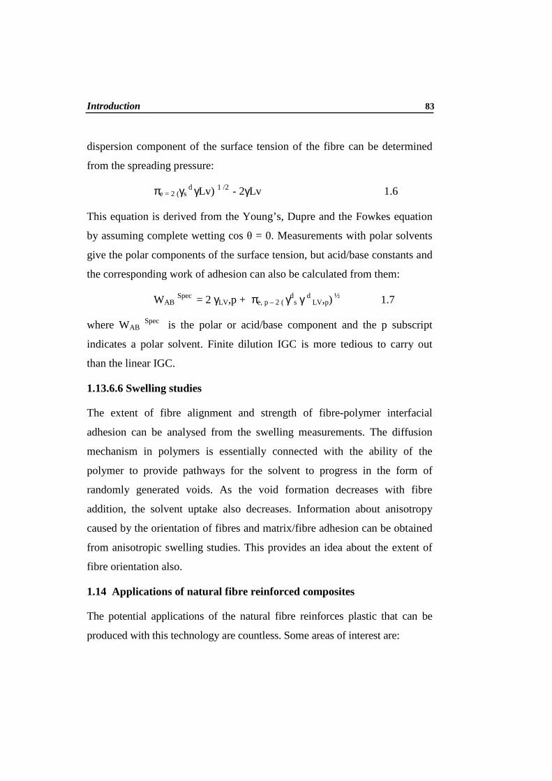
Introduction 83
dispersion component of the surface tension of the fibre can be determined
from the spreading pressure:
πe = 2 (γs d γLv) 1 /2 - 2γLv 1.6
This equation is derived from the Young’s, Dupre and the Fowkes equation
by assuming complete wetting cos θ = 0. Measurements with polar solvents
give the polar components of the surface tension, but acid/base constants and
the corresponding work of adhesion can also be calculated from them:
WAB Spec = 2 γLV,p + πe, p – 2 ( γds γ d
LV,p) ½ 1.7
where WAB Spec is the polar or acid/base component and the p subscript
indicates a polar solvent. Finite dilution IGC is more tedious to carry out
than the linear IGC.
1.13.6.6 Swelling studies
The extent of fibre alignment and strength of fibre-polymer interfacial
adhesion can be analysed from the swelling measurements. The diffusion
mechanism in polymers is essentially connected with the ability of the
polymer to provide pathways for the solvent to progress in the form of
randomly generated voids. As the void formation decreases with fibre
addition, the solvent uptake also decreases. Information about anisotropy
caused by the orientation of fibres and matrix/fibre adhesion can be obtained
from anisotropic swelling studies. This provides an idea about the extent of
fibre orientation also.
1.14 Applications of natural fibre reinforced composites
The potential applications of the natural fibre reinforces plastic that can be
produced with this technology are countless. Some areas of interest are:

84 Chapter 1
Automotive industry: fibre reinforced plastics can be used for inner and outer
parts. The advantages are that these composites are cheaper, more sustainable
and environmentally friendly than glass fibre reinforced composites. The
resulting products from those composites can be both re-used and incinerated
and do not have to be land filled as glass fibre compounds, which can help in
developing cars according to the EU End-of-Life directive. In interior
automotive applications they have the advantage of not injuring passengers
when an accident occurs because the fibres are soft and not harsh as glass
fibres.The total reported use of natural fibres has increased to more than 21
kiloton as stated by the suppliers to the European automotive industry (169).
In the past decade, natural-fibre composites with thermoplastic and thermoset
matrices have been embraced by European car manufacturers and suppliers for
door panels, seat backs, headliners, package trays, dashboards, and interior parts.
Natural fibres such as kenaf, hemp, flax, jute, and sisal offer such benefits as
reductions in weight, cost, and CO2, less reliance on foreign oil sources, and
recyclability. However, several major technical considerations must be
addressed before the engineering, scientific, and commercial communities gain
the confidence to enable wide-scale acceptance, particularly in exterior parts
where a Class A surface finish is required. Challenges include the
homogenization of the fibre's properties and a full understanding of the degree
of polymerization and crystallization, adhesion between the fibre and matrix,
moisture repellence, and flame-retardant properties, to name but a few. (170).
Packaging industry: for instance for light weight pallets. The advantages of
composite material compared to wood are weight reduction, which safes fuel
during transport, and re-use: chip-implementation makes it easy to trace them
and they can be remelted into new products at the end of their life-cycle.

Introduction 85
Consumer products: any injection moulded product. The advantages are
reduction of plastic's use, re-use and flame retandancy. Examples include
housing of household appliances like computers, refrigerators and cell phones.
The fibre structure of the composite makes these products become less
vulnerable for fire and they can be rejected to new products at the end of their
life-cycle. In addition, high fibre loads results in significant material cost
reduction.
Building and construction industry: for instance profiles and roofings. The
advantages are cost reduction, flame retardancy and re-use. The fibre
structure of the composite makes these products become less vulnerable for
fire and they can be remelted into new products at the end of their life-cycle.
In addition, high fibre loads results in significant material cost reduction.
In the last two decades, the developments in the field of natural fibre-
polymeric composites have grown from laboratory scale fundamental
research to industrial implementation. Nowadays, the use of natural fibres
especially in the automotive industry has become rather common practice.
Successfully implemented examples include both natural fibre-thermoset and
thermoplastic composites for interior applications like door panels, trim
parts, seatings and parcel shelves. Driven by environmental and cost
considerations slowly the focus shifts from thermoset- to thermoplastic-
based natural fibre composites. Natural fibre-reinforced composites are also
used in bioengineering and environmental engineering applications (142,171,
172). When glass fibre composites are replaced by natural fibre
composites,there will be a reduction in the weight by 10-20Kg. This can
bring about a significant reduction in fuel consumption leading to a positive
effect on the environment (173). Cherian et al. isolated nano cellulose from

86 Chapter 1
pineapple leaf fibres by steam explosion and reported that they have wide
range of biomedical and biotechnological applications (174).
1.15 Major challenges/gap
Utilization of lightweight natural fibres offers the potential to replace a large
segment of the glass and mineral fillers in numerous transportation
structures, both internal and external. In the past decade, natural-fibre
composites with thermoplastic and thermoset matrices have been embraced
by auto manufacturers and suppliers for interior door panels, seat backs,
headliners, package trays, dashboards, etc. Natural fibres such as kenaf,
hemp, flax, jute, and sisal are providing automobile reinforcement due to
such drivers as weight reduction, cost, CO2 reduction, less reliance on
foreign oil sources, recyclability, with the added benefit that these fibre
sources are “green” or eco-friendly. In the present work banana fibre has
been used as reinforcement in phenol formaldehyde resin matrix. Generally
the interaction of cellulose fibre with PF resin is splendid due to the
hydrophilic nature of cellulose and PF resin.
For the successful design of a composite material from banana fibre several
parameters such as fibre length, fibre loading, fibre surface modifications,
and fibre/matrix adhesion have to be optimized. To our knowledge no
serious attempt has been made so far to compare the efficiency of the CM
and RTM techniques for the production of banana fibre/ phenol
formaldehyde resin composite systems. Previous reports have shown that the
natural fibres are susceptible to moisture absorption, thermal degradation,
and biodegradation (175-179).

Introduction 87
Therefore, strategies need to be worked out to reduce these limitations. The
major aim of the present research work is to conduct a detailed investigation on
the development and characterisation of banana fibre/ phenol formaldehyde
resin composite systems fabricated by CM and RTM techniques. This includes
analysis of different processes such as surface modification of fibres with
different chemicals and characterisation using cellulose microfibrils and
nanofibrils separated from banana fibre as reinforcement in the resin. The
present study focuses on the following aspects.
1. A comparison on the properties of banana raw fibre, microfibril and
nanofibril.
2. Surface modifications of fibre and the effect of these modifications on
the surface morphology has been analysed by Fourier Transform
Infrared spectroscopy, Contact angle measurements, Solvatochromism
and electrokinetic studies.
3. The mechanical properties and viscoelastic properties were investigated
in detail to evaluate the fibre/matrix interactions and nature of
interface.
4. Water absorption is an important characteristic of composites for
applications where contact with moisture becomes essential.
5. Thermal stability of the raw fibre and cellulose micro and nanofibrils
was determined from TG and DTG curves.
The use of cellulose microfibrils and nanofibrils as reinforcement in polymer
matrix is a new and emerging field. These fibrils can be used to process
microfibril and nanofibril composite materials using a polymer as the matrix.
These composites are a relatively new class of composites that exhibit some

88 Chapter 1
unique and outstanding properties with respect to their conventional
composite. The present study also deals with the development of banana
microfibrils and nanofibrils from raw banana fibre by steam explosion
process followed by acid hydrolysis and fabrication of composites with phenol
formaldehyde matrix. The experimental details, results, discussion and
conclusions are presented.
1.16 Scope and objectives of the work
Composites based on thermosetting resins are now becoming popular due to
their processing advantages. Phenol formaldehyde (PF) is a commodity
polymer that has properties which can be extended into the applications of
high performance polymers. PF has become a universal polymer and it is
applied in each of the areas where special properties are required. PF provides
most of the advantages with regard to economic (price), ecological (recycling
behavior) and higher thermal stability (technical requirements). PF has low
density, sterilizability, good surface hardness, good abrasion resistance,
excellent electrical insulation properties and is available in many grades
differing in molar mass.
In the present work, banana fibre has been used as reinforcement in PF matrix.
Banana fibre, a waste product of banana cultivation, is abundantly available in
the state of Kerala. In India about 1.5M acres of land is cutivated with banana
plantations which yield about 3 x 10⁵ tons of the fibre. A large quantity of this
renewable fibre resource is being underutilized. Banana fibre is obtained from
the sheath of banana plants. The cellulosic fibre obtained from the pseudo-
stem of banana plant (Musa sepientum) is a bast fibre with relatively good
mechanical properties. Table 2.1 lists the mechanical properties of banana
fibre. X-ray studies on the fibre has shown that the structure is that of cellulose
Introduction 89
I. The fibre has a high degree of crystallinity, with good alignment of
crystallites parallel to the fibre axis. The crystalline cellulose in banana fibre is
arranged in the form of a helix at an angle of fibre 11–12o. When compared to
other natural fibres, banana fibre has good mechanical properties. In general,
the strength of a fibre increases with increasing cellulose content and
decreasing spiral angle with respect to the fibre axis. The major chemical
constituents of the fibre are cellulose (63–64%), hemicellulose (19%), and
lignin (5%). These properties can be advantageously utilized in reinforcing PF
which can increase the stiffness of PF and can favour good mechanical
properties.
The major objectives take account of the following
1. Utilisation of banana fibres as a reinforcement potential in
phenolformaldehyde composites
2. Isolation of cellulose fibrils
3. Surface modification and characterisation by different techniques.
4. Fabrication of composites using surface modified banana fibres by
RTM and CM
5. Comparative study of RTM and CM fabricated composites.
6. Fabrication of micro and nano composites.
7. Characterisation of the fabricated composites by different techniques.

90 Chapter 1
References
1 M. Idicula, N. R. Neelakandan, Z. Oommen, K. Joseph, S. Thomas,
J.Appl. Polym.Sci, 96, 1699, (2005)
2 A. P. Mathew, W. Thielmans, A. Dufresne, J.Appl. Polym. Sci., 109,
4065-4074, (2008)
3 J. lu, T. Wang, T. Lawrense Drzal Composites: Part A, 39, 738-746,
(2008)
4 J. L. Thomason, Composites: Part A, 40, 114-124, (2009)
5 N. Reddy Y. Yang, Green Chemistry, 7, 4, 190, (2005)
6 X. Cao, Y. Chen, R. Peter Chang, M. Stumborg, A. M. Heuniult,
J.Appl. Polym. Sci., 109, 3804-3810, (2008)
7 M. Igor, D.Rosa, C. Santulli, F. Sarasini Composites Part A: 40, 9,
1456, (2009)
8 A. Athijayamani, M. Thiruchitrambalam, U. Natarajan, B. Pazhanivel
Materials Science and Engineering: A, 517, 20, 344 (2009)
9 T. Behzad, M.Sain., Composites Sci. and Technol., 67, 1666, (2007)
10 N. Sgriccia, M. C. Hawley, M. Misra., Composites Part A: 39, 1632,
(2008)
11 Y. Ruksakulpiwat, J. Sridee, N. Suppakarn, W. Sutapun Composites
Part B: 40, 619, (2009)
12 S. V. Joshy, L. T. Drzal, A. K. Mohanty, S. Arora, Comp. Part A,
Appl. Sci. Manufacturing, 35, 371-376, (2004)
Introduction 91
13 M. Abdelmouleh, S. Boufia, M. N. Belgacem, A. Dufresne, Compos.
Sci. Technol., 67, 1627-1639, (2007)
14 L. Averoues, N Boquillon, Carbohydrate Polymers, 56, 111-122, (2004)
15 N.S.M.E1-Tayeb, Materials & Design, 30, 1151-1160, (2009)
16 P. Wambua, J. Ivens, I. Verpoest, Comp. Sci. and Technol., 63, 1259-
1264, (2003)
17 N. Netravali, S. Chabba, Composites get greener, Materials Today,
April (2003)
18 G. Francucci, E. S. Rodríguez, A. Vázquez,. Composites Part A: Appl.
Sci. and Manufacturing, 41, 16-21, (2010)
19. F.Gastón, E. S. Rodríguez, A. Vázquez, Composites Part A: Applied
Science and Manufacturing, 41, 16-21, (2010)
20. K.Oksman. Proc. Woodfibre-Plastic Composites Conf, Forest Prod
Soc, Madison, Wis, 97, (1999)
21. A. Bismarck, S. Mishra, T. Lampke. Natural fibres, Biopolymers and
Biocomposites; Eds. A. K. Mohanty, M. Misra and L. T. Drzal CRC
Press; Boca Raton, London, 37, (2005)
22. C.Brett, B.C.Suddel, W.J.Evans.,Natural Fibres, Biopolymers and
Biocomposites; Eds. A. K Mohanty, M. Misra, and L.T. Drzal, CRC
Press, Boca Raton, London, 231, (2005)
23. G.T. Pott, Upgraded natural fibres for Polymer Compos., 97,107,
(1997)

92 Chapter 1
24. M. Hintermann. Application of Natural Fibre Reinforced Plastics for
Automotive Exterior Parts with a Focus on Underfloor Systems, Proc
Int. Conf AVK-T, B 10-1, (2005)
25. Z. Li, X. Wan, L. Wang, Compos. Part A, 37, 497, (2006)
26. H. Savastano Jr., P. G. Warden, R. S. P. Coutts. Cement and Concrete
Compos. 25, 311, (2003)
27. A. K. Mohanty, M. Misra, L. T. Drzal, CRC Press, Boca Raton,
London, 37, (2005)
28. K. Mohanty, W. Liu, P Tummala, L. T Drzal, M Misra, R Narayan.
Natural fibres, Biopolymers and Biocomposite, Eds. A. K. Mohanty,
M. Misra, L. T. Drzal, CRC Press, Boca Raton London, 37, (2005)
29. K.G. Satyanarayana, G.C.Gregorio. A.F. Wypych, Progress in
Polymer Science, 34, 982-1021, (2009)
30. K. Bledzki, S. Reihmane, J. Gassan, J. Appl. Polym. Sci., 29, 1329-
1336, (1996)
31. L. A. Pothan, S. Thomas, Compos. Sci. and Technol., 63, 1231-1240,
(2003)
32. L. Uma Devi, S.S. Bhagawan, S. Thomas, J. Appl. Polym. Sci., 64,
1739-1748, (1997)
33. G. T. Toumis. Science and Technology of Wood: Structure, properties
utilization, New York, Van Nostrand Reinfold, 494, (1999)
34. N. J. Parratt, K. D. Potter Advances in Composite Materials (Eds)
Bunsell A. R, Bathias C, Martrenchar A, Menkes D, Verchery G.
Pergamon Press, 313-26, (1980)

Introduction 93
35. G. E. Kritschewsky Chemische technology von textil materialien,
Moskau, Legprombitisdat (1985)
36. J. Gassan, A. K. Bledzki 7. Internationales Techtexil Symposium,
Frankfurt, 20 - 22 June (1995)
37. F. Sadov, M. Korchagin, A. Matetsky Chemical Technology of fibrous
Materials, Mir Publishers, Moscow, (1978)
38. K. G. Satyanarayana, K. K. Ravikumar, K. Sukumaran, P. S.
Mukherjee, S. G. K. Pillai, A. K. Kulkarni, J. Mater. Sci., 21, 57
(1986)
39. A.K. Bledski, M. Letman, A. Viksne, L. Rence, Comp.Part A, 36,6
789, (2005)
40. S. Ndazi, S. Karlsson, J. V. Tesha, C. W. Nyahumva, Compos Part A,
38, 925-935, (2007)
41. E. T. N. Bisanda, M. P. Ansell, J. Mater. Sci., 27, 1690-1700, (1992)
42. P. Schniewind, Wood and fire, in: M.B. Bever (Ed.), Encyclopedia of
Materials Science and Engineering, Vol.7, 1st edition, Pergamon Press,
Oxford (1986)
43. K. G. Satyanarayana, A. G. Kulkarni, Rohatgi P. K. J. Scient. lnd.
Res., 42, 425 (1983)
44. G. Williams, R. P. WoolAppl. Comp. Mater., 7, 421, (2000)
45. J. D. Megiatto Jr., E. C. Ramires, E. Frollini, Industrial Crops and
Products, 31, 178-184, (2010)
46. S. Panthapulakkal, M.Sain, Compos. Part A, 38, 1445, (2007)

94 Chapter 1
47. V. Tserki., P. Matzinos, C. Panayiotou, Composites Part A, Appl. Sci
and Manufacturing, 37, 1231-1238, (2006)
48. A.P. Mathew, K. Oaksman, M. Sain, J.Appl. Polym. Sci., 101, 300-
310, (2006)
49. P. A. Sreekumar, K. Joseph, G. Unnikrishnan, S. Thomas, Compos.
Sci. Tech., 67, 453, (2007)
50. M. J. John, S. Thomas, Carbohydrate Polymers, 71, 343-364, (2008)
51. M. N. Kalaprasad, M. A. Gadyal, R. K. Hiermath, M. Ikram, B. G.
Mulimani, I. M. Khazi, S. K. Anantha Krishnan, M. K. Rabinal,
Compose Sci. and Technol., 68, 1787-1793, (2008)
52. H. Ismail, F. S. Haw, J.Appl. Polym.Sci., 110, 2867-2876, (2008)
53. M. Jacob, S. Thomas, K. T. Varghese, J.Appl. Polym. Sci., 93, 5, 2305,
(2004)
54. D. Chattopadhay, M.K. Bain, J.Appl. Polym.Sci., 110, 2849-2853,
(2008)
55. L. A. Pothen, S Thomas, Compose. Sci. Tech.,63,1231-1240, (2003)
56. A. Pizzi, R. Kueny, F. Lecoanet, B. Massetau, D. Carpentier, A.
Krebs, F. Loiseau, S. Molina, M. Ragoubi, Industrial Crops and
Products, 30, 235-240, (2009)
57. M. Idicula, P. A. Sreekumar, K. Joseph, S. Thomas, Polym.Compose,
30, 1417-1425, (2009)
58. A. Baker, T. B. Keat, A. Hassan, J. Appl. Polym. Sci., 115, 91-98,
(2010)

Introduction 95
59. P. Alvarez de Arcaya, A. A. Retegi, A. Arbelaiz, J. M. Kenni, I.
Montragon, Polym. Compos., 30,257-264, (2009)
60. X. Fan, L. Zhong-Wen, Zhao-Tie L, Ind.Eng.Chem. Res., 48, 6212-
6215, (2009)
61. G. Mougin, M. Magnani, N. Eikelenberg, International Journal of
Materials and Product Technology, 36, 176, (2009)
62. N. Dash, A. K. Rana, H. K. Mishra, S. K. Nayak, S. C. Mishra, S. S.
Tripathy, Polym. Compos. 20, 62, (1999)
63. N. E. Marcivich, M. M. Reboredo M. I. Aranguren. Compos.
Interfaces12, 3, (2005)
64. Q. T. Endo, T. Takahir. J. Appl. Polym. Sci. 94, 1326, (2004)
65. L. Medina, R. Schledjewski, A. K. Schlarb, Compos. Sci. and
Technol, 69, 1404-1411, (2009)
66. T. Zheng, D. R. Cao, D. S. Wang J. J. Chen. Compos. Part A 38, 20,
(2007)
67. H. Demir, U. Atikler, D. Balkose, F. Tihmihoglu. Compos. Part A 37,
447, (2006)
68. S. Karmarkar, S. Chauhan, J. M. Modak, M. Chandra, Compos. Part
A: Appl. Sci. and Manuf. 38, 227, (2007)
69. A.Arbelaiz, B. Fernandez, A. Valea, I. Mondragon. Carbohydate
Polym. 64, 224, (2006)
70. S. Mohanty, S. K. Verma S. K. Nayak. Compos. Sci. Technol. 66,
538, (2006)

96 Chapter 1
71. B. K. Ray, S. Das, A. K. Rana. Compos. Sci. Technol. 62, 911, (2002)
72. S. Mishra, M. Misra, S.S. Tripathy, S.K. Nayak, A.K. Mohanty, J.
Reinf. Plast. Compos. 20, 321, (2001)
73. S. H. Aziz, M. P. Ansell.,Compos. Sci. Technol. 64, 1219, (2004)
74. A. K. Dash, H. K. Rana, S. K. Nayak, S.C. Mishra, S.S. Tripathy.
Polym. Compos. 20, 62, (1999)
75. M. E. Marcovich, M. M. Reboredo, M. I. Aranguren. Compos.
Interfaces 12, 3, (2005)
76. M. Idicula, A. Boudenne, L. Umadevi, L. Ibos, Y. Candau and S.
Thomas. Compos. Sci. Technol. 66, 2719, (2006)
77. D. Ray, S. Gupta. Ind. Eng. Chem. Res. 45, 2722, (2006)
78. L. A. Pothen, S. Thomas, G. Groeninckx. Compos. Part A 37, 1260,
(2006)
79. Kaddami, A. Dufresne, B. Khelifi, A. Bendahou, M. Taourirte and M.
Raihane Compos. Part A 37, 1413, (2006)
80. S. Varghese, S.Thomas, B.Kuriakose, Rubber Chem. Tech.,68,37,(1995)
81. A.Byars, L.Jong, J.Appl.Polym.Sci.,111, 2049-2055, (2009)
82. V. G. Geethamma, R. Joseph, S. Thomas. J. Appl.Polym. Sci. 55, 583,
(1995)
83. L. Mathew, K. U. Joseph, R. Joseph., Bull. Mat. Sci. 29, 91, (2006)
84. P. Hasena, G.Unnikrishnan. Proceedings from International
Conference on Advances in Polymer Blends and Composites (ICBC
2005), March 21-23, (2005)

Introduction 97
85. S. Miryeong, H. S. David, M. W. Herbert, A. E. Danny, B. E. Franklin.
Appl. Spectr. 60, 437, (2006)
86. K. R. Lekha, V. Kavitha, J. Geotext, Geomembr. 24, 38, (2006)
87. P. S. Mukherjee, K. G. Satyanarayanan. J. Mater. Sci. 19, 3925,
(1984)
88. Z. Scida, M. L. Aboura, E. Bocherens, Compos. Sci. Technol. 59, 505,
(1999)
89. F. Gao, L. Boniface, S. L. Ogin, P.A. Smith, R. P. Greaves. Compos.
Sci. Technol. 59, 123, (1999).
90. A. Foulk, W.Y. Chao, D. E. Akin, R. B. Dodd, P. A Layton. J.
Polym. Environ. 14, 1007, (2006)
91. A. Wazzan, Inter. J. Polym. Mater. 54, 213, (2005)
92. Y.Lee,. Y.W.Mai, L. Ye., Comp. Interfaces 12, 141, (2005)
93. M. Jacob, K. T. Varghese, S. Thomas. J. Compos. Mater. 40, 1471,
(2006)
94. M. Jacob, K. T. Varghese, S. Thomas. J. Appl. Polym. Sci. 102, 1, 416,
(2006)
95. T. D. Downing., R. Kumar W. M .Cross, L. Kjerengtroen, J. J. Kellar
J. Adhesion. Sci. Tech., 14, 14, 1801 (2000)
96. B. S. Westerlind, J. C. Berge, J. Appl. Polym. Sci., 36, 523-534, (1988)
97. D. Maldas, B.V. Kokta, C. Danuelf, J. Appl. Polym. Sci., 37, 751-775,
(1989)

98 Chapter 1
98. V. M. Fonseca, V. J. Fernandez, L.H. de Carvalho, J.R.M. d’ Almeida,
J.Appl. Polym. Sci., 94,120-127, (2004)
99. S. K. Pal, D Mukhopadhyay, S. K. Sanyal, R. N. Mukherjee, J. Appl.
Polym. Sci., 35,973-985, (1988)
100. A. Pizzi, R. Kueny, F.Lecoanet, B. Massetau, D. Carpentier, A. Krebs,
F. Loiseau, S. Molina, M. Ragoubi, Industrial Crops and Products, 30,
235-240, (2009)
101. E. C. Ramires, D Jackson. Megiatto Jr., C. Gardrat, A. Castellan, E.
Frollini, Bioresource Technology In Press, Corrected Proof, Available
online 31October, (2009)
102. G. K. Satyanarayana, G. C. Gregorio Arizaga, F. Wypych, Progress in
Polymer Science, 34, 982-1021, (2009)
103. J.L.Thomason,Compos.Part A,40,114, (2009)
104. M. J. John, S. Thomas, Carbohydrate Polymers, 71, 343-364, (2008)
105. M. Zampaloni, F. Pourghrat, S. A. Yankovich, B. N. Rodgers, J.
Moore, L. T. Drzal, A. K. Mohanty, M. Misra, Composites Part A,
Appl.Sci. Manufacturing, 38, 1569-1580, (2007)
106. H. J. Kim, D. W. Seo, Inter.J. Fatigue, 28, 1307-1314, (2006)
107. S. H. Lee, S. Wang, Composites Part A, Appl.Sci.Manufacturing 37,
80-81, (2006)
108. N. S. M. El-Tayeb, Materials & Design, 30, 4023-4034 (2009)
109. N.S.M. El-Tayeb, Wear, 265, 223-235, (2008)

Introduction 99
110. J.D. Megiatto Jr., E.C. Ramires, E. Frollini, Industrial Crops and
Products, 31, 178-184, (2010)
111. M. Khalid, C.T. Ratnam, T.G. Chuah, Salmiaton Ali, Thomas S.Y.
Choong Materials & Design, 29, 173-178, (2008)
112. J. Gou, Y. Tang, F. Liang, Z. Zhao, D. Firsich J. Fielding, Composites
Part B, 40, 591, (2009)
113. E. Rodríguez, R. Petrucci, D. Puglia, J. M. Kenny, A. Vázquez, J.
Composite Materials, 39, 265, (2005)
114. Y. Yan, X. Shi, J. Liu, T. Zhao, Y. Yu, J. Appl. Polym. Sci., 83, 1651,
(2002)
115. D. Rouison, M. Sain, M. Couturier, Compos. Sci. Technol, 64, 629,
(2004)
116. K. Potter, Resin Transfer Moulding. Chapman and Hall (1997)
117. D. Neilson, R. Pitchumani, Compos. Sci. Technol., 62, 283-298, (2002)
118. D. Neilson, R. Pitchumani Composites Part A, Appl.Sci. and
Manufacturing, 32, 1625-1637, (2001)
119. H. P. Darcy, H. P. G.: Les fontaines publiques de la Ville de Dijon,
Paris, France, Dalmont, (1856)
120. H. Shin, L. J. Lee, Polymer Composites, 19, p 626-639, (1998)
121. C. Visconti, A. Langella, M. Durante, The influence of injection
pressure on the permeability of unidirectional fibre preforms in RTM,
In 8th European Conference on Composite Materials, ECCM-8, 3-6
June, Naples, Italy, p737, (1998)

100 Chapter 1
122. S. Amico, C. Lekakou, Compos. Sci. Technol., 61, 1945-1949, (2001)
123. C. J. Kiuna, Q. P. V. Lawrence, P. D. Fontana, T. Lee, P. D. Selerland,
Composite Part A, Applied Science and Manufacturing, 33, 1497-
1503, (2002)
124. C. W. Judd,; W. W. Wright, SAMPE Journal, 14, 10-14, (1978)
125. J. T. Paul, J. B. Thomson, The importance of voids in the filament
wound structure, In: Proceedings of SPI Composite Institutes 20th
Annual Conference, IL, SPI, New York, (1965)
126. K. J. Bowles; S. Frimpong, J. Composite Materials, 26, 1487-1509,
(1992)
127. G. S. Springer, A model of the curing process of epoxy matrix
composites, Proceedings of ICCM 4, Tokyo, October, North Holland
Publishing Co., Amsterdam, 23, (1983)
128. C. Loos, G. S. Springer, J. Compos. Materials, 17,135-169, (1983)
129. J. L. Kardos, R. Dave, M. P. Dudukovic, Advanced Polymer Science,
80, 101-123, (1986)
130. M. K. Kang, W. I. Lee, H. T. Hahn, Compos. Sci. Technology, 60,
2427-2434, (2000)
131. D. Rouison, M.Sain, M.Couturier, Compos. Sci. Technol, 64, 629-624,
(2004)
132. N. Dansiri, N. Yanumet, J. W. Ellis, Polymer Composites, 23, 352-
360, (2002)

Introduction 101
133. M. O. W. Richardson, Z. Y. Zhang, Composite Part A, Appl. Sci.
Manufacturing, 31,1303-1310, (2000)
134. R. Rowell, J. L. O'Dell, R. K. Basak, M. Sarkar, International seminar
on jute and allied fibres, Changing global scenario held at Calcutta
(1998)
135. J. L. O'Dell, Natural fibres in resin transfer moulded composites, In:
Proceedings Wood Fibre Plastics Composites Symposium, Forest
Prod. Soc. Madisson, WI, 280, (1997)
136. G. Sebes, N. S. Cetin, C. A. S. Hill, M. Hugues, Appl. Composite
Material, 7, 341-349, (2000)
137. K. Oksman, J. Reinforced Plastics and Composites, 20, 621-627,
(2001)
138. N. T. Boi, A. Maazouz, Polymer International, 53, 591-602, (2004)
139. A. Warrior, T. A. Turner, F. Robitaille, C. D. Rudd, Composite Part A:
Applied Science and Manufacturing, 34, 543-550, (2003)
140. M. J. Jacob, R. D. Anandjiwala, L. A. Pothan, S. Thomas. Compos.
Interfaces, 14,733, (2007)
141. C. Baillie. Green Composites: Polymer Composites and the
Environment. CRC Press, (2005)
142. Z. Wang, Q. Hu, X. Dai, H. Wu, Y. Wang, J. Shen, Polym. Compos.,
30, 1517-1522, (2009)
143. X. Huang, A.Netravali, Compos. Sci. Technol., 69, 1009-1015, (2009)

102 Chapter 1
144. N. Graupner, A. S. Hermann, J. Mussig, Compos. Part A, 40, 810-821,
(2009)
145. S. H. Imam, P. Cinelli, S. H. Gordon E.Chiellini. J. Polym. Environ.
13, 1, (2005)
146. S. Singh, A. K. Mohanty, M. Misra, Compos. Part A, 41, 304, (2010)
147. N. Netravali, S. Chabba, Composites get greener, Composites,
people.cornell.edu (2003)
148. X. Huang and A. N. Netravali. Biomacromolecules 7, 2783, (2006)
149. S. Singh, A. K. Mohanty, Compos. Sci. Technol., 67, 1753-1763,
(2007)
150. I. Kvien, S. Bjørn Tanem, K. Oksman, Biomacromole. 6, 3160, (2005)
151. T.Zimmermann, N.Bordeanu, E.Strub, Carbohydrate Polymers, 79,
1086-1093, (2010)
152. N. L. G. de Rodriguez, W. Thielemans, A. Dufresne. Cellulose 13,
261, (2006)
153. D. Bondeson, A. Mathew, K. Oksman., Cellulose 13,171, (2006)
154. A. Bhatnagar, M. Sain. J. Reinf. Plasti. and Compos.24, 1259, (2005)
155. G.Cao, X.Chen, Z.H.Xu, X.Li, Composites Part B: Engineering 41,
33-41,(2010)
156. O.K.Park, N.H.Kim, G.H.Yoo, K.Y.Rhee, J.H.Lee, Composites Part B:
Engineering, 41, 2-7, (2010)
157. S.H.Lim, A.Dasari, G.T.Wang, Z.Z.Yu, Y.W.Mai, Q. Yuan, S.Liu,
M.S.Yong, Composites Part B: Engineering, 41, 67-75, (2010)

Introduction 103
158. J.L.Tsai, .S.H.Tzeng, Y.T.Chiu, Composites Part B: Engineering, 41,
106-115, (2010)
159. G. Siqueira, J. Bras, A. Dufresne, Biomacromolecules, 10, 425–432
425, (2009)
160. P. K. Maji, Prasanta K. Guchhait, A. K. Bhowmick, Appl. Materials &
Interfaces, Downloaded from http://pubs.acs.org on January 8, (2009)
161. T. G. Rials, M. P. Wolcott, J. M, Nassar, J. Appl. Polym. Sci., 80, 546-
555, (2001)
162. J. K. Kim, A.Hodzic, J.Adhesion, 79, 383-414, (2003)
163. L. A. Pothan, F. Simon, S. Spange, S. Thomas, Biomacromolecules, 7,
892-898, (2006)
164. J.George, S. S. Bhagawan, S. Thomas, Composite Interfaces, 5, 201-
223, (1998)
165. X. Colom, F. Carrasco, P. Pages, J. Canavatc, J. Compos. Sci. Technol,
63, 161-169, (2003)
166. S. J.Eichorn, R. J. Young, J. Compos. Sci. Technol, 63, 1225-30, (2003)
167. K. Mai, E. Mader, M. Muhle, Composites Part A: Appl. Sci.
Manufacturing, 29, 1111 -1119, (1998)
168. V. Dupres, T. Camesano, D. Langevin, A. Checco, P. Guenoun, J.
Colloid and Interface Science, 269, 329-355, (2004)
169. B.C. Suddel, W.J. Evans, “Natural fibre composites in automotive
Applications”, in: Natural fibres, Biopolymers and biocomposites, A.K
Mohanty, M. Misra, L.T.Drzal, Eds., CRC Press USA, (2005)

104 Chapter 1
170. James Holbery, Dan Houston, J.Minerals, metals and materials
Society, 58, 80-86, (2006)
171. X. Huang, A. Netravali, Compos. Sci. Technol., 69, 1009-1015, (2009)
172. N. Graupner, A.S.Hermann, J.Mussig, Compos. Part A, 40, 810-821,
(2009)
173. L.A.Pothan, A.S.Luyt, S.Thomas, Polyolefin composites, Eds.
D.Nwabunma and T.Kyu, John Wiley and sons, (2007)
174. B.M.Cherian, A.L.Leao, S.F.de Sousa, S.Thomas, L.A.Pothan,
M.Kottaisamy, Carbohydrate Polymers, Article in press (2010)
175. M. S. Sreekala, S. Thomas., Comp Sci Technol, 63, 861, (2003)
176. V. Joseph, M. S. Rabello, LHC Mattoso , K. Joseph, S. Thomas,
Comp. Sci. Technol., 62, 1357, (2002)
177. M. S. Sreekala, M. G. Kumaran, S. Thomas, Comp Part A, 33, 763,
(2002)
178. J. George, S. S. Bhagawan, S. Thomas, Comp Sci Technol, 58, 1471,
1998
179. L. A. Pothen, N.R. Neelakantan, S. Thomas, J. Reinf. Plast. Comp., 16,
8, (1997)