1 g-2 phase study from geant simulation qinzeng peng advisor: james miller boston university sep 28,...
Post on 21-Dec-2015
214 views
TRANSCRIPT

11
g-2 g-2 phasephase study study from from GEANTGEANT simulation simulation
Qinzeng PengQinzeng Peng
Advisor:Advisor: James Miller James Miller
Boston UniversityBoston University
Sep 28, 2004Sep 28, 2004
Muon g-2 collaboration at BU: Muon g-2 collaboration at BU:
Lee Roberts, Rober Carey, Jon Paley, Xiaobo HuangLee Roberts, Rober Carey, Jon Paley, Xiaobo Huang
Institutes:Institutes:
BU, BNL, UIUC, Univ. of Minnesota, Yale Univ.BU, BNL, UIUC, Univ. of Minnesota, Yale Univ.

22
Outline Outline
I.I. Brief introduction to g-2Brief introduction to g-2
II.II. Experimental set up and simulationExperimental set up and simulation
III.III. Simulation results and analysisSimulation results and analysis
33
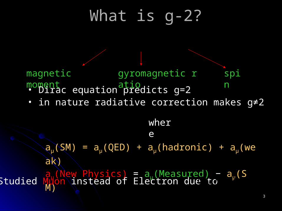
What is g-2?What is g-2?
sm
egSS
)
2(
)2
)(1(m
eα
magnetic moment gyromagnetic ratio spin
• Dirac equation predicts g=2• in nature radiative correction makes g≠2
2
2
ga
aμ(SM) = aμ(QED) + aμ(hadronic) + aμ(weak)
aμ(New Physics) = aμ(Measured) − aμ(SM)
where
Studied Muon instead of Electron due to 40000)( 2 em
m

44
Inflector
Kicker Modules
Storagering
Ideal orbitInjection orbit
Pions
Target
Protonsπ
(from AGS) p=3.1GeV/c
Experimental Setup – Muon storage
π μν
S
Polarization
Momentum
B
• Muon polarization• Muon storage ring• injection & kicking• focus by Quadrupoles R=711.2cm
d=9cm
(1.45T)
Electric Quadrupoles
E

55
spin precession and muon decayspin precession and muon decay)()(1()(),( /
0 twCosEAeENEtN t )()(1()(),( /0 twCosEAeENEtN t )()(1()(),( /0 twCosEAeENEtN t
• muons move in circle with constant speed• spin precession (Thomas + Larmor)• electrons decay mostly along the spindirection and boosted by Pmuon
• fitting by 5-parameter function to get
mceB
cs a )1()1(
N(t,E) = N0(E)e-t/τ(1+A(E)Cos(ωat+Φ(E))
mceB
csa a
B
P
S
nscmceB
c 2.149;1
DET
eve
])([1
12 EaBaw mc
ea
magic γ= 29.3
a

66
Phase shift on Phase shift on ωωa a uncertaintyuncertainty
))cos(1()( /0 tAeNtN t
tt 00)(
What if φ is not a constant?
Take an example: if mrad1
And measuring time is about 600 μs, then
00 )()()( tttt t
t/
ppmsrad
smrad
w16.1
/44.1
600/1

77
g2Geant simulationg2Geant simulation
Inflector
Ideal orbit
π
p≈3.1GeV/c B
DET
Beam-line simulation
g2Track
g2GEANT
Simulates nearly all geometric set up in the storage ring
• Inflection• Kicking• scraping
Jon Paley
Hugh Brown
Robert Carey
• Muons generation• Spin polarization

88
Beam-line / Calorimeter alignmentBeam-line / Calorimeter alignment
vertical
horizontal
Radial in Beam
Radial on DET
Vert. in Beam Vert. on DET
Beam in the ringCalorimeter
tdecay-tmeasure=drift time

99
Data selectionData selection
Energy cutEnergy cut : En >1.8GeV: En >1.8GeV Detector dependenceDetector dependence : average over 24 : average over 24
detectorsdetectors Drift timeDrift time : offset of g-2 phase: offset of g-2 phase
)))(cos()(1()(),( /
0 EtEAeENtEN t
dttt measuredecay
nsmraddtperiodgone
timedrift dtdt /44.12 2

1010
Beam
ФФ vs. detector vertical position vs. detector vertical position
• Symmetric about center• Energy dependent• ΔΦ big : -80 ~ +80 mrad• Φ(all) small : about 5 mrad • Φ change sign at 3cm
3cm
DET
ypc1

1111
outward and inward decayoutward and inward decay
outwardoutward Φ < 0< 0 dt longerdt longerinwardinward Φ > 0> 0 dt shorterdt shorter
3cm
outward
inward

1212
ФФ vs. detector radial position vs. detector radial position
• ΔΦ smaller, 30 mrad• Φ ≈0 on outside• Φ >0 on detector

1313
ФФ vs. beam vertical/radial position vs. beam vertical/radial position
• symmetric about center of beam•ΔΦ big• Φ ≈0 at center
• ΔΦ smaller• Φ ≈0 on inside• Φ >0

1414
Beam vertical shiftBeam vertical shift
• ΔΦ ≈0 • Φ is detector dependent, 4 groups --- 4 Quads

1515
Beam width changeBeam width change
idea: change beam vertical distribution by a weighting factor
Result : 1 percent width change / 0.1 mrad phase shift

1616
Beam upper cut – muon lossesBeam upper cut – muon losses
cut at 3cm
vert
ical
• Muon losses: 1.64%• ΔΦ = -0.323 mrad
9cm

1717
Detector gain shiftDetector gain shift
• very small effect
• 10% gain shift /
ΔΦ = 0.014 mrad
DET Vert.E
1.05 E
0.95 E

1818
Beam / detector vertical alignmentBeam / detector vertical alignment
• 0.9mm/1.0mm shift • 0.11%/1.0% width change

1919
CBO modulationCBO modulation
Betatron OscillationBetatron Oscillation
))cos(1()(
))cos(1()(
))cos(1()(
0
0
0
tAt
tAAtA
tANtN
CBO
ACBOA
NCBON
Combine 23 detectors in one CBO periodCombine 23 detectors in one CBO period
Time = MOD ( time - DET# /24*Tcbo, Tcbo)
Coherent Betatron OscillationCoherent Betatron OscillationBOCCBO
n
n
CYBO
CXBO
)1(

2020
Sampling Tcbo=2.4μs

2121
24
;24
1
DETTtt
orCID
Ttt
cbo
cbo
Combine 23 detectors CBO effect

2222
CBO modulation
Number modulation Asymetry modulation, 0.22%

2323
phase modulation, 0.358 mrad dt modulation, 0.175 mrad

2424
conclusionsconclusions
Simulation results consistent with Real datSimulation results consistent with Real data, like FSD studies.a, like FSD studies.
Phase shift due to the geometric set up is Phase shift due to the geometric set up is a small effect on a small effect on ωωa a ..
CBO effect is a small effect.CBO effect is a small effect.