1. general - aristotle university of thessaloniki means 3-phase short-circuit current. iscb means...
TRANSCRIPT

the protection of circuits - the switchgear - H1-1
H1
1. general
1.1 methodology and definitions
component parts of an electric circuitand its protection are determinedsuch, that all normal and abnormaloperating constraints are satisfied.
methodologyFollowing a preliminary analysis of the powerrequirements of the installation, as decribedin Chapter B Clause 4, a study of cabling*and its electrical protection is undertaken,starting at the origin of the installation,through the intermediate stages to the finalcircuits.The cabling and its protection at each levelmust satisfy several conditions at the sametime, in order to ensure a safe and reliableinstallation, e.g. it must:c carry the permanent full load current, andnormal short-time overcurrents,c not cause voltage drops likely to result in aninferior performance of certain loads, forexample: an excessively long accelerationperiod when starting a motor, etc.
Moreover, the protective devices (circuitbreakers or fuses) must:c protect the cabling and busbars for alllevels of overcurrent, up to and includingshort-circuit currents,
c ensure protection of persons againstindirect contact hazards, particularly inTN- and IT- earthed systems, where thelength of circuits may limit the magnitudeof short-circuit currents, thereby delayingautomatic disconnection (it may beremembered that TT- earthed installations areobligatorily protected at the origin by a RCD,generally rated at 500 mA).The cross-sectional areas of conductors aredetermined by the general method describedin Sub-clause 1.2 of this Chapter. Apart fromthis method some national standards mayprescribe a minimum cross-sectional area tobe observed for reasons of mechanicalendurance. Particular loads (as noted inChapter J) require that the cable supplyingthem be oversized, and that the protection ofthe circuit be likewise modified.
* the term "cabling" in this chapter, covers all insulatedconductors, including multi-core and single-core cables andinsulated wires drawn into conduits, etc.
kVA to be supplied short-circuit MVA at the origin of the circuit
rated current of protectivedevice (C.B. or fuses)
short-circuit current-breaking rating of C.B. or fuses
choice of C.B. or fuses
verification of thermal withstand requirements
verification of the maximum voltage drop
IT or TN scheme
TT scheme
verification of the maximum length of the circuit
confirmation of the cross-sectional area of the cabling, and the choice of its electrical protection
determination of the cross-sectional areaof the conductors
choice of protective device
upstream or downstream network
cross-sectional area of conductors of the circuit
maximum load current
short-circuitcurrent
conditions of installation
IB
In
Isc
Iscb
table H1-1: logigram for the selection of cable size and protective-device ratingfor a given circuit.
H1-2 - the protection of circuits - the switchgear
H1
1. general (continued)
1.1 methodology and definitions (continued)
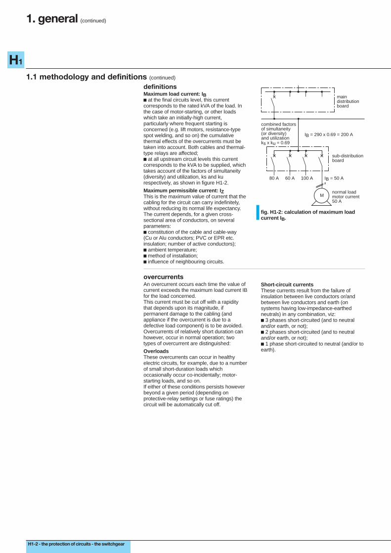
definitionsMaximum load current: I Bc at the final circuits level, this currentcorresponds to the rated kVA of the load. Inthe case of motor-starting, or other loadswhich take an initially-high current,particularly where frequent starting isconcerned (e.g. lift motors, resistance-typespot welding, and so on) the cumulativethermal effects of the overcurrents must betaken into account. Both cables and thermal-type relays are affected;c at all upstream circuit levels this currentcorresponds to the kVA to be supplied, whichtakes account of the factors of simultaneity(diversity) and utilization, ks and kurespectively, as shown in figure H1-2.
Maximum permissible current: I ZThis is the maximum value of current that thecabling for the circuit can carry indefinitely,without reducing its normal life expectancy.The current depends, for a given cross-sectional area of conductors, on severalparameters:c constitution of the cable and cable-way(Cu or Alu conductors; PVC or EPR etc.insulation; number of active conductors);c ambient temperature;c method of installation;c influence of neighbouring circuits.
maindistributionboard
sub-distributionboard
80 A 60 A 100 A IB = 50 A
Mnormal loadmotor current50 A
combined factorsof simultaneity(or diversity)and utilizationks x ku = 0.69
IB = 290 x 0.69 = 200 A
fig. H1-2: calculation of maximum loadcurrent I B.
overcurrentsAn overcurrent occurs each time the value ofcurrent exceeds the maximum load current IBfor the load concerned.This current must be cut off with a rapiditythat depends upon its magnitude, ifpermanent damage to the cabling (andappliance if the overcurrent is due to adefective load component) is to be avoided.Overcurrents of relatively short duration canhowever, occur in normal operation; twotypes of overcurrent are distinguished:
OverloadsThese overcurrents can occur in healthyelectric circuits, for example, due to a numberof small short-duration loads whichoccasionally occur co-incidentally; motor-starting loads, and so on.If either of these conditions persists howeverbeyond a given period (depending onprotective-relay settings or fuse ratings) thecircuit will be automatically cut off.
Short-circuit currentsThese currents result from the failure ofinsulation between live conductors or/andbetween live conductors and earth (onsystems having low-impedance-earthedneutrals) in any combination, viz:c 3 phases short-circuited (and to neutraland/or earth, or not);c 2 phases short-circuited (and to neutraland/or earth, or not);c 1 phase short-circuited to neutral (and/or toearth).
the protection of circuits - the switchgear - H1-3
H1
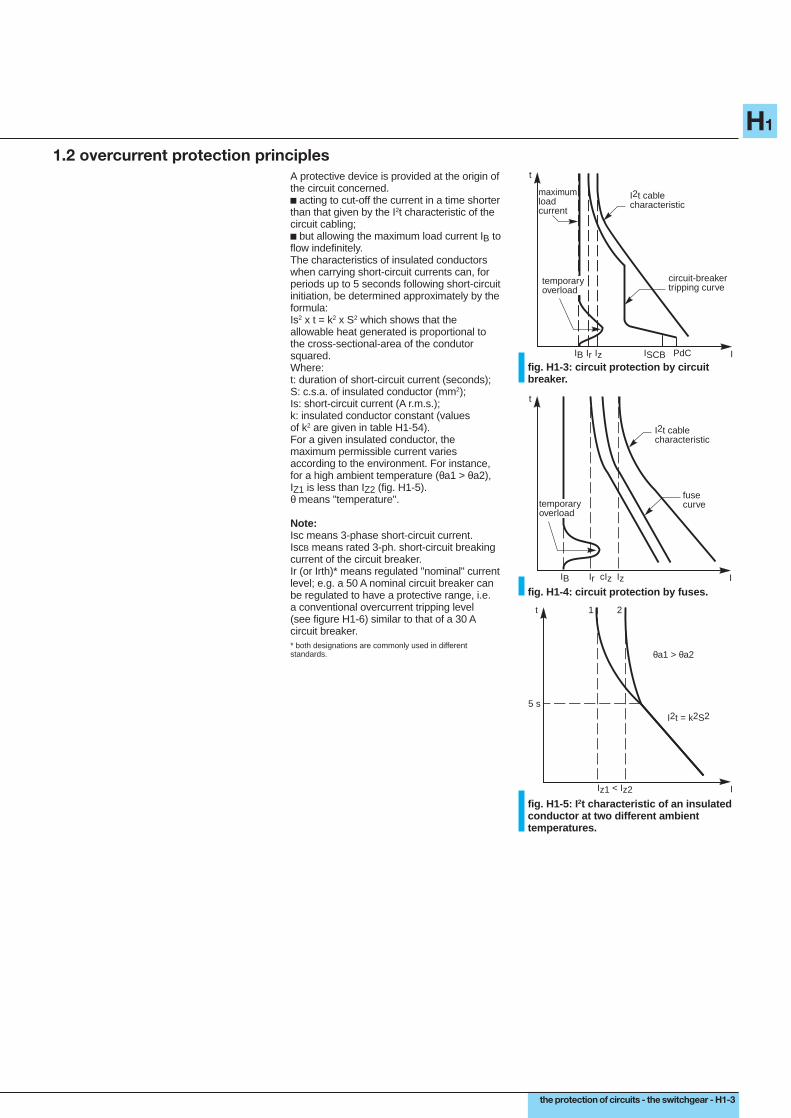
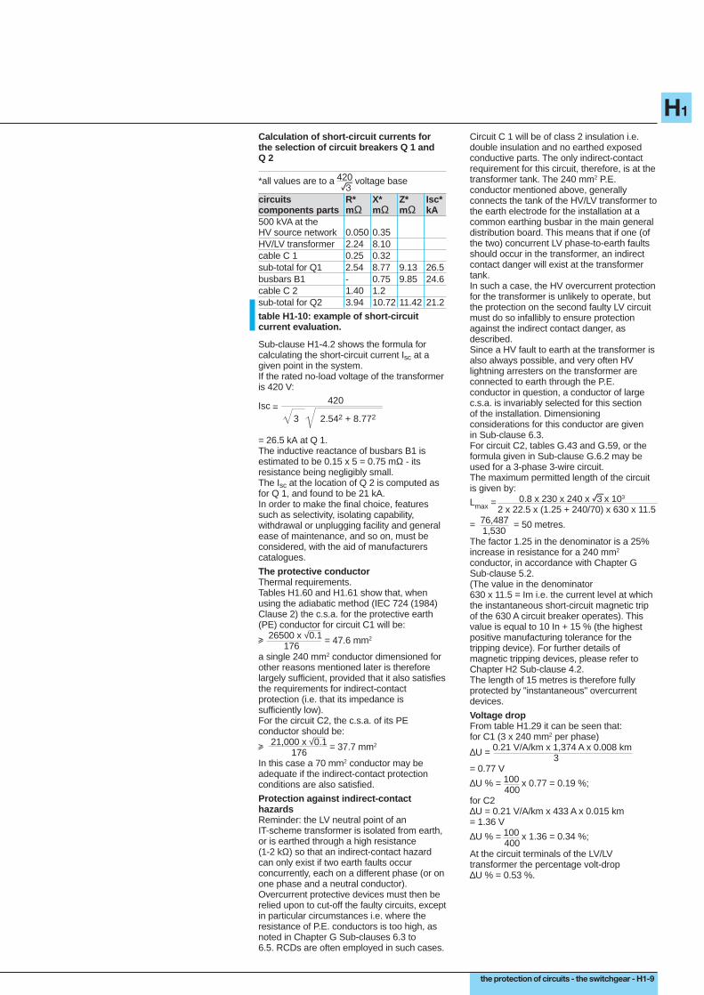
1.2 overcurrent protection principlesA protective device is provided at the origin ofthe circuit concerned.c acting to cut-off the current in a time shorterthan that given by the I2t characteristic of thecircuit cabling;c but allowing the maximum load current IB toflow indefinitely.The characteristics of insulated conductorswhen carrying short-circuit currents can, forperiods up to 5 seconds following short-circuitinitiation, be determined approximately by theformula:Is2 x t = k2 x S2 which shows that theallowable heat generated is proportional tothe cross-sectional-area of the condutorsquared.Where:t: duration of short-circuit current (seconds);S: c.s.a. of insulated conductor (mm2);Is: short-circuit current (A r.m.s.);k: insulated conductor constant (valuesof k2 are given in table H1-54).For a given insulated conductor, themaximum permissible current variesaccording to the environment. For instance,for a high ambient temperature (θa1 > θa2),IZ1 is less than IZ2 (fig. H1-5).θ means "temperature".
Note:Isc means 3-phase short-circuit current.IscB means rated 3-ph. short-circuit breakingcurrent of the circuit breaker.Ir (or Irth)* means regulated "nominal" currentlevel; e.g. a 50 A nominal circuit breaker canbe regulated to have a protective range, i.e.a conventional overcurrent tripping level(see figure H1-6) similar to that of a 30 Acircuit breaker.* both designations are commonly used in differentstandards.
t
IIB Ir Iz ISCB PdC
maximumloadcurrent
I2t cablecharacteristic
circuit-breakertripping curve
temporaryoverload
fig. H1-3: circuit protection by circuitbreaker.
t
I
I2t cablecharacteristic
fusecurve
IB Ir cIz Iz
temporaryoverload
fig. H1-4: circuit protection by fuses.
t
I
θa1 > θa2
Iz1 < Iz2
I2t = k2S25 s
1 2
fig. H1-5: I 2t characteristic of an insulatedconductor at two different ambienttemperatures.

H1-4 - the protection of circuits - the switchgear
H1
3-ph
shor
t-circ
uit
fault-c
urren
t brea
king r
ating
loads circuit cabling
max
imum
per
miss
ible
curre
nt I z
1.45
x I z
maxim
um load current IB
nom
inal c
urre
nt I n
or
its re
gulat
ed cu
rrent
I r
protective device
ISCBzone a
conv
entio
nal o
verc
urre
nt
trip
curre
nt I 2
zone b zone c
IB Iz
In I2
1.45 Iz ISC
1. general (continued)
1.3 practical values for a protection schemeThe following methods are based on ruleslaid down in the IEC standards, and are
representative of the practices in manycountries.
fig. H1-6: current levels for determining circuit breaker or fuse characteristics.
general rulesA protective device (circuit breaker or fuse)functions correctly if:c its nominal current or its setting current In isgreater than the maximum load current IB butless than the maximum permissible current IZfor the circuit, i.e. IB i In i IZ corresponding tozone "a" in figure H1-6;c its tripping current I2 "conventional" settingis less than 1.45 IZ which corresponds tozone "b" in figure H1-6.
IB i In i Iz zone aI2 i 1,45 Iz zone bISCB u ISC zone c
The "conventional" setting tripping time maybe 1 hour or 2 hours according to localstandards and the actual value selected forI2.For fuses, I2 is the current (denoted If) whichwill operate the fuse in the conventional time;c its 3-phase short-circuit fault-currentbreaking rating is greater than the 3-phaseshort-circuit current existing at its point ofinstallation.This corresponds to zone "c" in figure H1-6.
applicationsProtection by circuit breakerBy virtue of its high level of precision thecurrent I2 is always less than 1.45 In (or1.45 Ir) so that the condition, that I2 i 1.45 IZ(as noted in the "general rules" above) willalways be respected.
Particular case:if the circuit breaker itself does not protectagainst overloads, it is necessary to ensurethat, at a time of lowest value of short-circuitcurrent, the overcurrent device protecting thecircuit will operate correctly. This particularcase is examined in Sub-clause 5.1.
criteria for a circuit breaker:IB i In (or Ir) i Izand,rated short-circuit breaking currentISCB u ISC the 3-ph. short-circuitcurrent level at the point of CBinstallation.
Protection by fusesThe condition I2 i 1.45 IZ must also be takeninto account, where I2 is the fusing (melting-level) current, equal to k2 x In (k2 ranges from1.6 to 1.9) according to the particular fuseconcerned.A further factor k3 has been introduced (in thenational standards from which these noteshave been abstracted) such that I2 i 1.45 IZwill be valid if In i IZ/k3.
For fuses type gl:In i 10 A k3 = 1.3110 A < In i 25 A k3 = 1.21In > 25 A k3 = 1.10Moreover, the short-circuit current breakingcapacity of the fuse ISCF must exceed thelevel of 3-phase short-circuit current at thepoint of installation of the fuse(s).
criteria for fuses:
IB i In i IZ k3and,the rated short-circuit currentbreaking capacity of the fuseISCF u ISC the 3-ph. short-circuitcurrent level at the point of fuseinstallation.
Association of different protective devicesThe use of protective devices which havefault-current ratings lower than the fault levelexisting at their point of installation arepermitted by IEC and many nationalstandards in the following conditions:c there exists upstream, another protectivedevice which has the necessary short-circuitrating, andc the amount of energy allowed to passthrough the upstream device is less than thatwhich the downstream device and all
associated cabling and appliances canwithstand without damage.In pratice this arrangement is generallyexploited in:c the association of circuit breakers/fuses;c the technique known as "cascading" inwhich the strong current-limiting performanceof certain circuit breakers effectively reducesthe severity of downstream short-circuits.Possible combinations which have beentested in laboratories are indicated in certainmanufacturers catalogues.

the protection of circuits - the switchgear - H1-5
H1
1.4 location of protective devices
a protective device is, in general,required at the origin of each circuit.
general ruleA protective device is necessary at the originof each circuit where a reduction ofpermissible maximum current level occurs.
P
P2 P3 P4
50 mm2 10 mm2 25 mm2
P2
P3
(1) (2)
short-circuitprotectivedevice
P1
sc
sB
overloadprotectivedevice3
B
B
< 3 m
A
case (3)case case
possible alternative locations incertain circumstancesThe protective device may be placed partway along the circuit:c if AB is not in proximity to combustiblematerial, andc if no socket-outlets or branch connectionsare taken from AB.Three cases may be useful in practice.
Consider case (1) in the diagramc AB i 3 metres, andc AB has been installed to reduce to apractical minimum the risk of a short-circuit(wires in heavy steel conduit for example).
Consider case (2)c the upstream device P1 protects the lengthAB against short-circuits in accordance withSub-clause H1-5.1.
Consider case (3)c the overload device (S) is located adjacentto the load. This arrangement is convenientfor motor circuits. The device (S) constitutesthe control (start/stop) and overloadprotection of the motor while (SC) is: either acircuit breaker (designed for motor protection)or fuses type aM,c the short-circuit protection (SC) located atthe origin of the circuit conforms with theprinciples of Sub-clause H1-5.1.
P1: C60 calibre 15 A
S2:1,5 mm2
2,5 mm2
circuits with no protectionEitherc the protective device P1 is calibrated toprotect the cable S2 against overloads andshort-circuits;
Orc where the breaking of a circuit constitutes arisk, e.g.v excitation circuits of rotating machines,v circuits of large lifting electromagnets,v the secondary circuits of currenttransformers.No circuit interruption can be tolerated, andthe protection of the cabling is of secondaryimportance.
table H1-7: general rules and exceptions concerning the location of protective devices.
1.5 cables in parallelConductors of the same cross-sectional-area,the same length, and of the same material,can be connected in parallel.The maximum permissible current is the sumof the individual-core maximum currents,taking into account the mutual heatingeffects, method of installation, etc.Protection against overload and short-circuitsis identical to that for a single-cable circuit.
The following precautions should be taken toavoid the risk of short-circuits on theparalleled cables:c additional protection against mechanicaldamage and against humidity, by theintroduction of supplementary protection;c the cable route should be chosen so as toavoid close proximity to combustiblematerials.

H1-6 - the protection of circuits - the switchgear
H1
1. general (continued)
1.6 worked example of cable calculationsinstallation schemeThe installation is supplied through a1,000 kVA transformer. The process requiresa high degree of supply continuity and this isprovided by the installation of a 500 kVA400 V standby generator, and by the adoptionof a 3-phase 3-wire IT-system at the maingeneral distribution board from which theprocessing plant is supplied. The remainderof the installation is isolated by a 315 kVA400/400V transformer: the isolated network isa TT-earthed 3-phase 4-wire system.
Following the one-line diagram of the systemshown in figure H1-8 below, a reproduction ofthe results of a computer study for the circuitC1 and its circuit breaker Q1, and C2 withassociated circuit breaker Q2 are presented.These studies were carried out withECODIAL 2.2 software (a Merlin Gerinproduct).This is followed by the same calculationscarried out by the methods described in thisguide.
Q6Q5
Q8 Q9 Q10
Q4Q3
TR11000 kVA5%
400 V26. 44 kA
3x (3 x 240)
C18m.18%
Q1M16 N1STR 381600 A
B1
Q2C801NSTR35SE800 A
C215m.7%
3x (1 x 240)
C3
T1315 kVA
400 V
Q7NS630NSTR35SE630 A
B2
G1500 kVA721 A
C4
I1 I2
Q11NS250NTMD250 A
Q12NS160NTMD160 A
Q13NS100NTMD80 A
fig. H1-8: one-line diagram of the installation.

the protection of circuits - the switchgear - H1-7
H1
calculations using software Ecodial 2.2
General network characteristicsearthing system ITneutral distributed Nvoltage (V) 400frequency (Hz) 50
Transformer TR 1 input data outputnumber of transformers 1upstream fault level (MVA) 500rating (kVA) 1000short-circuit impedance voltage (%) 5remarksnominal current (A) 1374resistance of transformer (mΩ) 2.13reactance of transformer (mΩ) 8.55running total of impedance RT (mΩ) 2.18running total of impedance XT (mΩ) 8.93-phase short-circuit current (kA) 26.44short-circuit power factor .23
Cable C 1 input data outputmaximum load current (A) 1374type of insulation PRCconductor material Cuambient temperature (°C) 30single-core or multi-core cable UNIinstallation method 13number of circuits in close proximity(table H1-14) 1other coefficient 1number of phases 3selected cross-sectional area (mm2) 3 x 240protective conductor 1 x 240neutral conductorlength (m) 8voltage drop ∆U (%) .18running total of impedance RT (mΩ) 2.43running total of impedance XT (mΩ) 9.11voltage drop ∆U total (%) .183-phase short-circuit current (kA) 25.71-phase-to-earth fault current (A) 20334resistance of protective conductor RPE (mΩ) .75touch voltage (V) 15
Circuit breaker Q 1 input data outputvoltage (V) 4003-ph short-circuit current upstreamof the circuit breaker (kA) 25.7maximum load current (A) 1374ambient temperature (°C) 40number of poles 3circuit breaker M 16type N 1tripping unit type STR 38rated current (A) 1600
Busbars B 1maximum load current (A) 1374number of phases 3number of bars per phase 1width (mm) 125thickness (mm) 5length (m) 3remarksimpedance of busbars R (mΩ) .1impedance of busbars X (mΩ) .45voltage drop ∆U(%) .16running total of impedance RT (mΩ) 2.53running total of impedance XT (mΩ) 9.55voltage drop ∆U total (%) .343-ph short-circuit current (kA) 24.53

H1-8 - the protection of circuits - the switchgear
H1
1. general (continued)
1.6 worked example of cable calculations (continued)
Circuit breaker Q 2 input data outputvoltage (V) 4003-ph short-circuit current upstreamof the circuit breaker (kA) 24.53maximum load current (A) 433ambient temperature (°C) 40number of poles 3circuit breaker NS630type Ntripping unit type STR23SErated current (A) 6303-phase fault current (A) 13221protection against indirect contact assuredupstream circuit breaker M16 N1 STR38absolute discrimination
Cable C 2 input data outputmaximum load current (A) 433type of insulation PRCconductor material Cuambient temperature (°C) 30single-core or multi-core cable UNIinstallation method 13number of circuits in close proximity(table H1-14) 1other coefficient 1number of phases 3selected cross-sectional area (mm2) 1 x 240protective conductor 1 x 70neutral conductorlength (m) 15voltage drop ∆U (%) .33running total of impedance RT (mΩ) 3.93running total of impedance XT (mΩ) 10.75voltage drop ∆U total (%) .673-phase short-circuit current (kA) 21.181-phase-to-earth fault current (A) 13221resistance of protective conductor RPE (mΩ) 5.57touch voltage (V) 73
table H1-9: calculations carried out with ECODIAL software (M.G).
the same calculations usingthe methods recommended inthis guideDimensioning circuit C 1The HV/LV 1,000 kVA transformer has a ratedno-load voltage of 420 V. Circuit C 1 must besuitable for a current of 1,000In =
ex 0.42 = In = 1,374 A per phase
Three single-core XLPE-insulated coppercables in parallel will be used for each phase;these cables will be laid on cable trayscorresponding with reference F (see tables inClause H1 2.2). The "K" correction factors areas follows:K 1 = 1K 2 = 0.82 ( 3 three-phase groups in a singlelayer)K 3 = 1 (temperature 30 °C).If the circuit breaker is a withdrawable orunpluggable* type, which can be regulated,one might choose:Iz = 1,374 A applying H1.2.1
I’z = Iz = 1,676 A. K 1 x K 2 x K 3Each conductor will therefore carry 558 A.Table H1-17 indicates that the c.s.a. is240 mm2.* Withdrawable, CBs are generally mounted in drawers formaintenance purposes. Plug-in type CBs are generallymoulded-case units, which may be completely removedfrom the fixed-base sockets.
The resistances and the inductive reactancesfor the three conductors in parallel are, for alength of 8 metres (see H1-4.2):
R = 22.5 x 8 = 0.25 mΩ per phase 240 x 3
X = 0.12 x 8 = 0.32 mΩ per phase 3(0.12 mΩ/metre was advised by the cablemaker).
Dimensioning circuit C 2Circuit C 2 supplies a 315 kVA 3-phase400/400 V isolating transformer
Ib = 315 0.42 x e
= 433 A.
A multi-core XLPE cable laid on a cable tray(together with two other cables) in an ambientair temperature of 30 °C is proposed.The circuit breaker is regulated to 433 A.Iz = 433 AThe method of installation is characterized bythe reference letter E, and the "K" correctingfactors are:K 1 = 1K 2 = 0.82K 3 = 1.
I’z = 433 = 528 A so that 1 x 0.82 x 1a c.s.a. of 240 mm2 is appropriate.The resistance and inductive reactance arerespectively:
R = 22.5 x 15 = 1.4 mΩ per phase 240X = 0.08 x 15 = 1.2 mΩ per phase.
the protection of circuits - the switchgear - H1-9
H1
Sub-clause H1-4.2 shows the formula forcalculating the short-circuit current Isc at agiven point in the system.If the rated no-load voltage of the transformeris 420 V:
= 26.5 kA at Q 1.The inductive reactance of busbars B1 isestimated to be 0.15 x 5 = 0.75 mΩ - itsresistance being negligibly small.The Isc at the location of Q 2 is computed asfor Q 1, and found to be 21 kA.In order to make the final choice, featuressuch as selectivity, isolating capability,withdrawal or unplugging facility and generalease of maintenance, and so on, must beconsidered, with the aid of manufacturerscatalogues.
The protective conductorThermal requirements.Tables H1.60 and H1.61 show that, whenusing the adiabatic method (IEC 724 (1984)Clause 2) the c.s.a. for the protective earth(PE) conductor for circuit C1 will be:
u 26500 x √0.1 = 47.6 mm2
176a single 240 mm2 conductor dimensioned forother reasons mentioned later is thereforelargely sufficient, provided that it also satisfiesthe requirements for indirect-contactprotection (i.e. that its impedance issufficiently low).For the circuit C2, the c.s.a. of its PEconductor should be:
u 21,000 x √0.1 = 37.7 mm2
176In this case a 70 mm2 conductor may beadequate if the indirect-contact protectionconditions are also satisfied.
Protection against indirect-contacthazardsReminder: the LV neutral point of anIT-scheme transformer is isolated from earth,or is earthed through a high resistance(1-2 kΩ) so that an indirect-contact hazardcan only exist if two earth faults occurconcurrently, each on a different phase (or onone phase and a neutral conductor).Overcurrent protective devices must then berelied upon to cut-off the faulty circuits, exceptin particular circumstances i.e. where theresistance of P.E. conductors is too high, asnoted in Chapter G Sub-clauses 6.3 to6.5. RCDs are often employed in such cases.
=Isc 420
2.542 + 8.7723
Calculation of short-circuit currents forthe selection of circuit breakers Q 1 andQ 2
*all values are to a 420 voltage base ecircuits R* X* Z* Isc*components parts m Ω mΩ mΩ kA500 kVA at theHV source network 0.050 0.35HV/LV transformer 2.24 8.10cable C 1 0.25 0.32sub-total for Q1 2.54 8.77 9.13 26.5busbars B1 - 0.75 9.85 24.6cable C 2 1.40 1.2sub-total for Q2 3.94 10.72 11.42 21.2
table H1-10: example of short-circuitcurrent evaluation.
Circuit C 1 will be of class 2 insulation i.e.double insulation and no earthed exposedconductive parts. The only indirect-contactrequirement for this circuit, therefore, is at thetransformer tank. The 240 mm2 P.E.conductor mentioned above, generallyconnects the tank of the HV/LV transformer tothe earth electrode for the installation at acommon earthing busbar in the main generaldistribution board. This means that if one (ofthe two) concurrent LV phase-to-earth faultsshould occur in the transformer, an indirectcontact danger will exist at the transformertank.In such a case, the HV overcurrent protectionfor the transformer is unlikely to operate, butthe protection on the second faulty LV circuitmust do so infallibly to ensure protectionagainst the indirect contact danger, asdescribed.Since a HV fault to earth at the transformer isalso always possible, and very often HVlightning arresters on the transformer areconnected to earth through the P.E.conductor in question, a conductor of largec.s.a. is invariably selected for this sectionof the installation. Dimensioningconsiderations for this conductor are givenin Sub-clause 6.3.For circuit C2, tables G.43 and G.59, or theformula given in Sub-clause G.6.2 may beused for a 3-phase 3-wire circuit.The maximum permitted length of the circuitis given by:
Lmax = 0.8 x 230 x 240 x ex 103
2 x 22.5 x (1.25 + 240/70) x 630 x 11.5
= 76,487 = 50 metres. 1,530The factor 1.25 in the denominator is a 25%increase in resistance for a 240 mm2
conductor, in accordance with Chapter GSub-clause 5.2.(The value in the denominator630 x 11.5 = Im i.e. the current level at whichthe instantaneous short-circuit magnetic tripof the 630 A circuit breaker operates). Thisvalue is equal to 10 In + 15 % (the highestpositive manufacturing tolerance for thetripping device). For further details ofmagnetic tripping devices, please refer toChapter H2 Sub-clause 4.2.The length of 15 metres is therefore fullyprotected by "instantaneous" overcurrentdevices.
Voltage dropFrom table H1.29 it can be seen that:for C1 (3 x 240 mm2 per phase)
∆U = 0.21 V/A/km x 1,374 A x 0.008 km 3= 0.77 V
∆U % = 100 x 0.77 = 0.19 %; 400for C2∆U = 0.21 V/A/km x 433 A x 0.015 km= 1.36 V
∆U % = 100 x 1.36 = 0.34 %; 400At the circuit terminals of the LV/LVtransformer the percentage volt-drop∆U % = 0.53 %.

H1-10 - the protection of circuits - the switchgear
H1
2. practical method for determining the smallest allowablecross-sectional-area of circuit conductors
2.1 general
installation conditions for the conductors
maximum load current IB
circuit breaker
choice of maximum permissible current IZ for the circuit, corresponding to a conductor size that the protective device is capable of protecting
fuse
and In 25 A*
rated current In of the protective device must be equal to or greater than the maximum load current IB
Determination of the size (c.s.a.) of the conductors of the circuit capable of carrying IZ1 or IZ2, by use of an equivalent current I'Z, which takes into account the influences of factor K (I'Z = IZ/K), ofthe letter code, and of the insulating sheath of the conductors (refer to tables H1-17 or H1-24)
verification of other conditions that may be required-see figure H1.1
I = IZ
I Z1 I Z2
S2S1
I n
I B
n*
I 'Z I 'Z
* or slightly greater
determination of K factors and of the appropriate letter code
IZ = 1.31 In if In 10 A*IZ = 1.21 In if In 10 A*
IZ = 1.10 In if In 25 A*
table H1-11: logigram for the determination of minimum conductor size for a circuit.
The first step is to determine the size of thephase conductors. The dimensioning of theneutral and protective conductors isexplained in H1-6 and H1-7.In this clause the following cases areconsidered:c unburied conductors,c buried conductors.The tables in this clause permit thedetermination of the size of phase conductorsfor a circuit of given current magnitude.The procedure is as follows:c determine an appropriate code-letter
reference which takes into account:v the type of circuit (single-phase; three-phase, etc.) andv the kind of installation: and thenc determine the factor K of the circuitconsidered, which covers the followinginfluences:v installation method,v circuit grouping,v ambient temperature.
2.2 determination of conductor size for unburied circuits
the size of a phase conductor isgiven in tables which relate:c the code letter symbolizing themethod of installation, andc the factor of influence K.These tables distinguish unburiedcircuits from buried circuits.
determination of the code-letterreferenceThe letter of reference (B to F) depends onthe type of conductor used and its method ofinstallation. The possible methods of
installation are numerous, but the mostcommon of them have been groupedaccording to four classes of similarenvironmental conditions, as shown below intable H1-12.
types of conductor method of installation letter codesingle-core wires and c under decorative moulding with ormulti-core cables without a removable cover, surface
or flush-mounting, or under plasterc in underfloor cavity or behind Bfalse ceilingc in a trench, moulding or wainscotingc surface-mounted in contact withwall or ceilingc on non-perforated cable trays C
multi-core cables c cable ladders, perforated trays, Eor on supporting bracketsc surface-mounted clear of the surface(e.g. on cleats)c catenary cables
single-core cables F
table H1-12: code-letter reference, depending on type of conductor and method ofinstallation.
the protection of circuits - the switchgear - H1-11
H1
for circuits which are not buried,factor k characteristizes theconditions of installation, and is givenby: K = K1 x K2 x K3the three component factorsdepending on different featuresof the installation.
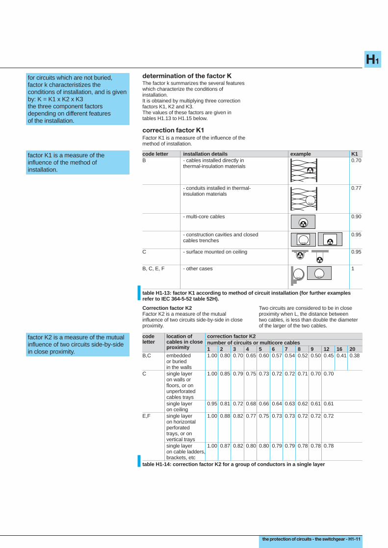
determination of the factor KThe factor k summarizes the several featureswhich characterize the conditions ofinstallation.It is obtained by multiplying three correctionfactors K1, K2 and K3.The values of these factors are given intables H1.13 to H1.15 below.
correction factor K1Factor K1 is a measure of the influence of themethod of installation.
code letter installation details example K1B - cables installed directly in 0.70
thermal-insulation materials
- conduits installed in thermal- 0.77insulation materials
- multi-core cables 0.90
- construction cavities and closed 0.95cables trenches
C - surface mounted on ceiling 0.95
B, C, E, F - other cases 1
factor K1 is a measure of theinfluence of the method ofinstallation.
table H1-13: factor K1 according to method of circuit installation (for further examplesrefer to IEC 364-5-52 table 52H).
Correction factor K2Factor K2 is a measure of the mutualinfluence of two circuits side-by-side in closeproximity.
Two circuits are considered to be in closeproximity when L, the distance betweentwo cables, is less than double the diameterof the larger of the two cables.
factor K2 is a measure of the mutualinfluence of two circuits side-by-sidein close proximity.
code location of correction factor K2letter cables in close number of circuits or multicore cables
proximity 1 2 3 4 5 6 7 8 9 12 16 20B,C embedded 1.00 0.80 0.70 0.65 0.60 0.57 0.54 0.52 0.50 0.45 0.41 0.38
or buriedin the walls
C single layer 1.00 0.85 0.79 0.75 0.73 0.72 0.72 0.71 0.70 0.70on walls orfloors, or onunperforatedcables trayssingle layer 0.95 0.81 0.72 0.68 0.66 0.64 0.63 0.62 0.61 0.61on ceiling
E,F single layer 1.00 0.88 0.82 0.77 0.75 0.73 0.73 0.72 0.72 0.72on horizontalperforatedtrays, or onvertical trayssingle layer 1.00 0.87 0.82 0.80 0.80 0.79 0.79 0.78 0.78 0.78on cable ladders,brackets, etc
table H1-14: correction factor K2 for a group of conductors in a single layer
H1-12 - the protection of circuits - the switchgear
H1
2. practical method for determining the smallest allowablecross-sectional-area of circuit conductors (continued)
2.2 determination of conductor size for unburied circuits (continued)
When cables are installed in more than onelayer a further factor, by which K2 must bemultiplied, will have the following values :2 layers : 0.803 layers : 0.734 or 5 layers : 0.70.
Correction factor K3Factor K3 is a measure of the influence of thetemperature, according to the type ofinsulation.
ambient insulationtemperatures elastomer polyvinylchloride cross-linked-
(rubber) (PVC) polyethylene (XLPE)butyl, ethylene-propylene-rubber (EPR)
10 1.29 1.22 1.1515 1.22 1.17 1.1220 1.15 1.12 1.0825 1.07 1.07 1.0430 1.00 1.00 1.0035 0.93 0.93 0.9640 0.82 0.87 0.9145 0.71 0.79 0.8750 0.58 0.71 0.8255 - 0.61 0.7660 - 0.50 0.7165 - - 0.6570 - - 0.5875 - - -80 - - -
factor K3 is a measure of theinfluence of the temperatureaccording to the type of insulation.
table H1-15: correction factor K3 for ambient temperatures other than 30 °C.
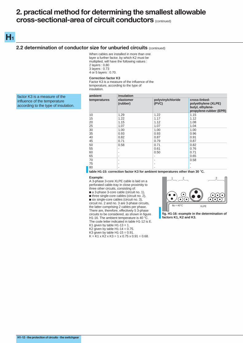
Example:A 3-phase 3-core XLPE cable is laid on aperforated cable-tray in close proximity tothree other circuits, consisting of:c a 3-phase 3-core cable (circuit no. 1),c three single-core cables (circuit no. 2),c six single-core cables (circuit no. 3),circuit no. 2 and no. 3 are 3-phase circuits,the latter comprising 2 cables per phase.There are, therefore, effectively 5 3-phasecircuits to be considered, as shown in figureH1-16. The ambient temperature is 40 °C.The code letter indicated in table H1-12 is E.K1 given by table H1-13 = 1.K2 given by table H1-14 = 0.75.K3 given by table H1-15 = 0.91.K = K1 x K2 x K3 = 1 x 0.75 x 0.91 = 0.68.
1 2 3
θa = 40°C XLPE
fig. H1-16: example in the determination offactors K1, K2 and K3.
the protection of circuits - the switchgear - H1-13
H1
insulation and number of conductors (2 or 3)rubber butyl or XLPE or EPRor PVC
code B PVC3 PVC2 PR3 PR2 B codeletter C PVC3 PVC2 PR3 PR2 C letter
E PVC3 PVC2 PR3 PR2 EF PVC3 PVC2 PR3 PR2 F
c.s.a. 1.5 15.5 17.5 18.5 19.5 22 23 24 26 1.5 c.s.a.copper 2.5 21 24 25 27 30 31 33 36 2.5 copper(mm2) 4 28 32 34 36 40 42 45 49 4 (mm2)
6 36 41 43 48 51 54 58 63 610 50 57 60 63 70 75 80 86 1016 68 76 80 85 94 100 107 115 1625 89 96 101 112 119 127 138 149 161 2535 110 119 126 138 147 158 169 185 200 3550 134 144 153 168 179 192 207 225 242 5070 171 184 196 213 229 246 268 289 310 7095 207 223 238 258 278 298 328 352 377 95120 239 259 276 299 322 346 382 410 437 120150 299 319 344 371 395 441 473 504 150185 341 364 392 424 450 506 542 575 185240 403 430 461 500 538 599 641 679 240300 464 497 530 576 621 693 741 783 300400 656 754 825 940 400500 749 868 946 1083 500630 855 1005 1088 1254 630
c.s.a. 2.5 16.5 18.5 19.5 21 23 25 26 28 2.5 c.s.a.aluminium 4 22 25 26 28 31 33 35 38 4 alu(mm2) 6 28 32 33 36 39 43 45 49 6 (mm2)
10 39 44 46 49 54 59 62 67 1016 53 59 61 66 73 79 84 91 1625 70 73 78 83 90 98 101 108 121 2535 86 90 96 103 112 122 126 135 150 3550 104 110 117 125 136 149 154 164 184 5070 133 140 150 160 174 192 198 211 237 7095 161 170 183 195 211 235 241 257 289 95120 186 197 212 226 245 273 280 300 337 120150 227 245 261 283 316 324 346 389 150185 259 280 298 323 363 371 397 447 185240 305 330 352 382 430 439 470 530 240300 351 381 406 440 497 508 543 613 300400 526 600 663 740 400500 610 694 770 856 500630 711 808 899 996 630
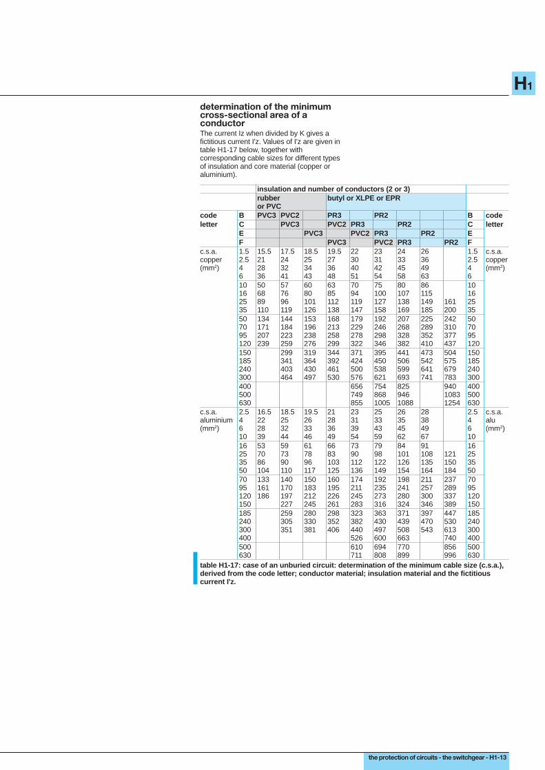
determination of the minimumcross-sectional area of aconductorThe current Iz when divided by K gives afictitious current I'z. Values of I'z are given intable H1-17 below, together withcorresponding cable sizes for different typesof insulation and core material (copper oraluminium).
table H1-17: case of an unburied circuit: determination of the minimum cable size (c.s.a.),derived from the code letter; conductor material; insulation material and the fictitiouscurrent I'z.

H1-14 - the protection of circuits - the switchgear
H1
2. practical method for determining the smallest allowablecross-sectional-area of circuit conductors (continued)
2.2 determination of conductor size for unburied circuits (continued)
ExampleThe example shown in figure H1-16 fordetermining the value of K, will also be usedto illustrate the way in which the minimumcross-sectional-area (c.s.a.) of conductorsmay be found, by using the table H1-17.The XLPE cable to be installed will carry23 amps per phase.Previous examples show that:c the appropriate code letter is E,c the factor K = 0.68.
1 2 3
θa = 40°C XLPE
fig. H1-18: example for the determinationof minimum cable sizes.
Determination of the cross-sectional areasA standard value of In nearest to, but higherthan 23 A is required.Two solutions are possible, one based onprotection by a circuit breaker and the secondon protection by fuses.c circuit breaker: In = 25 Av permissible current Iz = 25 Av fictitious current
I'z = 25 = 36.8 A 0.68v cross-sectional-area of conductors is foundas follows:In the column PR3 corresponding to codeletter E the value of 42 A (the nearest valuegreater than 36.8 A) is shown to require acopper conductor c.s.a. of 4 mm2.For an aluminium conductor thecorresponding values are 43 A and 6 mm2.c fuses: In = 25 Av permissible current Iz = K3In = 1.21 x 25 = Iz = 30.3 A
v the fictitious current I'z = 30.3 = 40.6 A 0.68
v the cross-sectional-areas, of copper oraluminium conductors are (in this case) foundto be the same as those noted above for acircuit-breaker-protected circuit.
2.3 determination of conductor size for buried circuitsIn the case of buried circuits thedetermination of minimum conductor sizes,necessitates the establishement of a factor K.
A code letter corresponding to a method ofinstallation is not necessary.
determination of factor KFactor K summarizes the global influence ofdifferent conditions of installation, and isobtained by multiplying together correctionfactors K4, K5, K6 and K7.The values of these several factors are givenin tables H1-19 to H1-22.
Correction factor K4Factor K4 is a measure of the influence of themethod of installation.
for buried circuits the value of factorK characteristizes the conditions ofinstallation, and is obtained from thefollowing factors:K4 x K5 x K6 x K7 = Keach of which depends on aparticular feature of installation.
method of installation K4placed in earthenware ducts; in 0.8conduits, or in decorative mouldingsother cases 1table H1-19: correction factor K4 related tothe method of installation.
factor K4 measures the influence ofthe method of installation.
Correction factor K5Factor K5 is a measure of the mutualinfluence of circuits placed side-by-side inclose proximity.Cables are in close proximity when thedistance L separating them is less thandouble the diameter of the larger of the twocables concerned.
factor K5 measures the mutualinfluence of circuits placed side-by-side in close proximity.
location of correction factor K5cables side-by-side number of circuits or of multicore cablesin close proximity 1 2 3 4 5 6 7 8 9 12 16 20buried 1.00 0.80 0.70 0.65 0.60 0.57 0.54 0.52 0.50 0.45 0.41 0.38table H1-20: correction factor K5 for the grouping of several circuits in one layer.
When cables are laid in several layers,multiply K5 by 0.8 for 2 layers, 0.73 for3 layers, 0.7 for 4 layers or 5 layers.
the protection of circuits - the switchgear - H1-15
H1
factor K6 is a measure of theinfluence of the earth in which thecable is buried.
Correction factor K6This factor takes into account the nature andcondition of the soil in which a cable (orcables) is (are) buried; notably its thermalconductivity.
nature of soil K6very wet soil (saturated) 1.21wet soil 1.13damp soil 1.05dry soil 1.00very dry soil (sunbaked) 0.86table H1-21: correction factor K6 for thenature of the soil.
factor K7 is a measure of theinfluence of the soil temperature.
Correction factor K7This factor takes into account the influence ofsoil temperature if it differs from 20 °C.
soil temperature insulation°C polyvinyl-chloride cross-linked polyethylene
(PVC) (XLPE)ethylene-propylenerubber (EPR)
10 1.10 1.0715 1.05 1.0420 1.00 1.0025 0.95 0.9630 0.89 0.9335 0.84 0.8940 0.77 0.8545 0.71 0.8050 0.63 0.7655 0.55 0.7160 0.45 0.65table H1-22: correction factor K7 for soil temperatures different than 20 °C.
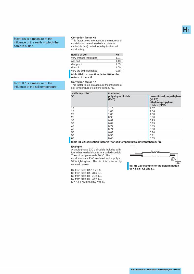
ExampleA single-phase 230 V circuit is included withfour other loaded circuits in a buried conduit.The soil temperature is 20 °C. Theconductors are PVC insulated and supply a5 kW lighting load. The circuit is protected bya circuit breaker.
K4 from table H1-19 = 0.8.K5 from table H1- 20 = 0.6.K6 from table H1- 21 = 1.0.K7 from table H1- 22 = 1.0.K = K4 x K5 x K6 x K7 = 0.48.
5 kW230 V
θa = 20°C
fig. H1-23: example for the determinationof K4, K5, K6 and K7.

H1-16 - the protection of circuits - the switchgear
H1
2. practical method for determining the smallest allowablecross-sectional-area of circuit conductors (continued)
2.3 determination of conductor size for buried circuits (continued)
determination of the smallestc.s.a. (cross-sectional-area) of aconductor, for buried circuitsKnowing Iz and K, the corresponding cross-sectional-areas are given in table H1-24below.
insulation and number of loaded conductorsrubber or PVC Butyl, or cross-linked polyethylene
XLPE, or ethylene-propylene rubberEPR
3 conductors 2 conductors 3 conductors 2 conductorsc.s.a. 1.5 26 32 31 37copper 2.5 34 42 41 48(mm2) 4 44 54 53 63
6 56 67 66 8010 74 90 87 10416 96 116 113 13625 123 148 144 17335 147 178 174 20850 174 211 206 24770 216 261 254 30495 256 308 301 360120 290 351 343 410150 328 397 387 463185 367 445 434 518240 424 514 501 598300 480 581 565 677
c.s.a. 10 57 68 67 80aluminium 16 74 88 87 104(mm2) 25 94 114 111 133
35 114 137 134 16050 134 161 160 18870 167 200 197 23395 197 237 234 275120 224 270 266 314150 254 304 300 359185 285 343 337 398240 328 396 388 458300 371 447 440 520
table H1-24: case of a buried circuit: minimum c.s.a. in terms of type of conductor; type ofinsulation; and value of fictitious current I'z (I'z = Iz).
K
ExampleThis is a continuation of the previousexample, for which the factors K4, K5, K6and K7 were determined, and the factor Kwas found to be 0.48.
Full load current
IB = 5.000 = 22 A 230
Selection of protectionA circuit-breaker rated at 25 A would beappropriate.
Maximum permanent current permittedIz = 25 A (i.e. the circuit-breaker rating In)
Fictitious current
I'z = Iz = 25 = 52.1 A K 0.48
C.s.a. of circuit conductorsIn the column PVC, 2 conductors, a current of54 A corresponds to a 4 mm2 copperconductor.In the case where the circuit conductors arein aluminium, the same fictitious current(52 A) would require the choice of 10 mm2
corresponding to a fictitious current value(for aluminium) of 68 A.
5 kW230 V
θa = 20°C
fig. H1-25: example for determination ofthe minimum c.s.a. of the circuitconductors.

the protection of circuits - the switchgear - H1-17
H1
3. determination of voltage drop
The impedance of circuit conductors is lowbut not negligible: when carrying load currentthere is a fall in voltage between the origin ofthe circuit and the load terminals. The correctoperation of an item of load (a motor; lightingcircuit; etc.) depends on the voltage at itsterminals being maintained at a value close toits rated value. It is necessary therefore todimension the circuit conductors such, that atfull-load current, the load terminal voltage is
maintained within the limits required forcorrect performance.This section deals with methods ofdetermining voltage drops, in order to checkthat:c they conform to the particular standardsand regulations in force,c they can be tolerated by the load,c they satisfy the essential operationalrequirements.
3.1 maximum voltage-drop limitMaximum allowable voltage-drop limits varyfrom one country to another. Typical valuesfor LV installations are given below in tableH1-26.
maximum voltage-drop between the service-connection point and the point of utilizationlighting other uses
(heating and power)a low-voltage service connection from a LV 3 % 5 %public power distribution networkconsumers HV/LV substation supplied from 6 % 8 %a public distribution HV system
table H1-26: maximum voltage-drop limits.
These voltage-drop limits refer to normalsteady-state operating conditions and do notapply at times of motor starting; simultaneousswitching (by chance) of several loads, etc.as mentioned in Chapter B Sub-clause 4.3(factor of simultaneity, etc.).When voltage drops exceed the valuesshown in table H1-26 larger cables (wires)must be used to correct the condition.The value of 8%, while permitted, can lead toproblems for motor loads; for example:c in general, satisfactory motor performancerequires a voltage within ± 5% of its ratednominal value in steady-state operation,c starting current of a motor can be 5 to7 times its full-load value (or even higher). If8% voltage drop occurs at full-load current,then a drop of 40% or more will occur duringstart-up. In such conditions the motor willeither:v stall (i.e. remain stationary due toinsufficient torque to overcome the loadtorque) with consequent over-heating andeventual trip-out,v or accelerate very slowly, so that the heavycurrent loading (with possibly undesirablelow-voltage effects on other equipment) willcontinue beyond the normal start-up period;c finally an 8% voltage drop represents acontinuous (E2/R watts) of power loss, which,for continuous loads will be a significantwaste of (metered) energy. For these reasonsit is recommended that the maximum value of
8% in steady operating conditions should notbe reached on circuits which are sensitive tounder-voltage problems.
Important:In a number of countries the existing220/380 V 3-phase systems are beinguprated to operate eventually at nominal230/400 V (the recommended IEC standard).Transformer manufacturers in these countrieshave recently increased the no-loadsecondary voltage of their distributiontransformers accordingly, to 237/410 V.After several years of transition in theappliances industry, distribution transformerswill be manufactured with no-load ratios of242/420 V.The rated voltage of consumer appliances willevolve in the same time-scale.From now on, therefore, voltage-dropcalculations must take account of thesechanges.Dangerous possible consequences formotors are:c a lightly-loaded "new" transformer and an"old" motor: risk of overvoltage on the motor,c a fully-loaded "old" transformer and a "new"motor: risk of undervoltage at the motor.Similar (but inverse) problems will arise incountries which presently operate 240/415 Vsystems, if the IEC 230/400 V standard isadopted by them.
load
LV consumer
5%(1)
8%(1)
HV consumer
(1) between the LVsupply point andthe load
fig. H1-27: maximum voltage drop.
H1-18 - the protection of circuits - the switchgear
H1
circuit voltage drop ( ∆ U)in volts in %
single phase: phase/phase ∆U = 2 IB (R cos ϕ + X sin ϕ) L 100 ∆U Un
single phase: phase/neutral ∆U = 2 IB (R cos ϕ + X sin ϕ) L 100 ∆U Vn
balanced 3-phase: 3 phases ∆U = eIB (R cos ϕ + X sin ϕ) L 100 ∆U(with or without neutral) Un
3. determination of voltage drop (continued)
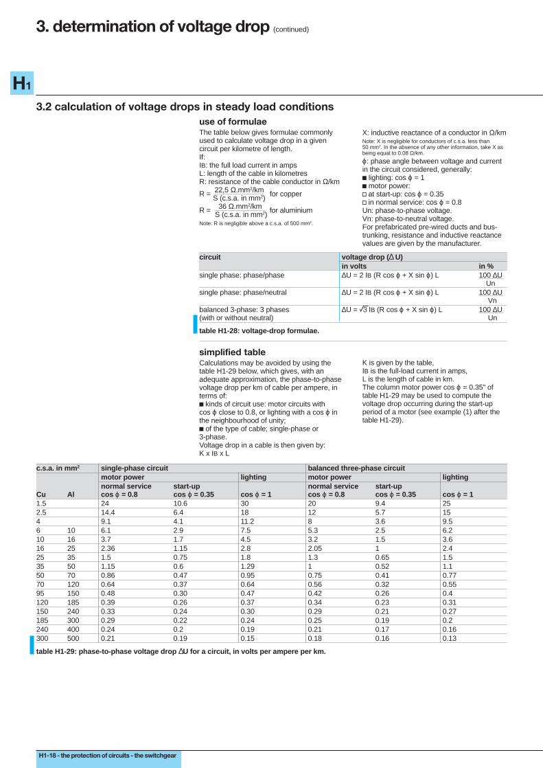
3.2 calculation of voltage drops in steady load conditionsuse of formulaeThe table below gives formulae commonlyused to calculate voltage drop in a givencircuit per kilometre of length.If:IB: the full load current in ampsL: length of the cable in kilometresR: resistance of the cable conductor in Ω/km
R = 22,5 Ω.mm2/km for copper S (c.s.a. in mm2)
R = 36 Ω.mm2/km for aluminium S (c.s.a. in mm2)Note: R is negligible above a c.s.a. of 500 mm2.
X: inductive reactance of a conductor in Ω/kmNote: X is negligible for conductors of c.s.a. less than50 mm2. In the absence of any other information, take X asbeing equal to 0.08 Ω/km.
ϕ: phase angle between voltage and currentin the circuit considered, generally:c lighting: cos ϕ = 1c motor power:v at start-up: cos ϕ = 0.35v in normal service: cos ϕ = 0.8Un: phase-to-phase voltage.Vn: phase-to-neutral voltage.For prefabricated pre-wired ducts and bus-trunking, resistance and inductive reactancevalues are given by the manufacturer.
table H1-28: voltage-drop formulae.
simplified tableCalculations may be avoided by using thetable H1-29 below, which gives, with anadequate approximation, the phase-to-phasevoltage drop per km of cable per ampere, interms of:c kinds of circuit use: motor circuits withcos ϕ close to 0.8, or lighting with a cos ϕ inthe neighbourhood of unity;c of the type of cable; single-phase or3-phase.Voltage drop in a cable is then given by:K x IB x L
K is given by the table,IB is the full-load current in amps,L is the length of cable in km.The column motor power cos ϕ = 0.35" oftable H1-29 may be used to compute thevoltage drop occurring during the start-upperiod of a motor (see example (1) after thetable H1-29).
c.s.a. in mm 2 single-phase circuit balanced three-phase circuitmotor power lighting motor power lightingnormal service start-up normal service start-up
Cu Al cos ϕ = 0.8 cos ϕ = 0.35 cos ϕ = 1 cos ϕ = 0.8 cos ϕ = 0.35 cos ϕ = 11.5 24 10.6 30 20 9.4 252.5 14.4 6.4 18 12 5.7 154 9.1 4.1 11.2 8 3.6 9.56 10 6.1 2.9 7.5 5.3 2.5 6.210 16 3.7 1.7 4.5 3.2 1.5 3.616 25 2.36 1.15 2.8 2.05 1 2.425 35 1.5 0.75 1.8 1.3 0.65 1.535 50 1.15 0.6 1.29 1 0.52 1.150 70 0.86 0.47 0.95 0.75 0.41 0.7770 120 0.64 0.37 0.64 0.56 0.32 0.5595 150 0.48 0.30 0.47 0.42 0.26 0.4120 185 0.39 0.26 0.37 0.34 0.23 0.31150 240 0.33 0.24 0.30 0.29 0.21 0.27185 300 0.29 0.22 0.24 0.25 0.19 0.2240 400 0.24 0.2 0.19 0.21 0.17 0.16300 500 0.21 0.19 0.15 0.18 0.16 0.13
table H1-29: phase-to-phase voltage drop ∆U for a circuit, in volts per ampere per km.

the protection of circuits - the switchgear - H1-19
H1
examples:Example 1 (figure H1-30)A three-phase 35 mm2 copper cable50 metres long supplies a 400 V motortaking:c 100 A at a cos ϕ = 0.8 on normalpermanent load;c 500 A (5 In) at a cos ϕ = 0.35 duringstart-up.The voltage drop at the origin of the motorcable in normal circumstances (i.e. with thedistribution board of figure H1-30 distributinga total of 1.000 A) is 10 V phase-to-phase.What is the volt drop at the motor terminals:c in normal service?c during start-up?
Solution:c voltage drop in normal service conditions:∆U % = 100 ∆U/UnTable H1-29 shows 1 V/A/km so that:∆U for the cable = 1 x 100 x 0.05 = 5 V∆U total = 10 + 5 = 15 V = i.e. 15 x 100 = 3.75 %400This value is less than that authorized (8%)and is satisfactory.c voltage drop during motor start-up:∆U cable = 0.52 x 500 x 0.05 = 13 VOwing to the additional current taken by themotor when starting, the volt drop at thedistribution board will exceed 10 Volts.Supposing that the infeed to the distributionboard during motor starting is 900 + 500 =1.400 A then the volt-drop at the distributionboard will increase approximately pro rata,i.e.10 x 1400 = 14 V 1000∆U distribution board = 14 V∆U for the motor cable = 13 V∆U total = 13 + 14 = 27 V i.e.27 x 100 = 6.75 % 400a value which is satisfactory during motorstarting.
1000 A
400 V
50 m / 35 mm2 CuIB = 100 A(500 A duringstart-up)
fig. H1-30: example 1.
50 m / 70 mm2 CuIB = 150 A
20 m / 2.5 mm2 CuIB = 20 A
fig. H1-31: example 2.
Example 2A 3-phase 4-wire copper line of 70 mm2 c.s.a.and a length of 50 m passes a current of150 A. The line supplies, among other loads,3 single-phase lighting circuits, each of2.5 mm2 c.s.a. copper 20 m long, and eachpassing 20 A.It is assumed that the currents in the 70 mm2
line are balanced and that the three lightingcircuits are all connected to it at the samepoint.What is the voltage drop at the end of thelighting circuits?
Solution:c voltage drop in the 4-wire line:∆U % = 100 ∆U/UnTable H1-29 shows 0.55 V/A/km.∆U line = 0.55 x 150 x 0.05 = 4.125 Vphase-to-phase
which: 4.125 V = 2.38 V phase to neutral. ec voltage drop in any one of the lightingsingle-phase circuits:∆U for a single-phase circuit = 18 x 20 x 0.02= 7.2 VThe total volt-drop is therefore7.2 + 2.38 = 9.6 V 9.6 V x 100 = 4.2 %230 VThis value is satisfactory, being less than themaximum permitted voltage drop of 6%.
H1-20 - the protection of circuits - the switchgear
H1
4. short-circuit current calculations
knowing the levels of 3-phasesymmetrical short-circuit currents(Isc) at different points in aninstallation is an essential feature ofits design.
A knowledge of 3-phase symmetrical short-circuit current values (Isc) at strategic pointsof an installation is necessary in order todimension switchgear (fault current rating);cables (thermal withstand rating); protectivedevices (discriminative trip settings) and soon...In the following notes a 3-phase short-circuitof zero impedance (the so-called boltedshort-circuit) fed through a typical HV/LVdistribution transformer will be examined.
Except in very unusual circumstances, thistype of fault is the most severe, and iscertainly the simplest to calculate.Short-circuit currents occurring in a networksupplied from an alternator and also in d.c.systems are dealt with in Chapter JSub-clauses 1.1 and 6.1.The simplified calculations and practical ruleswhich follow give conservative results ofsufficient accuracy, in the large majority ofcases, for installation design purposes.
4.1 short-circuit current at the secondary terminals of a HV/LV distribution transformerthe case of one transformerc as a first approximation the impedance ofthe HV system is assumed to be negligiblysmall, so that:
Isc = In x 100 where Usc
In = P x 103 and: eU20P = kVA rating of the transformer,U20 = phase-to-phase secondary volts onopen circuit,In = nominal current in ampsIsc = short-circuit fault current in amps,Usc = short-circuit impedance voltage of thetransformer in %.Typical values of Usc for distributiontransformers are given in the table H1-32.
Example:400 kVA transformer, 242/420 V at no loadUsc = 4%
In = 400 x 103 = 550 A ÷ ex 420
Isc = 550 x 100 = 13.75 kA 4c in practice Isc is slightly less than thatcalculated by this method, as shown in thefollowing table (H1-33) since the HV systemimpedance is such that its fault level at theHV terminals of the transformer rarelyexceeds 500 MVA. A level of 250 MVA, orless, is more common.
transformer Usc in %rating type of transformer
oil-immersed cast-resin50 to 630 4% 6%800 to 2500 6% 6%
table H1-32: typical values of Usc fordifferent kVA ratings of transformers withHV windings iiiii 20 kV.
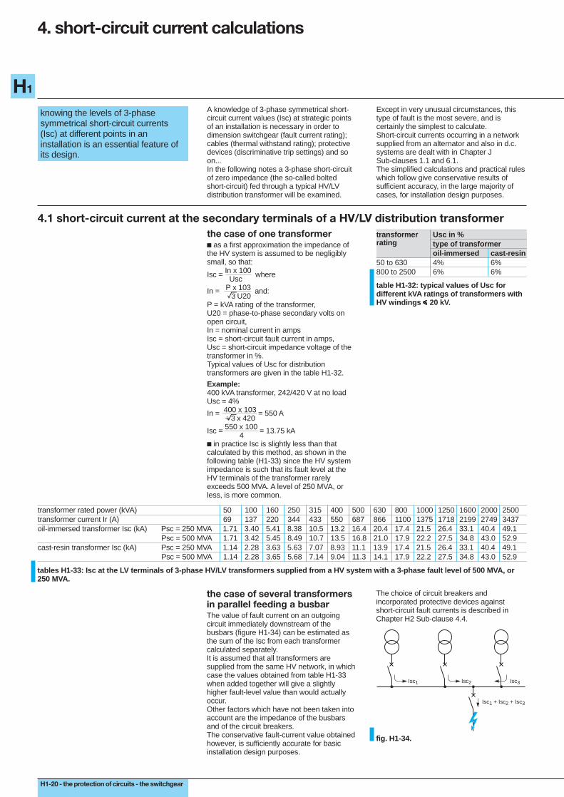
the case of several transformersin parallel feeding a busbarThe value of fault current on an outgoingcircuit immediately downstream of thebusbars (figure H1-34) can be estimated asthe sum of the Isc from each transformercalculated separately.It is assumed that all transformers aresupplied from the same HV network, in whichcase the values obtained from table H1-33when added together will give a slightlyhigher fault-level value than would actuallyoccur.Other factors which have not been taken intoaccount are the impedance of the busbarsand of the circuit breakers.The conservative fault-current value obtainedhowever, is sufficiently accurate for basicinstallation design purposes.
tables H1-33: Isc at the LV terminals of 3-phase HV/LV transformers supplied from a HV system with a 3-phase fault level of 500 MVA, or250 MVA.
The choice of circuit breakers andincorporated protective devices againstshort-circuit fault currents is described inChapter H2 Sub-clause 4.4.
Isc1 Isc3Isc2
Isc1 + Isc2 + Isc3
fig. H1-34.
transformer rated power (kVA) 50 100 160 250 315 400 500 630 800 1000 1250 1600 2000 2500transformer current Ir (A) 69 137 220 344 433 550 687 866 1100 1375 1718 2199 2749 3437oil-immersed transformer Isc (kA) Psc = 250 MVA 1.71 3.40 5.41 8.38 10.5 13.2 16.4 20.4 17.4 21.5 26.4 33.1 40.4 49.1
Psc = 500 MVA 1.71 3.42 5.45 8.49 10.7 13.5 16.8 21.0 17.9 22.2 27.5 34.8 43.0 52.9cast-resin transformer Isc (kA) Psc = 250 MVA 1.14 2.28 3.63 5.63 7.07 8.93 11.1 13.9 17.4 21.5 26.4 33.1 40.4 49.1
Psc = 500 MVA 1.14 2.28 3.65 5.68 7.14 9.04 11.3 14.1 17.9 22.2 27.5 34.8 43.0 52.9
the protection of circuits - the switchgear - H1-21
H1
4.2 3-phase short-circuit current (Isc) at any point within a LV installationIn a 3-phase installation Isc at any point isgiven by:
Isc = U20 (amps) eZTU20 = phase-to-phase voltage of the open-circuited secondary windings of the power-supply transformer(s).ZT = total impedance per phase of theinstallation upstream of the fault location(in ohms).
method of calculating ZTEach component of an installation (HVnetwork, transformer, cable, circuit breaker,busbar, and so on...) is characterized by itsimpedance Z, comprising an element ofresistance (R) and an inductive reactance(X). It may be noted that capacitivereactances are not important in short-circuitcurrent calculations.The parameters R, X and Z are expressed inohms, and are related by the sides of a right-angled triangle, as shown in the impedancediagram of figure H1-35.The method consists in dividing the networkinto convenient sections, and to calculate theR and X values for each.Where sections are connected in series in thenetwork all the resistive elements in thesection are added arithmetically; likewise forthe reactances, to give RT and XT. Theimpedance (Z) for the combined sectionsconcerned is then calculated from
Z R XT TT = +2 2
Any two sections of the network which areconnected in parallel, can, if, predominantlyboth resistive (or both inductive) be combinedto give a single equivalent resistance (orreactance) as follows:Let R1 and R2 be the two resistancesconnected in parallel, then the equivalentresistance R3 wil be given by:
R3 = R1 R2 or for reactances X3 = X1 X2 R1 + R2 X1 + X2Combining two or more dissimilar circuits inparallel is (fortunately) seldom required innormal radial-type installation networks andwill not be demonstrated in the main text.General methods for reducing impedances toa single equivalent impedance are given,however, in Appendix H1.
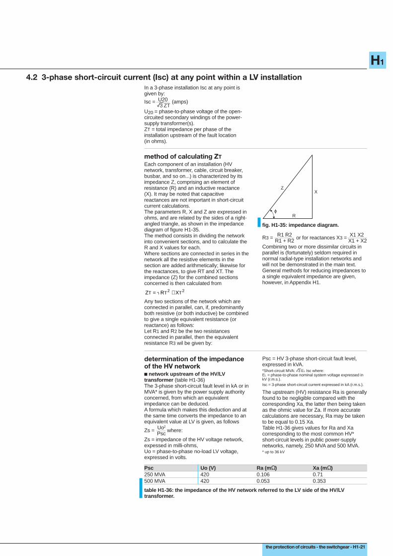
ZX
Rϕ
fig. H1-35: impedance diagram.
determination of the impedanceof the HV networkc network upstream of the HV/LVtransformer (table H1-36)The 3-phase short-circuit fault level in kA or inMVA* is given by the power supply authorityconcerned, from which an equivalentimpedance can be deduced.A formula which makes this deduction and atthe same time converts the impedance to anequivalent value at LV is given, as follows
Zs = Uo2 where: PscZs = impedance of the HV voltage network,expessed in milli-ohms,Uo = phase-to-phase no-load LV voltage,expressed in volts.
Psc = HV 3-phase short-circuit fault level,expressed in kVA.*Short-circuit MVA: eEL Isc where:EL = phase-to-phase nominal system voltage expressed inkV (r.m.s.).Isc = 3-phase short-circuit current expressed in kA (r.m.s.).
The upstream (HV) resistance Ra is generallyfound to be negligible compared with thecorresponding Xa, the latter then being takenas the ohmic value for Za. If more accuratecalculations are necessary, Ra may be takento be equal to 0.15 Xa.Table H1-36 gives values for Ra and Xacorresponding to the most common HV*short-circuit levels in public power-supplynetworks, namely, 250 MVA and 500 MVA.* up to 36 kV
Psc Uo (V) Ra (m Ω) Xa (mΩ)250 MVA 420 0.106 0.71500 MVA 420 0.053 0.353
table H1-36: the impedance of the HV network referred to the LV side of the HV/LVtransformer.
H1-22 - the protection of circuits - the switchgear
H1
4. short-circuit current calculations (continued)
4.2. 3-phase short-circuit current (Isc) at any point within a LV installation (continued)
c transformers (table H1-37)The impedance Ztr of a transformer, viewedfrom the LV terminals, is given by the formula:
Ztr = U
22
O x
Usc milli-ohms where:
Pn 100U2 o = open-circuit secondary phase-to-phase voltage expressed in volts.Pn = rating of the transformer (in kVA).Usc = the short-circuit impedance voltage ofthe transformer expressed in %.The transformer windings resistance Rtr canbe derived from the total losses as follows:
Pcu = 3 In2 Rtr so that Rtr = Pcu x 103
3 In2
in milli-ohms wherePcu = total losses in watts.In = nominal full-load current in amps.Rtr = resistance of one phase of thetransformer in milli-ohms (the LV andcorresponding HV winding for one LV phaseare included in this resistance value).
For an approximate calculation Rtr may beignored since X ≈ Z in standard distribution-type transformers.
table H1-37: resistance, reactance and impedance values for typical distribution transformers with HV windings iiiii 20 kV.
c circuit breakersIn LV circuits, the impedance of circuitbreakers upstream of the fault location mustbe taken into account. The reactance valueconventionally assumed is 0.15 mΩ per CB,while the resistance is neglected.
c busbarsThe resistance of busbars is generallynegligible, so that the impedance ispractically all reactive, and amounts toapproximately 0.15 mΩ/metre* length for LVbusbars (doubling the spacing between thebars increases the reactance by about 10%only).* for 50 Hz systems, but 0.18 mΩ/metre length at 60 Hz.
c circuit conductorsThe resistance of a conductor is given by theformula:
Rc = ρ x L where Sρ = the resistivity constant of the conductormaterial at the normal operating temperaturebeing:22.5 mΩ.mm2/m for copper,36 mΩ.mm2/m for aluminium,S = c.s.a. of conductor in mm2.Cable reactance values can be obtained fromthe manufacturers. For c.s.a. of less than50 mm2 reactance may be ignored. In theabsence of other information, a value of0.08 mΩ/metre may be used (for 50 Hzsystems) or 0.096 mΩ/metre (for 60 Hzsystems). For prefabricated bus-trunking andsimilar pre-wired ducting systems, themanufacturer should be consulted.
c motorsAt the instant of short-circuit, a running motorwill act (for a brief period) as a generator, andfeed current into the fault.In general, this fault-current contribution maybe ignored. However, for more precisecalculation, particularly in the case of largemotors and/or numerous smaller motors, thetotal contribution can be estimated from theformula:Iscm = 3.5 In from each motori.e. 3.5 m In for m similar motors operatingconcurrently.The motors concerned will be the 3-phasemotors only; single-phase-motor contributionbeing insignificant.For HV circuit breakers, the contribution frommotors is often reduced to very low values atthe instant of contact separation, and for thatreason is frequently ignored, but with low-inertia high-speed LV CBs* the value given inthe above formula is recommended.Note: for circuit breaker fault-current making-duty however, no account can be taken ofdiminution of fault current contribution, andeach running motor will initially feed currentinto the fault at a level approaching its ownstarting current, i.e. 4 or 5 In.* and fuses
c fault-arc resistanceShort-circuit faults generally form an arcwhich has the properties of resistance. Theresistance is not stable and its average valueis low, but at low voltage this resistance issufficient to reduce the fault-current to someextent. Experience has shown that areduction of the order of 20% may beexpected. This phenomenon will effectivelyease the current-breaking duty of a CB, butaffords no relief for its fault-current makingduty.
transformer rated power kVA 50 100 160 250 315 400 500 630 800 1000 1250 1600 2000 2500oil-immersed transformer Usc % 4 4 4 4 4 4 4 4 6 6 6 6 6 6
Rtr mΩ 95.3 37.9 16.2 9.2 6.9 5.1 3.9 2.9 2.9 2.3 1.8 1.4 1.1 0.9Xtr mΩ 104.1 59.5 41.0 26.7 21.3 16.9 13.6 10.8 12.9 10.3 8.3 6.5 5.2 4.1Ztr mΩ 141.1 70.5 44.1 28.2 22.4 17.7 14.1 11.2 13.2 10.6 8.5 6.6 5.3 4.2
cast-resin transformer Usc % 6 6 6 6 6 6 6 6 6 6 6 6 6Rtr mΩ 33.5 18.6 10.7 8.2 6.1 4.6 3.5 2.6 1.9 1.5 1.1 0.8 0.6Xtr mΩ 100.4 63.5 41.0 32.6 25.8 20.7 16.4 13.0 10.4 8.3 6.5 5.2 4.2Ztr mΩ 105.8 66.2 42.4 33.6 26.5 21.2 16.8 13.3 10.6 8.4 6.6 5.3 4.2
Xtr Ztr Rtr= −2 2
the protection of circuits - the switchgear - H1-23
H1
system elements considered resistance R in milli-ohms reactance X in milli-ohmssupply network Ra ≈ 0,15 Xa ≈ Za =
U22 0
table H1-33 Xa PscR can therefore be neglected in comparison with X
transformer Rtr = Pcu x 103
table H1-34 3In2
Rtr = is often negligible compared to Xtr avec Ztr = U22 0 x
Uscfor transformers > 100 kVA Pn 100
circuit breaker negligible XD = 0.15 mΩ/polebusbars negligible for S > 200 mm2 in the formula XB = 0.15 mΩ/m
below:
R = ρ L (1) S
circuit conductors (2) R = ρ L (1) cables : Xc = 0.08 mΩ/m S
motors see Sub-clause 4.2 "motors"(often negligible at LV))
three-phase short-circuit current in kA
Ztr Rtr−2 2
recapitulation table
M
3=Isc
RT2 + XT2
U2o
table H1-38: recapitulation table of impedances for different parts of a power-supply system.
U20: phase-to-phase no-load secondaryvoltage of HV/LV transformer (in volts).Psc: 3-phase short-circuit power at HVterminals of the HV/LV transformers (in kVA).Pcu: 3-phase total losses of the HV/LVtransformer (in watts).Pn: rating of the HV/LV transformer (in kVA).Usc: short-circuit impedance voltage of theHV/LV transfomer (in %).
RT : total resistance. XT: total reactance(1) ρ = resistivity at normal temperature ofconductors in serviceρ = 22.5 milli-ohms x mm2/metre for copperρ = 36 milli-ohms x mm2/metre for aluminium.(2) If there are several conductors in parallelper phase, then divide the resistance of oneconductor by the number of conductors. Thereactance remains practically unchanged.
R (mΩ) X (mΩ) RT (mΩ) XT (mΩ)
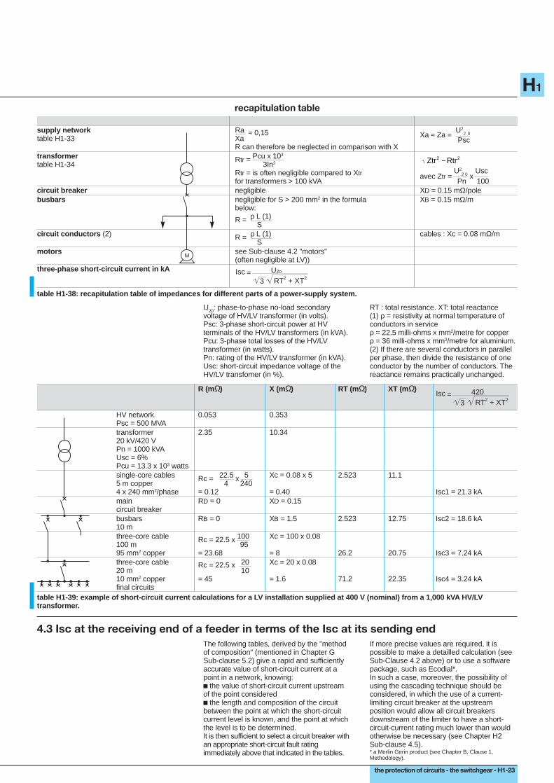
HV network 0.053 0.353Psc = 500 MVAtransformer 2.35 10.3420 kV/420 VPn = 1000 kVAUsc = 6%Pcu = 13.3 x 10³ wattssingle-core cables Rc = 22.5 x 5 Xc = 0.08 x 5 2.523 11.15 m copper 4 2404 x 240 mm2/phase = 0.12 = 0.40 Isc1 = 21.3 kAmain RD = 0 XD = 0.15circuit breakerbusbars RB = 0 XB = 1.5 2.523 12.75 Isc2 = 18.6 kA10 mthree-core cable Rc = 22.5 x 100 Xc = 100 x 0.08100 m 9595 mm2 copper = 23.68 = 8 26.2 20.75 Isc3 = 7.24 kAthree-core cable Rc = 22.5 x 20 Xc = 20 x 0.0820 m 1010 mm2 copper = 45 = 1.6 71.2 22.35 Isc4 = 3.24 kAfinal circuits
3=Isc
RT2 + XT2
420
table H1-39: example of short-circuit current calculations for a LV installation supplied at 400 V (nominal) from a 1,000 kVA H V/LVtransformer.
4.3 Isc at the receiving end of a feeder in terms of the Isc at its sending endThe following tables, derived by the "methodof composition" (mentioned in Chapter GSub-clause 5.2) give a rapid and sufficientlyaccurate value of short-circuit current at apoint in a network, knowing:c the value of short-circuit current upstreamof the point consideredc the length and composition of the circuitbetween the point at which the short-circuitcurrent level is known, and the point at whichthe level is to be determined.It is then sufficient to select a circuit breaker withan appropriate short-circuit fault ratingimmediately above that indicated in the tables.
If more precise values are required, it ispossible to make a detailled calculation (seeSub-Clause 4.2 above) or to use a softwarepackage, such as Ecodial*.In such a case, moreover, the possibility ofusing the cascading technique should beconsidered, in which the use of a current-limiting circuit breaker at the upstreamposition would allow all circuit breakersdownstream of the limiter to have a short-circuit-current rating much lower than wouldotherwise be necessary (see Chapter H2Sub-clause 4.5).* a Merlin Gerin product (see Chapter B, Clause 1,Methodology).

H1-24 - the protection of circuits - the switchgear
H1
4. short-circuit current calculations (continued)
4.3 Isc at the receiving end of a feeder in terms of the Isc at its sending end (continued)
copper c.s.a. of length of circuit (in metres)230 V / phase400 V conductors
(in mm 2)1.5 0.8 1 1.3 1.6 32.5 1 1.3 1.6 2.1 2.6 54 0.8 1.7 2.1 2.5 3.5 4 8.56 1.3 2.5 3 4 5 6.5 1310 0.8 1.1 2.1 4 5.5 6.5 8.5 11 2116 0.9 1 1.4 1.7 3.5 7 8.5 10 14 17 3425 1 1.3 1.6 2.1 2.6 5 10 13 16 21 26 5035 1.5 1.9 2.2 3 3.5 7.5 15 19 22 30 37 7550 1.1 2.1 2.7 3 4 5.5 11 21 27 32 40 55 11070 1.5 3 3.5 4.5 6 7.5 15 30 37 44 60 75 15095 0.9 1 2 4 5 6 8 10 20 40 50 60 80 100 200120 0.9 1 1.1 1.3 2.5 5 6.5 7.5 10 13 25 50 65 75 100 130 250150 0.8 1 1.1 1.2 1.4 2.7 5.5 7 8 11 14 27 55 70 80 110 140 270185 1 1.1 1.3 1.5 1.6 3 6.5 8 9.5 13 16 32 65 80 95 130 160 320240 1.2 1.4 1.6 1.8 2 4 8 10 12 16 20 40 80 100 120 160 200 400300 1.5 1.7 1.9 2.2 2.4 5 9.5 12 15 19 24 49 95 120 150 190 2402 x 120 1.5 1.8 2 2.3 2.5 5.1 10 13 15 20 25 50 100 130 150 200 2502 x 150 1.7 1.9 2.2 2.5 2.8 5.5 11 14 17 22 28 55 110 140 170 220 2802 x 185 2 2.3 2.6 2.9 3.5 6.5 13 16 20 26 33 65 130 160 200 260 3303 x 120 2.3 2.7 3 3.5 4 7.5 15 19 23 30 38 75 150 190 230 300 3803 x 150 2.5 2.9 3.5 3.5 4 8 16 21 25 33 41 80 160 210 250 330 4103 x 185 2.9 3.5 4 4.5 5 9.5 20 24 29 39 49 95 190 240 290 390Isc upstream Isc downstream(in kA) (in Ka)100 94 94 93 92 91 83 71 67 63 56 50 33 20 17 14 11 9 590 85 85 84 83 83 76 66 62 58 52 47 32 20 16 14 11 9 4.580 76 76 75 75 74 69 61 57 54 49 44 31 19 16 14 11 9 4.570 67 67 66 66 65 61 55 52 49 45 41 29 18 16 14 11 5 4.560 58 58 57 57 57 54 48 46 44 41 38 27 18 15 13 10 8.5 4.550 49 48 48 48 48 46 42 40 39 36 33 25 17 14 13 10 8.5 4.540 39 39 39 39 39 37 35 33 32 30 29 22 15 13 12 9.5 8 4.535 34 34 34 34 34 33 31 30 29 27 26 21 15 13 11 9 8 4.530 30 29 29 29 29 28 27 26 25 24 23 19 14 12 11 9 7.5 4.525 25 25 25 24 24 24 23 22 22 21 20 17 13 11 10 8.5 7 420 20 20 20 20 20 19 19 18 18 17 17 14 11 10 9 7.5 6.5 415 15 15 15 15 15 15 14 14 14 13 13 12 9.5 8.5 8 7 6 410 10 10 10 10 10 10 9.5 9.5 9.5 9.5 9 8.5 7 6.5 6.5 5.5 5 3.57 7 7 7 7 7 7 7 7 6.5 6.5 6.5 6 5.5 5 5 4.5 4 2.95 5 5 5 5 5 5 5 5 5 5 5 4.5 4 4 4 3.5 3.5 2.54 4 4 4 4 4 4 4 4 4 4 4 3.5 3.5 3.5 3 3 2.9 2.23 3 3 3 3 3 3 3 3 2.9 2.9 2.9 2.8 2.7 2.6 2.5 2.4 2.3 1.92 2 2 2 2 2 2 2 2 2 2 2 1.9 1.9 1.8 1.8 1.7 1.7 1.41 1 1 1 1 1 1 1 1 1 1 1 1 1 1 0.9 0.9 0.9 0.8
aluminium c.s.a. of length of circuit (in metres)230 V / phase400 V conductors
(in mm 2)2.5 0.8 1 1.3 1.6 34 1 1.3 1.6 2.1 2.6 56 0.8 1.6 2 2.4 3 4 810 1.3 2.6 3.5 4 5.5 6.5 1316 0.8 1.1 2.1 4 5.5 6.5 8.5 11 2125 0.8 1 1.3 1.7 3.5 6.5 8.5 10 13 17 3335 0.9 1.2 1.4 1.8 2.3 4.5 9 12 14 18 23 4650 1.3 1.7 2 2.6 3.5 6.5 13 17 20 26 33 6570 0.9 1.8 2.3 2.8 3.5 4.5 9 18 23 28 37 46 9095 1.3 2.5 3 4 5 6.5 13 25 32 38 50 65 130120 0.8 1.7 3 4 4.5 6.5 8 17 32 40 47 65 80 160150 0.9 1.7 3.5 4.5 5 7 8.5 17 34 43 50 70 85 170185 0.9 1 2 4 5 6 8 10 20 40 50 60 80 100 240240 0.9 1 1.1 1.3 2.5 5 6.5 7.5 10 13 25 50 65 75 100 130 250300 0.9 1 1.2 1.4 1.5 3 6 7.5 9 12 15 30 60 75 90 120 150 3002 x 120 0.9 1.1 1.3 1.4 1.6 3 6.5 8 9.5 13 16 32 65 80 95 130 160 3202 x 150 1 1.2 1.4 1.5 1.7 3.5 7 9 10 14 17 35 70 85 100 140 1702 x 185 1.2 1.4 1.6 1.8 2 4.1 8 10 12 16 20 41 80 100 120 160 2002 x 240 1.5 1.8 2 2.3 2.5 5 10 13 15 20 25 50 100 130 150 200 2503 x 120 1.4 1.7 1.9 2.1 2.4 4.5 9.5 12 14 19 24 48 95 120 140 190 2403 x 150 1.5 1.8 2.1 2.3 2.6 5 10 13 15 21 26 50 100 130 150 210 2603 x 185 1.8 2.1 2.4 2.7 3 6 12 15 18 24 30 60 120 150 180 240 3003 x 240 2.3 2.7 3 3.5 4 7.5 15 19 23 30 38 75 150 190 230 300 380
table H1-40: Isc at a point downstream, in terms of a known upstream fault-current value and the length and c.s.a. of the inter veningconductors, in a 230/400 V 3-phase system.
Note: for a 3-phase system having 230 V between phases, divide the above lengths by e= 1.732

the protection of circuits - the switchgear - H1-25
H1
Example:The network shown in figure H1-41 typifies acase for the application of table H1-40.Select the c.s.a. of the conductor in thecolumn for copper conductors (in thisexample the c.s.a. is 50 mm2).Search along the row corresponding to50 mm2 for the length of conductor equal tothat of the circuit concerned (or the nearestpossible on the low side). Descend verticallythe column in which the length is located, andstop at a row in the middle section (of the3 sections of the table) corresponding to theknown fault-current level (or the nearest to iton the high side).In this case 30 kA is the nearest to 28 kA onthe high side. The value of short-circuitcurrent at the downstream end of the11 metre circuit is given at the intersection ofthe vertical column in which the length islocated, and the horizontal row correspondingto the upstream Isc (or nearest to it on thehigh side).This value in the example is seen to be19 kA.The procedure for aluminium conductors issimilar, but the vertical column must beascended into the middle section of the table.In consequence, a DIN-rail-mounted circuitbreaker rated at 63 A and Isc of 50 kA (suchas a NC100LH unit*) can be used for the55 A circuit in figure H1-41.A Compact* rated at 260 A with an Isccapacity of 25 kA (such as a NS160N unit*)can be used to protect the 160 A circuit.* Merlin Gerin product.
fig. H1-41: determination of downstreamshort-circuit current level Isc using tableH1-40.
4.4 short-circuit current supplied by an alternator or an inverterPlease refer to Chapter J.
400 VIcc = 28 kA
50 mm2, Cu11 m
Icc = ?
IB = 55 A IB = 160 A

H1-26 - the protection of circuits - the switchgear
H1
5. particular cases of short-circuit current
5.1 calculation of minimum levels of short-circuit current
if a protective device in a circuit isintended only to protect againstshort-circuit faults, it is essential thatit will operate with certainty at thelowest possible level of short-circuitcurrent that can occur on the circuit.
In general, on LV circuits, a single protectivedevice protects against all levels of current,from the overload threshold through themaximum rated short-circuit current-breakingcapability of the device.
In certain cases, however, overload protectivedevices and separate short-circuit protectivedevices are used.
examples of such arrangementsFigures H1-42 to H1-44 show some commonarrangements where overload and short-circuit protections are effected by separatedevices.As shown in figures H1-42 and H1-43, themost common circuits using separate devicescontrol and protect motors.Figure H1-44 constitutes a derogation in thebasic protection rules, and is generally usedon circuits of prefabricated bustrunking,lighting rails, etc.
aM fuses(no protectionagainst overload)
load-breakingcontactor with thermaloverload relay
fig. H1-42: circuit protected by aM fuses.
circuit breakerwith instantaneousmagnetic short-circuitprotective relay only
load-breakingcontactor with thermaloverload relay
fig. H1-43: circuit protected by circuitbreaker without thermal overload relay.
circuit breaker D
load withincorporatedoverloadprotection
S1
S2 < S1
fig. H1-44: circuit breaker D providesprotection against short-circuit faults asfar as and including the load.
the protection of circuits - the switchgear - H1-27
H1
it is necessary that the protectivedevice instantaneous-trip settingc Im < Isc (min)for protection by a circuit breaker;or fusion currentc Ia < Isc (min)for protection by fuses.
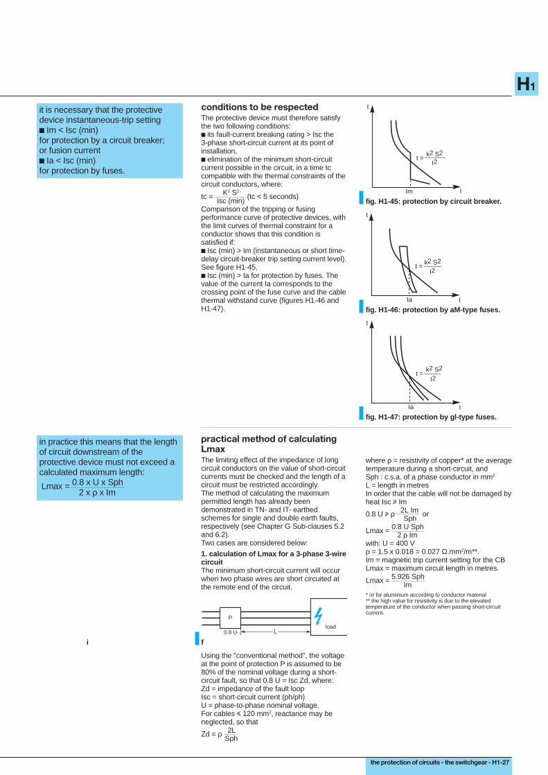
conditions to be respectedThe protective device must therefore satisfythe two following conditions:c its fault-current breaking rating > Isc the3-phase short-circuit current at its point ofinstallation,c elimination of the minimum short-circuitcurrent possible in the circuit, in a time tccompatible with the thermal constraints of thecircuit conductors, where:
tc = K2 S2 (tc < 5 seconds) Isc (min)Comparison of the tripping or fusingperformance curve of protective devices, withthe limit curves of thermal constraint for aconductor shows that this condition issatisfied if:c Isc (min) > Im (instantaneous or short time-delay circuit-breaker trip setting current level).See figure H1-45.c Isc (min) > Ia for protection by fuses. Thevalue of the current Ia corresponds to thecrossing point of the fuse curve and the cablethermal withstand curve (figures H1-46 andH1-47).
fig. H1-45: protection by circuit breaker.I
t
Im
t =k2 S2
I2
I
t
Ia
t =k2 S2
I2
fig. H1-46: protection by aM-type fuses.
I
t
Ia
t =k2 S2
I2
fig. H1-47: protection by gl-type fuses.
practical method of calculatingLmaxThe limiting effect of the impedance of longcircuit conductors on the value of short-circuitcurrents must be checked and the length of acircuit must be restricted accordingly.The method of calculating the maximumpermitted length has already beendemonstrated in TN- and IT- earthedschemes for single and double earth faults,respectively (see Chapter G Sub-clauses 5.2and 6.2).Two cases are considered below:
1. calculation of Lmax for a 3-phase 3-wirecircuitThe minimum short-circuit current will occurwhen two phase wires are short circuited atthe remote end of the circuit.
in practice this means that the lengthof circuit downstream of theprotective device must not exceed acalculated maximum length: Lmax = 0.8 x U x Sph
2 x ρ x Im
load
P
0.8 U L
fi
Using the "conventional method", the voltageat the point of protection P is assumed to be80% of the nominal voltage during a short-circuit fault, so that 0.8 U = Isc Zd, where:Zd = impedance of the fault loopIsc = short-circuit current (ph/ph)U = phase-to-phase nominal voltage.For cables i 120 mm2, reactance may beneglected, so that
Zd = ρ 2L Sph
where ρ = resistivity of copper* at the averagetemperature during a short-circuit, andSph : c.s.a. of a phase conductor in mm2
L = length in metresIn order that the cable will not be damaged byheat Isc u Im
0.8 U u ρ 2L Im or Sph
Lmax = 0.8 U Sph 2 ρ Imwith: U = 400 Vρ = 1.5 x 0.018 = 0.027 Ω.mm2/m**.Im = magnetic trip current setting for the CBLmax = maximum circuit length in metres.
Lmax = 5.926 Sph Im
* or for aluminium according to conductor material** the high value for resistivity is due to the elevatedtemperature of the conductor when passing short-circuitcurrent.
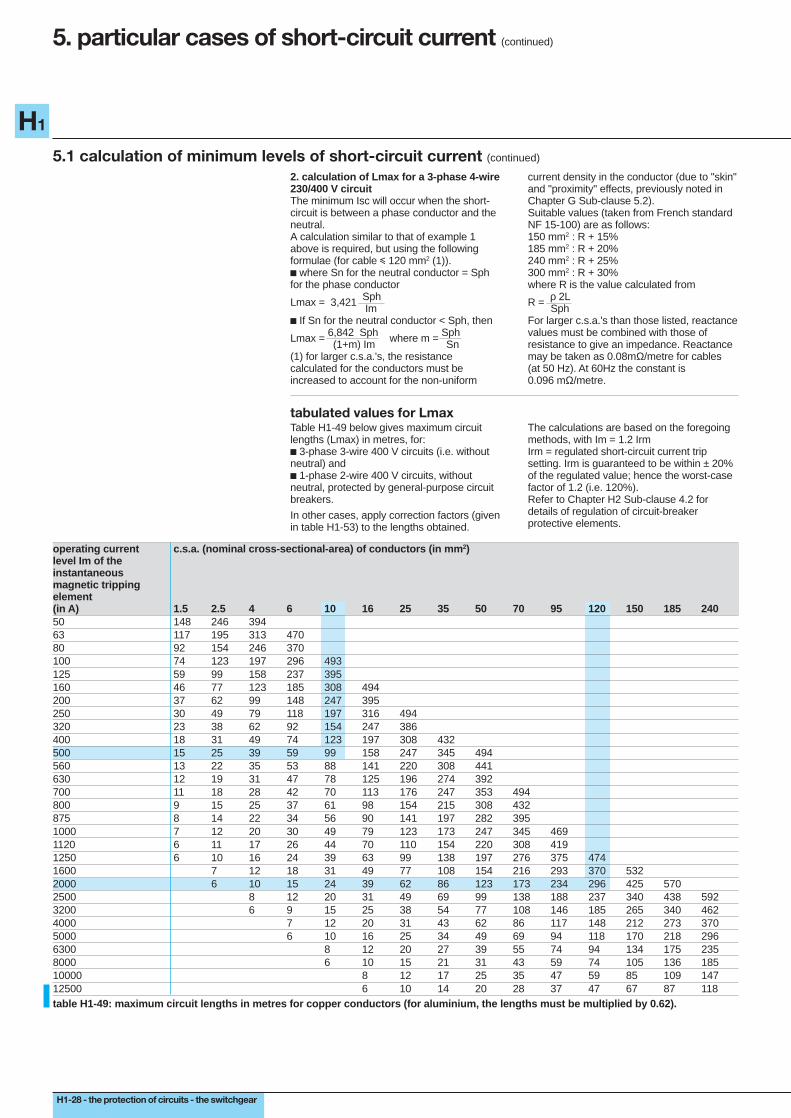
H1-28 - the protection of circuits - the switchgear
H1
5. particular cases of short-circuit current (continued)
5.1 calculation of minimum levels of short-circuit current (continued)
2. calculation of Lmax for a 3-phase 4-wire230/400 V circuitThe minimum Isc will occur when the short-circuit is between a phase conductor and theneutral.A calculation similar to that of example 1above is required, but using the followingformulae (for cable i 120 mm2 (1)).c where Sn for the neutral conductor = Sphfor the phase conductor
Lmax = 3,421 Sph Im
c If Sn for the neutral conductor < Sph, then
Lmax = 6,842 Sph where m = Sph (1+m) Im Sn(1) for larger c.s.a.'s, the resistancecalculated for the conductors must beincreased to account for the non-uniform
current density in the conductor (due to "skin"and "proximity" effects, previously noted inChapter G Sub-clause 5.2).Suitable values (taken from French standardNF 15-100) are as follows:150 mm2 : R + 15%185 mm2 : R + 20%240 mm2 : R + 25%300 mm2 : R + 30%where R is the value calculated from
R = ρ 2L SphFor larger c.s.a.'s than those listed, reactancevalues must be combined with those ofresistance to give an impedance. Reactancemay be taken as 0.08mΩ/metre for cables(at 50 Hz). At 60Hz the constant is0.096 mΩ/metre.
tabulated values for LmaxTable H1-49 below gives maximum circuitlengths (Lmax) in metres, for:c 3-phase 3-wire 400 V circuits (i.e. withoutneutral) andc 1-phase 2-wire 400 V circuits, withoutneutral, protected by general-purpose circuitbreakers.
In other cases, apply correction factors (givenin table H1-53) to the lengths obtained.
The calculations are based on the foregoingmethods, with Im = 1.2 IrmIrm = regulated short-circuit current tripsetting. Irm is guaranteed to be within ± 20%of the regulated value; hence the worst-casefactor of 1.2 (i.e. 120%).Refer to Chapter H2 Sub-clause 4.2 fordetails of regulation of circuit-breakerprotective elements.
operating current c.s.a. (nominal cross-sectional-area) of conductors (in mm 2)level Im of theinstantaneousmagnetic trippingelement(in A) 1.5 2.5 4 6 10 16 25 35 50 70 95 120 150 185 24050 148 246 39463 117 195 313 47080 92 154 246 370100 74 123 197 296 493125 59 99 158 237 395160 46 77 123 185 308 494200 37 62 99 148 247 395250 30 49 79 118 197 316 494320 23 38 62 92 154 247 386400 18 31 49 74 123 197 308 432500 15 25 39 59 99 158 247 345 494560 13 22 35 53 88 141 220 308 441630 12 19 31 47 78 125 196 274 392700 11 18 28 42 70 113 176 247 353 494800 9 15 25 37 61 98 154 215 308 432875 8 14 22 34 56 90 141 197 282 3951000 7 12 20 30 49 79 123 173 247 345 4691120 6 11 17 26 44 70 110 154 220 308 4191250 6 10 16 24 39 63 99 138 197 276 375 4741600 7 12 18 31 49 77 108 154 216 293 370 5322000 6 10 15 24 39 62 86 123 173 234 296 425 5702500 8 12 20 31 49 69 99 138 188 237 340 438 5923200 6 9 15 25 38 54 77 108 146 185 265 340 4624000 7 12 20 31 43 62 86 117 148 212 273 3705000 6 10 16 25 34 49 69 94 118 170 218 2966300 8 12 20 27 39 55 74 94 134 175 2358000 6 10 15 21 31 43 59 74 105 136 18510000 8 12 17 25 35 47 59 85 109 14712500 6 10 14 20 28 37 47 67 87 118table H1-49: maximum circuit lengths in metres for copper conductors (for aluminium, the lengths must be multiplied by 0.62).
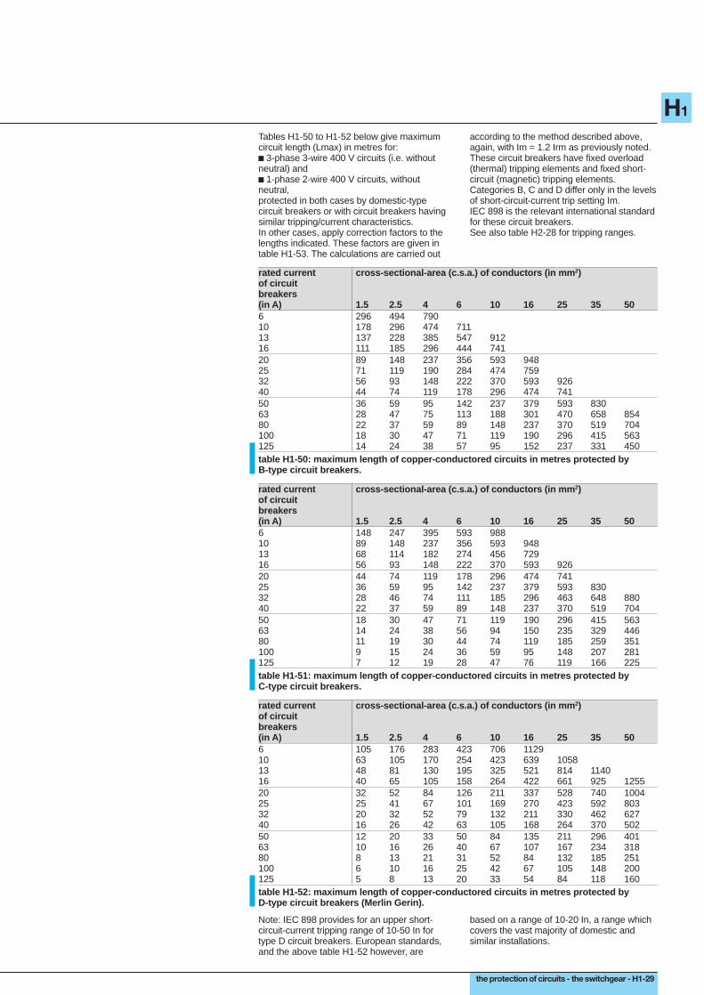
the protection of circuits - the switchgear - H1-29
H1
Tables H1-50 to H1-52 below give maximumcircuit length (Lmax) in metres for:c 3-phase 3-wire 400 V circuits (i.e. withoutneutral) andc 1-phase 2-wire 400 V circuits, withoutneutral,protected in both cases by domestic-typecircuit breakers or with circuit breakers havingsimilar tripping/current characteristics.In other cases, apply correction factors to thelengths indicated. These factors are given intable H1-53. The calculations are carried out
according to the method described above,again, with Im = 1.2 Irm as previously noted.These circuit breakers have fixed overload(thermal) tripping elements and fixed short-circuit (magnetic) tripping elements.Categories B, C and D differ only in the levelsof short-circuit-current trip setting Im.IEC 898 is the relevant international standardfor these circuit breakers.See also table H2-28 for tripping ranges.
rated current cross-sectional-area (c.s.a.) of conductors (in mm 2)of circuitbreakers(in A) 1.5 2.5 4 6 10 16 25 35 506 296 494 79010 178 296 474 71113 137 228 385 547 91216 111 185 296 444 74120 89 148 237 356 593 94825 71 119 190 284 474 75932 56 93 148 222 370 593 92640 44 74 119 178 296 474 74150 36 59 95 142 237 379 593 83063 28 47 75 113 188 301 470 658 85480 22 37 59 89 148 237 370 519 704100 18 30 47 71 119 190 296 415 563125 14 24 38 57 95 152 237 331 450table H1-50: maximum length of copper-conductored circuits in metres protected byB-type circuit breakers.
rated current cross-sectional-area (c.s.a.) of conductors (in mm 2)of circuitbreakers(in A) 1.5 2.5 4 6 10 16 25 35 506 148 247 395 593 98810 89 148 237 356 593 94813 68 114 182 274 456 72916 56 93 148 222 370 593 92620 44 74 119 178 296 474 74125 36 59 95 142 237 379 593 83032 28 46 74 111 185 296 463 648 88040 22 37 59 89 148 237 370 519 70450 18 30 47 71 119 190 296 415 56363 14 24 38 56 94 150 235 329 44680 11 19 30 44 74 119 185 259 351100 9 15 24 36 59 95 148 207 281125 7 12 19 28 47 76 119 166 225table H1-51: maximum length of copper-conductored circuits in metres protected byC-type circuit breakers.
rated current cross-sectional-area (c.s.a.) of conductors (in mm 2)of circuitbreakers(in A) 1.5 2.5 4 6 10 16 25 35 506 105 176 283 423 706 112910 63 105 170 254 423 639 105813 48 81 130 195 325 521 814 114016 40 65 105 158 264 422 661 925 125520 32 52 84 126 211 337 528 740 100425 25 41 67 101 169 270 423 592 80332 20 32 52 79 132 211 330 462 62740 16 26 42 63 105 168 264 370 50250 12 20 33 50 84 135 211 296 40163 10 16 26 40 67 107 167 234 31880 8 13 21 31 52 84 132 185 251100 6 10 16 25 42 67 105 148 200125 5 8 13 20 33 54 84 118 160table H1-52: maximum length of copper-conductored circuits in metres protected byD-type circuit breakers (Merlin Gerin).
Note: IEC 898 provides for an upper short-circuit-current tripping range of 10-50 In fortype D circuit breakers. European standards,and the above table H1-52 however, are
based on a range of 10-20 In, a range whichcovers the vast majority of domestic andsimilar installations.
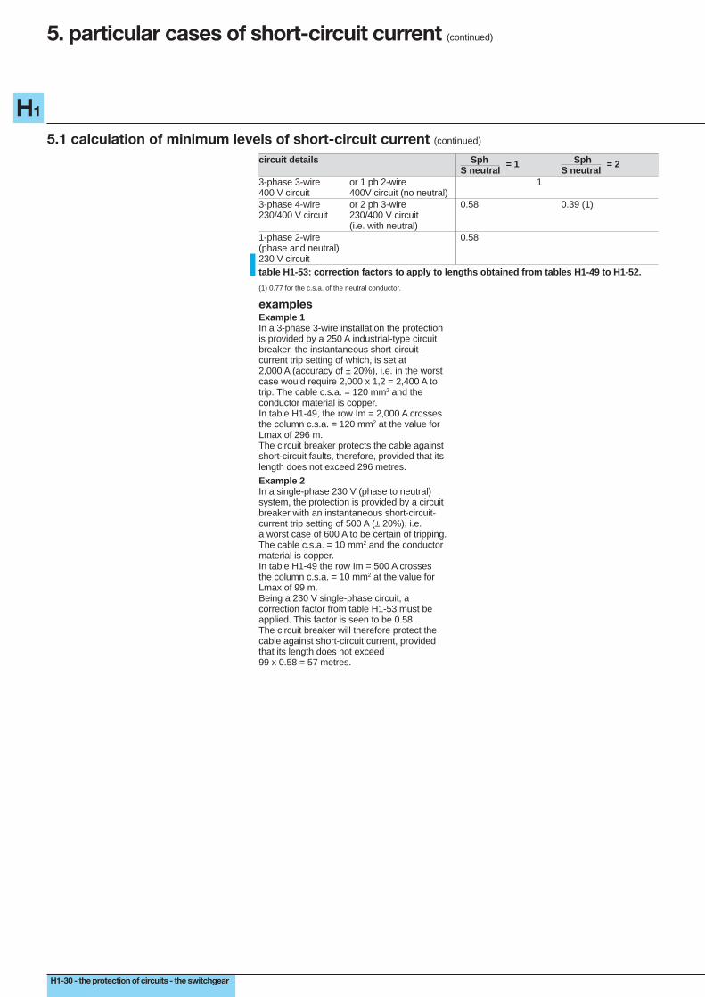
H1-30 - the protection of circuits - the switchgear
H1
5. particular cases of short-circuit current (continued)
5.1 calculation of minimum levels of short-circuit current (continued)
circuit details Sph = 1 Sph = 2S neutral S neutral
3-phase 3-wire or 1 ph 2-wire 1400 V circuit 400V circuit (no neutral)3-phase 4-wire or 2 ph 3-wire 0.58 0.39 (1)230/400 V circuit 230/400 V circuit
(i.e. with neutral)1-phase 2-wire 0.58(phase and neutral)230 V circuittable H1-53: correction factors to apply to lengths obtained from tables H1-49 to H1-52.
(1) 0.77 for the c.s.a. of the neutral conductor.
examplesExample 1In a 3-phase 3-wire installation the protectionis provided by a 250 A industrial-type circuitbreaker, the instantaneous short-circuit-current trip setting of which, is set at2,000 A (accuracy of ± 20%), i.e. in the worstcase would require 2,000 x 1,2 = 2,400 A totrip. The cable c.s.a. = 120 mm2 and theconductor material is copper.In table H1-49, the row Im = 2,000 A crossesthe column c.s.a. = 120 mm2 at the value forLmax of 296 m.The circuit breaker protects the cable againstshort-circuit faults, therefore, provided that itslength does not exceed 296 metres.
Example 2In a single-phase 230 V (phase to neutral)system, the protection is provided by a circuitbreaker with an instantaneous short-circuit-current trip setting of 500 A (± 20%), i.e.a worst case of 600 A to be certain of tripping.The cable c.s.a. = 10 mm2 and the conductormaterial is copper.In table H1-49 the row Im = 500 A crossesthe column c.s.a. = 10 mm2 at the value forLmax of 99 m.Being a 230 V single-phase circuit, acorrection factor from table H1-53 must beapplied. This factor is seen to be 0.58.The circuit breaker will therefore protect thecable against short-circuit current, providedthat its length does not exceed99 x 0.58 = 57 metres.

the protection of circuits - the switchgear - H1-31
H1
5.2 verification of the withstand capabilities of cables under short-circuit conditions
in general verification of thethermal-withstand capability of acable is not necessary, except incases where cables of small c.s.a.are installed close to, or feedingdirectly from, the main generaldistribution board.
thermal constraintsWhen the duration of short-circuit current isbrief (several tenths of a second up to fiveseconds maximum) all of the heat producedis assumed to remain in the conductor,causing its temperature to rise. The heatingprocess is said to be adiabatic, anassumption that simplifies the calculation andgives a pessimistic result, i.e. a higherconductor temperature than that which wouldactually occur, since in practice, some heatwould leave the conductor and pass into theinsulation.For a period of 5 seconds or less, therelationship I2t = k2 S2 characterizes the timein seconds during which a conductor of c.s.a.S (in mm2) can be allowed to carry a currentI amps, before its temperature reaches alevel which would damage the surroundinginsulation.
The factor k2 is given in table H1-54 below,and is abstracted from the French standardsNF C 15-100.The method of verification consists inchecking that the thermal energy I2t per ohmof conductor material, allowed to pass by theprotecting circuit-breaker (from manufacturerscatalogues) is less than that permitted for theparticular conductor (as given in table H1-55below).
insulation conductor conductorcopper (Cu) aluminium (Al)
PVC 13225 5776PR 20449 8836table H1-54: value of the constant k 2.
S (mm2) PVC XLPEcopper aluminium copper aluminium
k 115 76 143 94k2 13225 5776 20449 88361.5 0.0297 0.0130 0.0460 0.01992.5 0.0826 0.0361 0.1278 0.05524 0.2116 0.0924 0.3272 0.14146 0.4761 0.2079 0.7362 0.318110 1.3225 0.5776 2.0450 0.883616 3.3856 1.4786 5.2350 2.262025 8.2656 3.6100 12.7806 5.522535 16.2006 7.0756 25.0500 10.824150 29.839 13.032 46.133 19.936table H1-55: maximum allowable thermal stress for cables(expressed in amperes 2 x seconds x 10 6).
Example:Is a copper-cored XLPE cable of 4 mm2 c.s.a.adequately protected by a C60N circuitbreaker (Merlin Gerin)?The above table shows that the I2t value forthe cable is 0.3272 x 10⁶, while the maximum"let-through" value by the circuit breaker, asgiven in the manufacturer's catalogue, isconsiderably less, and amounts to0.094 x 106 ampere2-seconds.The cable is therefore adequately protectedby the circuit breaker up to its full ratedbreaking capability.
electrodynamic constraintsFor bus-trunking and other kinds ofprefabricated pre-conductored channels,rails, etc. it is necessary to verify that theelectrodynamic withstand performance whencarrying short-circuit currents is satisfactory.The peak value of current, limited by thecircuit breaker or fuse, must be less than thatfor which the pre-conductored system israted.Tables of coordination ensuring adequateprotection of their products are generallypublished by the manufacturers of suchsystems.

H1-32 - the protection of circuits - the switchgear
H1
6. protective earthing conductors (PE)
6.1 connection and choice
connection, choice and dimensioningof PE conductors (extracted fromIEC standards and the Frenchstandard NF C 15-100)
Protective (PE) conductors provide thebonding connection between all exposed andextraneous conductive parts of an installation,to create the main equipotential bondingsystem. These conductors conduct faultcurrent due to insulation failure (between aphase conductor and an exposed conductivepart) to the earthed neutral of the source. P.E.conductors are connected to the mainearthing terminal of the installation.The main earthing terminal is connected tothe earthing electrode (see Chapter F) by theearthing conductor (grounding electrodeconductor in USA).PE conductors must be:c insulated and coloured yellow and green(stripes);c be protected against mechanical andchemical damage.In IT and TN-earthed schemes it is stronglyrecommended that PE conductors should beinstalled in close proximity (i.e. in the sameconduits, on the same cable tray, etc.) as thelive cables of the related circuit. Thisarrangement ensures the minimum possibleinductive reactance in the earth-fault current-carrying circuits.
connectionPE conductors must:c not include any means of breaking thecontinuity of the circuit (such as a switch,removable links, etc.);c connect exposed conductive partsindividually to the main PE conductor, i.e.in parallel, not in series, as shown in figureH1-56;c have an individual terminal on commonearthing bars in distribution boards.
TT schemeThe PE conductor need not necessarily beinstalled in close proximity to the liveconductors of the corresponding circuit, sincehigh values of earth-fault current are notneeded to operate the RCD-type of protectionused in TT installations.
IT and TN schemesThe PE or PEN conductor, as previouslynoted, must be installed as close by aspossible to the corresponding live conductorsof the circuit and no ferro-magnetic materialmust be interposed between them. A PENconductor must always be connected directlyto the earth terminal of an appliance, with alooped connection from the earth terminal tothe neutral terminal of the appliance(figure H1-57).c TN-C scheme (the neutral and PEconductor are one and the same, referred toas a PEN conductor). The protective functionof a PEN conductor has priority, so that allrules governing PE conductors apply strictlyto PEN conductors;c TN-C to TN-S transitionThe PE conductor for the installlation isconnected to the PEN terminal or bar(figure H1-58) generally at the origin of theinstallation. Downstream of the point ofseparation, no PE conductor can beconnected to the neutral conductor.
PE
PE
correct
incorrect
fig. H1-56: a poor connection in a seriesarrangement will leave all downstreamappliances unprotected.
PEN
fig. H1-57: direct connection of the PENconductor to the earth terminal of anappliance.
PEN PE
N
fig. H1-58: the TN-C-S scheme.
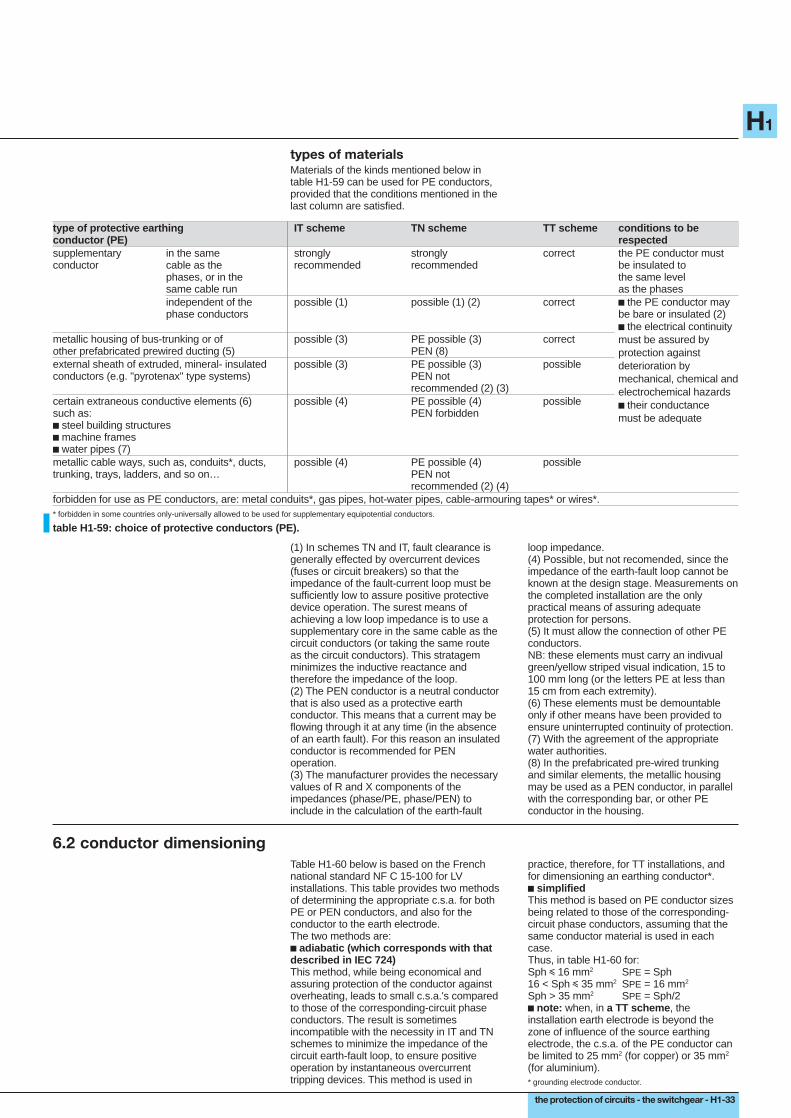
the protection of circuits - the switchgear - H1-33
H1
types of materialsMaterials of the kinds mentioned below intable H1-59 can be used for PE conductors,provided that the conditions mentioned in thelast column are satisfied.
type of protective earthing IT scheme TN scheme TT scheme conditions to beconductor (PE) respectedsupplementary in the same strongly strongly correct the PE conductor mustconductor cable as the recommended recommended be insulated to
phases, or in the the same levelsame cable run as the phasesindependent of the possible (1) possible (1) (2) correct c the PE conductor mayphase conductors be bare or insulated (2)
metallic housing of bus-trunking or of possible (3) PE possible (3) correctother prefabricated prewired ducting (5) PEN (8)external sheath of extruded, mineral- insulated possible (3) PE possible (3) possibleconductors (e.g. "pyrotenax" type systems) PEN not
recommended (2) (3)certain extraneous conductive elements (6) possible (4) PE possible (4) possiblesuch as: PEN forbiddenc steel building structuresc machine framesc water pipes (7)metallic cable ways, such as, conduits*, ducts, possible (4) PE possible (4) possibletrunking, trays, ladders, and so on… PEN not
recommended (2) (4)forbidden for use as PE conductors, are: metal conduits*, gas pipes, hot-water pipes, cable-armouring tapes* or wires*.
c the electrical continuitymust be assured byprotection againstdeterioration bymechanical, chemical andelectrochemical hazardsc their conductancemust be adequate
* forbidden in some countries only-universally allowed to be used for supplementary equipotential conductors.
table H1-59: choice of protective conductors (PE).
(1) In schemes TN and IT, fault clearance isgenerally effected by overcurrent devices(fuses or circuit breakers) so that theimpedance of the fault-current loop must besufficiently low to assure positive protectivedevice operation. The surest means ofachieving a low loop impedance is to use asupplementary core in the same cable as thecircuit conductors (or taking the same routeas the circuit conductors). This stratagemminimizes the inductive reactance andtherefore the impedance of the loop.(2) The PEN conductor is a neutral conductorthat is also used as a protective earthconductor. This means that a current may beflowing through it at any time (in the absenceof an earth fault). For this reason an insulatedconductor is recommended for PENoperation.(3) The manufacturer provides the necessaryvalues of R and X components of theimpedances (phase/PE, phase/PEN) toinclude in the calculation of the earth-fault
loop impedance.(4) Possible, but not recomended, since theimpedance of the earth-fault loop cannot beknown at the design stage. Measurements onthe completed installation are the onlypractical means of assuring adequateprotection for persons.(5) It must allow the connection of other PEconductors.NB: these elements must carry an indivualgreen/yellow striped visual indication, 15 to100 mm long (or the letters PE at less than15 cm from each extremity).(6) These elements must be demountableonly if other means have been provided toensure uninterrupted continuity of protection.(7) With the agreement of the appropriatewater authorities.(8) In the prefabricated pre-wired trunkingand similar elements, the metallic housingmay be used as a PEN conductor, in parallelwith the corresponding bar, or other PEconductor in the housing.
6.2 conductor dimensioningTable H1-60 below is based on the Frenchnational standard NF C 15-100 for LVinstallations. This table provides two methodsof determining the appropriate c.s.a. for bothPE or PEN conductors, and also for theconductor to the earth electrode.The two methods are:c adiabatic (which corresponds with thatdescribed in IEC 724)This method, while being economical andassuring protection of the conductor againstoverheating, leads to small c.s.a.'s comparedto those of the corresponding-circuit phaseconductors. The result is sometimesincompatible with the necessity in IT and TNschemes to minimize the impedance of thecircuit earth-fault loop, to ensure positiveoperation by instantaneous overcurrenttripping devices. This method is used in
practice, therefore, for TT installations, andfor dimensioning an earthing conductor*.c simplifiedThis method is based on PE conductor sizesbeing related to those of the corresponding-circuit phase conductors, assuming that thesame conductor material is used in eachcase.Thus, in table H1-60 for:Sph i 16 mm2 SPE = Sph16 < Sph i 35 mm2 SPE = 16 mm2
Sph > 35 mm2 SPE = Sph/2c note: when, in a TT scheme , theinstallation earth electrode is beyond thezone of influence of the source earthingelectrode, the c.s.a. of the PE conductor canbe limited to 25 mm2 (for copper) or 35 mm2
(for aluminium).* grounding electrode conductor.
H1-34 - the protection of circuits - the switchgear
H1
k values nature of insulationpolyvinylchloride (PVC) cross-linked-polyethylene
(XLPE)ethylene-propylene-rubber(EPR)
final 160 250temperature ( °C)insulated conductors initial temperature initial temperaturenot incoporated in cables θ initial = 30 °C θ initial = 30 °Cor bare conductorsin contact withcable jackets
copper 143 176aluminium 95 116steel 52 64
conductors of a initial temperature initial temperaturemulti-core-cable θ initial = 30 °C θ initial = 30 °C
copper 115 143aluminium 76 94
6. protective earthing conductors (PE) (continued)
The neutral cannot be used as a PENconductor unless its c.s.a. is equal to orlarger than 10 mm2 (copper) or 16 mm2
(aluminium).Moreover, a PEN conductor is not allowed ina flexible cable. Since a PEN conductorfunctions also as a neutral conductor, itsc.s.a. cannot, in any case, be less than thatnecessary for the neutral, as discuss in Sub-clause 7.1 of this Chapter.This c.s.a. cannot be less than that of thephase conductors unless:
6.2 conductor dimensioning (continued)
c the kVA rating of single-phase loads is lessthan 10% of the total kVA load, andc Imax likely to pass through the neutral innormal circumstances, is less than thecurrent permitted for the cable size selected.Furthermore, protection of the neutralconductor must be assured by the protectivedevices provided for phase-conductorprotection (described in Sub-clause 7.2of this Chapter).
c.s.a. of phase c.s.a. of c.s.a. of c.s.a. of earthing conductor betweenconductors Sph (mm 2) PE conductor PEN conductor the installation earth electrode
Cu Alu and the main earth terminalsimplified i 16 i 16 SPE = Sph (1) c when protected against mechanicalmethod 25
SPE = 16damage: S = I √t (2)
25,35 35 k> 35 > 35 SPE = Sph/2
adiabatic any size SPE = I √t (1) (2)method k
SPEN = Sph with minimum10/mm2 Cu, 16/mm2 AluSPEN = Sph/2 à Sph (3) withminimum 16/mm2 Cu, 25/mm2 Alu c without mechanical protection, but
protected against corrosion byimpermeable cable sheath. Minimum16 mm2 for copper or galvanized steel.c without either of the above protections;minimum of 25 mm2 for bare copper and50 mm2 for bare galvanized steel.
table H1-60: minimum c.s.a.'s for PE conductors and earthing conductors (to the installation earth electrode).
(1) When the PE conductor is separated from the circuit phase conductors, the followingminimum values must be respected:c 2.5 mm2 if the PE is mechanically protectedc 4 mm2 if the PE is not mechanically protected.(2) Refer to table H1-55 for the application of this formula.(3) According to the conditions prescribed in the introduction to this table.
values of factor k to be used inthe formulae (2)These values are identical in several nationalstandards, and the temperature rise ranges,together with factor k values and the uppertemperature limits for the different classesof insulation, correspond with those publishedin IEC 724 (1984).
The data presented in table H1-61 are thosemost commonly needed for LV installationdesign.
table H1-61: k factor values for LV PE conductors, commonly used in national standardsand complying with IEC 724.
the protection of circuits - the switchgear - H1-35
H1
6.3 protective conductor between the HV/LV transformer and the main general distributionboard (MGDB)
All phase and neutral conductors upstream ofthe main incoming circuit breaker controllingand protecting the MGDB are protected bydevices at the HV side of the transformer.The conductors in question, together with thePE conductor, must be dimensionedaccordingly. Dimensioning of the phase andneutral conductors from the transformer isexemplified in Sub-clause 1.6 of this chapter(for circuit C1 of the system illustrated infig. H1-8).Recommended conductor sizes for bare andinsulated PE conductors from the transformerneutral point, shown in figure H1-62, areindicated below in table H1-63. The kVArating to consider is the sum of all (if morethan one) transformers connected to theMGDB.The table indicates the c.s.a. of theconductors in mm2 according to:c the nominal rating of the HV/LVtransformer(s) in kVA;c the fault-current clearance time by the HVprotective devices, in seconds,
PEMGDB
main earth barfor the LV installation
fig. H1-62: PE conductor to the main earthbar in the MGDB.
c the kinds of insulation and conductormaterials.If the HV protection is by fuses, then use the0.2 seconds columns.In IT schemes, if an overvoltage protectiondevice is installed (between the transformerneutral point and earth) the conductors forconnection of the device should also bedimensioned in the same way as thatdescribed above for PE conductors.
P conductor conductors conductors conductors(kVA) material bare PVC-insulated XLPE-insulatedLV voltages copper t(s) 0.2 s 0.5 s - 0.2 s 0.5 s - 0.2 s 0.5 s -127/ 230/ aluminium t(s) - 0.2 s 0.5 s - 0.2 s 0.5 s - 0.2 s 0.5 s220 V 400 Vi 63 i 100 c.s.a. of PE 25 25 25 25 25 25 25 25 25100 160 conductors 25 25 35 25 25 50 25 25 35125 200 SPE (mm2) 25 35 50 25 35 50 25 25 50160 250 25 35 70 35 50 70 25 35 50200 315 35 50 70 35 50 95 35 50 70250 400 50 70 95 50 70 95 35 50 95315 500 50 70 120 70 95 120 50 70 95400 630 70 95 150 70 95 150 70 95 120500 800 70 120 150 95 120 185 70 95 150630 1000 95 120 185 95 120 185 70 120 150800 1250 95 150 185 120 150 240 95 120 185
these conductors must bedimensioned according to nationalpractices.
table H1-63: c.s.a. of PE conductor between the HV/LV transformer and the MGDB, interms of transformer ratings and fault-clearance times used in France.
6.4 equipotential conductorThe main equipotential conductorThis conductor must, in general, have a c.s.a.at least equal to a half of that of the largestPE conductor, but in no case need exceed25 mm2 (copper) or 35 mm2 (aluminium)while its minimum c.s.a. is 6 mm2 (copper) or10 mm2 (aluminium).
Supplementary equipotential conductorThis conductor allows an exposed conductivepart which is remote from the nearest mainequipotential conductor (PE conductor) to beconnected to a local protective conductor. Itsc.s.a. must be at least a half of that of theprotective conductor to which it is connected.If it connects two exposed conductive parts(M1 and M2 in figure H1-64) its c.s.a. must beat least equal to that of the smaller of the twoPE conductors (for M1 and M2). Equipotentialconductors which are not incorporated in acable, should be protected mechanically byconduits, ducting, etc. wherever possible.Other important uses for supplementaryequipotential conductors concern thereduction of the earth-fault-loop impedance,particulary for indirect-contact protectionschemes in TN- or IT-earthed installations,and in special locations with increasedelectrical risk (IEC 364-4-41 refers).
– between two exposed conductive parts,if SPE1 i SPE2if SLS = SPE1
– between an exposed conductive part and a metallic structure
(*) with a minimum of 2.5 mm2 for mechanically protected conductors ;4 mm2 for conductors not mechanically protected copper equivalent
M1 M2
SPE1 SPE2SLS
SLS =SPE
2SPE1
SLS
metal structures(conduits, girders, …)
M1
fig. H1-64: supplementary equipotentialconductors.

H1-36 - the protection of circuits - the switchgear
H1
7. the neutral conductor
The c.s.a. and the protection of the neutralconductor, apart from its current-carryingrequirement, depend on several factors,namely:c the type of earthing system, TT, TN, etc.;c method of protection against indirect-contact hazards according to the methodsdescribed below.
7.1 dimensioning the neutral conductorinfluence of the type of earthingsystemTT, TN-S and IT schemesc single-phase circuits or those of c.s.a.i 16 mm2 (copper) 25 mm2 (aluminium): thec.s.a. of the neutral conductor must be equalto that of the phases;c three-phase circuits of c.s.a. > 16 mm2
copper or 25 mm2 aluminium:the c.s.a. of the neutral may be chosen to be:v equal to that of the phase conductors, orv smaller, on condition that:- the current likely to flow through the neutralin normal conditions is less than the permittedvalue Iz. The influence of triplen* harmonicsmust be given particular consideration, aspreviously noted in Chapter F Sub-clause2.2, or:- the single-phase power of the circuit is lessthan 10% of the balanced 3-phase power ofthe circuit, or:- the neutral conductor is protected againstshort-circuit, in accordance with the followingSub-clause H1-7.2.* the 3rd and multiples of the 3rd harmonic.
TN-C schemeThe same conditions apply in theory as thosementioned above, but in practice, the neutralconductor must not be open-circuited underany circumstances since it constitutes a PEas well as a neutral conductor (see table H1-60 "c.s.a. of PEN conductor" column).
IT schemeIn general, it is not recommended to distributethe neutral conductor, i.e. a 3-phase 3-wirescheme is preferred.
When a 3-phase 4-wire installation isnecesssary, however, the conditionsdescribed above for TT and TN-S schemesare applicable.
7.2 protection of the neutral conductorTable H1-65 summarizes the several possiblecases. The table has been based on Frenchnational standards (NF C 15-100). Thefollowing points however, should beconsidered when referring to the table.
Circuit isolationIt is considered to be good practice that everycircuit be provided with the means for itsisolation.
Circuit breakingTable H1-65 is based on circuit breakers,which in the event of a fault, will open allpoles, including the neutral pole, i.e. thecircuit breakers are omnipolar. This table canalso be used for fuses able to emulate thisomnipolar opening.The action can only be achieved with fuses inan indirect way, in which the operation of oneor more fuses provokes a mechanical trip-outof all poles of an associated series-connectedload-break switch.The action is commonly caused by a striker-pin which is projected by means of anexplosive cartridge (triggered by the blowingfuse) against the switch tripping mechanism.Reclosing of the switch however, must bepossible only when the used cartridge hasbeen replaced by a new one.
Protection against electric shocksTable H1-65 takes into account the fact thatprotection against indirect-contact dangersdepend either on 300 mA RCDs (TT system)or on circuit breakers (TN and IT systems).
the protection of circuits - the switchgear - H1-37
H1
earthing systemsTT TN-C TN-S IT
reminder: protection by RCD provided by circuit according to the provided by circuit breakersagainst indirect breakers or fuses with method of protection or fuses and one RCD at leastcontact Ia (fuses) or Im (CB) chosen for each group of appliances
< Isc (min) connected to an earthelectrode (see figure G20)
protected circuit1-phase P-Nphase/neutral
1-phase 2Pphase/phase
3-phase 3P3-wire
3-phase 3P-N4-wire Sn = Sph*
3P-NSn < Sph
(A)
(B)
(A)
(B)
(C)
(C)
(C)
* Sn = c.s.a. of neutral conductorSph = c.s.a. of phase
table H1-65: table of protection schemes for neutral conductors in different earthing systems.
Symbol for overcurrent and short-circuittripping devices.(A) authorized for TT and TN schemes if aRCD is installed at the origin of the circuit orupstream of it, and if no artificial neutral isdistributed downstream of its location.(B) authorized for TT and TN schemes if theneutral conductor is protected against short-circuits by protective arrangements made forthe phases, and if the normal service currentis substantially less than the maximumpermissible for the neutral conductorconcerned.(C) authorized for IT schemes in certainconditions, viz: if the circuit breakercontrolling a number of homogeneous (i.e.similar) final circuits, of which the ratio of theextreme circuit ratings does not exceed 2,and which are protected against a secondfault occurring elsewhere in the installation bya RCD of sensitivity i 15% of that of thecalibration of the final circuit having thesmallest c.s.a.Refer to example 2 for CB 5.
thermal magnetic

H1-38 - the protection of circuits - the switchgear
H1
7. the neutral conductor
7.2 protection of the neutral conductor (continued)
examplesExample 1: (figure H1-66)3-phase 4-wire circuit with 3 x 95 mm2 copperphase conductors and 1 x 50 mm2 copperneutral conductor. The installation isTT-earthed with RCD protection upstream.Single-phase power of load: 70 kVA(connected phase-neutral). Three-phasepower of load: 140 kVA. The condition ofsingle-phase power being < 10% of the3-phase power delivered (Sub-clause 7.1 TTand TN-S schemes) is not satisfied in thiscase, since 70/140 = 50%. A reduced neutralc.s.a. may however, be used, provided that itis correctly protected. A suitable circuitbreaker for this purpose would be a 4-poleunit rated at 250 A with 3 trip units (1 for eachphase) set at 250 A and 1 trip unit (for theneutral) set at 125 A. The operation of anyone (or more) of these tripping units will tripall four poles of the circuit breaker.
N
4-pole CB3 - 250 A1 - 125 A trip units
50 mm2
3-phase power140 kVA
1-phase power70 kVA
3-phaseloads
3 x 95 mm2
1-phaseloads
fig. H1-66: example 1.
Example 2: (fig. H1-67)An installation is IT-earthed with a distributedneutral (i.e. a 3-phase 4-wire system in whichthe neutral is not earthed). This arrangementis not recommended, particularly for small ormedium-sized installations, but it doesprovide two levels of voltage, e.g. 230 V and400 V. The interposition of a LV/LVtransformer in a 3-phase 3-wire IT scheme(as shown in figure H1-8) is a preferredmethod of obtaining the two levels of voltage,and in such a case, the neutral conductormay be earthed.
Circuit breaker 1, 2 and 3As in example 1, the circuits protected bythese CBs have a neutral conductor of 50%of the c.s.a. of the phase conductors. Thecircuit breakers will therefore be 4-pole units,with tripping devices similar to thosementioned in example 1.
Circuit breaker 5This arrangement corresponds with thatdescribed in (C) of table H1-65 concerning acircuit breaker connected directly to, andcontrolling the busbars from which a numberof similar final circuits, (protected by 2-pole,1-phase and neutral CBs) are supplied.Overcurrent tripping is provided on all out-going CBs, but the 4-pole incoming CB (no 5)has only the (300 mA) RCD protection(mentioned in (C) of table H1-65) themagnetic core of which embraces all4 conductors.It may be noted that circuit breaker 12supplies a long lighting circuit, the neutral andphase conductors of which have the samec.s.a. A 4-pole circuit breaker having 3tripping devices is therefore suitable (1 deviceper phase).
400 kVAHV LV
PIMcompact NS250N4-pole3d 250 A1d 125 A
3 x 120 mm2+1 x 70 mm2
3 x 185 mm2+1 x 95 mm2
NS100N3-pole3d 100 A
3 x 35 mm2
4 x 6 mm2 4 x 50 mm2 4 x 6 mm2 contactorLC1 D63
thermaloverloadrelay
3 x 16 mm2
30 kW58 A
3 x 50 mm2
PE PE
PE
2 single-core cables 120 mm2 per phase - 1 x 120 mm2 (neutral)
PEPE44 5 7 8 9 1011
12
4 x 70 mm2
2 x
2.5
mm
2
2 x
1.5
mm
2
2 x
1.5
mm
2
4 x
2.5
mm
2
DPN
PEN
6
PE
DPN DPN DPN DPN
NS100N4-pole 32 A300 mA
C60N4-pole4d 32 Adiff. HS300 mA
NS160N4-pole4d 125 A
C60N4-pole4d 32 A
NS160N3-pole3d 125 A
NS80HMA NS160N4-pole + MT100/1603d 160 Adiff. BS10 A
compact NS400N4-pole3d 250 A1d 125 A
outdoorlighting
3d = 3 tripping units4d = 4 tripping unitsdiff. HS = high-sensitivity differential trippingdiff. BS = low-sensitivity differential tripping
fig. H1-67: example 2.
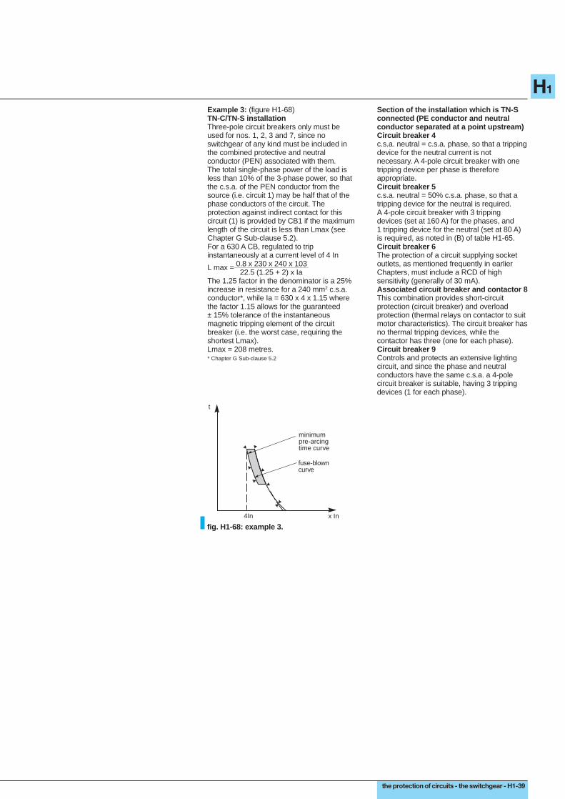
the protection of circuits - the switchgear - H1-39
H1
x In
t
4In
fuse-blowncurve
minimumpre-arcingtime curve
Example 3: (figure H1-68)TN-C/TN-S installationThree-pole circuit breakers only must beused for nos. 1, 2, 3 and 7, since noswitchgear of any kind must be included inthe combined protective and neutralconductor (PEN) associated with them.The total single-phase power of the load isless than 10% of the 3-phase power, so thatthe c.s.a. of the PEN conductor from thesource (i.e. circuit 1) may be half that of thephase conductors of the circuit. Theprotection against indirect contact for thiscircuit (1) is provided by CB1 if the maximumlength of the circuit is less than Lmax (seeChapter G Sub-clause 5.2).For a 630 A CB, regulated to tripinstantaneously at a current level of 4 In
L max = 0.8 x 230 x 240 x 103 22.5 (1.25 + 2) x IaThe 1.25 factor in the denominator is a 25%increase in resistance for a 240 mm2 c.s.a.conductor*, while Ia = 630 x 4 x 1.15 wherethe factor 1.15 allows for the guaranteed± 15% tolerance of the instantaneousmagnetic tripping element of the circuitbreaker (i.e. the worst case, requiring theshortest Lmax).Lmax = 208 metres.* Chapter G Sub-clause 5.2
Section of the installation which is TN-Sconnected (PE conductor and neutralconductor separated at a point upstream)Circuit breaker 4c.s.a. neutral = c.s.a. phase, so that a trippingdevice for the neutral current is notnecessary. A 4-pole circuit breaker with onetripping device per phase is thereforeappropriate.Circuit breaker 5c.s.a. neutral = 50% c.s.a. phase, so that atripping device for the neutral is required.A 4-pole circuit breaker with 3 trippingdevices (set at 160 A) for the phases, and1 tripping device for the neutral (set at 80 A)is required, as noted in (B) of table H1-65.Circuit breaker 6The protection of a circuit supplying socketoutlets, as mentioned frequently in earlierChapters, must include a RCD of highsensitivity (generally of 30 mA).Associated circuit breaker and contactor 8This combination provides short-circuitprotection (circuit breaker) and overloadprotection (thermal relays on contactor to suitmotor characteristics). The circuit breaker hasno thermal tripping devices, while thecontactor has three (one for each phase).Circuit breaker 9Controls and protects an extensive lightingcircuit, and since the phase and neutralconductors have the same c.s.a. a 4-polecircuit breaker is suitable, having 3 trippingdevices (1 for each phase).
fig. H1-68: example 3.