1. general information - coodie.com crf110f service repair manual...metric bolts, nuts and screws...
TRANSCRIPT
SERVICE RULES ··· ··········· ·· ·· ············ ······ ···· ··1-2
MODEL IDENTIFICATION ··· ···· ······ ······· ··· ·· ···1-2
SPECIFICATIONS ·· ··· ··············· ··· ··· ········· ······1-4
TORQUE VALUES ····················· ··· ··········· .... ·1-9
1. GENERAL INFORMATION
LUBRICATION & SEAL POINTS ·· ········· ···· 1-12
CABLE & HARNESS ROUTING···· ··· ·· ······ ·· 1·14
EMISSION CONTROL SYSTEMS ···· · ······ ···1-18
1-1
GENERAL INFORMATION
SERVICE RULES 1. Use genuine Honda or Honda-recommended parts and lubricants or their equivalents. Parts Ihat don't meet Honda's design
specifications may cause damage to the motorcycle. 2. Use the speciallools designed for this product to avoid damage and incorrect assembly. 3. Use only metric tools when servicing Ihe motorcycle. Metric bolts, nuts and screws are not interchangeable with English
fasteners. 4. Install new gaskets, O-rings, cotter pins, and lock plates when reassembling. 5. When tightening bolts or nuts, begin with the larger diameter or inner bolt first. Then tighten to the specified torque diagonally in
incremental steps unless a particular sequence is specified. 6. Clean parts in cleaning solvent upon disassembly. Lubricate any sliding surfaces before reassembly. 7. After reassembly, check all parts for proper installation and operation. 8. Route all electrical wires as shown in the Cable and Harness Routing (page 1-14).
ABBREVIATION Throughout this manual, the following abbreviations are used to identify the respective parts or systems.
Abbrev. term leM Ignition Control Module
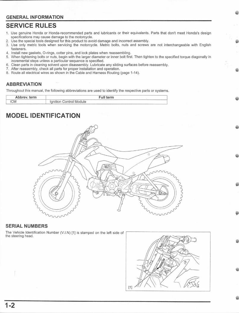
MODEL IDENTIFICATION
SERIAL NUMBERS
Full term
The Vehicle Identification Number (V.I.N) [1] is stamped on the left side of ,-------------------, the steering head.
11 I
1-2
•
•
•
II
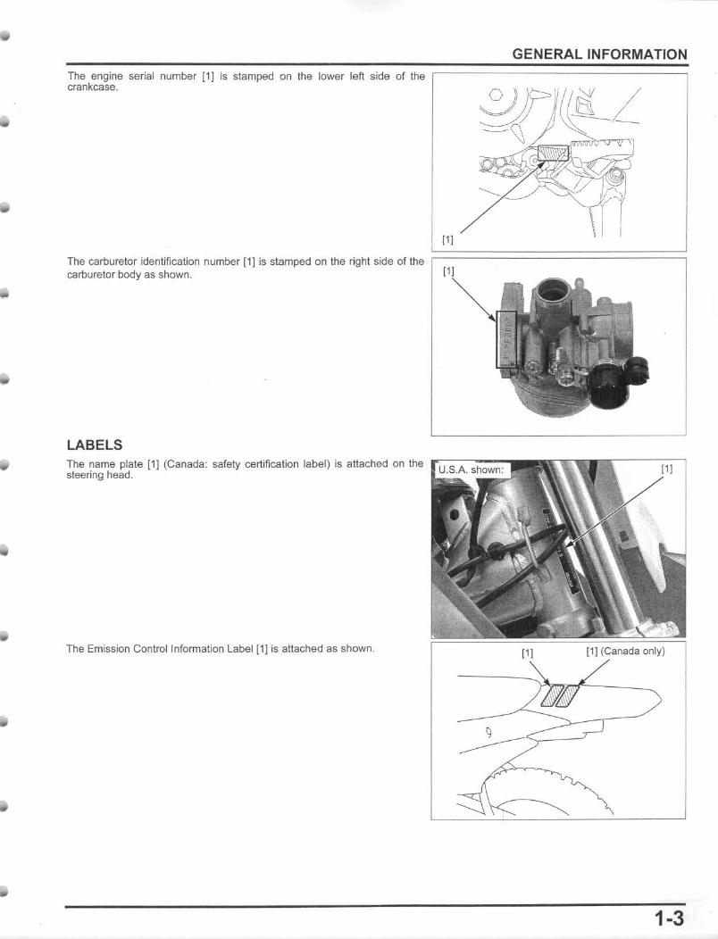
The engine serial number [1] is stamped on the lower left side of the crankcase.
111
GENERAL INFORMATION
The carl::luretor identification number [1] is stamped on Ihe right side of the ~=================~ carburetor body as shown.
LABELS The name plale [1) (Canada: safety certification label) is attached on the rc~-:--.,--sleering head .
The Emission Conlrollnformalion Label [1] is attached as shown. 11 J [1] (Canada only)
1-3
GENERAL INFORMATION
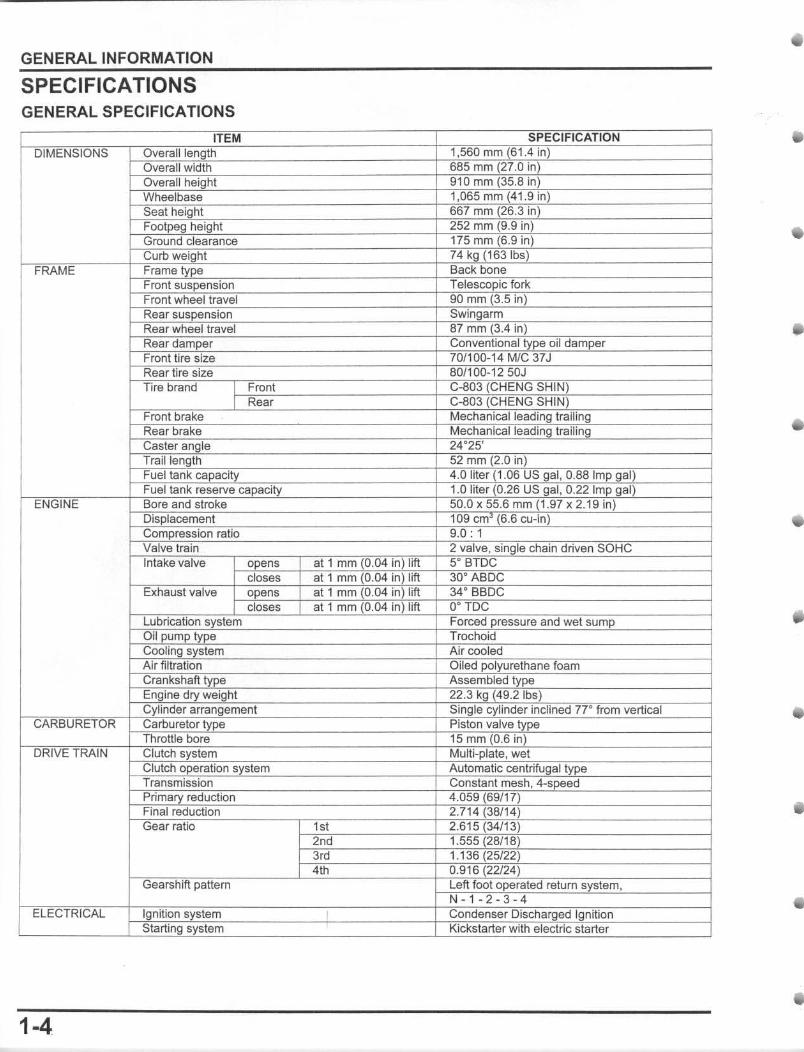
SPECIFICATIONS GENERAL SPECIFICATIONS
1-4
i I
•
•
•
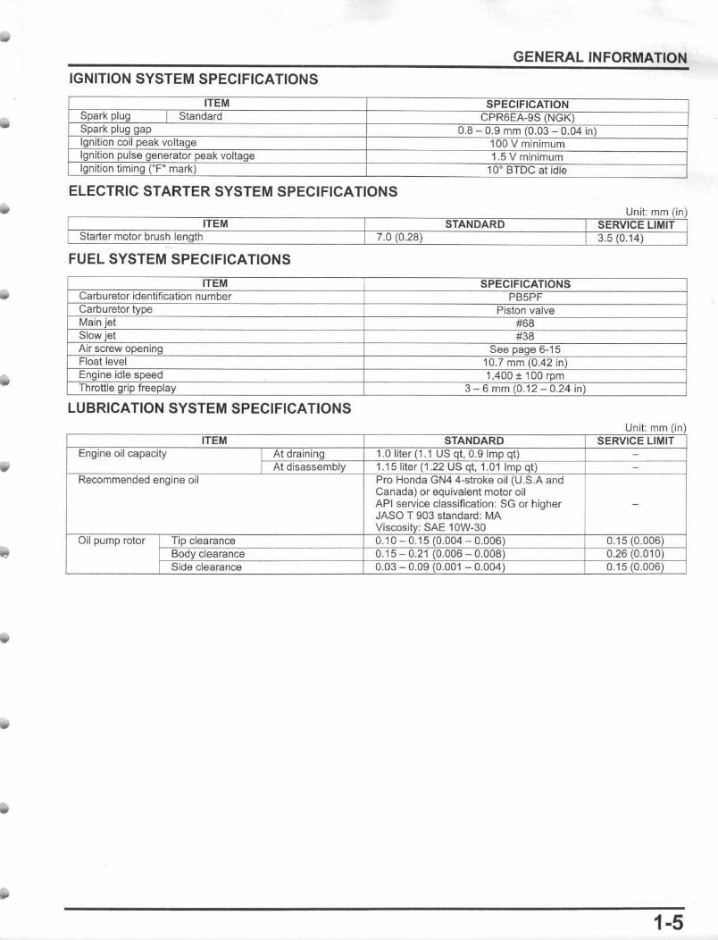
IGNITION SYSTEM SPECIFICATIONS
ITEM Sparl< plug Standard Spark plug gap Ignition coil peak voltage Ignition pulse generator peak voltage Ignition liming -F- mark)
GENERAL INFORMATION
SPECIFICATION CPR6EA-9S (NGK)
0.8 0.9 rnm (0.03 0.04 in) 100 V minimum 1.5 V minimum
10· BTDC al idle
ELECTRIC STARTER SYSTEM SPECIFICATIONS
FUEL SYSTEM SPECIFICATIONS
ITEM Carburetor identification number Carburetor type Main jet Slow jet Air screw opening Float level Engine idle speed Throttle grip free play
LUBRICATION SYSTEM SPECIFICATIONS
iI
SPECIFICATIONS PB5PF
Piston valve #68 #38
See page 6-15 10.7 mm 0.42 in) 1,400 ± 100 rpm
3 6mm(O.12 0.24 in)
Canada) or equivalent motor oil API service classification: SG or higher JASO T 903 standard : MA
: SAE 10W-3D
1-5
GENERAL INFORMATION
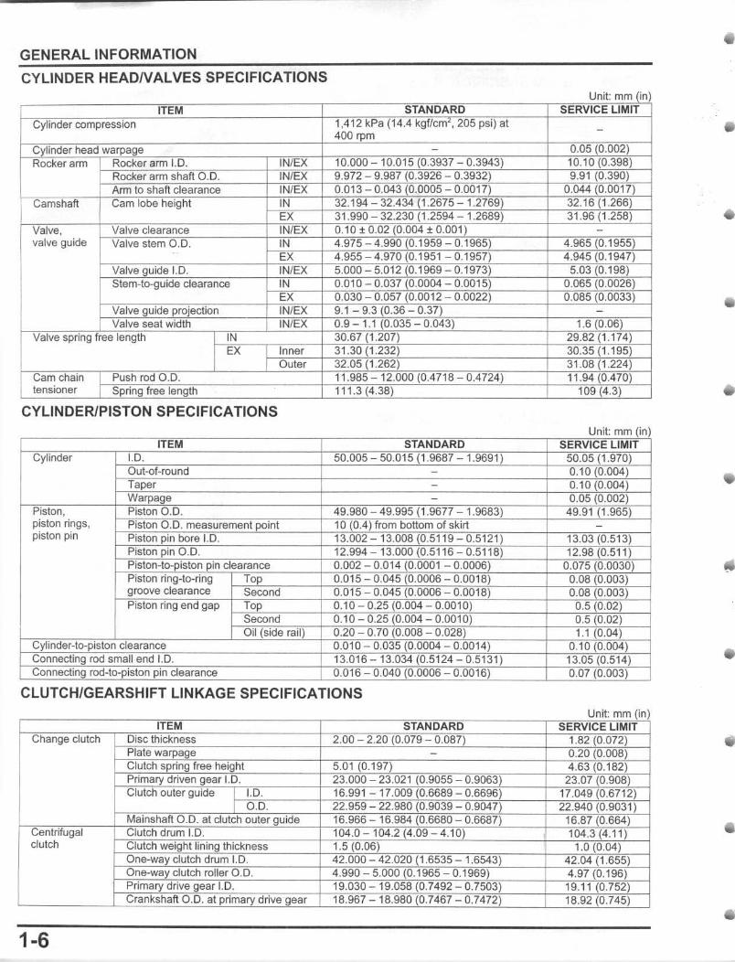
CYLINDER HEADNALVES SPECIFICATIONS
ann
valve guide
CYLINDER/PISTON SPECIFICATIONS
piston rings, piston pin
i I
CLUTCH/GEARSHIFT LINKAGE SPECIFICATIONS
clutch
1-6
Ii j
i I
•
•
•
•
•
•
•
GENERAL INFORMATION
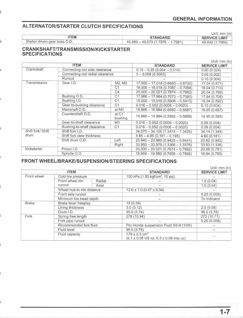
AL TERNATORISTARTER CLUTCH SPECIFICATIONS
ITEM STANDARD Starter driven gear boss 0.0. 45.660 45.673 1.7976 1.7981)
CRANKSHAFTITRANSMISSIONIKICKSTARTER SPECIFICATIONS
dcum
14.966 - 14.984 (0.5892 - 0.5899)
FRONT WHEEUBRAKEISUSPENSIONISTEERING SPECIFICATIONS
Unit: mm (in) SERVICE LIMIT 45.642 (1.7969)
14.95 (0.589)
Unit: mm I
1·7
GENERAL INFORMATION
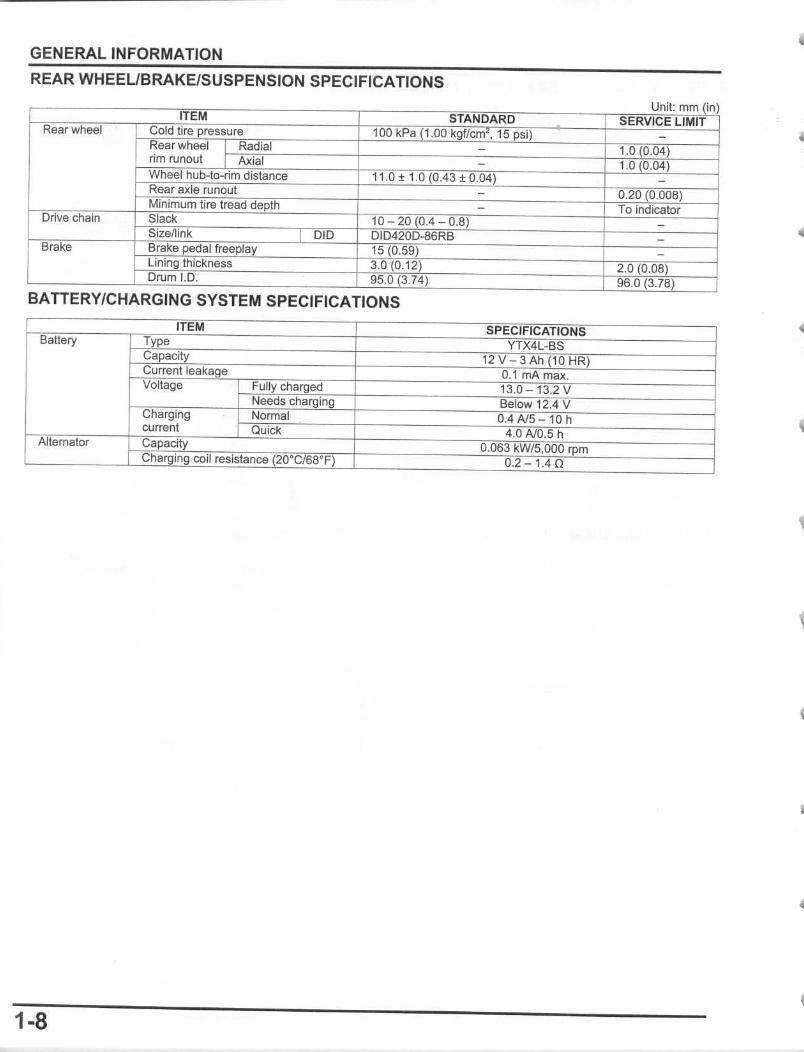
REAR WHEEUBRAKE/SUSPENSION SPECIFICATIONS
BATTERY/CHARGING SYSTEM SPECIFICATIONS
I
t
1-8
II
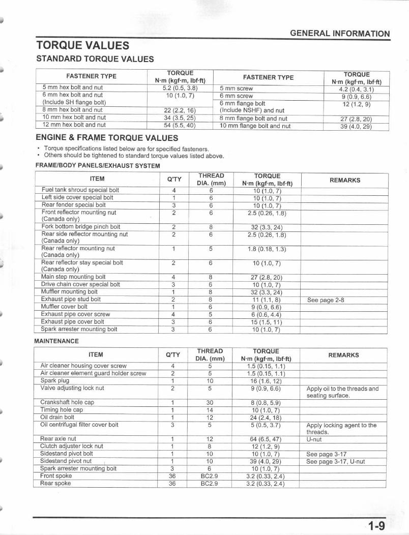
TORQUE VALUES STANDARD TORQUE VALUES
FASTENER TYPE
ENGINE & FRAME TORQUE VALUES • Torque specifications listed below are for specified fasteners. • Others should be lightened to standard torque values listed above.
FRAME/BODY PANELS/EXHAUST SYSTEM
ITEM Q'TY
MAINTENANCE
ITEM Q'TY
GENERAL INFORMATION
FASTENER TYPE N'm
REMARKS
REMARKS
1-9
GENERAL INFORMATION
IGNITION SYSTEM
C'TV THREAD TORQUE
REMARKS ITEM CIA. (mm) N'm (kgf·m . IbHl Timing hole ca 1 14 10 1.0,7)
ELECTRIC STARTER SYSTEM
ITEM C'TY THREAD TORQUE REMARKS CIA. mm) N'm (kgf·m. lbHt)
Starter motor cable screw 4 2 (0.2, 1.5
FUEL SYSTEM
ITEM C'TV THREAD TORQUE REMARKS
CIA. mm) N'm (kgf-m, IbUt Fuel tank mountin bott 3 8 21 2.1 , 16 Intake pipe mounting bolt 2 6 12(1,2, 9) Slow jet 1 1.5 (0.15, 1.1) Main jet 1 1.5 (0.15, 1.1) Needle ' t holder 1 2,5 (0,25, 1.8) Float chamber screw 2 4 2.1 0.21 , 1.5 Float chamber drain screw 1 1.5(0.15, 1.1)
LUBRICATION SYSTEM
ITEM O'TY THREAD TORQUE
REMARKS CIA. (mm) N'm kgf-m. lbHI
Oil pump cover screw 3 5 5 (0. 5, 3.7 • CYLINDER HEADNALVES
ITEM C'TV CIA. REMARKS
CYLINDER PISTON
ITEM C 'TV THREAD TORQUE
REMARKS DIA. {mm) N'm kgf'm, IbHt
Cam chain guide roller pin bolt 1 8 10 (1.0, 7) Cylinder stud bolt 4 7 6 0.6, 4.4 See pa e 9-7
CLUTCH/GEARSHIFT LINKAGE
ITEM C'TY THREAD TORQUE
REMARKS DIA. mm) N'm kgf-m, lbHt)
Clutch lifter late bolt 4 6 12 (1.2, 9) Clutch center lock nut 1 14 54 (5.5, 40) Apply oil 10 the threads and
seatin surface. Cenltifugal crutch lock nut 1 14 54 (5.5, 40) Apply oil to the threads and
seatin surface. Gearshift cam plate bott 1 6 17(1.7, 13) Apply locking agent to the
threads: See page 10-29 Shift drum stopper ann bolt 1 6 10(1.0,7) Apply locking agent to the
threads: See pa e 10-29 Gearshift pedal pinch bolt 6 12 (1.2, 9) Shift retum spring ;n 8 30 (3.1, 22)
1·10
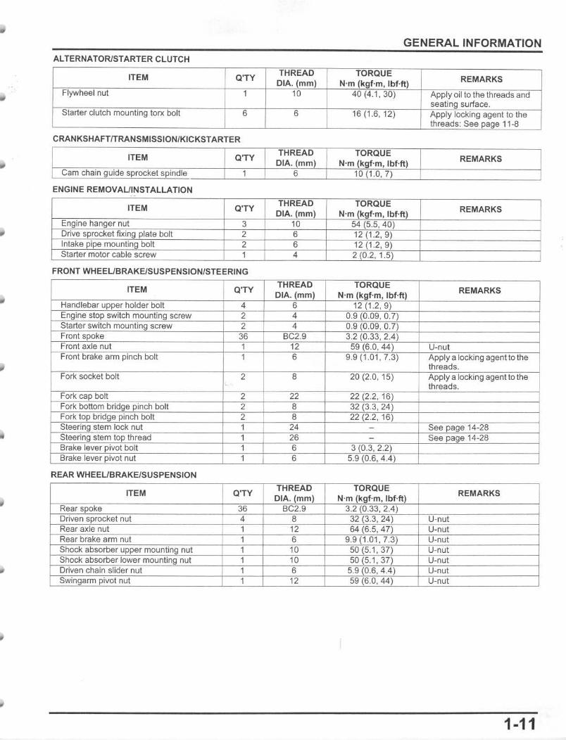
GENERAL INFORMATION ALTERNATORlSTARTER CLUTCH
ITEM C'TY THREAD TORQUE
REMARKS DIA.(mm) N'm (kgf'm, Ibf·ft) Flywheel nut 1 10 40 (4.1. 30) Apply oil to the threads and
seating surface. Starter clutch mounting torx boll 6 6 16 (1.6, 12) Apply locking agent to the
threads: See page 11-8
CRANKSHAFTfTRANSMISSION/KICKSTARTER
ITEM C'TY THREAD TORQUE I REMARKS DIA. (mm) N'm (kgf-m, lbHt)
Cam chain guide sprocket spindle 1 6 10 (1.0.7)
ENGINE REMOVAUINSTALLATION
ITEM C'TY REMARKS
FRONT WHEEUBRAKElSUSPENSION/STEERING
ITEM Q'TY DIA. (mm) N'm f~ " Ibf·ft)
REMARKS
b*QlneS~ 4 6 ~ ,
4 , , Fmnl spoke BC2.9
Fmn~m pinch bolt ~ U-nul
1 0 •.• (l.Ul . f.J) ~PPIY I
" 001t < • <U « .u, lO) ~PP'Y ,' locking olhe
D bolt T, Fo", bottorr bridge pinch bolt 2 8 ,24)
~g~ plncl bolt 2 8 -"" ' 16)
~'4-28 ' ostem~ Br.ke ,I bolt 3 (0.3, 2.2)
6 ~
REAR WHEEUBRAKE/SUSPENSIQN
ITEM Q'TY DIA.(mm) N'm" , Ibfft)
REMARKS
36 BC2.9 22_ 1,",2. , LJ::<UJ ,
g. 1.01. U-ne
I Driven chain slider nut ~ nul 10 "" · '-'" lJ:nUI.
· . · .
i n pivot nut I-ne
1-11
GENERAL INFORMATION
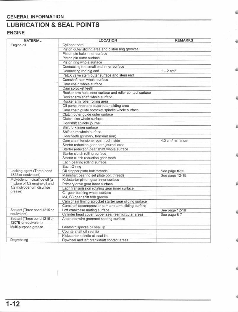
LUBRICATION & SEAL POINTS ENGINE
iii 1/2 engine oil and
1/2 molybdenum disulfide grease)
i I
1-12
Ii
II
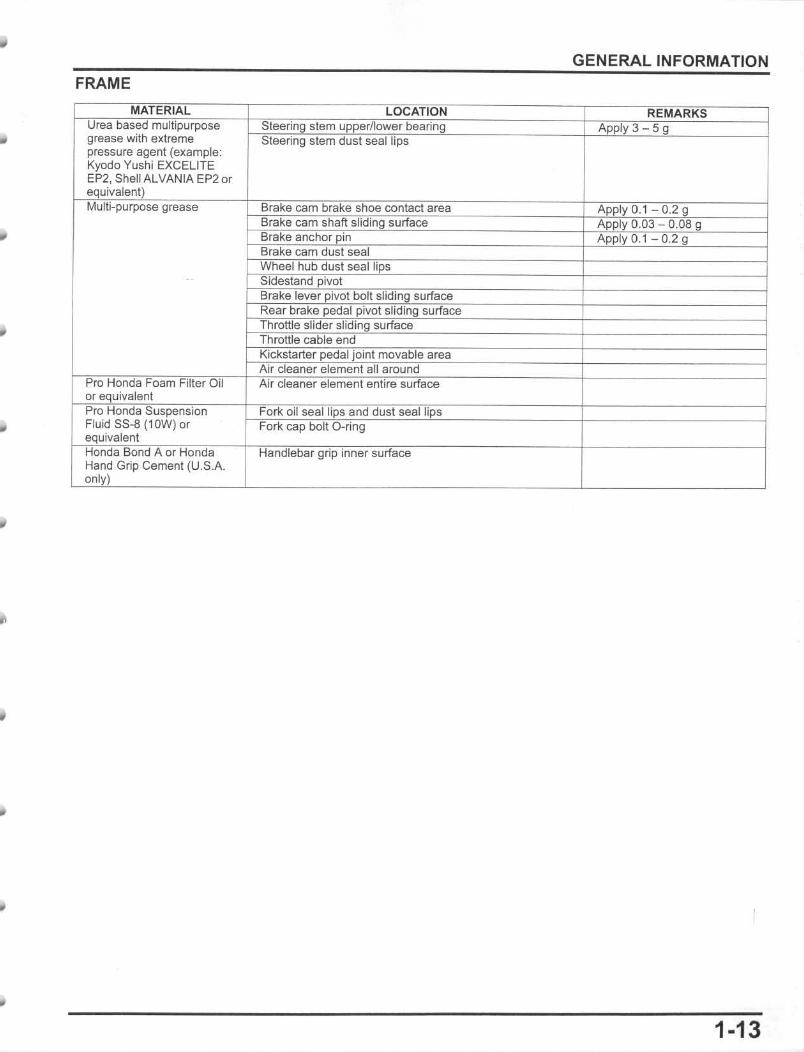
FRAME
grease with ext,c~me pressure agent (example: Kyodo Yushi EXCEUTE EP2, EP20r
Grip Cement (U.S.A.
GENERAL INFORMATION
H
1-13
GENERAL INFORMATION
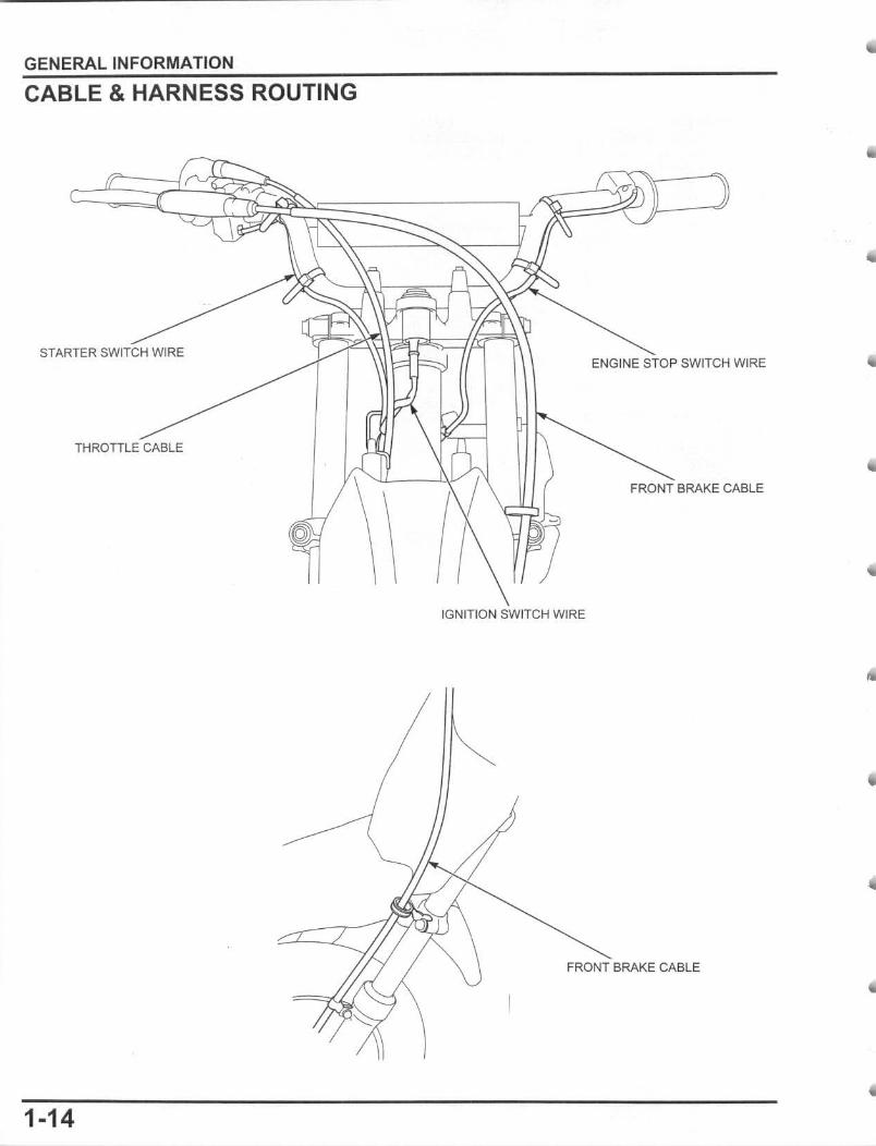
CABLE & HARNESS ROUTING
STARTER SWITCH WIRE ENGINE STOP SWITCH WIRE
THROTTLE CABLE
FRONT BRAKE CABLE
IGNITION SWITCH WIRE
FRONT BRAKE CABLE
1-14
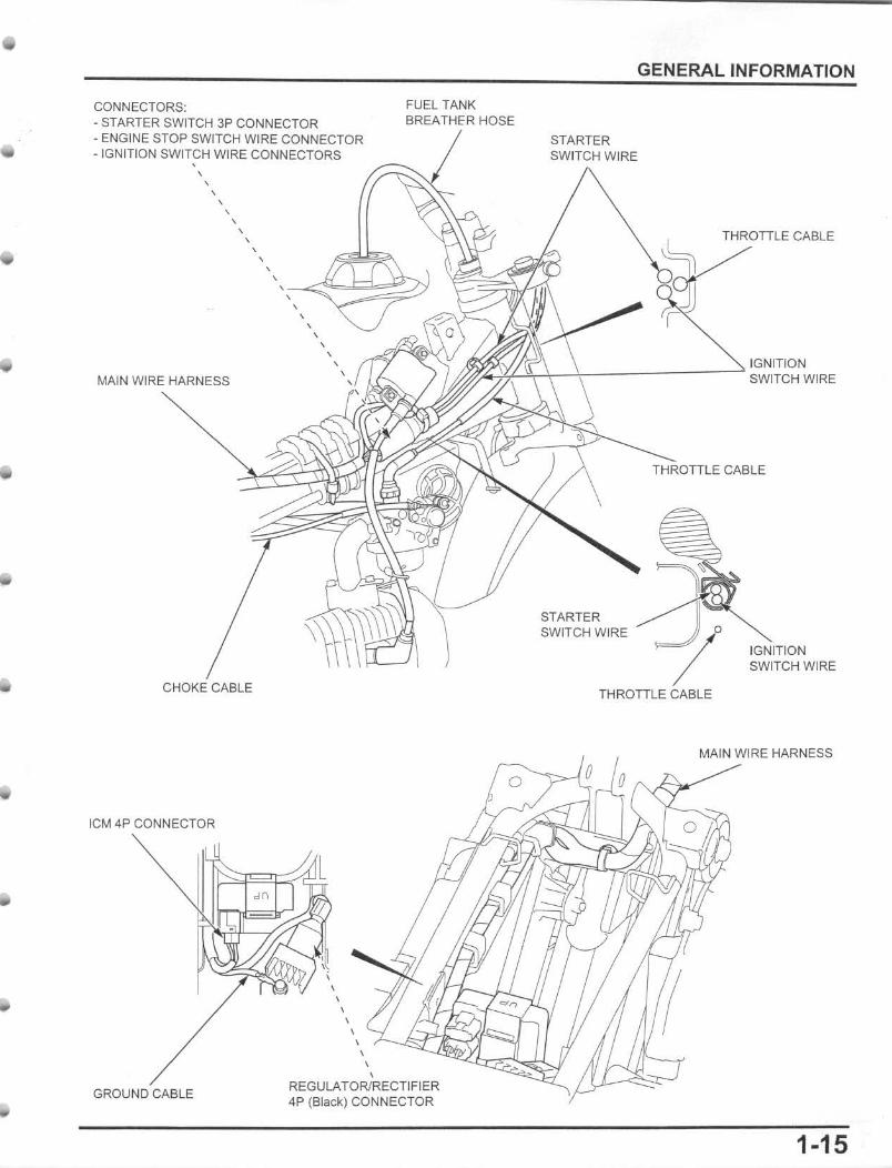
CONNECTORS; • STARTER SWITCH 3P CONNECTOR • ENGINE STOP SWITCH WIRE CONNECTOR • IGNITION SWITCH WIRE CONNECTORS , ,
, ,
MAIN WIRE HARNESS
, , ,
CHOKE CABLE
leM 4P CONNECTOR
, , , , , , , , , ,
, ,
GENERAL INFORMATION
FUEL TANK BREA THE'R HOSE
STARTER SWITCH WIRE
THROTTLE CABLE
~~~I,-J,--------':::' IGNITION ~ SWITCH WIRE
STARTER SWITCH WIRE
THROTTLE CABLE
CABLE
IGNITION SWITCH WIRE
MAIN WIRE HARNESS
, , ,~
GROUND CABLE
, REGULATOR/RECTIFIER 4P (Black) CONNECTOR
1-15
GENERAL INFORMATION
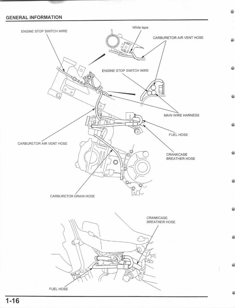
ENGINE STOP SWITCH WIRE
CARBURETOR AIR VENT HOSE
CARBURETOR DRAIN HOSE
FUEL HOSE
1-16
White tape
ENGINE STOP SWITCH WIRE
CARBURETOR AIR VENT HOSE
MAIN WIRE HARNESS
FUEL HOSE
CRANKCASE BREATHER HOSE
CRANKCASE BREATHER HOSE
STARTER MOTOR CABLE
o
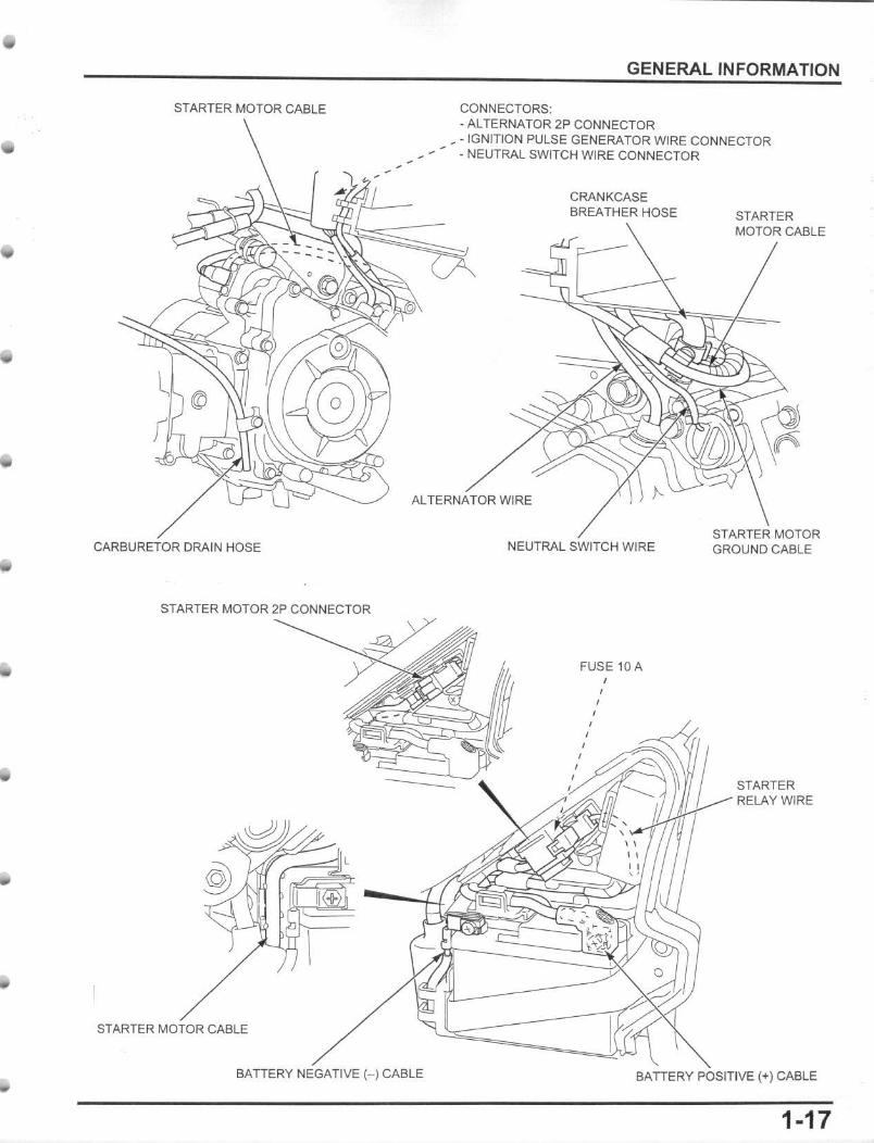
GENERAL INFORMATION
CONNECTORS: - ALTERNATOR 2P CONNECTOR
_ ·IGNJT!ON PULSE GENERATOR WIRE CONNECTOR • NEUTRAL SWITCH WIRE CONNECTOR
CRANKCASE BREATHER HOSE STARTER
MOTOR CABLE
ALTERNATOR WiRE
CARBURETOR DRAIN HOSE
STARTER MOTOR CABLE
BATTERY NEGATIVE H CABLE
NEUTRAL SWITCH WIRE
FUSE 10A
STARTER MOTOR GROUND CABLE
STARTER RELAY WIRE
BATTERY POSITIVE (+) CABLE
1·17
GENERAL INFORMATION
EMISSION CONTROL SYSTEMS The U.S. Environmental Protection Agency (EPA), and the California Air Resources Board (CARB) require that off-road motorcycles comply with applicable exhaust emissions standards during its useful life, when operated and maintained according to the instructions provided.
SOURCE OF EMISSIONS The combustion process produces oxides of nitrogen. carbon monoxide and hydrocarbons. Control of oxides of nitrogen and hydrocarbons is very important because, under certain conditions, they react to form photochemical smog when subjected to sunlight. Carbon monoxide does not react in the same way, but it is toxic.
Honda Motor Co., Ltd. utilizes appropriate carburetor settings as well as other systems, to reduce carbon monoxide and hydrocarbons.
EXHAUST EMISSION CONTROL SYSTEM The exhaust emission control sistem is composed of appropriate carburetor settings, no adjustment should be made except for high altitude setting and idle speed adjustment with the throttle stop screw. The exhaust emission control system is separate from the crankcase emission control system.
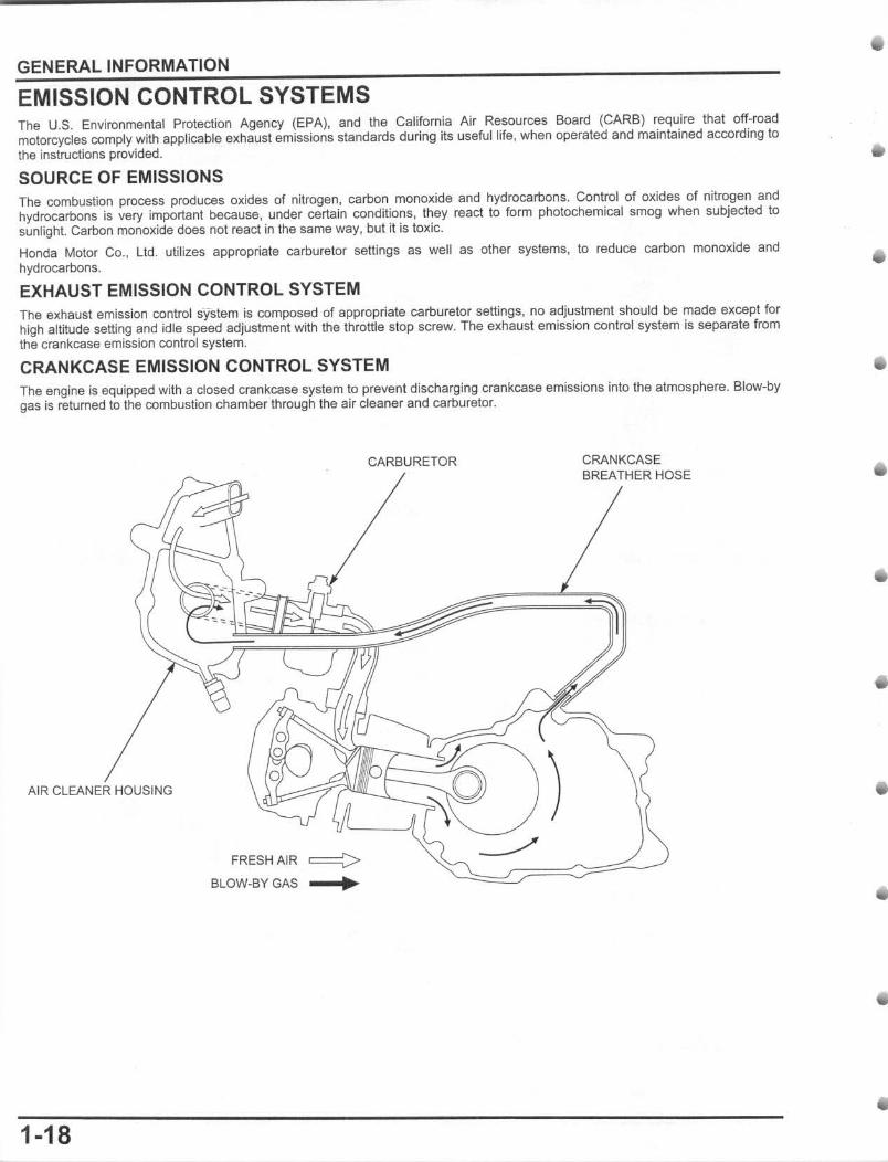
CRANKCASE EMISSION CONTROL SYSTEM The engine is equipped with a dosed crankcase system to prevent discharging crankcase emissions into the atmosphere. Blow-by gas is retumed to the combustion chamber through the air deaner and carburetor.
AIR CLEANER HOUSING
FRESH AJR c:=::;>-BLOW-BY GAS It
1-18
CARBURETOR CRANKCASE BREATHER HOSE
•
GENERAL INFORMATION
SERVICING THE Honda U.S.A. Only
Maintenance, replacement or repair of the emission control devices and systems may be performed by any motorcycle repair establishment or individual using parts Ihat are ~certified" to EPA standards.
PROHIBITED ACTIONS The following prohibitions apply to everyone with respect to the engines emission control system.
You may not remove or disable any device or element of design Ihat may affect an engine's emission levels. This restriction applies before and after the engine in placed in service.
Vehicles Ihal are used only for competition are exempt from this prohibition.
NOISE EMISSION CONTROL SYSTEM TAMPERING WITH THE NOISE CONTROL SYSTEM IS PROHIBITED: U.S. Federal law prohibits, or Canadian provincial law may prohibi t the following acts or the causing thereof: (1) the removal or rendering inoperative by any person, other than for purposes of maintenance, repair or replacement, of any device or element of design incorporated into any new vehicle for purpose of noise control prior to its sale or delivery to the ultimate purchaser or while it is in use; or (2) the use of the vehicle after such device or element of design has been removed or rendered inoperative by any person.
AMONG THOSE ACTS PRESUMED TO CONSTITUTE TAMPERING ARE THE ACTS LISTED BELOW: 1. Removal of, or puncturing of the muffler, baffles,header pipes or any other component which conducts exhaust gases. 2. Removal of, or puncturing of any part of the intake system. 3. Lack of proper maintenance. 4. Replacing any moving parts of the vehicle, or parts of the exhaust or intake system, with parts other than those specified by the
manufacturer.
FUEL PERMEATION EMISSION CONTROL SYSTEM This motorcycle complies with the Fuel Permeation Emission Control regulations of the U.S. Environmental Protecllon Agency (EPA). California Air Resources Board (CARB), and Environment Canada (EC). The fuel tank, fuel hoses, and fuel vapor charge hoses used on this motorcycle incorporate fuel permeation control technologies. Tampering with the fuel tank, fuel hoses, or fuel vapor charge hoses to reduce or defeat the effectiveness of the fuel permeation technologies is prohibited by federal regulations.
REBUILT ENGINE When you rebuild your engine including a major overhaul in which you replace the engine's pistons or power assemblies or make other changes that significantly increase the service tife of the engine, your Honda will continue to comply with all emissions regulations if you:
- Make sure you are technically qualified to rebuild the engine and have the proper tools - Use only Genuine Honda parts or equivalents - Make sure to maintain aU specifications as described in this Service Manual
1-19