1 help contents codeveloperä from impulse accelerated ...€¦ · tutorial€sample€projects...
TRANSCRIPT
Help Contents 1
© 2003-2015 Impulse Accelerated Technologies
1 Help Contents
CoDeveloperäfrom
Impulse Accelerated Technologiesä
Xilinxä MicroBlazeä Platform Support Package
Before You Begin (Read This First)
CoDeveloper Product OverviewPlatform Support Package Overview
Quick Start Tutorials
1.1 Xilinx MicroBlaze Platform Support Package Overview
Welcome to CoDeveloperä for Xilinx Platforms
Welcome to CoDeveloper: advanced software technologies enabling high-performance applications onprogrammable hardware platforms. CoDeveloper will change the way you create applications for XilinxFPGAs, and for MicroBlaze-based programmable platforms.
The complete CoDeveloper environment consists of a set of libraries allowing Impulse C applicationsto be executed in a standard C/C++ desktop compiler (for simulation and debugging purposes) as wellas cross-compiler and translation tools allowing mixed hardware/software applications to beimplemented on selected programmable hardware platforms including Xilinx FPGAs, with or withoutembedded microprocessors. Additional tools for application profiling and co-simulation with otherenvironments (including links to EDA tools for hardware simulation) are provided.
CoDeveloper is designed for use with leading tools for embedded software and programmablehardware development, including FPGA synthesis tools, desktop (Windows and Linux) C/C++development tools and embedded compiler and debugger tools. The Xilinx MicroBlaze PlatformSupport Package (described in this document) extends the power of CoDeveloper by providingautomated software/hardware generation for MicroBlaze-based programmable platforms.
Getting Started
CoDeveloper Xilinx MicroBlaze Platform Support Package2
© 2003-2015 Impulse Accelerated Technologies
To get started using CoDeveloper for Xilinx platforms, you should load one of thetutorial sample projects included in the Examples\Xilinx subdirectory of your CoDeveloper installation.These examples will help you to understand how to create and manage an Impulse C project inconjunction with the Xilinx-provided software and hardware.
To load a sample project, select Open Project from the Application Manager File menu, and navigateto the Examples\Xilinx subdirectory of the Impulse C installation directory. Select one of the sampleprojects and open the project file (identified by a .icProj file name extension) associated with thatproject. Be sure to review any Readme files included with the sample project.
Before starting with a CoDeveloper Example project, be sure you have reviewed the information in theRead This First section of this document. Also, please take time to familiarize yourself with the Xilinx-provided tools by going through one or more of the Xilinx-supplied ISE and/or EDK tutorials.
See Also
Help ContentsRead This FirstQuick Start Tutorial
1.1.1 Read This First
Release Notes
This is release 3 of CoDeveloper for Xilinx Platform Support Package, from Impulse AcceleratedTechnologies.
SYSTEM REQUIREMENTS
The following is required to make full use of the Xilinx Platform Support Package:
· PC with 1GHz or better clock speed· 512MB RAM· Windows 2000 or Windows XP
The following additional hardware and software is required for Tutorial 1: Complex FIR Filtering:
· Xilinx Virtex-5 ML501 Evaluation Platform (or equivalent FPGA reference board)· Xilinx ISE development tools, version 11.2 or newer· Xilinx EDK version 11.2 or newer (required for use with MicroBlaze processors, optional otherwise)· Optional: third party FPGA synthesis software supporting Xilinx FPGAs· Optional: third party HDL simulation software
PREREQUISITES
The information and tutorials included in this Platform Support Package assume that you havepreviously installed the Xilinx ISE software, and the MicroBlaze Development Kit (as supplied by Xilinx)and have familiarized yourself with their operation. If you have not done so, we strongly suggest thatyou begin by going through one or more of the simple design tutorials included with the Xilinx tools. Inparticular, if you intend to make use of the MicroBlaze processor, then you should be familiar with theprocess of generating a MicroBlaze-based platform (using the Xilinx Platform Studio tools),downloading that processor to an Xilinx FPGA and running a simple (C language) example on the

Help Contents 3
© 2003-2015 Impulse Accelerated Technologies
target.
The tutorials in this Platform Support Package also assume that you have read and understand theintroductory sections of the CoDeveloper User's Guide, which is installed with your CoDeveloperproduct and can be accessed from the CoDeveloper Help menu. In particular, you should take the timeto go through the tutorials provided with CoDeveloper so you have a good understanding of the front-end design flow including both desktop simulation and hardware compilation.
Note: the tutorials provided in this document are intended for illustrative purposes only. The stepsrequired to use CoDeveloper with a specific FPGA, embedded processor and board combination maydiffer somewhat from the steps described in these tutorials. Please take the time to familiarize yourselfwith your selected prototyping board and with the Xilinx tools prior to beginning.
GETTING STARTED
A number of example Impulse C projects targeting the Xilinx platform are included in this installation.To work with these examples:
1. Start the Impulse Application Manager by selecting Start -> Impulse Accelerated Technologies ->CoDeveloper -> Application Manager.
2. Select the Sample Projects tab in the CoDeveloper Start Page.
3. Navigate to any listed sample project.
Once you have a sample project open, you can review the Impulse C sample program, launch a VisualStudio, CodeWarrior or Dev-C++ project (for desktop simulation) or invoke the Impulse CoBuilder toprocess the sample application and generate output files. These steps are fully described in the QuickStart Tutorial included in this document.
See Also
Quick Start Tutorial
1.1.2 Contents
CoDeveloperäfrom
Impulse Accelerated Technologiesä
Xilinxä MicroBlazeä Platform Support Package
Before You Begin (Read This First)
CoDeveloper Product OverviewPlatform Support Package Overview
CoDeveloper Xilinx MicroBlaze Platform Support Package4
© 2003-2015 Impulse Accelerated Technologies
Quick Start Tutorials
1.2 Quick Start Tutorials
Overview
Impulse C can be used to generate hardware modules that are directly connected to an embeddedprocessor (such as the Xilinx MicroBlaze) or to other hardware elements that may have beendescribed using other design tools or techniques. As you have seen in earlier tutorials (found in theCoDeveloper primary Help information), the Impulse C programming model emphasizes the use ofdata streams, signals, and shared memories for process-to-process communication. These interfacescan be used to connect Impulse C processes to a wide variety of hardware devices and processors.
For embedded processors such as MicroBlaze, there are multiple possible ways to providecommunication between a software application running on the processor, and a hardware acceleratorrunning in the FPGA fabric. These include (among others):
· Using the PLB to create an Impulse C peripheral on a shared bus
· Using the FSL (Fast Simplex Link) to create a high-speed data stream
· Using shared memory
The following tutorials focus on data streaming applications, using both PLB and FSL. Shared memoryexamples are provided in your CoDeveloper product installation.
Using the Xilinx MicroBlaze Processor
This following tutorials will lead you step-by-step through the compilation, execution and RTLgeneration of your first Impulse C applications on the Xilinx MicroBlaze platform.
The tutorials that follow assume that you have previously gone through at least one of the tutorialsincluded in your standard CoDeveloper installation. It is also assumed that you are somewhat familiarwith the Xilinx ISE and Platform Studio (EDK) tools.
Note: Tutorials 1 use Xilinx EDK (Platform Studio) version 11.2i or later.
Tutorial 1: Complex FIR Filtering on EDK 10.1i
Using the "Generic" Xilinx FPGA Platforms
If you are not using an embedded MicroBlaze processor or the Xilinx Platform Studio (EDK) tools,then you will use CoDeveloper to generate logic (in the form of HDL output files) that is connected toother hardware modules or to external device pins, typically through the use of named ports. (SeeTutorial 4 in the CoDeveloper primary Help file for more information about co_port types.)
The following section describes how HDL files generated by CoDeveloper can be easily imported into

Help Contents 5
© 2003-2015 Impulse Accelerated Technologies
a Xilinx ISE project for synthesis. (These steps are similar for other synthesis and simulation tools,including the Synplicity Synplify Pro tools, Mentor's Modelsim, and others.)
Exporting Files to Xilinx ISE
See Also
Platform Support Package Overview
1.2.1 Exporting Files to Xilinx ISE
Overview
This introductory tutorial briefly describes how to export the hardware files generated by CoDeveloperto the Xilinx ISE environment. This information assumes that you are not generating a completehardware/software system (including a MicroBlaze processor) and are instead generating a singlehardware module for integration with other FPGA hardware elements. If you are using the MicroBlazeprocessor in your application, please refer instead to Tutorial 1.
Exporting CoDeveloper-Generated Files to the ISE Tools
Exporting files from CoDeveloper to ISE is straightforward, once you understand how to specify thelocation of the Impulse library files. Here's how it works:
When you generate hardware for your project, the generated HDL and related files are normally outputto the hw subdirectory of your project. This subdirectory contains the generated logic for your ImpulseC application, and also contains the Impulse library files, which are copied automatically duringhardware generation.
When creating an ISE project, the Impulse library files (which include impack.vhd, etc.) need to beassigned to the "impulse" library within ISE. When you do this, make sure the correct library files arebeing used. For example, don't copy the files from the CoDeveloper installation; instead, make surethe correct Platform Support Package has been selected when building (this is normally the XilinxGeneric package) and that the files being imported to ISE are from the generated hw subdirectory.
Here are the detailed steps:
1. Create a new Project in ISE (File -> New Project). Select the target device type and other options,give the project a name and save it to your local project directory, or to a new subdirectory withinyour project directory if you prefer. Do not specify the hw subdirectory as the Project Location;your ISE project files would be deleted by CoDeveloper when it cleans build files.
2. Create a new library by selecting Project -> New Source, and selecting VHDL Library as thesource type. Give the new library the name impulse and enter the hw/lib subdirectory in theLocation field.
3. Click Next and Finish to close the wizard, skipping the Add Existing Sources page.
4. Open the Library View in Project Navigator and right-click the vhdl/impulse library, the chooseAdd Source. Add all files from the hw/lib subdirectory to the library.

CoDeveloper Xilinx MicroBlaze Platform Support Package6
© 2003-2015 Impulse Accelerated Technologies
5. Add the other generated HDL files from the hw subdirectory to the library work. These files arenormally named xxxx_top.vhd and xxxx_comp.vhd, where xxxx refers to your Impulse Cproject name.
Your ISE project file is now ready for synthesis.
See Also
Tutorial 1: Hello World on the MicroBlaze platformTutorial 2: Complex FIR FilteringTutorial 3: Using uClinux
1.2.2 Tutorial 1: Complex FIR on EDK 11.2
Overview
This detailed tutorial will demonstrate how to use Impulse C to create, compile and optimize a digitalsignal processing (DSP) example for the MicroBlaze platform. We will also show how to make use ofthe Fast Simplex Link (FSL) bus provided in the MicroBlaze platform.
The goal of this application will be to compile the algorithm (a Complex FIR Filter function) onhardware on the FPGA. The MicroBlaze will be used to run test code (producer and consumerprocesses) that will pass text data into the algorithm and accept the results.
This example makes use of the Xilinx Virtex-5 ML501 Evaluation Platform. The board features is aVirtex-5 FPGA with a MicroBlaze soft processor. This tutorial also assumes you are using the XilinxEDK 11.2i (or later) development tools.
This tutorial will require approximately two hours to complete, including software run times.
Note: this tutorial is based on a sample DSP application developed by Bruce Karsten of Xilinx, Inc. Amore complete description of the algorithm can be found in the Impulse C User Guide. This tutorialassumes that you have are familiar with the basic steps involved in using the Xilinx EDK tools. Forbrevity this tutorial will omit some EDK details that are covered in introductory EDK and Impulse Ctutorials.
Note also that most of the detailed steps in this tutorial only need to be performed once, during theinitial creation of your MicroBlaze application. Subsequent changes to the application do not requirerepeating these steps.
Steps
Loading the Complex FIR ApplicationUnderstanding the Complex FIR ApplicationCompiling the Application for SimulationBuilding the Application for the Target PlatformExporting Files from CoDeveloper
Help Contents 7
© 2003-2015 Impulse Accelerated Technologies
Creating the Platform Using the Xilinx ToolsImporting the Generated HardwareGenerating the FPGA BitmapImporting the Application SoftwareRunning the Application
1.2.2.1 Loading the Complex FIR Application
Complex FIR Filter Tutorial for MicroBlaze, Step 1
To begin, start the CoDeveloper Application Manager by selecting from the Windows Start ->Programs -> Impulse Accelerated Technologies -> CoDeveloper Application Manager programgroup.
Note: this tutorial assumes that you have already read and understand the Complex FIR Filterexample and tutorial presented in the main CoDeveloper help file.
Open the Xilinx MicroBlaze ComplexFIR sample project by selecting Open Project from the Filemenu, or by clicking the Open Project toolbar button. Navigate to the.\ExamplesV3\Embedded\ComplexFIR_MicroBlaze\ directory within your CoDeveloper installation.(You may wish to copy this example to an alternate directory before beginning.) The project file is alsoavailable online at http://impulsec.com/ReadyToRun/. Opening the project will result in the display of awindow similar to the following:

CoDeveloper Xilinx MicroBlaze Platform Support Package8
© 2003-2015 Impulse Accelerated Technologies
Files included in the Complex FIR Filter project include:
Source files ComplexFilter.c, Filter_hw.c and Filter_sw.c - These source files represent thecomplete application, including the main() function, consumer and producer software processes anda single hardware process.
Header files ComplexFilter.h and Filter.h - function prototypes and definitions.
See Also
Understanding the Complex FIR Application
1.2.2.2 Understanding the Complex FIR Application
Complex FIR Filter Tutorial for MicroBlaze, Step 2
Before compiling the Complex FIR Filter application to hardware, let's first take a moment tounderstand its basic operation and the contents of the its primary source files, and in particularFilter_hw.c.
The specific process that we will be compiling to hardware is represented by the following function(located in Filter_hw.c):
Help Contents 9
© 2003-2015 Impulse Accelerated Technologies
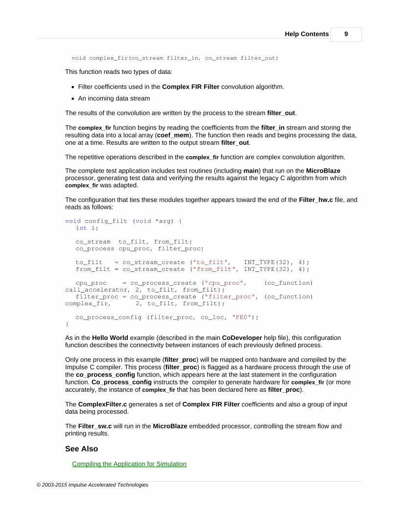
void complex_fir(co_stream filter_in, co_stream filter_out)
This function reads two types of data:
· Filter coefficients used in the Complex FIR Filter convolution algorithm.
· An incoming data stream
The results of the convolution are written by the process to the stream filter_out.
The complex_fir function begins by reading the coefficients from the filter_in stream and storing theresulting data into a local array (coef_mem). The function then reads and begins processing the data,one at a time. Results are written to the output stream filter_out.
The repetitive operations described in the complex_fir function are complex convolution algorithm.
The complete test application includes test routines (including main) that run on the MicroBlazeprocessor, generating test data and verifying the results against the legacy C algorithm from whichcomplex_fir was adapted.
The configuration that ties these modules together appears toward the end of the Filter_hw.c file, andreads as follows:
void config_filt (void *arg) {int i;
co_stream to_filt, from_filt;co_process cpu_proc, filter_proc;
to_filt = co_stream_create ("to_filt", INT_TYPE(32), 4);from_filt = co_stream_create ("from_filt", INT_TYPE(32), 4);
cpu_proc = co_process_create ("cpu_proc", (co_function)call_accelerator, 2, to_filt, from_filt);
filter_proc = co_process_create ("filter_proc", (co_function)complex_fir, 2, to_filt, from_filt);
co_process_config (filter_proc, co_loc, "PE0");}
As in the Hello World example (described in the main CoDeveloper help file), this configurationfunction describes the connectivity between instances of each previously defined process.
Only one process in this example (filter_proc) will be mapped onto hardware and compiled by theImpulse C compiler. This process (filter_proc) is flagged as a hardware process through the use ofthe co_process_config function, which appears here at the last statement in the configurationfunction. Co_process_config instructs the compiler to generate hardware for complex_fir (or moreaccurately, the instance of complex_fir that has been declared here as filter_proc).
The ComplexFilter.c generates a set of Complex FIR Filter coefficients and also a group of inputdata being processed.
The Filter_sw.c will run in the MicroBlaze embedded processor, controlling the stream flow andprinting results.
See Also
Compiling the Application for Simulation

CoDeveloper Xilinx MicroBlaze Platform Support Package10
© 2003-2015 Impulse Accelerated Technologies
1.2.2.3 Compiling the Application for Simulation
Complex FIR Filter Tutorial for MicroBlaze, Step 3
Simulation allows you to verify the correct operation and functional behavior of your algorithm beforeattempting to generate hardware for the FPGA. When using Impulse C, simulation simply refers to theprocess of compiling your C code to the desktop (host) development system using a standard Ccompiler, in this case the GCC compiler included with the Impulse CoDeveloper tools.
To compile and simulate the application for the purpose of functional verification:
1. Select Project -> Build Software Simulation Executable (or click the Build SoftwareSimulation Executable button) to build the FIR_Accelerator.exe executable. A commandwindow will open, displaying the compile and link messages as shown below:
2. You now have a Windows executable representing the Complex FIR Filter applicationimplemented as a desktop (console) software application. Run this executable by selectingProject -> Launch Simulation Executable. A command window will open and the simulationexecutable will run as shown below:
Verify that the simulation produces the output shown. Note that although the messages indicate thatthe ComplexFIR algorithm is running on the FPGA, the application (represented by hardware andsoftware processes) is actually running entirely in software as a compiled, native Windows executable.The messages you will see have been generated as a result of instrumenting the application withsimple printf statements such as the following:
#if defined(MICROBLAZE) xil_printf ("COMPLETE APPLICATION\r\n"); return 0;#else printf ("COMPLETE APPLICATION\r\n"); printf ("Press Enter to continue...\r\n"); c = getc(stdin);#endif
Help Contents 11
© 2003-2015 Impulse Accelerated Technologies
Notice in the above C source code that #ifdef statements have been used to allow the software side ofthe application to be compiled either for the embedded MicroBlaze processor, or to the hostdevelopment system for simulation purposes.
See Also
Building the Application for the Target Platform
1.2.2.4 Building the Application for the Target Platform
Complex FIR Filter Tutorial for MicroBlaze, Step 4
The next step in the tutorial is to create FPGA hardware and related files from the C code found in theFilter_hw.c source file. This requires that we select a platform target, specify any needed options, andinitiate the hardware compilation process.
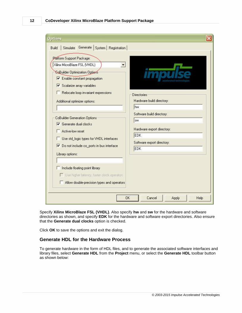
Specifying the Platform Support Package
To specify a platform target, open the Generate tab of the Options dialog as shown below:
CoDeveloper Xilinx MicroBlaze Platform Support Package12
© 2003-2015 Impulse Accelerated Technologies
Specify Xilinx MicroBlaze FSL (VHDL). Also specify hw and sw for the hardware and softwaredirectories as shown, and specify EDK for the hardware and software export directories. Also ensurethat the Generate dual clocks option is checked.
Click OK to save the options and exit the dialog.
Generate HDL for the Hardware Process
To generate hardware in the form of HDL files, and to generate the associated software interfaces andlibrary files, select Generate HDL from the Project menu, or select the Generate HDL toolbar buttonas shown below:

Help Contents 13
© 2003-2015 Impulse Accelerated Technologies
A series of processing steps will run in a command window as shown below:
Note: the processing of this example may require a few minutes to complete, depending on theperformance of your system.
When processing has completed you will have a number of resulting files created in the hw and swsubdirectories of your project directory.
See Also
Exporting Files from CoDeveloper
1.2.2.5 Exporting Files from CoDeveloper
Complex FIR Filter Tutorial for MicroBlaze, Step 5
Recall that in Step 4 you specified the directory EDK as the export target for hardware and software.These export directories specify where the generated hardware and software processes are to becopied when the Export Software and Export Hardware features of CoDeveloper are invoked.Within these target directories (in this case EDK), the specific destination (which may be a subdirectoryunder EDK) for each file previously generated is determined from the Platform Support Packagearchitecture library files. It is therefore important that the correct Platform Support Package (in thiscase Xilinx MicroBlaze FSL) is selected prior to starting the export process.
To export the files from the build directories (in this case hw and sw) to the export directories (in this

CoDeveloper Xilinx MicroBlaze Platform Support Package14
© 2003-2015 Impulse Accelerated Technologies
case the EDK directory), select Project -> Export Generated Hardware (HDL) and Project -> ExportGenerated Software, or select the Export Generated Hardware and Export Generated Softwarebuttons from the toolbar.
Export the Hardware Files
Export the Software Files
Note: you must select BOTH Export Software and Export Hardware before going onto the next step.
You have now exported all necessary files from CoDeveloper to the Xilinx tools environment.
See Also
Creating the Platform Using the Xilinx Tools
Help Contents 15
© 2003-2015 Impulse Accelerated Technologies
1.2.2.6 Creating a Platform Using Xilinx Tools
Complex FIR Filter Tutorial for MicroBlaze, Step 6
CoDeveloper creates a number of hardware and software-related output files that must all be used tocreate a complete hardware/software application on the target platform (in this case a Xilinx FPGA withan embedded MicroBlaze processor). This section will walk you through the file export/import processfor this example, using the EDK System Builder (Platform Studio) project.
Creating a New Xilinx Platform Studio Project
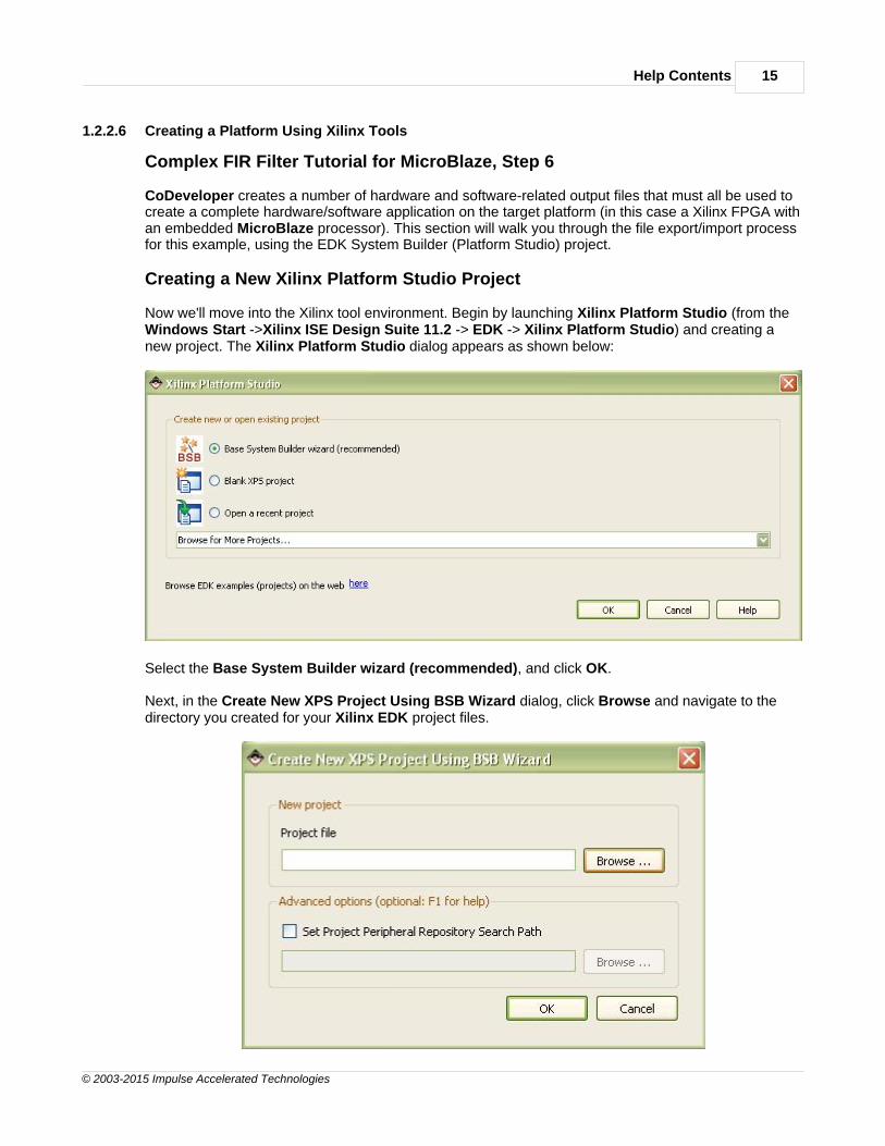
Now we'll move into the Xilinx tool environment. Begin by launching Xilinx Platform Studio (from theWindows Start ->Xilinx ISE Design Suite 11.2 -> EDK -> Xilinx Platform Studio) and creating anew project. The Xilinx Platform Studio dialog appears as shown below:
Select the Base System Builder wizard (recommended), and click OK.
Next, in the Create New XPS Project Using BSB Wizard dialog, click Browse and navigate to thedirectory you created for your Xilinx EDK project files.
CoDeveloper Xilinx MicroBlaze Platform Support Package16
© 2003-2015 Impulse Accelerated Technologies
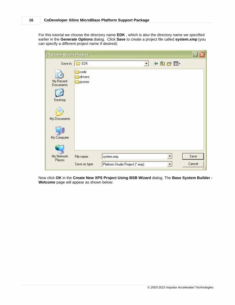
For this tutorial we choose the directory name EDK , which is also the directory name we specifiedearlier in the Generate Options dialog. Click Save to create a project file called system.xmp (youcan specify a different project name if desired):
Now click OK in the Create New XPS Project Using BSB Wizard dialog. The Base System Builder -Welcome page will appear as shown below:
Help Contents 17
© 2003-2015 Impulse Accelerated Technologies
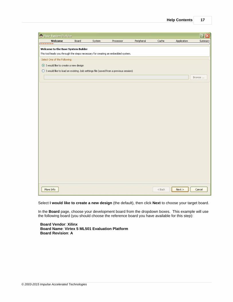
Select I would like to create a new design (the default), then click Next to choose your target board.
In the Board page, choose your development board from the dropdown boxes. This example will usethe following board (you should choose the reference board you have available for this step):
Board Vendor: Xilinx Board Name: Virtex 5 ML501 Evaluation Platform Board Revision: A

CoDeveloper Xilinx MicroBlaze Platform Support Package18
© 2003-2015 Impulse Accelerated Technologies
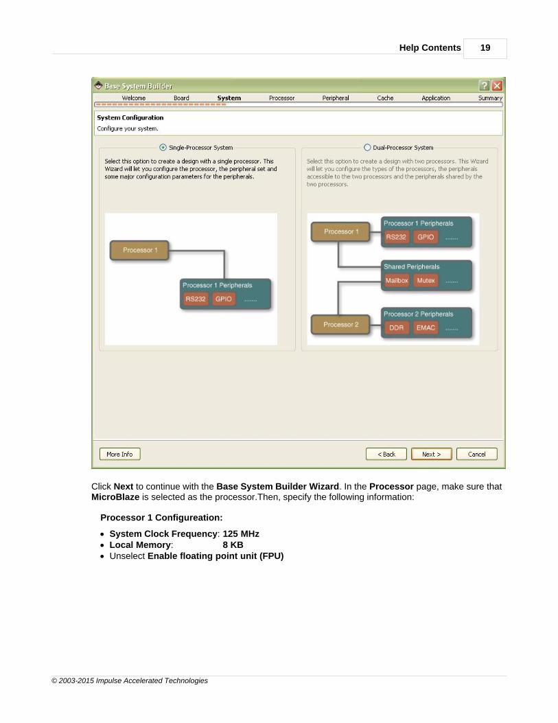
Click Next to continue with the Base System Builder Wizard. In the System page, choose the defaultSingle-Processor System:
Help Contents 19
© 2003-2015 Impulse Accelerated Technologies
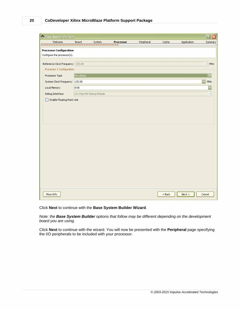
Click Next to continue with the Base System Builder Wizard. In the Processor page, make sure thatMicroBlaze is selected as the processor.Then, specify the following information:
Processor 1 Configureation:
· System Clock Frequency: 125 MHz· Local Memory: 8 KB· Unselect Enable floating point unit (FPU)
CoDeveloper Xilinx MicroBlaze Platform Support Package20
© 2003-2015 Impulse Accelerated Technologies
Click Next to continue with the Base System Builder Wizard.
Note: the Base System Builder options that follow may be different depending on the developmentboard you are using.
Click Next to continue with the wizard. You will now be presented with the Peripheral page specifyingthe I/O peripherals to be included with your processor.

Help Contents 21
© 2003-2015 Impulse Accelerated Technologies
Only a few peripherals are needed in this project. Remove the following items from the peripheral list:
· DIP_Switches_8Bit· Ethernet_MAC· IIC_EEPROM· LEDs_8Bit· LEDs_Positions· Push_Buttons_5Bit· SRAM· SysACE_CompactFlash
Next, add an xps_timer to the system. Select the xps_timer located at the bottom of the AvailablePeripherals on the left side. Click the Add> button to add the xps_timer. The xps_timer_0 appears inthe Peripherals list. Choose to the Configure mode as One timer is present, and do not Useinterrupt.

CoDeveloper Xilinx MicroBlaze Platform Support Package22
© 2003-2015 Impulse Accelerated Technologies
Click Next to turn to the next page.
In the Cache page, check both the Instruction Cache and Datat Cache as follows:

Help Contents 23
© 2003-2015 Impulse Accelerated Technologies
Click Next to turn to the next page.
On the Application dialog that appears, click OK to accept the default settings of the Memory Testand the Peripheral Test options:

CoDeveloper Xilinx MicroBlaze Platform Support Package24
© 2003-2015 Impulse Accelerated Technologies
You have now configured the platform and processor features. The Base System Builder Wizarddisplays a summary of the system you have created:

Help Contents 25
© 2003-2015 Impulse Accelerated Technologies
Click Finish to close the wizard and generate the system and project files. After this is done, theSystem Assembly View of the Platform Studio should look like this:

CoDeveloper Xilinx MicroBlaze Platform Support Package26
© 2003-2015 Impulse Accelerated Technologies
See Also
Importing the Generated Hardware
1.2.2.7 Importing the Generated Hardware
Complex FIR Filter Tutorial for MicroBlaze, Step 7
You will now create the target platform in the Xilinx Platform Studio. This procedure is somewhatlengthy but will only need to be done once for any new project.
Adding the ComplexFIR Hardware IP Core
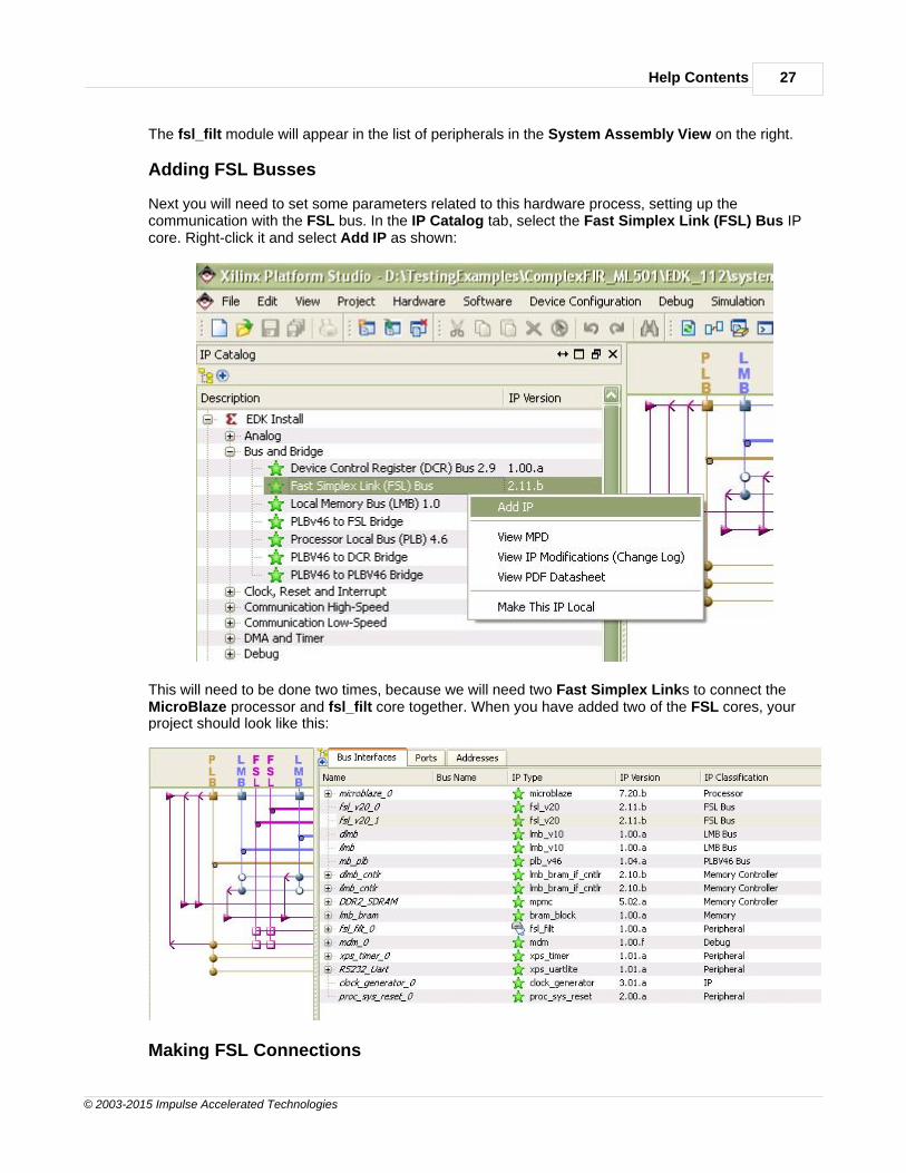
Next, add the module representing the ComplexFIR Filter hardware process to your developmentsystem. Switch to the IP Catalog tab in the Project Information Area. Select the Project Localpcores -> USER in the IP Catalog tab on the left. Right-click fsl_filt and select Add IP as shown.
Help Contents 27
© 2003-2015 Impulse Accelerated Technologies
The fsl_filt module will appear in the list of peripherals in the System Assembly View on the right.
Adding FSL Busses
Next you will need to set some parameters related to this hardware process, setting up thecommunication with the FSL bus. In the IP Catalog tab, select the Fast Simplex Link (FSL) Bus IPcore. Right-click it and select Add IP as shown:
This will need to be done two times, because we will need two Fast Simplex Links to connect theMicroBlaze processor and fsl_filt core together. When you have added two of the FSL cores, yourproject should look like this:
Making FSL Connections

CoDeveloper Xilinx MicroBlaze Platform Support Package28
© 2003-2015 Impulse Accelerated Technologies
The microblaze_0 module needs to be configured in order to link to two FSL links. Right-click onmicroblaze_0 and select Configure IP as shown:
Go to the Bus Interfaces tab and change Number of FSL Links to 2 as shown:
Click OK. Now we just need to connect the microblaze_0 to the fsl_filt_0 with the two new FSL links.
Help Contents 29
© 2003-2015 Impulse Accelerated Technologies
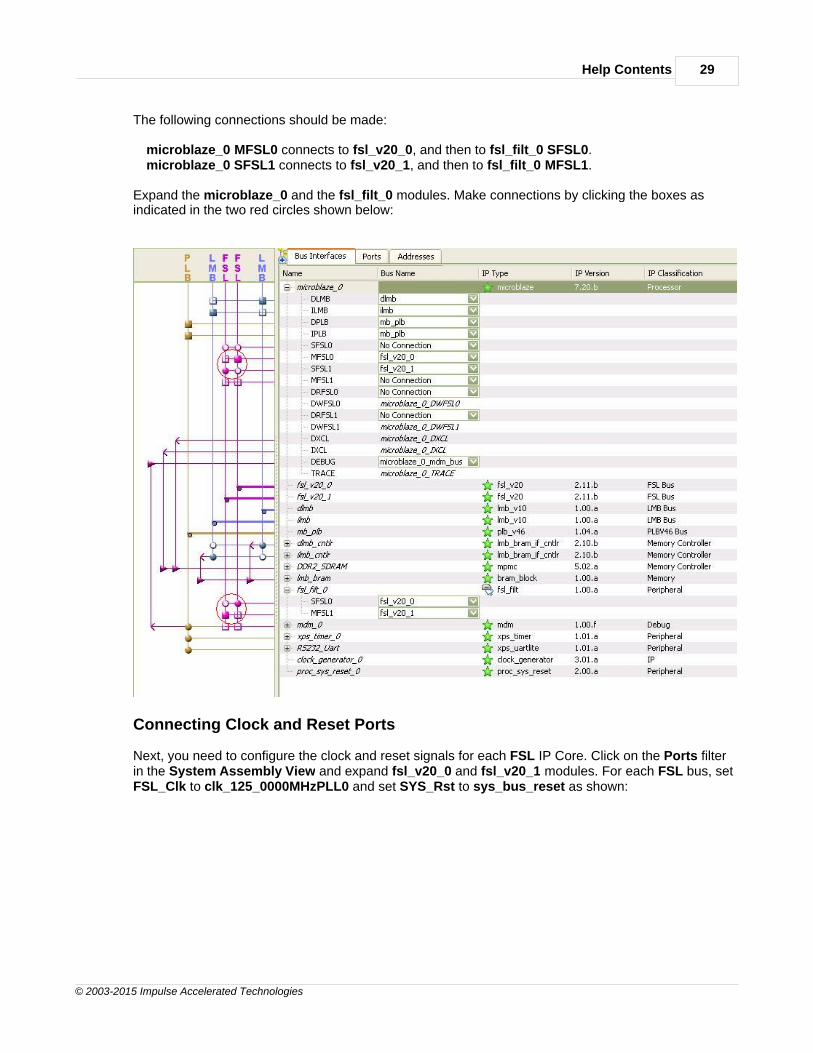
The following connections should be made:
microblaze_0 MFSL0 connects to fsl_v20_0, and then to fsl_filt_0 SFSL0.microblaze_0 SFSL1 connects to fsl_v20_1, and then to fsl_filt_0 MFSL1.
Expand the microblaze_0 and the fsl_filt_0 modules. Make connections by clicking the boxes asindicated in the two red circles shown below:
Connecting Clock and Reset Ports
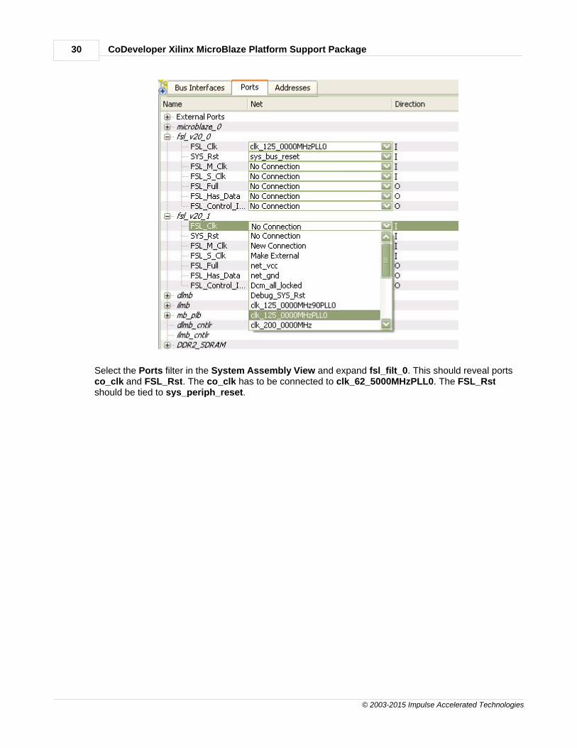
Next, you need to configure the clock and reset signals for each FSL IP Core. Click on the Ports filterin the System Assembly View and expand fsl_v20_0 and fsl_v20_1 modules. For each FSL bus, setFSL_Clk to clk_125_0000MHzPLL0 and set SYS_Rst to sys_bus_reset as shown:
CoDeveloper Xilinx MicroBlaze Platform Support Package30
© 2003-2015 Impulse Accelerated Technologies
Select the Ports filter in the System Assembly View and expand fsl_filt_0. This should reveal portsco_clk and FSL_Rst. The co_clk has to be connected to clk_62_5000MHzPLL0. The FSL_Rstshould be tied to sys_periph_reset.

Help Contents 31
© 2003-2015 Impulse Accelerated Technologies
Note: if co_clk is missing from the fsl_filt_0 section, then will need to return to step 4 of this tutorialand specify the Dual Clock option in the CoDeveloper Generate Options page.
Specify the Addresses
Now you will need to set the addresses for each of the peripherals specified for the platform. This canbe done simply by selecting the Addresses tab and clicking on the Generate Addresses button. Theaddresses will be assigned for you automatically:
You have now exported all necessary hardware files from CoDeveloper to the Xilinx toolsenvironment and have configured your new platform. The next step will be to generate FPGAbitstream.
See Also
Generating the FPGA Bitmap
CoDeveloper Xilinx MicroBlaze Platform Support Package32
© 2003-2015 Impulse Accelerated Technologies
1.2.2.8 Generating the FPGA Bitmap
Complex FIR Filter Tutorial for MicroBlaze, Step 8
At this point, if you have followed the tutorial steps carefully you have successfully:
· Generated hardware and software files from the CoDeveloper environment.
· Created a new Xilinx Platform Studio project and created a new MicroBlaze-based platform.
· Imported your CoDeveloper-generated files to the Xilinx Platform Studio environment.
· Connected and configured the Impulse C hardware process to the MicroBlaze processor via theFSL bus.
You are now ready to generate the bitmap.
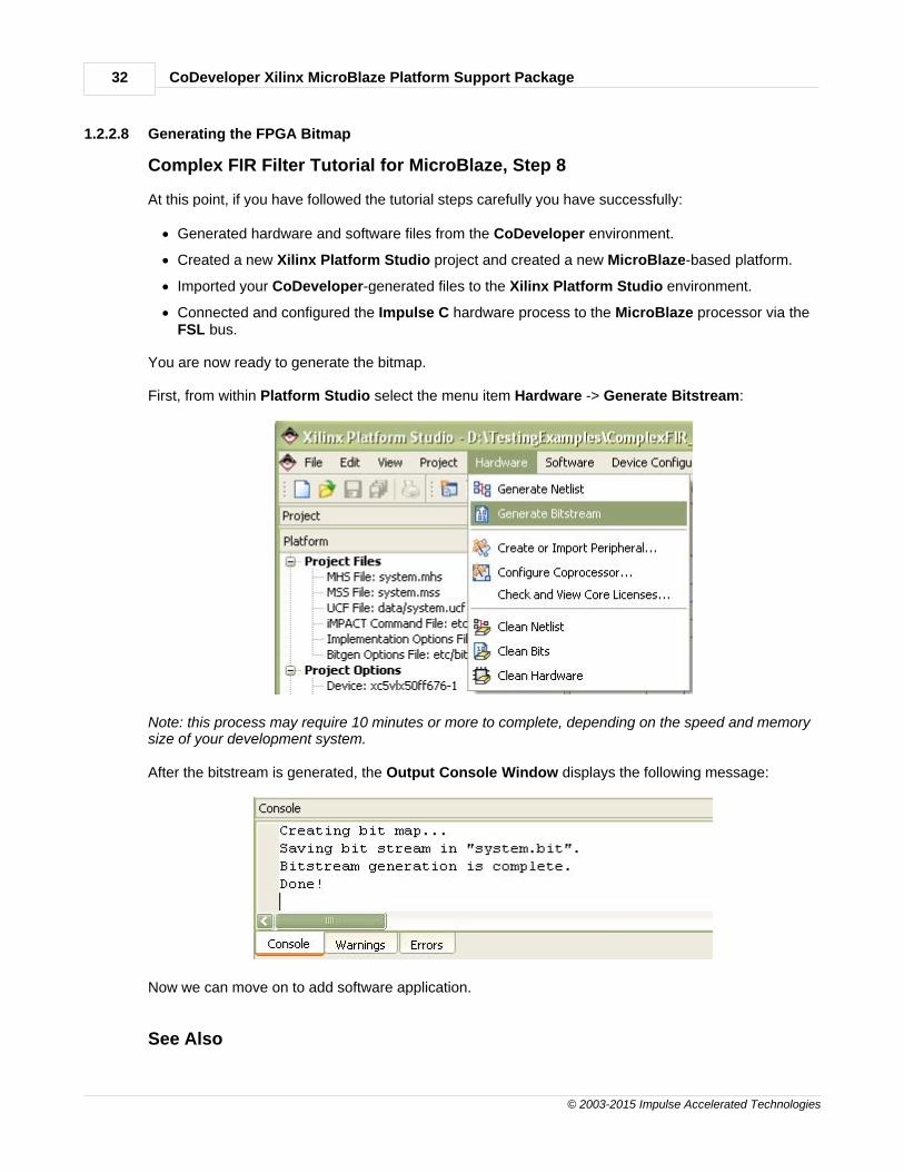
First, from within Platform Studio select the menu item Hardware -> Generate Bitstream:
Note: this process may require 10 minutes or more to complete, depending on the speed and memorysize of your development system.
After the bitstream is generated, the Output Console Window displays the following message:
Now we can move on to add software application.
See Also

Help Contents 33
© 2003-2015 Impulse Accelerated Technologies
Importing the Application Software
1.2.2.9 Importing the Application Software
Complex FIR Filter Tutorial for MicroBlaze, Step 9
You will now import the relevant software source files to your new Xilinx Platform Studio project.
On the Applications tab of the Project Information Area, create a new software project by double-clicking Add Software Application Project...
Type in the project name: filter.
Click OK to exit.
A new project filter is added to the project list. Right-click Sources under Project: filter and selectAdd Existing Files. A file selection dialog appears. Enter the code directory, and select all the C filesare shown below:

CoDeveloper Xilinx MicroBlaze Platform Support Package34
© 2003-2015 Impulse Accelerated Technologies
Click Open to add the source files shown to your project. These files comprise the software applicationthat will run on the MicroBlaze CPU.
Next, right-click Headers and select Add Existing Files. A file selection dialog appears. Enter thecode directory and select all three header files shown below. Click Open to add the files shown to yourproject.

Help Contents 35
© 2003-2015 Impulse Accelerated Technologies
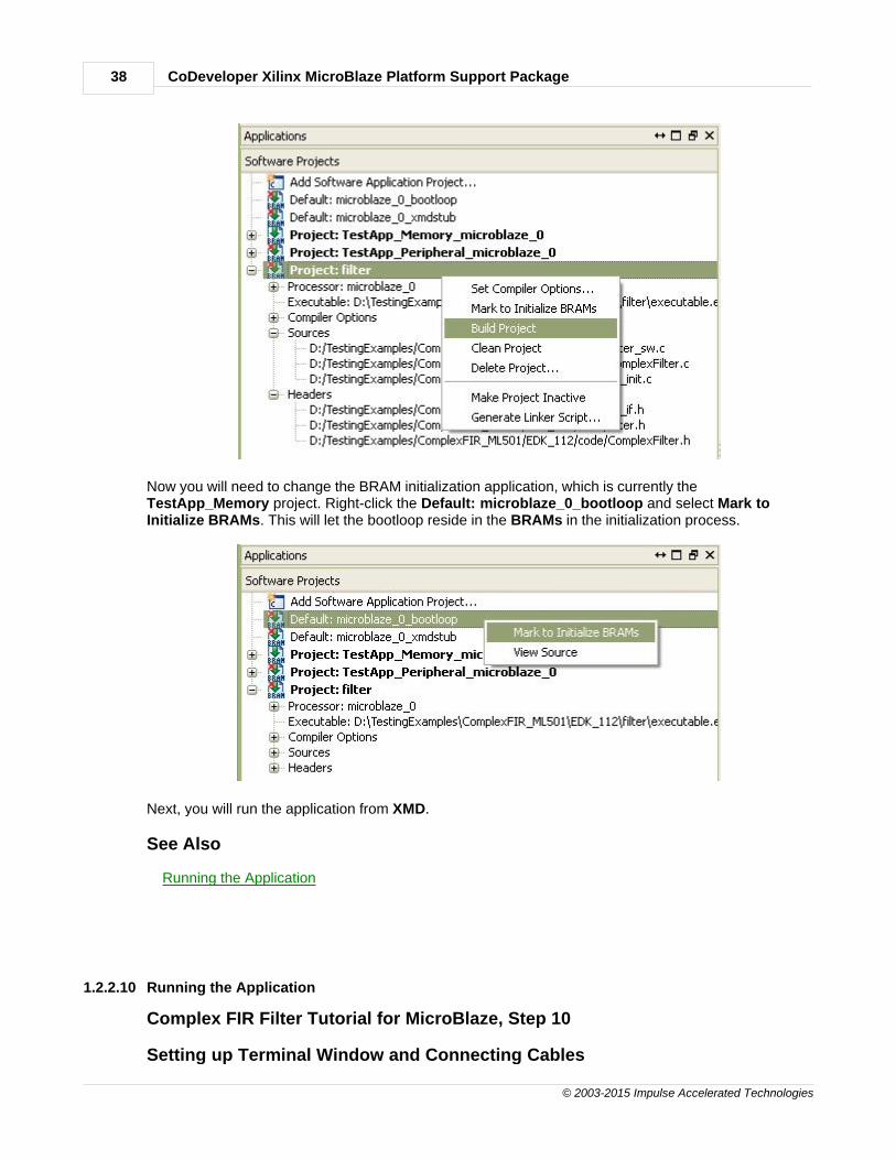
After you are done with adding files to the ComplexFIR project, right-click Project: ComplexFIR andselect Build Project.
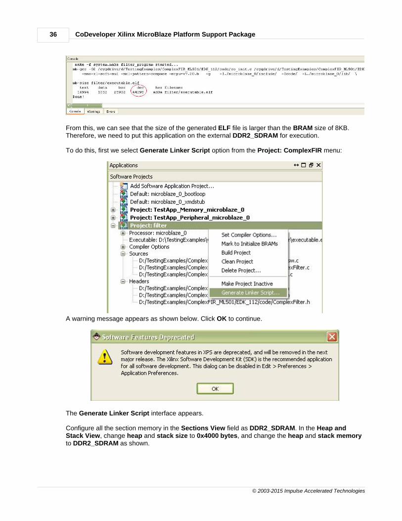
You will now see the following messages in the Console Window Output:
CoDeveloper Xilinx MicroBlaze Platform Support Package36
© 2003-2015 Impulse Accelerated Technologies
From this, we can see that the size of the generated ELF file is larger than the BRAM size of 8KB.Therefore, we need to put this application on the external DDR2_SDRAM for execution.
To do this, first we select Generate Linker Script option from the Project: ComplexFIR menu:
A warning message appears as shown below. Click OK to continue.
The Generate Linker Script interface appears.
Configure all the section memory in the Sections View field as DDR2_SDRAM. In the Heap andStack View, change heap and stack size to 0x4000 bytes, and change the heap and stack memoryto DDR2_SDRAM as shown.

Help Contents 37
© 2003-2015 Impulse Accelerated Technologies
Click OK to generate the linker script.
Now you will need to rebuild the project to reflect the changes in section mapping.
CoDeveloper Xilinx MicroBlaze Platform Support Package38
© 2003-2015 Impulse Accelerated Technologies
Now you will need to change the BRAM initialization application, which is currently theTestApp_Memory project. Right-click the Default: microblaze_0_bootloop and select Mark toInitialize BRAMs. This will let the bootloop reside in the BRAMs in the initialization process.
Next, you will run the application from XMD.
See Also
Running the Application
1.2.2.10 Running the Application
Complex FIR Filter Tutorial for MicroBlaze, Step 10
Setting up Terminal Window and Connecting Cables

Help Contents 39
© 2003-2015 Impulse Accelerated Technologies
Now let's run the application on the development board.
Connect the serial port of your development machine to that of your development board via a RS232cable. Make sure the JTAG download cable is connected on the development board. Also ensure thatthe board is configured to be programmed. Turn on the power to the board.
Open Tera Term or Windows HyperTerminal application to display the UART output message. Usethe same communication settings you chose when defining the RS232_Uart_1 peripheral in BaseSystem Builder (9600 baud, 8-N-1). Turn off flow control, if available.
Now, download the bitstream to the device by selecting Device Configuration -> DownloadBitstream as shown below:
When downloading is done, the Console window output will be similar to this:

CoDeveloper Xilinx MicroBlaze Platform Support Package40
© 2003-2015 Impulse Accelerated Technologies
Running Application from XMD
Now let's run the application on the development board.
Select from menu Debug -> Launch XMD...
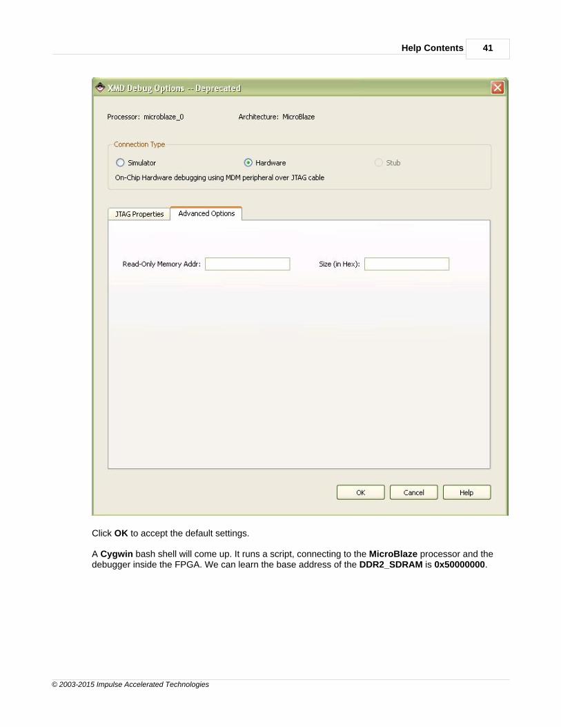
The XMD Debug Options dialog will appear for the first time opening XMD.
Help Contents 41
© 2003-2015 Impulse Accelerated Technologies
Click OK to accept the default settings.
A Cygwin bash shell will come up. It runs a script, connecting to the MicroBlaze processor and thedebugger inside the FPGA. We can learn the base address of the DDR2_SDRAM is 0x50000000.
CoDeveloper Xilinx MicroBlaze Platform Support Package42
© 2003-2015 Impulse Accelerated Technologies
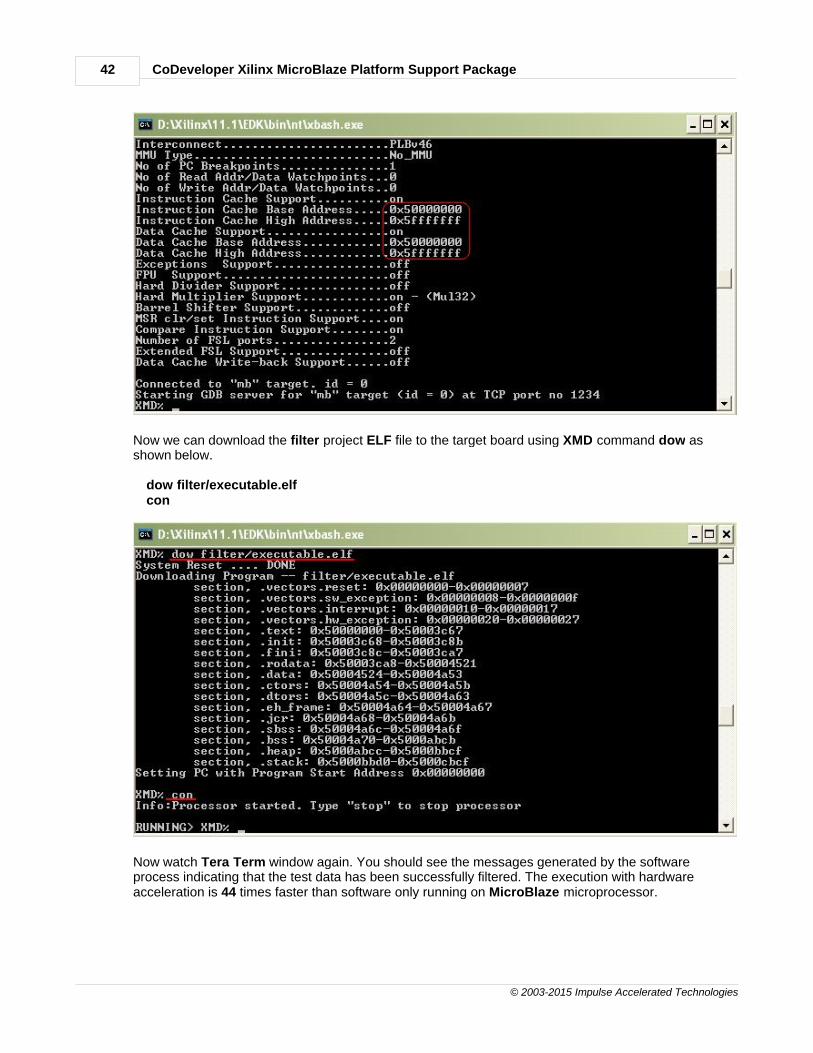
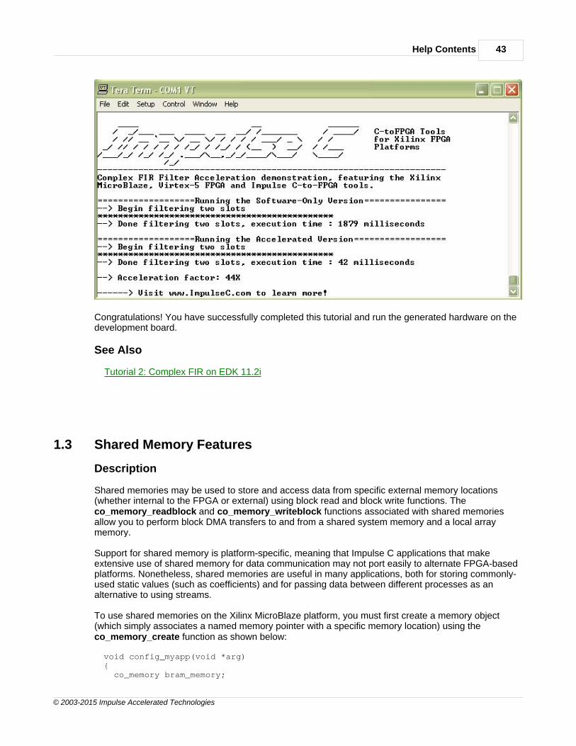
Now we can download the filter project ELF file to the target board using XMD command dow asshown below.
dow filter/executable.elfcon
Now watch Tera Term window again. You should see the messages generated by the softwareprocess indicating that the test data has been successfully filtered. The execution with hardwareacceleration is 44 times faster than software only running on MicroBlaze microprocessor.
Help Contents 43
© 2003-2015 Impulse Accelerated Technologies
Congratulations! You have successfully completed this tutorial and run the generated hardware on thedevelopment board.
See Also
Tutorial 2: Complex FIR on EDK 11.2i
1.3 Shared Memory Features
Description
Shared memories may be used to store and access data from specific external memory locations(whether internal to the FPGA or external) using block read and block write functions. Theco_memory_readblock and co_memory_writeblock functions associated with shared memoriesallow you to perform block DMA transfers to and from a shared system memory and a local arraymemory.
Support for shared memory is platform-specific, meaning that Impulse C applications that makeextensive use of shared memory for data communication may not port easily to alternate FPGA-basedplatforms. Nonetheless, shared memories are useful in many applications, both for storing commonly-used static values (such as coefficients) and for passing data between different processes as analternative to using streams.
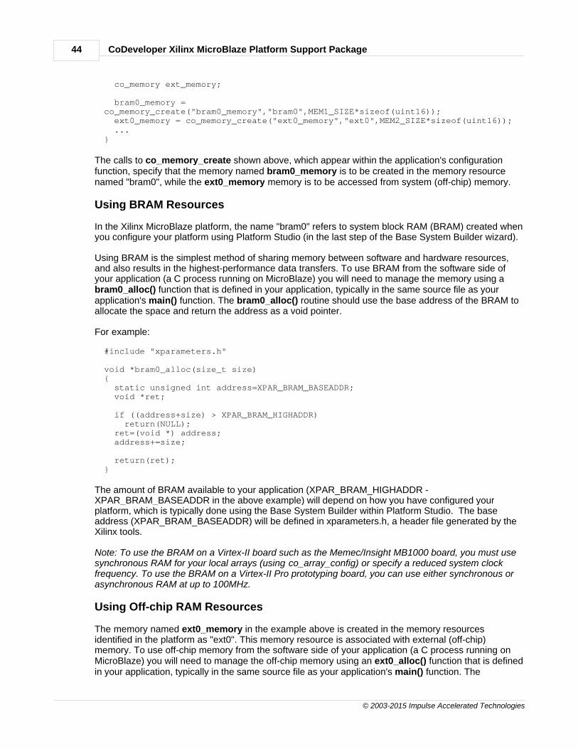
To use shared memories on the Xilinx MicroBlaze platform, you must first create a memory object(which simply associates a named memory pointer with a specific memory location) using theco_memory_create function as shown below:
void config_myapp(void *arg){ co_memory bram_memory;
CoDeveloper Xilinx MicroBlaze Platform Support Package44
© 2003-2015 Impulse Accelerated Technologies
co_memory ext_memory;
bram0_memory =co_memory_create("bram0_memory","bram0",MEM1_SIZE*sizeof(uint16)); ext0_memory = co_memory_create("ext0_memory","ext0",MEM2_SIZE*sizeof(uint16)); ...}
The calls to co_memory_create shown above, which appear within the application's configurationfunction, specify that the memory named bram0_memory is to be created in the memory resourcenamed "bram0", while the ext0_memory memory is to be accessed from system (off-chip) memory.
Using BRAM Resources
In the Xilinx MicroBlaze platform, the name "bram0" refers to system block RAM (BRAM) created whenyou configure your platform using Platform Studio (in the last step of the Base System Builder wizard).
Using BRAM is the simplest method of sharing memory between software and hardware resources,and also results in the highest-performance data transfers. To use BRAM from the software side ofyour application (a C process running on MicroBlaze) you will need to manage the memory using abram0_alloc() function that is defined in your application, typically in the same source file as yourapplication's main() function. The bram0_alloc() routine should use the base address of the BRAM toallocate the space and return the address as a void pointer.
For example:
#include "xparameters.h"
void *bram0_alloc(size_t size){ static unsigned int address=XPAR_BRAM_BASEADDR; void *ret;
if ((address+size) > XPAR_BRAM_HIGHADDR) return(NULL); ret=(void *) address; address+=size;
return(ret);}
The amount of BRAM available to your application (XPAR_BRAM_HIGHADDR -XPAR_BRAM_BASEADDR in the above example) will depend on how you have configured yourplatform, which is typically done using the Base System Builder within Platform Studio. The baseaddress (XPAR_BRAM_BASEADDR) will be defined in xparameters.h, a header file generated by theXilinx tools.
Note: To use the BRAM on a Virtex-II board such as the Memec/Insight MB1000 board, you must usesynchronous RAM for your local arrays (using co_array_config) or specify a reduced system clockfrequency. To use the BRAM on a Virtex-II Pro prototyping board, you can use either synchronous orasynchronous RAM at up to 100MHz.
Using Off-chip RAM Resources
The memory named ext0_memory in the example above is created in the memory resourcesidentified in the platform as "ext0". This memory resource is associated with external (off-chip)memory. To use off-chip memory from the software side of your application (a C process running onMicroBlaze) you will need to manage the off-chip memory using an ext0_alloc() function that is definedin your application, typically in the same source file as your application's main() function. The

Help Contents 45
© 2003-2015 Impulse Accelerated Technologies
ext0_alloc() routine should use the base address of the off-chip memory (as defined in xparameters.h)to allocate the space and return the address as a void pointer.
For example:
#include "xparameters.h"
void *ext0_alloc(size_t size){ static unsigned int address=XPAR_MYDDR_BASEADDR; void *ret;
if ((address+size)>XPAR_MYDDR_HIGHADDR) return(NULL); ret=(void *) address; address+=size;
return(ret);}
Note: Using DDR memory for block reads and writes will result in a maximum operating frequency foryour process of 75MHz.
Performance Considerations
Xilinx users must be aware that the CPU has priority over other bus masters, and any OPB activityfrom the CPU will significantly impact hardware processes' access to shared memory. For this reasonyou should restrict your use of shared memory transfers to non-performance-critical functions (such asloading initialization values).
The following chart describes the maximum system clock rates allowed for transfers between localarray memory and BRAM or off-chip memories for the Virtex-II and Virtex-II Pro platforms:
Transfer type Virtex-II Virtex-II Pro
Off-chip to/from synchronous array RAM 75 MHz 75 MHz
BRAM to/from synchronous array RAM 100 MHz 100 MHz
Off chip to/from asynchronous array RAM 75 MHz 75 MHz
BRAM to/from asynchronous array RAM 75 MHz 100 MHz
Choosing an External Memory
The choice of which external memory device to store data in is important to achieving the bestperformance for an application. External memories may differ in size, performance characteristics,and how they are connected in the FPGA-based system. Which memories are available depends onthe choice of Platform Support Package, as well as on which physical hardware platform is being used.
Platform Support Packages specify which memory locations are available to the programmer. Thelocation of a shared memory resource is chosen by the programmer using the co_memory_createfunction.
Memory locations supported by Xilinx/MicroBlaze-based platforms (Virtex-II Pro, Virtex-4, and Virtex-5)include:

CoDeveloper Xilinx MicroBlaze Platform Support Package46
© 2003-2015 Impulse Accelerated Technologies
Location Bus Description
ext0 OPB Any memory connected to the OPB bus
opbmem OPB Any memory connected to the OPB bus
bram0 Local Memory Bus (LMB) Block RAM created using EDK's Base SystemBuilder
"" (empty string) Default: opbmem
If an invalid memory location is specified, the Impulse C compiler will print an error, and indicate whichmemory locations are supported for the chosen platform:
"C:/Impulse/CoDeveloper3/bin/impulse_arch" "-aC:/Impulse/CoDeveloper3/Architectures/xilinx_mb_fsl.xml" -no_port_bus_connect -swdirsw -files "Mandelbrot_comp.vhd Mandelbrot_top.vhd " Mandelbrot.xichw/Mandelbrot_top.vhdImpulse C HDL Design GeneratorCopyright 2002-2007, Impulse Accelerated Technologies, Inc.All rights reserved.Loading C:/Impulse/CoDeveloper3/Architectures/xilinx_mb_fsl.xml ...LoadingC:/Impulse/CoDeveloper3/Architectures/VHDL/Xilinx/FSL/bus.xml ...Loading C:/Impulse/CoDeveloper3/Architectures/VHDL/target.xml ...Loading C:/Impulse/CoDeveloper3/Architectures/VHDL/Xilinx/technology.xml ...Loading C:/Impulse/CoDeveloper3/Architectures/Xilinx/MicroBlaze/FSL/standalone.xml...Loading C:/Impulse/CoDeveloper3/Architectures/VHDL/Xilinx/OPB/bus.xml ...Loading Mandelbrot.xic ...Undefined memory: mem0The following memories are defined for this platform: opbmem ext0make: *** [hw/Mandelbrot_top.vhd] Error 1
See Also
Configuring Local ArraysQuick Start Tutorials
1.4 Platform Support Package Overview
Overview
Platform Support Packages (or PSPs) are optional packages that provide platform-specific libraries,examples and documentation for Impulse C users. Platform support packages simplify the creation ofmixed software/hardware applications by providing you with the necessaryhardware/software interfaces for both the hardware (FPGA) and software (microprocessor) elementsof the platform.
What is a Platform?
A platform is a specific combination of hardware and software components that can be used to run anImpulse C application. A platform may be a board-level system that includes one or more externalprocessors combined with an off-the-shelf FPGA, or it may be a single-chip system that utilizes anembedded (or "soft") processor within a larger FPGA. A given platform may also be defined by the typeof bus it uses to connect the processor and FPGA, the type(s) of memories available in the system andother factors such as whether an operating system will be involved. A typical platform is defined by:
· The family of FPGA being used to implemented hardware processes
Help Contents 47
© 2003-2015 Impulse Accelerated Technologies
· The type of embedded microprocessor being used to implement software processes
· The type of bus used to communicate data in the hardware/software system
· The type and number of memory resources available
· The operating system (if any) that will run on the embedded processor
· Platform-specific design tools (such as EDA or embedded development tools) that may berequired
In essence, any factor in the target hardware or software environment that influences how data ismoved between the target processor and the target FPGA will be a factor in defining a platform targetfor Impulse C applications.
Specific information about the Platform Support Packages that you have purchased, includingdocumentation, tutorials and examples, are supplied with each Platform Support package.
See Also
About Platform Support PackagesHardware/Software Interfaces
1.4.1 About Platform Support Packages
Description
A Platform Support Package for a given platform includes some or all of the following:
· A set of CoBuilder architecture files (in XML format) describing the target platform
· A set of target-specific runtime libraries and related header files that are linked with your ImpulseC software application
· A collection of hardware components (supplied as VHDL and/or Verilog libraries) in support ofsoftware/hardware interfaces
· One or more platform-specific design examples
· Platform-specific EDA interface tools and libraries
· Platform-specific documentation
Platform Factors
The primary purpose of a Platform Support Package is to simplify the creation of Impulse Capplications that must communicate data (via streams, signals and shared memories) between anImpulse C application running as software on a microprocessor (which may be external to the targetFPGA or embedded within the FPGA) and elements of that application running on hardware(implemented with FPGA gates by the CoBuilder compuiler) using the most efficient and reliablemeans.
Each platform supported by CoDeveloper is somewhat different, and may require a unique set oflibrary files and/or design techniques for the most practical and efficient operation. Factors thatinfluence the creation of a new Platform Support Package include:
· The type of microprocessor
· The type of bus

CoDeveloper Xilinx MicroBlaze Platform Support Package48
© 2003-2015 Impulse Accelerated Technologies
· The number and variety of memory resources
· The FPGA family
· The EDA tools being used
· The embedded software development tools being used
Each Platform Support Package includes documentation, tutorials and examples that are specific tothe platform.
See Also
Hardware/Software Interfaces
1.4.2 Hardware/Software Interfaces
Hardware/Software Interfaces
The Impulse C programming model emphasizes dataflow-oriented movement of data betweenprocesses in a mixed hardware/software application. The performance of Impulse C applicationsrunning on target platforms is therefore heavily dependent on the efficient use of hardware/softwareinterfaces (primarily streams, which are implemented in hardware as FIFO buffers).
At a minimum, a Platform Support Package must include software libraries (containing Impulse Cfunctions callable from C code) allowing streams and signals to be written to and read from softwareprocesses, as well as hardware components that implement corresponding read and write functionsdirectly as FPGA hardware. Some parts of these libraries are platform-specific (but do not change fordifferent applications), while other parts are specific to an application and must be generated by theCoBuilder tools as a part of the total compilation process.
The following diagram helps to explain how the various elements of a Platform Support Package areinterrelated:
The Role of the Platform Bus and Operating System

Help Contents 49
© 2003-2015 Impulse Accelerated Technologies
The interfaces between software and hardware processes are highly dependent on the specific busarchitectures (and related memory mappings) being used to connect the target processor (whetherexternal or embedded) and the target FPGA. For this reason, the type of bus structure provided in thetarget platform is an important factor in the creation of a Platform Support Package.
Another important factor in the design of a Platform Support Package is the existence (or non-existence) of an operating system on the target processor. An operating system is not required tocreate a mixed hardware/software application (and in fact the highest performance embeddedapplications will not make use of an OS), but using an OS makes it possible to create applications thatcombine multiple independent Impulse C software processes (running under the control of the targetOS) with multiple independent hardware processes that are mapped to the target FPGA. Please referto your Platform Support Package documentation for additional information about operating systemsupport.
See Also
About Platform Support Packages