1 high speed vision-based 3d reconstruction of continuum...
TRANSCRIPT

1
High Speed Vision-based 3D Reconstruction ofContinuum Robots
Mohsen Moradi Dalvand, Member, IEEE, Saeid Nahavandi, Senior Member, IEEE, andRobert D. Howe, Fellow, IEEE
Abstract—Continuum robots offer better maneuverabil-ity and inherent compliance and are well-suited for sur-gical applications as catheters where gentle interactionwith the environment is desired. However, sensing theirshape and tip position is a challenge as traditional sensorscannot be employed in the same way that they are inrigid robotic manipulators. In this paper, a vision-basedshape sensing algorithm for real-time 3D reconstruction ofcatheters based on the views of two arbitrary positionedcameras is presented. Customized high-speed algorithmsare developed for the segmentation and feature extrac-tion from the images. The algorithm is experimentallyvalidated for accuracy by measuring the tip position,bending and orientation angles and for precision byestimating known 3D circular and elliptical shapes of thecatheter. Experimental results demonstrate good accuracyand performance of the proposed high speed algorithms.
I. INTRODUCTION
Compared to traditional rigid-link robots, continuumrobots offer advantages including better maneuverabil-ity and inherent compliance as they have continuumstructure [1]. This makes them well-suited for a varietyof applications from industrial inspections to minimallyinvasive surgery (MIS) operations where instrumentsmust wind gently in between the tissues [2]–[4]. Onthe other hand, the flexibly and compliance feature ofcontinuum robots makes it difficult and challenging tosense and control the shape and tip position of theserobot manipulators. [5]. A few indirect methods relatinginternal actuator parameters to the tip position (averageerror between 17.4% to 57.4%) [6], [7] as well as directmethods including strain measurement [8], [9] and fiberoptic sensors [10] have been introduced in the literature.
Vision-based shape sensing approaches have gainedattention for quantifying the articulation of continuumrobots by using the body- and/or tip-mounted fiducialmarkers that is more suitable for non-medical applica-tions [7], [11], [12]. Vision-based techniques were alsoemployed for the shape sensing and position control of
Mohsen M.Dalvand is with the Institute for Intelligent SystemsResearch and Innovation (IISRI), Deakin University, VIC 3216,Australia, and also with the Harvard Paulson School of Engineeringand Applied Sciences, Cambridge, MA 02138, USA.(e-mail: [email protected]).
S. Nahavandi is with the Institute for Intelligent Systems Researchand Innovation (IISRI), Deakin University, VIC 3216, Australia.
R. D. Howe is with the Harvard Paulson School of Engineeringand Applied Sciences, Cambridge, MA 02138, USA.
continuum robots in the field of medical robotics and in-strumentation including steerable needles and catheters[13]–[16]. Different techniques based on the voxel-carving algorithm built upon the shape-from-silhouettetechnique [2], [17]–[19], affine shape of finite pointconfigurations [20], [21], self-organizing map (SOM),growing self-organizing maps (GSOM) structures, andstereo SOM [19], [22] were also introduced. Althoughthese algorithms are relatively robust and straightfor-ward, they are computationally expensive [19].
The approach of 3D reconstruction of a quadraticcurve by using two or more corresponding conics pro-duced by projecting the curve onto image planes underperspective transformation was also studied [23]–[25].This appealing approach seems to be computationallyfast and well-suited for the application of 3D reconstruc-tion of catheters and continuum robots and it, to the bestknowledge of authors, hasn’t been investigated beforein literature for direct application in shape-sensing ofcatheters. In this work, based on this approach, afast 3D reconstruction algorithm is proposed, imple-mented, experimentally validated and compared withother previously proposed methods. In Section II-A,the customized high-speed image processing algorithmsare explained in detail. Section II-B presents the theclosed-form formulation for the 3D reconstruction pro-cess. Section III provides details about the experimentalsetup, procedure and results. Conclusion remarks aregiven in Section IV.
II. METHODS AND ALGORITHMS
The 3D reconstruction algorithm proposed in thisresearch is based on the reconstruction of a quadraticcurve representing the 3D shape of the catheter cen-terline from two arbitrary perspective projections [23]–[25]. The proposed method consists of four main steps.The first step is pre-processing of the two images ac-quired from both cameras which includes cropping andrectification of the images. The second step is to extractcenterline points as well as tip point of the catheterfrom the two images using image processing techniques.The third step is to find the actual positions of thecenterline and tip points on the image planes of the twocameras with respect to their coordinate frames usingperspective transformation, determine the parameters ofthe 3D cone whose vertex is at the focal point of one ofthe cameras and passes through the points on the imageplane of this camera, and finally obtain the closed-form
2
λ1
λ2
Γ1Γ2
φ
θ
Camera 1Camera 2Catheter
AZ
YX
Y
Z
X
XZY
XZ
Y
Z
YX
C1
C2
O
V1
V2
Δ1
Δ2
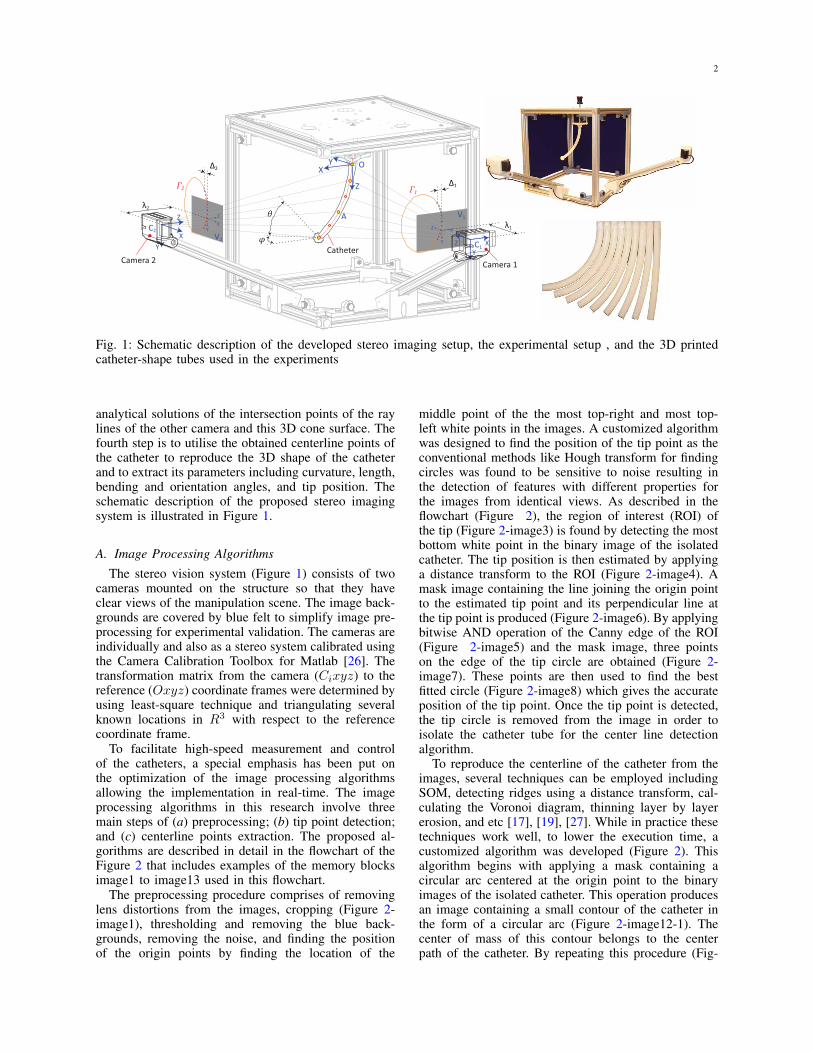
Fig. 1: Schematic description of the developed stereo imaging setup, the experimental setup , and the 3D printedcatheter-shape tubes used in the experiments
analytical solutions of the intersection points of the raylines of the other camera and this 3D cone surface. Thefourth step is to utilise the obtained centerline points ofthe catheter to reproduce the 3D shape of the catheterand to extract its parameters including curvature, length,bending and orientation angles, and tip position. Theschematic description of the proposed stereo imagingsystem is illustrated in Figure 1.
A. Image Processing Algorithms
The stereo vision system (Figure 1) consists of twocameras mounted on the structure so that they haveclear views of the manipulation scene. The image back-grounds are covered by blue felt to simplify image pre-processing for experimental validation. The cameras areindividually and also as a stereo system calibrated usingthe Camera Calibration Toolbox for Matlab [26]. Thetransformation matrix from the camera (Cixyz) to thereference (Oxyz) coordinate frames were determined byusing least-square technique and triangulating severalknown locations in R3 with respect to the referencecoordinate frame.
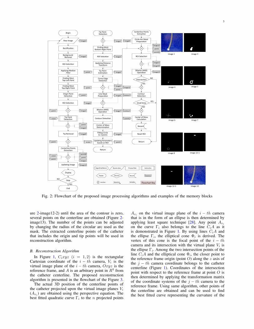
To facilitate high-speed measurement and controlof the catheters, a special emphasis has been put onthe optimization of the image processing algorithmsallowing the implementation in real-time. The imageprocessing algorithms in this research involve threemain steps of (a) preprocessing; (b) tip point detection;and (c) centerline points extraction. The proposed al-gorithms are described in detail in the flowchart of theFigure 2 that includes examples of the memory blocksimage1 to image13 used in this flowchart.
The preprocessing procedure comprises of removinglens distortions from the images, cropping (Figure 2-image1), thresholding and removing the blue back-grounds, removing the noise, and finding the positionof the origin points by finding the location of the
middle point of the the most top-right and most top-left white points in the images. A customized algorithmwas designed to find the position of the tip point as theconventional methods like Hough transform for findingcircles was found to be sensitive to noise resulting inthe detection of features with different properties forthe images from identical views. As described in theflowchart (Figure 2), the region of interest (ROI) ofthe tip (Figure 2-image3) is found by detecting the mostbottom white point in the binary image of the isolatedcatheter. The tip position is then estimated by applyinga distance transform to the ROI (Figure 2-image4). Amask image containing the line joining the origin pointto the estimated tip point and its perpendicular line atthe tip point is produced (Figure 2-image6). By applyingbitwise AND operation of the Canny edge of the ROI(Figure 2-image5) and the mask image, three pointson the edge of the tip circle are obtained (Figure 2-image7). These points are then used to find the bestfitted circle (Figure 2-image8) which gives the accurateposition of the tip point. Once the tip point is detected,the tip circle is removed from the image in order toisolate the catheter tube for the center line detectionalgorithm.
To reproduce the centerline of the catheter from theimages, several techniques can be employed includingSOM, detecting ridges using a distance transform, cal-culating the Voronoi diagram, thinning layer by layererosion, and etc [17], [19], [27]. While in practice thesetechniques work well, to lower the execution time, acustomized algorithm was developed (Figure 2). Thisalgorithm begins with applying a mask containing acircular arc centered at the origin point to the binaryimages of the isolated catheter. This operation producesan image containing a small contour of the catheter inthe form of a circular arc (Figure 2-image12-1). Thecenter of mass of this contour belongs to the centerpath of the catheter. By repeating this procedure (Fig-
3
Raw Image
Centerline PointsExtraction
Tip PointDetectionBegin
Return
Finding MostBottom-Right Point
ROI Selection
Applying DistanceTransform
Tip Point Estimation
Canny EdgeDetection
Line MaskPreparation
Bitwise (AND)Operation
Contour Detection
Center of MassDetermination
Fitting Circle to 3 points
Updating Parametersbased on ROI
Bitwise (AND)Operation
ROI Selection
Circle-Arc MaskPreparation
Intersection
Contour Detection
Small Area
Return
Record
Reset ROI
Center of MassCalculation
Rectification
Background Removal
ROI Selection
Applying MedianFilter
Finding MostTop-Left Point
Finding MostTop-Right Point
Origin PointDetection
ROI Selection
Tip PointDetection
Display
Stop
Centerline PointsExtraction
End
Tip Removal
Updating Image
YES
NO
YES
YES
NO
NO
image 1 image 3
image3
circle1
point1
image2
image6
image7
point3
image3
image8
image1
image4
image5
point2
image9
image11
image10
image10
point1
point4[]
Flowchart Key
Receive dataBegin/End/Return Process/Task
Display
Subroutine
Record
Junction Sequence Variables
Decision memory
point2 image12
image12
contour1
contour1
point4[]
image2
point1
image2
image9
point4[]
point3
image1
point3
image2
image13
point1
circle1
point1
circle1
point1
image 4 image 5
image 6 image 7
image 8 image 12-1
image 12-2 image 13
Fig. 2: Flowchart of the proposed image processing algorithms and examples of the memory blocks
ure 2-image12-2) until the area of the contour is zero,several points on the centerline are obtained (Figure 2-image13). The number of the points can be adjustedby changing the radius of the circular arc used as themask. The extracted centerline points of the catheterthat includes the origin and tip points will be used inreconstruction algorithm.
B. Reconstruction AlgorithmIn Figure 1, Cixyz (i = 1, 2) is the rectangular
Cartesian coordinate of the i − th camera, Vi is thevirtual image plane of the i − th camera, Oxyz is thereference frame, and A is an arbitrary point in R3 fromthe catheter centerline. The proposed reconstructionalgorithm is presented in the flowchart of the Figure 3.
The actual 3D position of the centerline points ofthe catheter projected upon the virtual image planes Vi(Avi ) are obtained using the perspective equation. Thebest fitted quadratic curve Γi to the n projected points
Avi on the virtual image plane of the i − th camerathat is in the form of an ellipse is then determined byapplying least square technique [28]. Any point Avion the curve Γi also belongs to the line CiA as itis demonstrated in Figure 1. By using lines CiA andthe ellipse Γi, the elliptical cone Φi is derived. Thevertex of this cone is the focal point of the i − thcamera and its intersection with the virtual plane Vi isthe ellipse Γi. Among the two intersection points of theline CiA and the elliptical cone Φi, the closer point tothe reference frame origin (point O) along the z axis ofthe j − th camera coordinate belongs to the cathetercenterline (Figure 1). Coordinates of the intersectionpoint with respect to the reference frame at point O isthen determined by applying the transformation matrixof the coordinate systems of the j − th camera to thereference frame. Using same algorithm, other points ofthe centerline are obtained and can be used to findthe best fitted curve representing the curvature of the

4
catheter in 3D space. This curve will then be used toobtain other features of the catheter including length.
i=1 , j=2
Δ1 > Δ2
i=2 , j=1
Find points A projected on Vi and Vj planes
Find upper-half points
Fit ellipse Γi
Find equation of elliptic cone Φi
Find intersections of lines CjAvi with elliptic cone Φi
Find equations of lines CjAvi
Choose right intersectionpoint sets
Fit ellipse Γ and circle
Find θ and φ
Δ1 = 0Δ2 = 0 &
Find catheter length(ellipse and circle)
Find origin and tip points using triangulation
Find catheter length
Start
Image AcquisitionCamera 1
Image AcquisitionCamera 2
Image Processing 1
Image Processing 2
Stop
Image AcquisitionThreads
Image ProcessingThreads
CalculationThread
YES NO
YESNO
Fig. 3: 3D reconstruction algorithm based on theclosed-form analytical solution of the reconstructionof quadratic curves in 3D space from two arbitraryperspective projections
Figure 4 presents the 3D plots illustrating the recon-struction algorithm for a catheter with the bending angleof 50 deg in the orientation angles of 30 deg (Figure 4-left) and 60 deg (Figure 4-right). The 3D ellipticalcones and the ray-lines of the cameras selected forthe reconstruction algorithm are demonstrated in thesefigures. As described in the reconstruction flowchart(Figure 2), amongst the two 3D elliptical cones, one ischosen based on the parameter ∆i (Figure 1). For thecatheter-shape tube positioned in the orientation angleof 30 deg (Figure 4-left), the catheter is more exposedto the first (right) camera. This makes the cone of thiscamera more suitable for the reconstruction algorithm.When the orientation angle is larger than 45 deg forthe first quadrant, the second (left) camera has betterview of the catheter-shape tube with more horizontallystretched cone (Figure 4-right). Therefore, in this casethe left camera cone is employed for the reconstructionalgorithm (Figure 4-right).
Cam 2
Cam 1
Cam 2
Cam 1
Fig. 4: 3D plots of the reconstruction cones and ray-lines for catheters with orientation angles of 30 deg(left) and 60 deg (right)
III. EXPERIMENTS
A stereo vision system consisting of two webcams(Logitech Webcam C930e; 1920×1080 pixels @ 30fps) is integrated into the experimental setup (Figure 1).In the first experiment, 3D printed catheter-shape tubes(Figure 1) with known bending angles of 10, 30, 50,and 70 deg (160 mm long and 12 mm in diameter)are manually positioned in the orientation angles of30, 60, 120, 150, 210, 240, 300, and 330 deg andthe image processing and reconstruction algorithms areperformed. In the second experiment, the tubes with thebending angles of 10, 20, 30, 40, 50, 60, and 70 degwere tested by manually rotating them in front of thecameras while the proposed shape sensing algorithmswere determining curvature and geometry of the tubes inreal-time. The measurement was repeated and recordedthree times.
Mea
nE
rror
(mm
)
10 30 50 700.00.10.20.30.40.50.6
X
10 30 50 700.00.10.20.30.40.50.6
Y
10 30 50 700.00.10.20.30.40.50.6
Z
10 30 50 700.00.10.20.30.40.50.6
3
10 30 50 700.00.10.20.30.40.50.6
?
10 30 50 700.00.10.20.30.40.50.6
L
θ (deg)
Fig. 5: Mean errors of x, y, and z coordinates of thetip point and bending angles (θ), orientation angles (φ),and length (L) measured for the tubes with the bendingangles of 10, 30, 50, and 70 deg
Figures 5 presents the mean of the measurement er-rors for x, y, and z coordinates of the tip point, bendingand orientation angles, and length of the catheter acrossthe workspace for different bending angles of 10, 30,50, and 70 deg. Figure 6 presents examples of themeasurement errors in height of the tip point, bendingangles, and length of the tube with 30 deg bending

5
angle, respectively from top to bottom. As it is clearfrom these figures, the mean of the measurement errorsfor all the parameters x, y, z, θ, φ, L are less than0.5 mm and 0.5 deg.
Err
or(m
man
dde
g)
0 45 90 135 180 225 270 315 360-0.6
0
0.6
0 45 90 135 180 225 270 315 360-0.6
0
0.6
0 45 90 135 180 225 270 315 360-0.6
0
0.6
Orientation Angle φ (deg)
Fig. 6: Sample measurement errors of z coordinate ofthe tip point, bending angle, and length of the tubewith 30 deg bending angle in the second experiment,respectively from top to bottom
The execution time required for the entire imageprocessing algorithms proposed in this research is mea-sured to be 2.75 millisecond for the two images withthe resolution of 1920×1080 pixels, and for the 3Dreconstruction algorithm is measured to be 2.25 mil-lisecond allowing the processing rate of around 200 fps.However, the web cameras used in the experimentalsetup developed in this research are limited to 30 fps.
To compare the results from the proposed algorithmwith those of the previously proposed researches, asampling of the diversity of the vision-based algo-rithms for 2D/3D reconstruction of catheters/continuumrobots/flexible manipulators is compiled in Table I.Some of the results listed in this table are promisingin terms of accuracy, however, low speed, dependencyto tip- or body-mounted fiducial markers, physical grids,or high number of required cameras/images restricttheir capabilities for high speed application like motioncompensation cardiac catheters.
IV. CONCLUSION
In this paper, a vision-based shape sensing algorithmfor real-time 3D reconstruction of cardiac cathetersusing two arbitrary perspective views based on theclosed-form analytical solution for the reconstruction ofquadratic curves in 3D space was presented. The exe-cution time of the 3D reconstruction algorithm is mea-sured to be 2.25 millisecond. The proposed algorithmcombined with a high-speed image processing algorithmsimilar to the one proposed here allows the processingrate of around 200 fps or even more. The experimentalresults demonstrated the maximum measurement errorsof 0.5 mm for the tip position and length and 0.5 degfor the bending and orientation angles of the catheter-shape rapid-prototyped tubes with known geometry andcurvature. The high-speed, accuracy, and no dependencyto body-mounted fiducial markers in the proposed sys-tem makes it a potential solution for the shape-sensingof motion compensation cardiac catheters.
TABLE I: Summary of previous studies
Author(s) Application Algorithm / Technique Camera Type # ofCamera Resolution Software Accuracy Speed
Rucker [29] Medical Body-Mounted Fiducial SonyXCD-X710 2 1024×768 Matlab 2.2
mm..
Lee [30] Medical Epipolar Reconstruction X-Ray 2 ... Matlab 2.5 - 3pixel
596.7+134 ms1.36 fps
Hannan [31] Not Medical Body-Mounted Fiducial Dalsa CCD 1 ... ... ... 1.67 ms598.8 fps
Camarillo [17], [18] Medical Shape-from-Silhouette Webcam 3 640×480 OpenCV 0.24 - 0.77mm
250-333.3 ms3-4 fps
Berthilsson [20], [32] General Affine Shape ... 6-13 ... ... 1/20pixel
...
Webster [12] Medical Tip-Mounted Fiducial SonyXCD-X710 2 ... Matlab ... 66.6 ms
15 fps
Martinsson [33] QualityControl Fixed Complexity Model ... 20 1392×1040 ... 0.157
mm...
Hong [34] General Symmetric Curves ... 1 ... Matlab ... 10 min0.001 fps
Croom [19] Medical Self-Organizing Maps SonyXCD-X710 2 1024×768 Matlab 1.53-3.14 M1
0.31-0.93 Sd2248 ms4 fps
This Research Medical Closed-Form Solution Webcam 2 1920×1080 OpenCV 0.6 Mx3
0.2 M1 & Sd22.75+2.25 ms
202 fps1Mean error in mm 2Standard deviation error in mm 3Maximum error in mm

6
REFERENCES
[1] D. Trivedi, C. D. Rahn, W. M. Kier, and I. D. Walker, “Softrobotics: Biological inspiration, state of the art, and futureresearch,” Applied Bionics and Biomechanics, vol. 5, no. 3,pp. 99–117, 2008.
[2] D. B. Camarillo, C. F. Milne, C. R. Carlson, M. R. Zinn,and J. K. Salisbury, “Mechanics modeling of tendon-drivencontinuum manipulators,” Robotics, IEEE Transactions on,vol. 24, no. 6, pp. 1262–1273, 2008.
[3] R. J. Webster, J. M. Romano, and N. J. Cowan, “Mechanicsof precurved-tube continuum robots,” Robotics, IEEE Transac-tions on, vol. 25, no. 1, pp. 67–78, 2009.
[4] K. Ikuta, T. Hasegawa, and S. Daifu, “Hyper redundant minia-ture manipulator” Hyper Finger” for remote minimally invasivesurgery in deep area,” in Robotics and Automation, 2003. Pro-ceedings. ICRA’03. IEEE International Conference on, vol. 1.IEEE, 2003, pp. 1098–1102.
[5] G. Robinson and J. B. C. Davies, “Continuum robots-a state ofthe art,” in Robotics and Automation, 1999. Proceedings. 1999IEEE International Conference on, vol. 4. IEEE, 1999, pp.2849–2854.
[6] B. A. Jones and I. D. Walker, “Kinematics for multisectioncontinuum robots,” Robotics, IEEE Transactions on, vol. 22,no. 1, pp. 43–55, 2006.
[7] V. K. Chitrakaran, A. Behal, D. M. Dawson, and I. D. Walker,“Setpoint regulation of continuum robots using a fixed camera,”in American Control Conference, 2004. Proceedings of the2004, vol. 2. IEEE, 2004, pp. 1504–1509.
[8] J. Lee, S. N. Sponberg, O. Y. Loh, A. G. Lamperski, R. J.Full, and N. J. Cowan, “Templates and anchors for antenna-based wall following in cockroaches and robots,” Robotics,IEEE Transactions on, vol. 24, no. 1, pp. 130–143, 2008.
[9] S. Leleu, H. Abou-Kandil, and Y. Bonnassieux, “Piezoelectricactuators and sensors location for active control of flexiblestructures,” Instrumentation and Measurement, IEEE Transac-tions on, vol. 50, no. 6, pp. 1577–1582, 2001.
[10] K. T. V. Grattan and T. Sun, “Fiber optic sensor technology: anoverview,” Sensors and Actuators A: Physical, vol. 82, no. 1,pp. 40–61, 2000.
[11] T. Matsuno, T. Fukuda, and F. Arai, “Flexible rope manip-ulation by dual manipulator system using vision sensor,” inAdvanced Intelligent Mechatronics, 2001. Proceedings. 2001IEEE/ASME International Conference on, vol. 2. IEEE, 2001,pp. 677–682.
[12] R. J. Webster III, J. P. Swensen, J. M. Romano, and N. J.Cowan, “Closed-form differential kinematics for concentric-tube continuum robots with application to visual servoing,” inExperimental Robotics. Springer, 2009, pp. 485–494.
[13] R. J. Webster, J. Memisevic, and A. M. Okamura, “Designconsiderations for robotic needle steering,” in Robotics andAutomation, 2005. ICRA 2005. Proceedings of the 2005 IEEEInternational Conference on. IEEE, 2005, pp. 3588–3594.
[14] V. Kallem and N. J. Cowan, “Image-guided control of flexiblebevel-tip needles,” in Robotics and Automation, 2007 IEEEInternational Conference on. IEEE, 2007, pp. 3015–3020.
[15] D. Glozman and M. Shoham, “Image-guided robotic flexibleneedle steering,” Robotics, IEEE Transactions on, vol. 23, no. 3,pp. 459–467, 2007.
[16] H.-J. Bender, R. Manner, C. Poliwoda, S. Roth, and M. Walz,“Reconstruction of 3D catheter paths from 2D X-ray projec-tions,” in Medical Image Computing and Computer-AssistedIntervention–MICCAI’99. Springer, 1999, pp. 981–989.
[17] D. B. Camarillo, K. E. Loewke, C. R. Carlson, and J. K.Salisbury, “Vision based 3-D shape sensing of flexible manip-ulators,” in Robotics and Automation, 2008. ICRA 2008. IEEEInternational Conference on. IEEE, 2008, pp. 2940–2947.
[18] D. B. Camarillo, C. R. Carlson, and J. K. Salisbury, “Con-figuration tracking for continuum manipulators with coupledtendon drive,” Robotics, IEEE Transactions on, vol. 25, no. 4,pp. 798–808, 2009.
[19] J. M. Croom, D. C. Rucker, J. M. Romano, and R. J. Webster,“Visual sensing of continuum robot shape using self-organizingmaps,” in Robotics and Automation (ICRA), 2010 IEEE Inter-national Conference on. IEEE, 2010, pp. 4591–4596.
[20] R. Berthilsson, K. Astrom, and A. Heyden, “Projective recon-struction of 3d-curves from its 2d-images using error modelsand bundle adjustments,” in Proceedings of the ScandinavianConference on Image Analysis, vol. 2. proceedings publishedby various publishers, 1997, pp. 581–588.
[21] G. Sparr, “Simultaneous reconstruction of scene structure andcamera locations from uncalibrated image sequences,” in Pat-tern Recognition, 1996., Proceedings of the 13th InternationalConference on, vol. 1. IEEE, 1996, pp. 328–333.
[22] R. L. M. E. do Rego, A. F. R. Araujo, and F. B. de Lima Neto,“Growing self-organizing maps for surface reconstruction fromunstructured point clouds,” in Neural Networks, 2007. IJCNN2007. International Joint Conference on. IEEE, 2007, pp.1900–1905.
[23] K. Kanatani and W. Liu, “3D interpretation of conics andorthogonality,” CVGIP: Image Understanding, vol. 58, no. 3,pp. 286–301, 1993.
[24] M. Xie and M. Thonnat, “A theory of 3D reconstruction ofheterogeneous edge primitives from two perspective views,” inComputer Vision—ECCV’92. Springer, 1992, pp. 715–719.
[25] R. Balasubramanian, S. Das, and K. Swaminathan, “Recon-struction of quadratic curves in 3-D from two or more per-spective views,” Mathematical problems in Engineering, vol. 8,no. 3, pp. 207–219, 2002.
[26] J.-Y. Bouguet, “Camera Calibration Toolbox for Matlab.”[Online]. Available: http://www.vision.caltech.edu/bouguetj/calib doc/index.html
[27] G. S. Kumar, P. K. Kalra, and S. G. Dhande, “Curve andsurface reconstruction from points: an approach based on self-organizing maps,” Applied Soft Computing, vol. 5, no. 1, pp.55–66, 2004.
[28] R. Halir and J. Flusser, “Numerically stable direct least squaresfitting of ellipses,” in Proc. 6th International Conference inCentral Europe on Computer Graphics and Visualization.WSCG, vol. 98. Citeseer, 1998, pp. 125–132.
[29] D. C. Rucker, “THE MECHANICS OF CONTINUUMROBOTS: MODEL–BASED SENSING AND CONTROL,”Ph.D. dissertation, Vanderbilt University, 2011.
[30] W.-S. Lee and T. Poston, “Rapid 3D tube reconstruction fromnearby views,” in Fifth International Conference in CentralEurope in Computer Graphics and Visualization. Citeseer,1997, pp. 262–271.
[31] M. W. Hannan and I. D. Walker, “Real-time shape estimationfor continuum robots using vision,” Robotica, vol. 23, no. 05,pp. 645–651, 2005.
[32] R. Berthilsson and K. Astrom, “Reconstruction of 3d-curvesfrom 2d-images using affine shape methods for curves,” inComputer Vision and Pattern Recognition, 1997. Proceedings.,1997 IEEE Computer Society Conference on. IEEE, 1997, pp.476–481.
[33] H. Martinsson, F. Gaspard, A. Bartoli, and J.-M. Lavest,“Reconstruction of 3d curves for quality control,” in ImageAnalysis. Springer, 2007, pp. 760–769.
[34] W. Hong, Y. Ma, and Y. Yu, “Reconstruction of 3-D symmetriccurves from perspective images without discrete features,” in
Computer Vision-ECCV 2004. Springer, 2004, pp. 533–545.