1-idle mode behavior
DESCRIPTION
ModeTRANSCRIPT
www.legend-technologies.org
IDLE MODE BEHAVIOR

www.legend-technologies.org
• MS in Idle Mode
– Doesn’t have a dedicated channel, but able to access the Network and able to be reached by the Network.
– MS will always try to camp on the best cell based on the signal strength criterion.
– MS will continuously monitor the serving and neighbor BCCH carriers to decide which cell to camp on.
– The purpose behind studying the Idle Mode Behavior is to always ensure that the MS is camped on the cell where it has the highest probability of successful communication.
www.legend-technologies.org
• MS Tasks during Idle Mode
– PLMN Selection.– Cell Selection.– Cell Reselection.– Location Updating.– Monitor the Incoming Paging.
www.legend-technologies.org
• MS Tasks during Idle Mode
– PLMN Selection– Cell Selection.– Cell Reselection.– Location Updating.– Monitor the Incoming Paging.

www.legend-technologies.org
• PLMN Selection Criterion– PLMN identity is defined as “MCC+MNC” which is part of the LAI, where
LAI=MCC+MNC+LAC. MCC: Mobile Country Code - MNC: Mobile Network Code - LAC: Location Area Code
– When the MS is powered ON, it will perform a Location Update and compare the new LAI with the old stored one.
– An MS will need to make a PLMN selection only incase:1. MS is powered ON for the 1st time i.e. No PLMN was registered on before (No Information on MCC&MNC is stored on SIM)2. Old PLMN is not available any more.

www.legend-technologies.org
• PLMN Selection Criterion– When the MS has to do a PLMN selection due to one of the previous cases, the
selection mode will depend on the MS settings either Automatic or Manual.– Automatic PLMN Selection Mode steps:1. Home PLMN.2. Each PLMN stored on the SIM card in priority order.3. Other PLMNs have Signal Strength > -85 dBm in random order.4. All other PLMNs in order of decreasing Signal Strength.
– Manual PLMN Selection Mode:1. Home PLMN.2. All other available PLMNs and give the user the choice to select.

www.legend-technologies.org
• PLMN Selection Criterion National Roaming
– If National Roaming is permitted then a MS can register on a PLMN in its home country other than its home PLMN.
– National Roaming may be allowed on a certain location areas LAs of the visitor PLMN.
– MS should periodically try to access back his home PLMN, but this periodic attempts will occur only on Automatic selection mode.
www.legend-technologies.org
• MS Tasks during Idle Mode
– PLMN Selection.– Cell Selection– Cell Reselection.– Location Updating.– Monitor the Incoming Paging.

www.legend-technologies.org
• Cell Selection Criterion
– The Cell Selection algorithm tries to find the most suitable cell in the selected PLMN and make the MS camp on.
– Cell Selection is done by the MS itself.
– During Idle Mode the Network doesn’t know the cell which the MS is camping on, it only knows the Location Area where the mobile registed himself in.

www.legend-technologies.org
• Cell Selection Criterion
MS will synchronize to the BCCH frequency and read system information (LAI,BA List,…etc)
Scan RF Frequencies one by one and calculates the Average received signal strength over 3 5 seconds
Tune to the RF Frequency with the highest average received signal strength
Camp on the Cell
Check if the chosen frequency is a BCCH carrier frequency or not
Check if C1 > 0 or not
Check if Cell is barred or not
Check if PLMN is desired or not
Tune to the next higher frequency that wasn’t tried before
Yes
Yes
Yes
Yes
No
No
No
No
www.legend-technologies.org
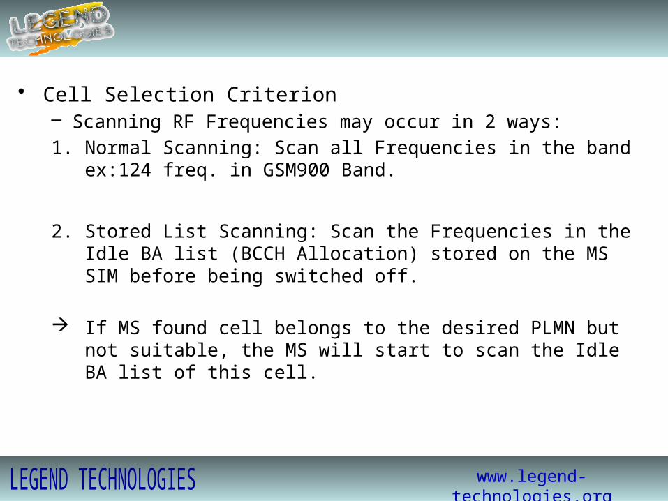
• Cell Selection Criterion– Scanning RF Frequencies may occur in 2 ways:1. Normal Scanning: Scan all Frequencies in the band ex:124 freq. in GSM900 Band.
2. Stored List Scanning: Scan the Frequencies in the Idle BA list (BCCH Allocation) stored on the MS SIM before being switched off.
If MS found cell belongs to the desired PLMN but not suitable, the MS will start to scan the Idle BA list of this cell.
www.legend-technologies.org
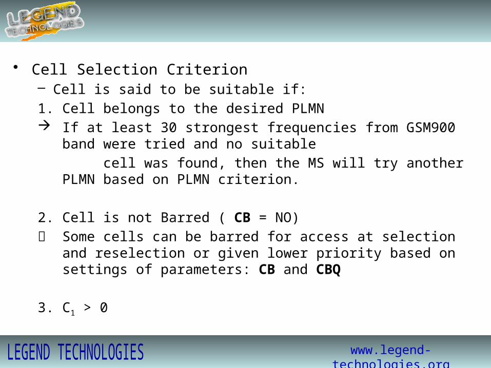
• Cell Selection Criterion– Cell is said to be suitable if:1. Cell belongs to the desired PLMN If at least 30 strongest frequencies from GSM900 band were tried and no suitable cell was found, then the MS will try another PLMN based on PLMN criterion. 2. Cell is not Barred ( CB = NO) Some cells can be barred for access at selection and reselection or given lower
priority based on settings of parameters: CB and CBQ
3. C1 > 0

www.legend-technologies.org
• Cell Selection Criterion– C1 is called “Cell Selection Quantity”– It is calculated at the MS based on the below equation:C1 = (Received SS – ACCMIN) – max (CCHPWR-P,0)
ACCMIN Minimum allowed DL received SS at the MS in order to access the systemCCHPWR Maximum allowed transmitting power by the MS in the UL.P Maximum out put power of the MS according to its class.
N.B: 1. ACCMIN and CCHPWR are cell parameters sent to the MS at the BCCH channel.2. If CCHPWR > P then C1 will decrease and so the Received SS should be large
enough to keep C1 > 0 (May be this cell is not designed of this MS class)
3. C1, ACCMIN, CCHPWR, P are all measured in dBm.
www.legend-technologies.org
• MS Tasks during Idle Mode
– PLMN Selection.– Cell Selection.– Cell Reselection– Location Updating.– Monitor the Incoming Paging.
www.legend-technologies.org
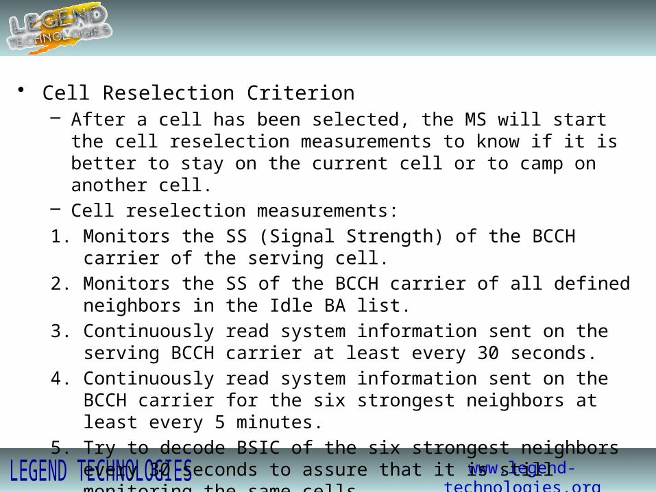
• Cell Reselection Criterion– After a cell has been selected, the MS will start the cell reselection measurements to
know if it is better to stay on the current cell or to camp on another cell.– Cell reselection measurements:1. Monitors the SS (Signal Strength) of the BCCH carrier of the serving cell.2. Monitors the SS of the BCCH carrier of all defined neighbors in the Idle BA list.3. Continuously read system information sent on the serving BCCH carrier at least
every 30 seconds.4. Continuously read system information sent on the BCCH carrier for the six
strongest neighbors at least every 5 minutes.5. Try to decode BSIC of the six strongest neighbors every 30 seconds to assure that
it is still monitoring the same cells.
www.legend-technologies.org
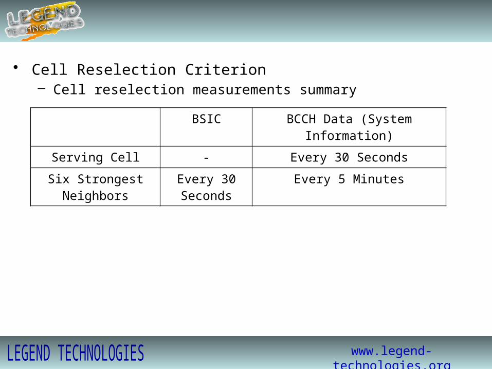
• Cell Reselection Criterion– Cell reselection measurements summary BSIC BCCH Data (System Information)
Serving Cell - Every 30 Seconds
Six Strongest Neighbors Every 30 Seconds Every 5 Minutes

www.legend-technologies.org
• Cell Reselection Criterion– When Cell Reselection will occur ?
1. Serving Cell became barred ( CB = YES )
2. C1 serving cell falls below zero for more than 5 seconds.
3. MS tried to access the network through this cell unsuccessfully for the allowed no. of times defined by the parameter MAXRET
4. C2 neighbor cell ( one of the six strongest neighbors) became greater than C2 serving cell for more than 5 seconds.
5. MS detects Downlink Signaling Failure.
www.legend-technologies.org
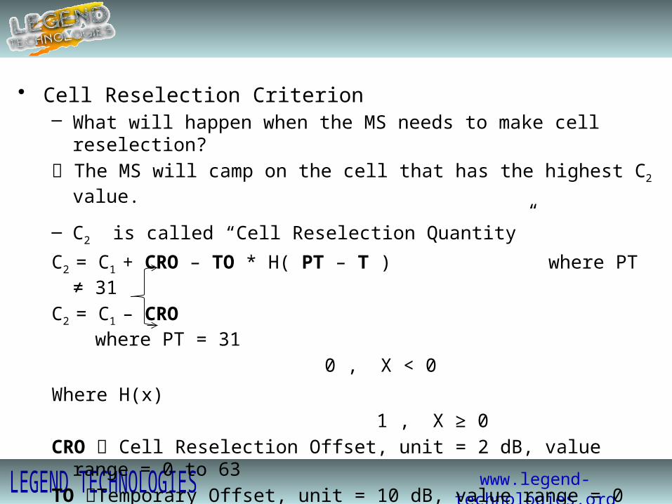
• Cell Reselection Criterion– What will happen when the MS needs to make cell reselection? The MS will camp on the cell that has the highest C2 value.
– C2 is called “Cell Reselection Quantity”
C2 = C1 + CRO – TO * H( PT – T ) where PT ≠ 31
C2 = C1 – CRO where PT = 31
0 , X < 0
Where H(x) 1 , X ≥ 0CRO Cell Reselection Offset, unit = 2 dB, value range = 0 to 63TO Temporary Offset, unit = 10 dB, value range = 0 to 7PT Penalty Time during which TO is validT Initiated from zero when the MS places the neighbor in the list of the Six Strongest
www.legend-technologies.org
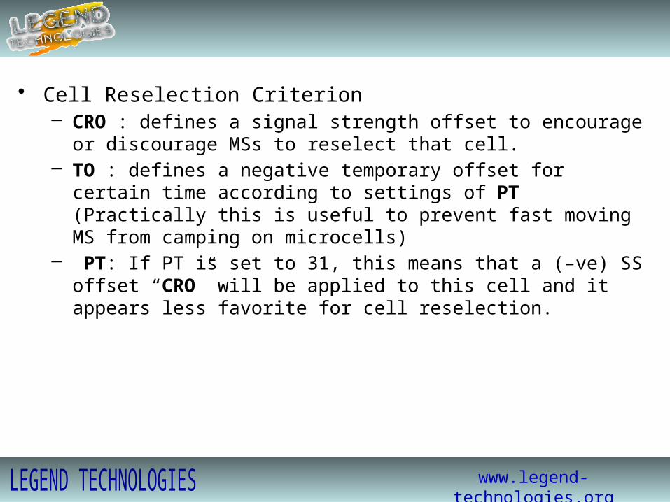
• Cell Reselection Criterion– CRO : defines a signal strength offset to encourage or discourage MSs to reselect
that cell.– TO : defines a negative temporary offset for certain time according to settings of PT
(Practically this is useful to prevent fast moving MS from camping on microcells)– PT: If PT is set to 31, this means that a (–ve) SS offset “CRO” will be applied to this
cell and it appears less favorite for cell reselection.

www.legend-technologies.org
• Cell Reselection Criterion Down Link Signaling Failure Algorithm– The Algorithm of type “Leaky Bucket” and used a counter “D”, where D = 90/MFRMS– MFRMS is a parameter defines the no. of multiframes between the transmission of
each paging group i.e. if MFRMS=4 then a MS attached to a certain paging group will wait in sleeping mode for 4 multiframes (4*253msec) until it is up again to listen to paging.
– When the MS is up to listen to its paging group, if the message is not decoded successfully then D is decremented by 4 and if the message is decoded correctly then D is incremented by 1.
– If D reaches zero, then a Down Link Signaling Failure is detected and cell reselection took place.

www.legend-technologies.org
• Cell Reselection Criterion Down Link Signaling Failure Algorithm– Ex: Assume that MFRMS = 4
Downlink signaling failure counter is initialized: D = round(90/MFRMS)=22.If the MS successfully decodes a paging message, then: D = D + 1 = 23.If the MS unsuccessfully decodes a paging message, then: D = D - 4 = 18.
If D reaches zero, then a Down Link Signaling Failure is detected and cell reselection took place.
www.legend-technologies.org
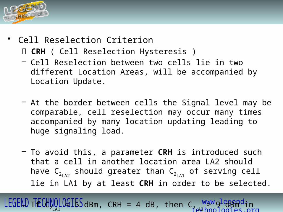
• Cell Reselection Criterion CRH ( Cell Reselection Hysteresis )– Cell Reselection between two cells lie in two different Location Areas, will be
accompanied by Location Update.
– At the border between cells the Signal level may be comparable, cell reselection may occur many times accompanied by many location updating leading to huge signaling load.
– To avoid this, a parameter CRH is introduced such that a cell in another location area LA2 should have C2LA2
should greater than C2LA1 of serving cell lie in LA1 by at least
CRH in order to be selected.
– If C2LA1 = 5 dBm, CRH = 4 dB, then C2LA2
≥ 9 dBm in order to be selected.

www.legend-technologies.org
• MS Tasks during Idle Mode
– PLMN Selection.– Cell Selection.– Cell Reselection.– Location Updating– Monitor the Incoming Paging.

www.legend-technologies.org
• Location Updating– To make it possible for the mobile subscriber to receive a call and initiate a call
whenever needed, the network must know where the MS is located whenever it moves that’s why Location Updating is needed.
– In the Idle Mode, the Network knows the location of the MS on a Location area resolution not on a cell resolution.
– There are three different types of location updating defined:1. Normal Location Updating.2. Periodic registration.3. IMSI attach & IMSI detach (when the MS informs the network when it enters an
inactive state)

www.legend-technologies.org
• Location Updating
1. Normal Location Updating
– Initiated by the MS when it enters a cell belongs to a new Location Area (LA).– The MS will compare the LAIold stored on the SIM with the LAInew broadcasted from
the new cell and it will found them different so it’ll perform Location Update type normal.

www.legend-technologies.org
• Location Updating
2. Periodic Registration
– Regularly the MS should update the Network with its current location Area.– The Network will inform the MS how often it should report the location Area he is
registering himself in.– Based on the value of the Parameter T3212 the MS will know how frequent it
should make periodic registration.– T3212 take values from 1 (6min) to 255 (25.5 Hours), default = 40 (4 Hours)– MSC has a supervision time = BTDM+GTDM if it doesn’t hear from the MS during
this period, the MSC will consider the MS implicitly detached.– BTDM+GTDM should > T3212 , to not consider the MS detach before periodic
location update is performed.

www.legend-technologies.org
• Location Updating
3. IMSI Attach/Detach
– IMSI attach/detach operation is an action taken by the MS to inform the Network either it will go to inactive state (Power off) or it returned back to idle mode.
– ATT is a cell parameter that will inform the MS whether IMSI attach/detach is operational or not.
– If ATT=Yes, then before the MS will be switched off, it will send an IMSI detach request to the Network, so no paging messages will be sent to this MS while it is in this state.
– When the MS is switched on again it will send an IMSI attach request to the Network so now paging messages can be sent normally to this MS.

www.legend-technologies.org
• MS Tasks during Idle Mode
– PLMN Selection.– Cell Selection.– Cell Reselection.– Location Updating.– Monitor the Incoming Paging

www.legend-technologies.org
• Monitor the Incoming Paging Let us revise the DL logical channels and their mapping:I) BCH(Broadcast Channels): including FCCH(Frequency Correction Channel)
SCH(Synchronization Channel) Always Mapped on TS0/C0BCCH(Broadcast Control Channel)
II) CCCH(Common Control Channels): including PCH(Paging Channel) Always Mapped on TS0/C0
AGCH(Access Grant Channel)III) DCCH(Dedicated Control Channels): including SDCCH(Stand Alone Dedicated Control Channel) May be Mapped on either
SACCH(Slow Associated Control Channel) TS1/C0 or TS0/C0CBCH(Cell Broadcast Channel)
FACH(Fast Associated Control Channel) “ Work in Stealing mode by
replacing the TCH time slot”

www.legend-technologies.org
CBBBBSF
2 4 6 8 10 12 14 16 18 20 22 24 26 28 30 32 34 36 38 40 42 44 46 48 50
F S F S F S F S F S I
1 3 5 7 9 11 13 15 17 19 21 23 25 27 29 31 33 35 37 39 41 43 45 47 49 51
0 1 2 3 4 5 6 7 0 1 2 3 4 5 6 7 0 1 2 3 4 5 6 7 0 1 2 3 4 5 6 7 0 1 2 3 4 5 6 7 0 1 2 3 4 5 6 7 0 1 2 3 4 5 6 7
Frame 1 Frame 2 Frame 3 Frame 4 Frame 5 Frame 6 Frame 7
Default Mapping on TS0/C0 (BCH+CCCH) “Non Combined Mode”51 TDMA Frames = 1 Control Multi-frame
B C C C C C C C C C

www.legend-technologies.org
D1D1D1D0D0D0D0
2 4 6 8 10 12 14 16 18 20 22 24 26 28 30 32 34 36 38 40 42 44 46 48 50
I I I
1 3 5 7 9 11 13 15 17 19 21 23 25 27 29 31 33 35 37 39 41 43 45 47 49 51
D0 D1 D2 D3 D4 D5 D6 D7 A0 A1 A2 A3
Frame 1 Frame 2 Frame 3 Frame 4 Frame 5 Frame 6 Frame 7
0 1 2 3 4 5 6 7 0 1 2 3 4 5 6 7 0 1 2 3 4 5 6 7 0 1 2 3 4 5 6 7 0 1 2 3 4 5 6 7 0 1 2 3 4 5 6 7 0 1 2 3 4 5 6 7
Default Mapping on TS1/C0 (SDCCH+SACCH+CBCH(optional))

www.legend-technologies.org
• Monitor the Incoming Paging Combination of Control channels (Different Mapping Criteria)
− Mapping on TS0/C0 is controlled by Parameter called BCCHTYPE
− BCCHTYPE = NCOMB (Non Combined, BCH&CCCH)TS1/C0 will carry SDCCH+SACCH
= COMB (Combined, BCH&CCCH&SDCCH/4) TS1/C0 will be free for TCH
= COMBC (Combined with cell broadcast channel CBCH is in use, BCH&CCCH&SDCCH/4&CBCH) TS1/C0 will be free for TCH
www.legend-technologies.org
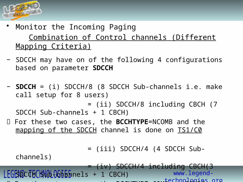
• Monitor the Incoming Paging Combination of Control channels (Different Mapping Criteria)
− SDCCH may have on of the following 4 configurations based on parameter SDCCH
− SDCCH = (i) SDCCH/8 (8 SDCCH Sub-channels i.e. make call setup for 8 users) = (ii) SDCCH/8 including CBCH (7 SDCCH Sub-channels + 1 CBCH) For these two cases, the BCCHTYPE=NCOMB and the mapping of the SDCCH channel is
done on TS1/C0
= (iii) SDCCH/4 (4 SDCCH Sub-channels) = (iv) SDCCH/4 including CBCH(3 SDCCH Sub-channels + 1 CBCH) For these two cases, the BCCHTYPE=COMB or COMBC and the mapping of the SDCCH
channel is done on TS0/C0
www.legend-technologies.org
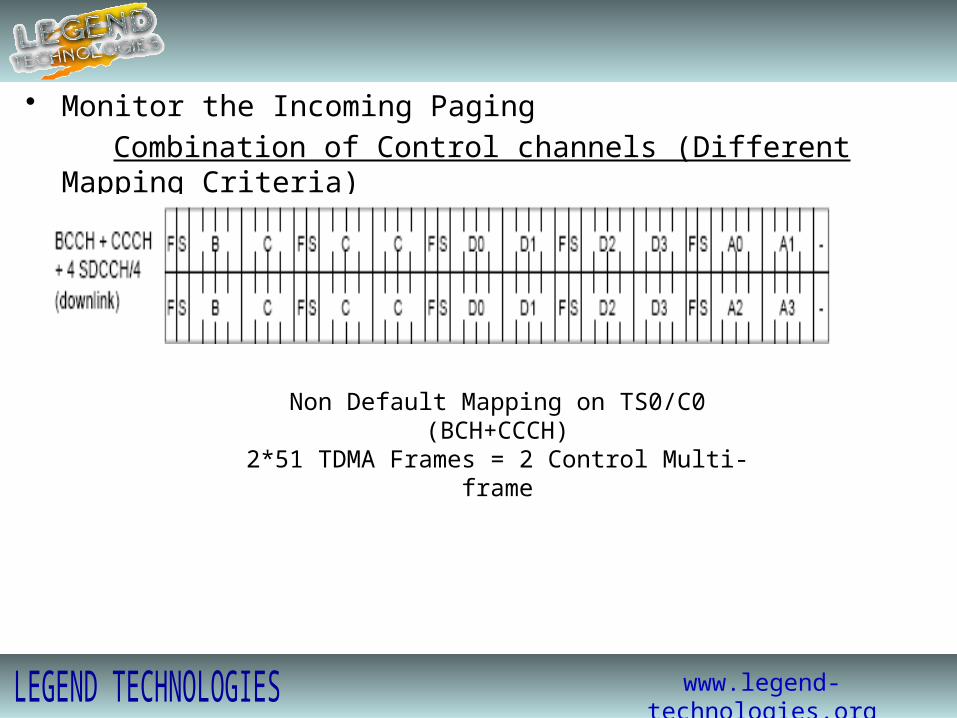
• Monitor the Incoming Paging Combination of Control channels (Different Mapping Criteria)
Non Default Mapping on TS0/C0 (BCH+CCCH)2*51 TDMA Frames = 2 Control Multi-frame

www.legend-technologies.org
• Monitor the Incoming PagingCombination of Control channels (Different Mapping Criteria)
The Table below summarizes all the previous details
Default Mapping (Non Combined) Non Default Mapping (Combined)
BCH+CCCH on TS0/C0 and SDCCH+SACCH+CBCH on TS1/C0 BCH+CCCH+SDCCH+SACCH+CBCH on TS0/C0
CBCH doesn't exist CBCH exist CBCH doesn't exist CBCH exist
1 block for BCCH 1 block for BCCH 1 block for BCCH 1 block for BCCH
9 blocks for CCCH 9 blocks for CCCH 3 blocks for CCCH 3 blocks for CCCH
8 blocks for SDDCH 7 blocks for SDDCH 4 blocks for SDDCH 3 blocks for SDDCH
1 block for CBCH 1 block for CBCH

www.legend-technologies.org
• Monitor the Incoming PagingPaging Groups
− The MS will monitor the incoming paging in only specific times, and the rest of the time it will remain in sleeping mode.
− In this way we save the MS battery and we decrease the UL interference on the system.− The MS will monitor the incoming paging when the “Paging Group” assigned for this MS is
transmitted only.− The CCCH block can be used by either PCH or AGCH.− When the CCCH block is used for paging it will be called “Paging Block”− The Paging Block consists of 4 consecutive Time slots lie in 4 consecutive frames.− The Paging Block can be used to page 4/3/2 users according to IMSI or TMSI is used
when paging the MS ( Length IMSI = 2 TS, Length TMSI = 1 TS) − The group of users belong to the same paging block will be called “Paging Group”

www.legend-technologies.org
CBBBBSF
2 4 6 8 10 12 14 16 18 20 22 24 26 28 30 32 34 36 38 40 42 44 46 48 50
F S F S F S F S F S I
1 3 5 7 9 11 13 15 17 19 21 23 25 27 29 31 33 35 37 39 41 43 45 47 49 51
0 1 2 3 4 5 6 7 0 1 2 3 4 5 6 7 0 1 2 3 4 5 6 7 0 1 2 3 4 5 6 7 0 1 2 3 4 5 6 7 0 1 2 3 4 5 6 7 0 1 2 3 4 5 6 7
Frame 1 Frame 2 Frame 3 Frame 4 Frame 5 Frame 6 Frame 7
Default Mapping on TS0/C0 (BCH+CCCH) “Non Combined Mode”51 TDMA Frames = 1 Control Multi-frame
B C C C C C C C C C

www.legend-technologies.org
• Monitor the Incoming PagingPaging Groups
− As appeared the MS will listen to paging in only specific times.− The MS will utilize the time between the 4 TS that lie in 4 consecutive frames to make the
required measurements on the neighbor cells.

www.legend-technologies.org
• Monitor the Incoming PagingPaging Groups
− As we said before the no. of the CCCH blocks will depend on either non-combined mode or combined mode is in use.
Default Mapping(Non Combined) Non Default Mapping(Combined)
BCH+CCCH on TS0/C0 and SDCCH+SACCH+CBCH on TS1/C0 BCH+CCCH+SDCCH+SACCH+CBCH on TS0/C0
CBCH doesn't exist CBCH exist CBCH doesn't exist CBCH exist
9 blocks for CCCH 9 blocks for CCCH 3 blocks for CCCH 3 blocks for CCCH
− The structure of the CCCH will depend on a parameter Called AGBLK.− If AGBLK=1 1 CCCH block will be reserved for AGCH and we will have either 8 or 2 blocks assigned for Paging. AGBLK=0 No Blocks are reserved for AGCH and we will have either 9 or 3 blocks assigned for Paging.

www.legend-technologies.org
• Monitor the Incoming PagingPaging Groups
− How many Paging Groups we have? This will depend on a parameter MFRMS− MFRMS is a parameter defined per cell and it defines how frequent the paging group
assigned for certain MS will be transmitted.− MFRMS takes values from 1 to 9, if MFRMS=1 then the paging group assigned for certain MS will be transmitted every 1
control Multiframes=253 msec if MFRMS=9 then the paging group assigned for certain MS will be transmitted every 9
control Multiframes = 9*253msec=2.3 seconds.− If MFRMS is large:Positive Side: The MS battery life time will increase coz the MS remains in sleeping mode for
long time.Negative Side: Call setup time will increase coz may be paging come to the MS while it is still
in the sleeping mode.

www.legend-technologies.org
• Monitor the Incoming PagingPaging Strategies
− Paging Strategies are controlled by parameters in the MSC.
− Setting of parameters will decide whether the paging will be local paging (within the LA) or global paging (within the MSC service area).
− Setting of parameters will decide also whether paging will be done via IMSI or TMSI.
− Using the parameters we can decide also how the second paging will be incase the first paging failed, ex: If 1st paging was local with TMSI then we can set the 2nd paging to be global with IMSI.

www.legend-technologies.org
• Related Feature to the Idle Mode BehaviorAdaptive Configuration of Logical Channels (ACLC)
− As we know the SDCCH channel is used for signaling i.e. call setup, while the TCH channel is used to carry real user traffic (speech/data).
− As a rule of thumb GOS for TCH=2% i.e. within 100 calls if 2 of them are blocked then this will be acceptable, for the SDCCH/8 the GOS=0.5% and for the SDCCH/4 the GOS=1%
− As we know in the default settings for frequency C0, TS0 is used to carry BCH+CCCH and TS1 used to carry SDCCH+SACCH, and TS2TS7 used to carry speech/data

www.legend-technologies.org
• Related Feature to the Idle Mode BehaviorAdaptive Configuration of Logical Channels (ACLC)
− Now if the signaling load is high i.e. many users need to make call setup then high blocking will occur exceeding the allowed value 0.5%
− To solve the blocking we have 2 ways:i) Static configuration of a TCH TS to be used as SDCCH forever( Now TS1&TS2 used for SDDCH+SACCH and TS3TS7 used to carry speech/data) But in this case we lost 1 TCH channel i.e. 5 users can talk simultaneously instead of 6
ii) Adaptive configuration of a TCH TS to be used as SDCCH/8 when there is blocking only( Now TS1&TS2 used for SDDCH+SACCH and TS3TS7 used to carry speech/data, butWhen there is no blocking TS2 will be configured back automatically as a TCH and used tocarry speech/data)
www.legend-technologies.org
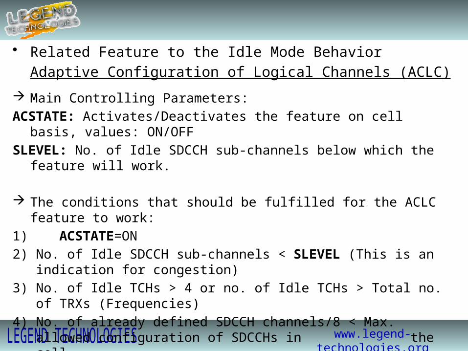
• Related Feature to the Idle Mode BehaviorAdaptive Configuration of Logical Channels (ACLC)
Main Controlling Parameters:ACSTATE: Activates/Deactivates the feature on cell basis, values: ON/OFFSLEVEL: No. of Idle SDCCH sub-channels below which the feature will work.
The conditions that should be fulfilled for the ACLC feature to work:1) ACSTATE=ON2) No. of Idle SDCCH sub-channels < SLEVEL (This is an indication for congestion)3) No. of Idle TCHs > 4 or no. of Idle TCHs > Total no. of TRXs (Frequencies)4) No. of already defined SDCCH channels/8 < Max. allowed configuration of SDCCHs in
the cell.
www.legend-technologies.org
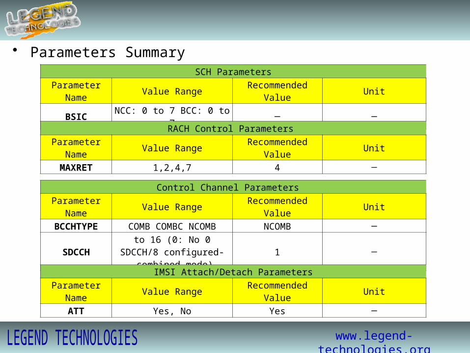
• Parameters SummarySCH Parameters
Parameter Name Value Range Recommended Value UnitBSIC NCC: 0 to 7 BCC: 0 to 7 ─ ─
RACH Control ParametersParameter Name Value Range Recommended Value Unit
MAXRET 1,2,4,7 4 ─
Control Channel ParametersParameter Name Value Range Recommended Value Unit
BCCHTYPE COMB COMBC NCOMB NCOMB ─
SDCCH 0 to 16 (0: No SDCCH/8 configured-combined mode)
1 ─
IMSI Attach/Detach ParametersParameter Name Value Range Recommended Value Unit
ATT Yes, No Yes ─
www.legend-technologies.org
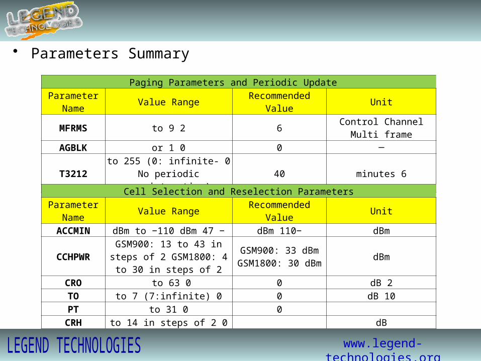
• Parameters Summary
Paging Parameters and Periodic UpdateParameter
Name Value Range Recommended Value Unit
MFRMS 2 to 9 6 Control Channel Multi frame
AGBLK 0 or 1 0 ─
T3212 0 to 255 (0: infinite-No periodic registeration)
40 6 minutes
Cell Selection and Reselection ParametersParameter
Name Value Range Recommended Value Unit
ACCMIN −47 dBm to −110 dBm −110 dBm dBm
CCHPWR GSM900: 13 to 43 in steps of 2 GSM1800: 4 to 30 in steps of 2
GSM900: 33 dBm GSM1800: 30 dBm dBm
CRO 0 to 63 0 2 dBTO 0 to 7 (7:infinite) 0 10 dBPT 0 to 31 0
CRH 0 to 14 in steps of 2 dB

www.legend-technologies.org
Thank You