1 image encryption by pixel property separation image encryption by pixel property separation...
TRANSCRIPT

1
Image Encryption by Pixel Property SeparationKarthik Chandrashekar Iyer and Aravinda Subramanya
Abstract— Pixels in an image are essentially constituted of two properties, position and colour. Pixel Property Separation, a radically differentapproach for Symmetric-key image encryption, separates these properties to disturb the semantics of the image. The scheme operates in twoorthogonal stages each requiring an encryption key. The first stage creates the Position Vector, an ordered set of Pixel Position Information controlledby a set of plaintext dependent Random Permutations. A bitmap flagging the presence of all the 24 bit colours is generated. The second stagerandomly positions the image width and height within the ciphertext and finally applies a byte transposition on the ciphertext bytes. The complete setof image properties including width, height and pixel position-colour correlation are obscured, resulting in a practically unbreakable encryption. Theorthogonality of the stages acts as an anti-catalyst for cryptanalysis. The information retrieved from compromising a stage is totally independent andcannot be used to derive the other. Classical cryptanalytic techniques demand huge number of attempts, most failing to generate valid encryptioninformation. Plaintext attacks are rendered ineffective due to the dependency of the Random Permutations on the plaintext. Linear and Differentialcryptanalysis are highly inefficient due to high Diffusion and Confusion. Although the paper describes the algorithm as applied to images, itsapplicability is not limited to images only. The cryptographic strength is independent of the nature of the plaintext.
Index Terms— Pixel Property Separation, Image Encryption, Cryptanalytic Error Avalanche Effect, random colour permutation, security,cryptography, pixel position, pixel colour, plaintext attack, confusion, diffusion.
1 INTRODUCTION
IMAGE and data security is a major challenge in Storage and Transmission applications. Encryptionalgorithms for these applications are exposed to various threats and security breaches due to the
availability of immensely powerful and inexpensive computational resources. Brute Force and Statisticalattacks on the existing cryptographic algorithms is not only possible, but are becoming more practical inthe wake of technological advancements like Distributed and Grid Computing. Vast amounts of data canbe processed in parallel by agents distributed over the Internet and aid in revealing secure information.
Several data encryption algorithms like DES [1], AES[1], IDEA[1] are being employed for protectingdigital information, chaos based [5][17], combinatorial permutation [13] and optical techniques [12] are alsoproposed for encrypting images. Along with these developments in the security domain, the vulnerabilityof the algorithms are also being exposed. It is possible to build a machine that can determine the keyused for DES encryption at a cost as low as US $10000 [16]. It is also vulnerable to Linear and Differentialcryptanalysis or a combination of both. Techniques like the Side Channel Attack and several Cache TimingAttacks have been developed to compromise AES algorithm and retrieve the encryption key in as less as65ms with 800 write operations [6]. Chaos based techniques like the CKBA are prone to plaintext attacks[7] and algorithms using combinatorial permutations are as strong as the permutation of the least sizedblock even if they apply multiple permutations over different sized image blocks.
Applications in the Automobile, Medical, Construction and the Fashion industry require designs,scanned data, building plans and blue-prints to be safe-guarded against espionage. Considering thelong lifetime of images in the mentioned domains, it is imperative to develop and employ techniqueswhich protect the content throughout their lifetime.
A novel image encryption technique based on Pixel Property Separation is proposed in this paper. Thepixel position and the colour are separated and encoded using a set of Random Permutations. Thealgorithm conceals the image colour-position correlation, the colour information and the image size.The concealment of the image size considerably enhances the cryptanalytic complexity. The Ciphertextonly attack is practically impossible while the plaintext and the differential attacks fail to reveal usefulencryption information. The algorithm is robust against Plaintext attacks due to the utilization of Plain-text Dependent Random Permutations ([18],[19]) to separate pixel properties. The time required for asuccessful Brute Force Attack is huge attributing to the high key lengths and orthogonality of encryptionstages. Hence it is not likely to be broken by brute force methods using any existing technology.
• K. C. Iyer and A. Subramanya are with the DSP Software Centre, Innovation Center, Business Unit Home, NXP Semiconductors (formerly PhilipsSemiconductors), Bangalore - 560 045, India.E-mail: [email protected], [email protected]@nxp.com, [email protected]
2
The organization of the paper is as follows. Section 2 describes Pixel Property Separation, section 3explicates and illustrates the encryption scheme. Section 4 and 5 discuss in detail the various cryptanalyticattacks and the encryption strength. The last section presents the simulation results. A mathematicalmodel for the encryption algorithm has been presented in the appendix.
2 PIXEL PROPERTY SEPARATION
Pixels in an image are essentially constituted of two properties, pixel position and pixel colour. The pixelposition is defined by the (x, y) co-ordinates indicating the horizontal and vertical distance of the pixelfrom (0, 0) and the colour value can be a RGB colour or a greyscale value. Pixel Property Separation is anencoding technique that separates the pixel position and colour and represents them as distinct vectors.The separation process results in two ordered vectors, the Position Vector Pos representing the pixelpositions and the Colour Bitmap Vector CBM that represents the colours. The vectors are defined asfollows.
1) The Position Vector Pos is an ordered set of pixel co-ordinate positions. This vector bears a positionentry for each pixel in the input image. For each (x, y) position entry, the Pos vector also indicatesby a flag flg whether an entry is the last entry for that colour. A flag value of 1 indicates that theentry is the last for that colour, a value of 0, otherwise.
2) The Colour Bitmap CBM is an ordered set of bits(flags) that indicate the presence of a colour Cin the input image. The number of bits in CBM is equal to the number of colours in the coloursystem used by the image. For example, if the image uses a 24 bit RGB colour system, then theCBM would be composed of 224 flags indicating the presence of the 224 RGB values. A flag valueof 1 indicates the presence of a colour and a value 0, otherwise.
These two vectors in combination, completely represent the image. The following illustration describesthe technique.
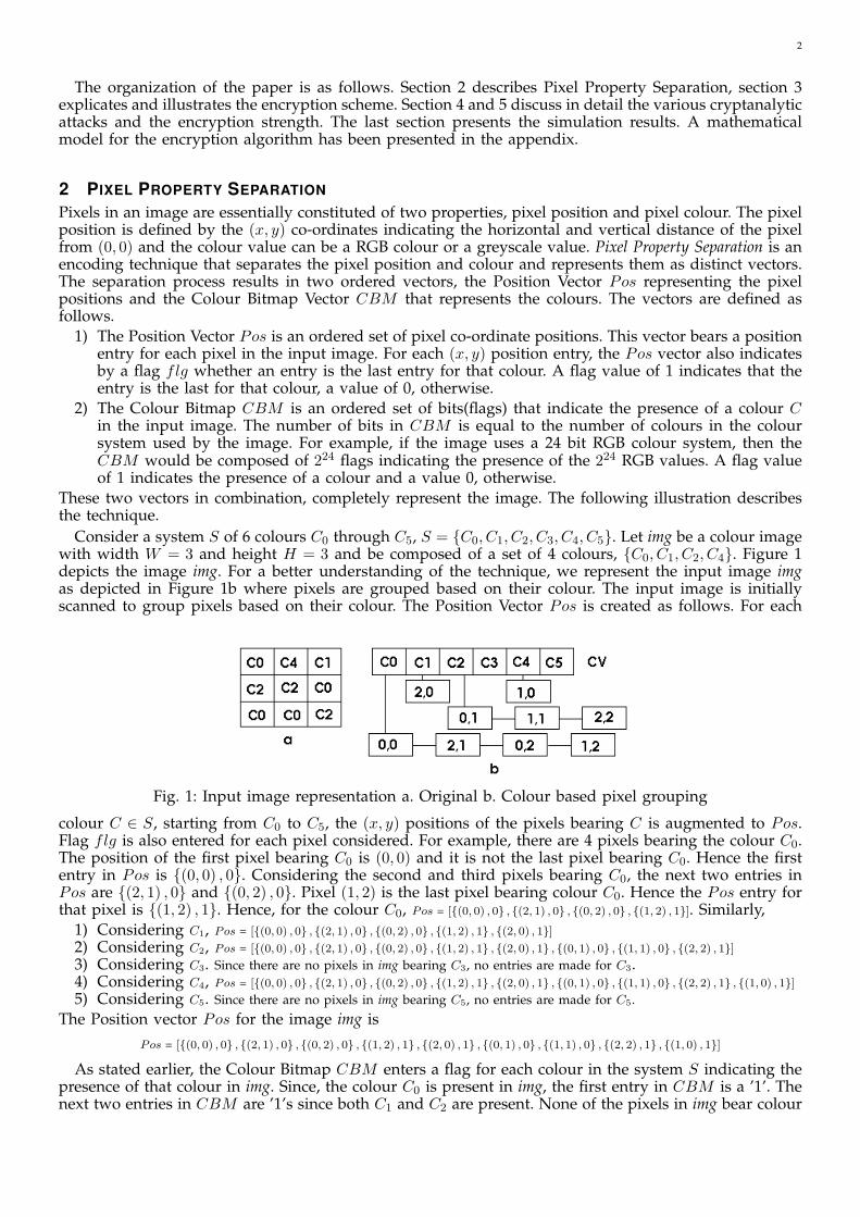
Consider a system S of 6 colours C0 through C5, S = {C0, C1, C2, C3, C4, C5}. Let img be a colour imagewith width W = 3 and height H = 3 and be composed of a set of 4 colours, {C0, C1, C2, C4}. Figure 1depicts the image img. For a better understanding of the technique, we represent the input image imgas depicted in Figure 1b where pixels are grouped based on their colour. The input image is initiallyscanned to group pixels based on their colour. The Position Vector Pos is created as follows. For each
Fig. 1: Input image representation a. Original b. Colour based pixel grouping
colour C ∈ S, starting from C0 to C5, the (x, y) positions of the pixels bearing C is augmented to Pos.Flag flg is also entered for each pixel considered. For example, there are 4 pixels bearing the colour C0.The position of the first pixel bearing C0 is (0, 0) and it is not the last pixel bearing C0. Hence the firstentry in Pos is {(0, 0) , 0}. Considering the second and third pixels bearing C0, the next two entries inPos are {(2, 1) , 0} and {(0, 2) , 0}. Pixel (1, 2) is the last pixel bearing colour C0. Hence the Pos entry forthat pixel is {(1, 2) , 1}. Hence, for the colour C0, Pos = [{(0, 0) , 0} , {(2, 1) , 0} , {(0, 2) , 0} , {(1, 2) , 1}]. Similarly,
1) Considering C1, Pos = [{(0, 0) , 0} , {(2, 1) , 0} , {(0, 2) , 0} , {(1, 2) , 1} , {(2, 0) , 1}]2) Considering C2, Pos = [{(0, 0) , 0} , {(2, 1) , 0} , {(0, 2) , 0} , {(1, 2) , 1} , {(2, 0) , 1} , {(0, 1) , 0} , {(1, 1) , 0} , {(2, 2) , 1}]3) Considering C3. Since there are no pixels in img bearing C3, no entries are made for C3.4) Considering C4, Pos = [{(0, 0) , 0} , {(2, 1) , 0} , {(0, 2) , 0} , {(1, 2) , 1} , {(2, 0) , 1} , {(0, 1) , 0} , {(1, 1) , 0} , {(2, 2) , 1} , {(1, 0) , 1}]5) Considering C5. Since there are no pixels in img bearing C5, no entries are made for C5.
The Position vector Pos for the image img isPos = [{(0, 0) , 0} , {(2, 1) , 0} , {(0, 2) , 0} , {(1, 2) , 1} , {(2, 0) , 1} , {(0, 1) , 0} , {(1, 1) , 0} , {(2, 2) , 1} , {(1, 0) , 1}]
As stated earlier, the Colour Bitmap CBM enters a flag for each colour in the system S indicating thepresence of that colour in img. Since, the colour C0 is present in img, the first entry in CBM is a ’1’. Thenext two entries in CBM are ’1’s since both C1 and C2 are present. None of the pixels in img bear colour

3
C3 and hence the CBM entry for C3 is a ’0’. Similarly, the CBM entries corresponding to C4 and C5 are’1’ and ’0’. Hence, CBM = [1, 1, 1, 0, 1, 0]
It can be noted that the vectors Pos and CBM together, completely represent the input image img.This can be shown by reconstructing img using only Pos and CBM . The decoding process is describedbelow.
The first entry of CBM is a ’1’ and hence colour C0 is present in img. Since the same colour orderC0 through C5 is used to create both Pos and CBM , the first entry {(0, 0) , 0} in Pos corresponds to C0.Hence, the pixel with position (0, 0) bears colour C0. Hence, img (0, 0) = C0. Since, the first Pos entrybears a flg value of ’0’, it is not the last pixel bearing C0. Hence, the pixel corresponding to the secondentry {(2, 1) , 0} in Pos also bears colour C0, img (2, 1) = C0. Similarly, corresponding to the third and thefourth entry in Pos, img (0, 2) = C0 and img (1, 2) = C0. But the flg value of the fourth entry in Pos is ’1’meaning that there are no more pixels bearing colour C0. For the fifth entry in Pos, the next colour inCBM is considered. The second entry in CBM corresponds to colour C1 and has a value ’1’. Hence, forthe the fifth entry in Pos, colour C1 is considered. Similarly, img (2, 0) = C1, img (0, 1) = C2, img (1, 1) =C2, img (2, 2) = C2 and img (1, 0) = C4.
It can be noted that the pixel position information and the colour information are completely separatedand have been encoded as two distinct ordered vectors. Though it is straight forward to reconstruct theinput image using Pos and CBM , the advantage of such a representation of images ( or any form ofdigital data ) is as follows:
1) The Pos vector is composed of numbers from 0 to W and 0 to H . This information is obvious ifthe image width and height is known.
2) no information regarding the colours is revealed. CBM encodes the colours as a bit sequence3) the Pixel Position-Colour correlation that defines the semantics of an image, is completely disturbed.
Digital Representation of Pos and CBM : Each entry in the Pos vector is composed of three elements.The ’x’ and the ’y’ co-ordinates of the pixel considered and the flag flg indicating if the pixel is thelast entry for that colour. Since the flag flg can take only two values ’0’ or ’1’, one digital memory bitis sufficient to represent it. The value of the ’x’ co-ordinate defines the relative horizontal distance of apixel from the origin (0, 0) and can not exceed the image width W . Hence the number of bits necessaryto represent the ’x’ co-ordinate of any pixel is given by bw.
bw = If (W ≤ 2), then 1, else, (dlog2 (W )e) bits
Similarly, the number of bits necessary to represent the ’y’ co-ordinate of any pixel is given by bh.
bh = If (H ≤ 2), then 1, else, (dlog2 (H)e) bits
Hence, the number of bits used to represent an entry in the Pos vector is (bw + bh + 1) bits. Consideringall the W ×H entries in the Pos vector, the number of bytes required to represent the Pos vector is
Size (Pos) = d((bw + bh + 1)× (W ×H)) /8e bytes
For the image img, bw = bh = 2. Hence, each entry in Pos vector is represented using 5 bits and theentire vector is represented using 45 bits. The Pos vector can be represented as:
Pos = [(00000) , (10010) , (00100) , (01101) , (10001) , (00010) , (01010) , (10101) , (01001)]
Finally, the Pos vector is represented as an ordered set of integers by packing 8 bits in sequence. Forexample, the first integer with value ’4’ is formed by packing 5 bits of the first Pos entry and 3 bits ofthe second entry. The second integer with value ’136’ is formed by packing 2 bits from the second Posentry, 5 from the third and one bit from the fourth Pos entry. Similarly, the encoding continues until thelast bit in Pos. Since the Pos vector is composed of 45 bits, the last 5 bits (last Pos entry) are paddedwith three ’0’ bits. The final representation of the Pos vector is given by Pos = [4, 136, 216, 137, 85, 72].
The CBM vector, by definition is a set of 224 flags (considering 24 bit RGB colours), each of which canbe represented by a single bit. Since CBM is a sequence of ’1’s and ’0’s, it can be coded as a sequenceof bytes representing runs of subsequent ’1’s and ’0’s. It can be noted that the exact number of bytesrequired to represent CBM depends on the composition of CBM . The CBM vector for image img can becoded as CBM = [1, 3, 1, 1, 1], indicating that the first 3 bits are ’1’s followed by ’0’, ’1’ and ’0’. The techniqueused in this example encodes the first byte with the value of the first bit in CBM . The second byteencodes the run of the bit type represented by the first byte. Subsequent bytes alternatively encode theruns of 1s and 0s (0s and 1s). It shall be noted that the encryption technique is independent of the codingtechnique used.

4
This section has clearly described the concept of Pixel Property Separation and the representation ofimages using the vectors Pos and CBM . The next section develops the encryption algorithm based onthis technique.
3 ENCRYPTION BY PIXEL PROPERTY SEPARATION
The Encryption scheme is a Secret Key Algorithm requiring 2 keys . It operates on the input plain imageimg with width W and height H , the two encryption keys key1 and key2 and generates the encryptedimage img′ with width W ′ and height H ′ (representing the ciphertext as img′ with W ′ × H ′ pixels isoptional, the ciphertext can be represented as a byte sequence). The input plain image uses a coloursystem S composed of s colours, the number of distinct colours in img being ≤ s. For a 24 bit RGBcolour space, S is the set of all colour values from 0 to
(224 − 1
)and s = 224. The scheme uses the
encryption keys to generate a set of Random Permutation RP s to separately encode the pixel positionand colour. The composition of the RPs cannot be determined by the keys alone. This is because, thegeneration of a permutation in any iteration not only depends on the key, but also depends on the resultsof the previous iteration. Hence, the RP s used in this encryption scheme depend both on the key andthe plaintext. This renders the technique robust against Plaintext Attacks.
Encryption by Pixel Property Separation (EA) is completely based on the technique of separating pixelposition and colour. To achieve better encryption strength, the basic design (BD) of separating pixelproperties, explained in the previous section has been modified. The following enlists the modifications.
1) EA uses NRP number of RP s (RP1, RP2, . . . , RPNRP ) to create the Pos vector while BD used onlyone permutation with colour order [C0, C1...Cs]
2) EA uses one of the s! (224! for 24 bit RGB colours) random colour permutations composed of allthe colours in S as its first permutation. This is used as the first permutation RP1 in the creationof the Pos vector and is also used to create the CBM . BD uses a known colour order [C0, C1...Cs]which is not randomly picked.
3) For any colour C ∈ S considered for processing in an RP , EA places exactly one pixel’s position(x, y) in the Pos vector, while BD placed the positions of all the pixels bearing colour C
At any stage in the encryption scheme, the RP s are used to define a random colour order. The numberof elements in the first permutation RP1 is equal to that of the set S. RP1 needs to consider all the coloursin S as it is also used to generate the vector CBM . RP1 defines a random colour order for all the coloursin S. The size and the composition of the remaining (NRP − 1) RP s, RP2 through RPNRP , depend onthe number of colours available for processing at the point of generation of the RP . In the illustrationof Section 2, the colour order [C0, C1, C2, C3, C4, C5] can be regarded as RP1 and it defines an order forall the colours C0 through C5. Hence, the size of RP1 is 6. Applying modification 3 to this illustrationwould result in the consideration of one pixel each of colours C0, C1, C2 and C4 in the first iterationusing RP1. It can be noted that the order of colours considered is same as that in RP1. For the seconditeration, colours C1, C3, C4, and C5 can be discarded as there are no pixels bearing these colours. Hencefor RP2, there remain only two colours C0 and C2 that need an order. RP2 would then be composed oftwo elements. After the second iteration, there remain three pixels for processing, bearing two distinctcolours C0 and C2. Hence, the number of elements in RP3 is 2.
It can be noted that each RP defines a colour order for the pixels considered for processing. However,after the third iteration, there remains only one pixel at position (1, 2) bearing C0. Since there is onlyone colour available for processing, there cannot be a colour order defined. Hence, for the image imgin Figure 1, three permutations RP1, RP2 and RP3 suffice to create the Pos vector. Hence, the value ofNRP for img is 3. The value NRP (Number of Random Permutations) makes sure that there are enoughRPs available to define a colour order for pixels, processed at the rate of ’one pixel per colour per RP ’,until there are pixels to be processed in the plaintext bearing at least two colours. The key key1 is usedto generate the NRP permutations RP1 to RPNRP . The derivation of NRP for an image can be foundin the Appendix.
It can be noted that the value of NRP , the number of elements and the composition of the permutationsRP2 through RPNRP depends on the number of colours available for processing at any point in theencryption process. This in turn depends on the number of pixels bearing each colour C ∈ S in theplaintext. Hence, the size and the composition of the random permutations used to create the Pos vectordepends on both the key1 and the plaintext. This greatly increases the cryptanalytic complexity andrenders the technique robust against Plaintext Attacks.
The vector CBM is created using the first permutation RP1, coded and digitally represented asdescribed in the previous section. The ciphertext is formed by concatenating the Pos and the CBMvectors. The ciphertext bytes are finally shuffled using a random permutation. However, before the finalshuffle, the encryption technique carries out two steps described below.

5
If the ciphertext needs to be represented as an image img’, the ciphertext bytes needs to be padded torender img’ as a rectangular image with integral values for W ′ and H ′ and with each pixel composedof 3 bytes (considering 224 colours). The values for the padding bytes needs to be randomly chosen andshould not follow any pattern. The padding bytes are augmented to the ciphertext bytes before applyingthe final shuffle. Vector P = [P0, P1, . . . , Pp−1 ] gives the padding bytes where p is the number of paddingbytes necessary. It shall be noted that this is an optional step and hence need not be carried out by animplementation. The determination of the number and the values for the padding bytes is not discussedin this paper.
From the previous section, it can be noted that each entry in the Pos vector can be digitally representedusing (bw + bh + 1) bits. To correctly decode such a bit-packed Pos vector, the knowledge of bw and bhis necessary. Without these values, it is not possible to discern how many bits are to be considered forthe ’x’ and the ’y’ co-ordinate entries. Hence, the image width W and the height H values need toencoded as part of the ciphertext. The cryptanalytic complexity can be greatly increased if these valuesare randomly placed within the ciphertext. Since the values of W and H is not known, the cryptanalystneeds to attempt decryption considering all possible combination of bw and bh values to decode the Posvector. Section 4.2 derives an equation for the number of ciphertext byte combinations that need to beextracted from the ciphertext to list all possible candidates for W and H . Assuming a maximum value of65535 for W and H , the encryption technique uses two bytes each (W1,W2) and (H1,H2) to represent Wand H respectively, with W1, H1 being the lower and W2, H2, the higher bytes. The technique randomlyplaces the four size bytes in the ciphertext after padding. It can be noted that the technique is not limitedto using two bytes to represent W and H . The following example illustrates the encryption technique.
Fig. 2: Plaintext Dependent Random Permutations
The example depicted in Figure 1 has been used to illustrate the technique. Figure 2 depicts the randompermutations used to encrypt img. For img, bw = bh = 2, NRP = 3, W1 = H1 = 0 and W2 = H2 = 3.
The first entry in RP1 is ’3’. But from the colour vector CV (Figure 1), it can be noted that no pixelbears C3. Hence, there are no Pos entries corresponding to C3. Since no pixels bear C5, there are no Posentries corresponding to the second entry ’5’. The third entry in RP1 corresponds to colour C0 and hencethe first entry in Pos is {(0, 0) , 0}. Similarly, the Pos entries corresponding to colours C4, C2 and C1 (inthat order) are {(1, 0) , 1}, {(0, 1) , 1} and {(2, 0) , 1}. Let noc represent the number of distinct colours inimg (noc = 4 in this example). It can be noted that in this technique, RP1 processes exactly noc pixels.For RP2, only C0 and C2 remain for processing. The first entry in RP2 is ’1’, which picks the secondavailable colour for processing in CV , which is C2. Hence, the fifth entry in Pos is {(1, 1) , 0}. Similarly,after processing all pixels, the Pos vector corresponding to img and the permutation set in Figure 2 isgiven by
Pos = [{(0, 0) , 0} , {(1, 0) , 1} , {(0, 1) , 1} , {(2, 0) , 1} , {(1, 1) , 0} , {(2, 1) , 0} , {(0, 2) , 0} , {(2, 2) , 1} , {(1, 2) , 1}] = [2, 71, 21, 72, 149, 104]
Vector CBM is created using the colour order defined by RP1. CBM = [0, 0, 1, 1, 1, 1] = [0, 2, 4].Pos and CBM are concatenated to form the vector PB with pb elements.
PB = [Pos, CBM ] = [2, 71, 21, 72, 149, 104, 0, 2, 4], pb = 9
As mentioned earlier, the values W1, H1, W2 and H2 need to be placed at random positions within theciphertext. But the size of the ciphertext after placing these bytes would be pb + 4 = 13, which is not amultiple of 3. PB needs to be padded with two bytes P0 and P1 to make the ciphertext size equal to 15.Let P0 = 157 and P1 = 43.
PB′ = [PB, P0, P1] = [2, 71, 21, 72, 149, 104, 0, 2, 4, 157, 43]
To determine the random positions for the 4 size bytes within PB′, the key key2 is used to generate aRandom Permutation SP composed of (pb + p) numbers (11 in this example) with values ranging from 0to (pb + p− 1). The first four entries of SP are used as byte positions to place W1, H1, W2 and H2 withinPB′ to create vector F ′ with f = (pb + p + 4) elements. Considering SP in Figure 2,
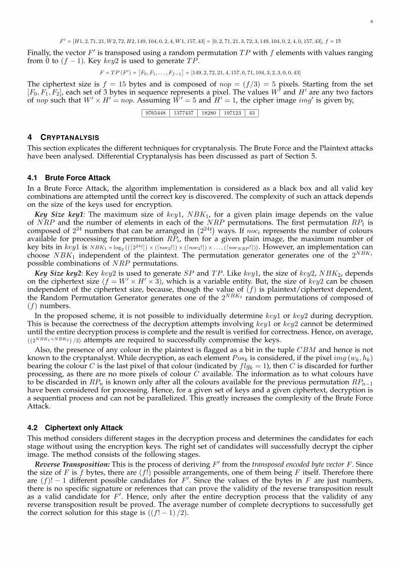
6
F ′ = [H1, 2, 71, 21, W2, 72, H2, 149, 104, 0, 2, 4, W1, 157, 43] = [0, 2, 71, 21, 3, 72, 3, 149, 104, 0, 2, 4, 0, 157, 43], f = 15
Finally, the vector F ′ is transposed using a random permutation TP with f elements with values rangingfrom 0 to (f − 1). Key key2 is used to generate TP .
F = TP (F ′) =[F0, F1, . . . , Ff−1
]= [149, 2, 72, 21, 4, 157, 0, 71, 104, 3, 2, 3, 0, 0, 43]
The ciphertext size is f = 15 bytes and is composed of nop = (f/3) = 5 pixels. Starting from the set[F0, F1, F2], each set of 3 bytes in sequence represents a pixel. The values W ′ and H ′ are any two factorsof nop such that W ′ ×H ′ = nop. Assuming W ′ = 5 and H ′ = 1, the cipher image img′ is given by,
9765448 1377437 18280 197123 43
4 CRYPTANALYSIS
This section explicates the different techniques for cryptanalysis. The Brute Force and the Plaintext attackshave been analysed. Differential Cryptanalysis has been discussed as part of Section 5.
4.1 Brute Force AttackIn a Brute Force Attack, the algorithm implementation is considered as a black box and all valid keycombinations are attempted until the correct key is discovered. The complexity of such an attack dependson the size of the keys used for encryption.
Key Size key1: The maximum size of key1, NBK1, for a given plain image depends on the valueof NRP and the number of elements in each of the NRP permutations. The first permutation RP1 iscomposed of 224 numbers that can be arranged in
(224!
)ways. If noci represents the number of colours
available for processing for permutation RPi, then for a given plain image, the maximum number ofkey bits in key1 is NBK1 = log2
((⌈224!
⌉)× (dnoc2!e)× (dnoc3!e)× . . . , (dnocNRP !e)
). However, an implementation canchoose NBK1 independent of the plaintext. The permutation generator generates one of the 2NBK1
possible combinations of NRP permutations.Key Size key2: Key key2 is used to generate SP and TP . Like key1, the size of key2, NBK2, depends
on the ciphertext size (f = W ′ ×H ′ × 3), which is a variable entity. But, the size of key2 can be chosenindependent of the ciphertext size, because, though the value of (f) is plaintext/ciphertext dependent,the Random Permutation Generator generates one of the 2NBK2 random permutations of composed of(f) numbers.
In the proposed scheme, it is not possible to individually determine key1 or key2 during decryption.This is because the correctness of the decryption attempts involving key1 or key2 cannot be determineduntil the entire decryption process is complete and the result is verified for correctness. Hence, on average,((
2NBK1+NBK2)/2
) attempts are required to successfully compromise the keys.Also, the presence of any colour in the plaintext is flagged as a bit in the tuple CBM and hence is not
known to the cryptanalyst. While decryption, as each element Posk is considered, if the pixel img (wk, hk)bearing the colour C is the last pixel of that colour (indicated by flgk = 1), then C is discarded for furtherprocessing, as there are no more pixels of colour C available. The information as to what colours haveto be discarded in RPn is known only after all the colours available for the previous permutation RPn−1
have been considered for processing. Hence, for a given set of keys and a given ciphertext, decryption isa sequential process and can not be parallelized. This greatly increases the complexity of the Brute ForceAttack.
4.2 Ciphertext only AttackThis method considers different stages in the decryption process and determines the candidates for eachstage without using the encryption keys. The right set of candidates will successfully decrypt the cipherimage. The method consists of the following stages.
Reverse Transposition: This is the process of deriving F ′ from the transposed encoded byte vector F . Sincethe size of F is f bytes, there are (f !) possible arrangements, one of them being F itself. Therefore thereare (f)! − 1 different possible candidates for F ′. Since the values of the bytes in F are just numbers,there is no specific signature or references that can prove the validity of the reverse transposition resultas a valid candidate for F ′. Hence, only after the entire decryption process that the validity of anyreverse transposition result be proved. The average number of complete decryptions to successfully getthe correct solution for this stage is ((f !− 1) /2).

7
Derivation of W and H: This step involves the extraction of the randomly placed 4 size bytes W1,W2, H1 and H2 in F ′. Since W and H are unknown, all possible width and height values have to beconsidered for decryption. There are
(fP4
)ways of choosing 4 out of a set of f bytes. Since 2 bytes
represent W or H , the plaintext can have a maximum of 65536 × 65536 pixels, which is not the casealways. If the plaintext supports a maximum size of 4096 × 4096, then the most significant byte of thewidth and the height cannot exceed the threshold value of 16. All values that exceed this threshold inthe higher byte can be discarded. Also, the set of bytes which result in a value 0 for any of W or H canbe discarded. This knowledge assists in eliminating all invalid byte combinations as candidates for thisstage. Assuming that there are z bytes with value zero and u bytes with value greater than the thresholdand if, M is the no. of combinations such that W or H = 0, T is the no. of combinations such that W2
or H2 > t and MT is the no. of combinations satisfying both M and T , the number of valid candidatesfor this stage is given by
V =f P4 −M − T + MT 1 (1)
where,- M = zP4 + 4 (f − z) (zP3) + 2 (zP2)
((f−z)P2
)- T = uP4 + 4 (f − u) (uP3) + 5 (uP2)
((f−u)P2
)+ 2 (u)
((f−u)P3
)- MT = 2 (u) (f − u) (zP2) + 2 (zP2) (uP2)
MT is added to V because these combinations are internally eliminated twice in the equation, once inM and one more time in T .
Retrieval of vectors Pos and CBM : For a given Reverse Transposition candidate and W and H values,the retrieval of Pos vector involves extracting (bw + bh + 1) bits for each of the W × H pixels, startingfrom the first byte of the Reverse Transposition candidate. Since CBM is concatenated to Pos, it can bederived by considering bytes that follow the Pos vector bytes. However, the retrieved Pos and CBMvector candidates has to satisfy the following conditions to be considered as a valid ones.
1) If Pos = (wk, hk), wk < W and hk < H , ∀ 0 ≤ k < (W ×H)2) The extracted and decoded tuple CBM is composed of exactly 224 bits.
Since wk and hk values are bit packed and not aligned to byte boundaries, the retrieval of these valuesfrom the Pos vector and the verification of the above condition involves huge number of bitwise oper-ations. If the above conditions are not satisfied, then the cryptanalyst can choose another set of 4 sizebytes or another Reverse Transposition candidate. For a valid candidate, the number of colours noc isgiven by the number of ’1’s in the retrieved CBM . At this point, though the cryptanalyst can verify thecandidature of Pos, CBM , W , H and noc, the correctness of these parameters cannot be verified.
Image Reconstruction: The Image Reconstruction process uses a set of random permutations and thevectors Pos and CBM to match each Posk with its colour. The number of permutations required andtheir composition depends on the candidate Pos vector and is different for each decryption attempt.If dnoci represent the number of colours available for the ith permutation and DNRP , the number ofpermutations required for a decryption attempt, then the cryptanalyst, for a given Pos vector candidate,needs to attempt a maximum of
((⌈224!
⌉)× (ddnoc2!e)× (ddnoc3!e)× . . .× (ddnocDNRP !e)
)combinations
of random permutations to verify if the ciphertext has been successfully decrypted.It shall be noted that none of the stages can be validated for correctness individually. Rather, for each
attempt in each stage, it is necessary to complete the entire decryption process to verify their validity.Hence, the time required for a successful attack is not the sum of the time required for each stage, buttheir product. Because of the multiplication of time needed for each stage and excessively large numberof iterations, it is highly impractical to break this algorithm without necessary information.
4.3 Chosen Plain Text AttackThe goal of Chosen Plain Text Attack (CPTA) is to reveal encryption information like the set of per-mutations RP1 through RPNRP , permutations TP and SP . The cryptanalyst has the knowledge of thealgorithm and is provided with an Encryptor that can encrypt any input plaintext with keys key1 and key2.The cryptanalyst has the ability to fabricate arbitrary plaintexts, which, when encrypted have the potentialto reveal encryption information. Though the intention of a typical CPTA is to reveal the encryptionkeys, in the proposed scheme, retrieval of keys key1 and key2 from RP s, TP and SP is immenselycomplex. Since the generation of a Random Permutations involve the usage of the keys as seeds of aCryptographically Secure Pseudo Random Number Generator, the process of key generation starting from thepermutations is practically impossible.
1. See Appendix for derivation
8
It can be noted from the previous sections that the permutations RP2 through RPNRP , TP and SPdepend on parameters which are derived based on the properties of the input plaintext. Also, for a givenkey, the PRNG generates different permutations based on the number of elements in the permutation.Hence, these permutations are rendered useless since they cannot be applied for other images. As a result,the only useful encryption information that the CPTA can potentially reveal is RP1 which depends onlyon the key.
Consider an input plaintext img1 with W = H = 1. The only pixel in the image, identified by img1 (0, 0),bears the colour C. Let img′1 be the encrypted image with width W ′ and height H ′, with each of theW ′ × H ′ pixels bearing any of the 224 colours. For such an image, NRP = 1 and Pos = [(0,0,1)] = 00100000 (5bits 0 padding). Since img1 is composed of only one colour, the colour bitmap would contain one entryof ’1’ and huge runs of ’0’s. Hence the only possible values CBM (digitally encoded - refer Section 2)bytes can take are 0, 1 and 255.
The first step in cryptanalysis is the reverse transposition operation to derive F ′ from F . It can benoted that there are ((f !)− 1) possible candidates for F ′. But with the knowledge that Pos = 00100000 andthat it precedes any other byte in F ′, all outcomes with the first byte value 00100000 are candidates forF ′. Since the first byte is fixed, the number of such outcomes are (f − 1)!. It is clear from the previoussection that it is not possible to discern until the entire decryption process that which of the (f − 1)!candidate outcomes is F ′. The next step is to pick the 4 size bytes from the ciphertext. Since the positionsof the size bytes are unknown, the cryptanalyst has to choose a set of 4 bytes having the values 0, 1, 0, 1.Though there is a possibility that the cryptanalyst choses an invalid size byte set, the maximum erroran invalid size byte choice can introduce is the shift of the only 1 in the CBM , which further results inan incorrect position of C in RP1. It can be noted that such an error can affect only CBM because bulkof img′1 is CBM with only a byte occupied by Pos. Assuming W1, W2, H1 and H2 are correctly chosenand removed from the candidate, the cryptanalyst now has the task of deriving the position of C in RP1,which can be any of the 224 different possible positions.
It is apparent that only when the cryptanalysis results in img1, that the correctness of the reversetransposition operation, choice of the size bytes and that of RP1 can be proved. But in this attack, all the224 choices of RP1 will result in img1 rendering this attack useless. The following example explains thisphenomenon.
Let one of the reverse transposition candidates take the following form, F ′ : [32, 1, 1, 255, 0, 255 . . .], indicatingthat the Pos value is 32(00100000), the first bit of the CBM is 1, followed by a sequence of 510 0s andso on. Since the first element of CBM is 1, the attempt in which RP1 has C as its first colour results inimg1. Similarly if, F ′ : [32, 0, 1, 1, 255, 0, 255 . . .], usage of a candidate RP1 having C as its second colour resultsin img1. Hence, with the above attack, it is not possible to uniquely determine the position of C in RP1.
Consider input plaintext img2 with W = 2 and H = 1. The two pixels in the image, identified byimg2 (0, 0) and img2 (0, 1), bear colours C1 and C2 respectively. NRP = 1. Let img′2 be the encryptedimage with width W ′ and height H ′, each of the W ′×H ′ pixels bearing any of the 224 colours. Dependingon whether C1 appears before or after C2 in RP1, the position vector takes the following form.
1) Colour order C1 C2, Pos : [(0,0,1),(0,1,1)] = 00101100 (2 bits 0 padding)2) Colour order C2 C1, Pos : [(0,1,1),(0,0,1)] = 01100100 (2 bits 0 padding)Since the cryptanalyst does not have the knowledge of RP1, all reverse transposition results that have
their first byte value either 00101100 or 01100100 become candidates for F ′. In this case it is straightforward to determine the relative positions of C1 and C2. The occurrence of a byte 00101100 reveals thatthe colour order is C1 C2 and of 01100100, colour order C2 C1. The cryptanalyst may get confused ifboth the bytes occur in the cipher text img′2. In general, the cryptanalyst can determine the colour orderonly if there are no byte sequences in the ciphertext pertaining to other colour orders. In the case of img2,since the plain text is made of only two colours, there can be only two 1s in CBM , with huge runs of0s. As a result, the CBM is composed of bytes with values 0, 1 and 255, making the probability of theoccurrence of both the above said bytes 00101100 and 01100100, almost 0.
It is impossible to derive the absolute positions of C1 and C2 because of the reason explained in theprevious example, that multiple choices of RP1 for decryption result in img2.
Though the previous attack could not reveal the absolute positions of C1 and C2, it reveals theirrelative positions. The relative position of a colour C3 with respect to C1 and C2 can be derived if animage img3 with three pixels bearing C1, C2 and C3 is cryptanalysed. The following maps the variousPos values with the relative positions of the colours, assuming C2 occurs before C1.
1) Colour order C3 C2 C1, Pos : 01010011 000100002) Colour order C2 C3 C1, Pos : 00110101 000100003) Colour order C2 C1 C3, Pos : 00110001 01010000
9
For a given order of C1 and C2, C3 can take three different positions resulting in three different colourpatterns and Pos vectors. The cryptanalyst has to search for any of the byte patterns to derive the relativepositions of the three colours.
It shall be noted that usage of an image with only C1 and C3 or C2 and C3 would have revealedC3’s relative position with respect to only C1 or C2 respectively, while it is important to find the relativeposition of C3 w.r.t both C1 and C2. Hence, it is necessary to consider all the other n− 1 colours whenthe relative position of a colour Cn in the permutation is being determined.
The above process can be extended for all the 224 colours of RP1, which in totality, reveals the absolutepositions of all the colours of RP1. But, as the number of colours and pixels increase in the plaintext,this attack decays into a Brute Force Attack. This is because of the following reasons.
1) As the number of colours and the pixels increase, the entries in Pos for each pixel spans more thana byte increasing the number, and the complexity of a byte pattern search that reveals the colourorder.
2) The number of 1s in the CBM increases resulting in non-standard (values other than 0, 1 and 255)byte entries which further confuse the cryptanalyst in uniquely determining the byte patterns.
3) There are n different combinations of byte patterns that needs to be analysed to uniquely determinethe relative position of the nth colour w.r.t n−1 other colours whose relative positions have alreadybeen determined, while it requires to analyse n! combinations of byte patterns, to reveal the relativepositions of n colours, if the relative order of any of the n−1 colours is not known. The cryptanalystis forced to cryptanalyse sequentially.
4) There is a high probability that a byte pattern specifying multiple colour orders exist in the ciphertextdue to increase in the number of entries of the Pos vector and non-standard byte values in CBM .This confuses the cryptanalyst as to which order to choose to continue cryptanalysis.
5) The cryptanalyst not only has to analyse the ciphertext to reveal the colour order RP1 used, buthas to further verify for byte patterns corresponding to other colour orders to indicate or invalidatetheir presence.
Hence, as the colours and pixels increase, the cryptanalytic complexity converges to that of a BruteForce Attack and in most cases fail to provide valid encryption information due to presence of bytes thatspecify multiple colour orders. The above technique requires 224 − 1 cryptanalytic attempts to revealRP1, each attempt being higher in complexity than the previous one. The number of combinations ofbyte patterns that needs to be analysed to reveal the colour permutation is given by A = 2 + 3 + . . . + 224.
The above attack can be extended for m permutations by generating a plaintext where each colouris borne by m pixels. But the analysis is rendered useless since the revealed permutations are plaintextdependent and can not be used for other images.
4.4 Known Plain Text AttackThe goals and limitations of CPTA are applicable to Known Plain Text Attack KPTA. In a KPTA the crypt-analyst has the access to a plaintext image img and its corresponding ciphertext img′. The cryptanalysthas the knowledge of width W and height H , the colour value of W ×H pixels and hence NRP .
Among the ((f !)− 1) different ways of arranging the ciphertext bytes, the reverse transposition resultswhich satisfy the following conditions, are candidates for the vector PB.
1) The 4 size bytes extracted have values of W1, W2, H1 and H2.2) Within the extracted Pos vector, wk < W and hk < H of Posk, ∀ 0 ≤ k < (W ×H)3) The first noc entries in Pos should provide position information of pixels bearing noc distinct colours4) The extracted and decoded tuple CBM is composed of exactly 224 bits.5) The tuple CBM has noc number of 1s.
As indicated earlier, wk and hk values are not aligned to byte boundaries. To verify conditions 2 and 3,bits have to be extracted from multiple bytes involving huge number of bitwise operations and integercomparisons. It requires 4 integer comparisons per Pos entry to verify if condition 2 and 3 are satisfiedand 1 comparison for the first noc entries to verify condition 3. Since there are W ×H Pos entries, thenumber of integer comparisons IC is
IC = 4 (W ×H) + noc
Verifying if a reverse transposition result is a valid candidate involves huge bit processing and integercomparisons.
Since there can be multiple size byte sets for a reverse transposition result, for a worst case, the aboveverification has to be carried out for each such size byte choice of all the (f)! − 1 possibilities. If for a

10
plaintext image, B is the number of ways in which the W1, W2, H1 and H2 can be chosen, and ∆ is thetime to verify all the conditions for an attempt, then approximately
(((f)!− 1)× 2B ×∆) /2
time units are required to derive the valid candidates for PB. The time ∆ is halved since not all attemptsrequire complete verification.
Since in this attack the colour of all the pixels is known, CBM and padding bytes can be discarded.Hence all candidates of PB directly translates to candidates of Pos. Let n < (W ×H)! be the number ofcandidates for vector Pos. Each of the n candidates for vector Pos result in n different pixel orders andhence n different colour orders for permutations RP1 through RPNRP . There is no deterministic criteriafor accurately deriving the colour orders, because, irrespective of the order of the Pos entries, all thecandidates result in correct decryption as the pixel colours are already known. Hence, KPTA results inmultiple valid colour orders and fails to generate valid encryption information.
It is seen that the KPTA is unable to accurately determine the permutations RP1 through RPNRP
as it results multiple colour orders for a given plain image. Hence, KPTA is rendered useless sincethe very purpose of the attack is defeated. Also, even if the cryptanalyst succeeds in deriving theset of permutations used for encryption, the same set cannot be used to decrypt other images as thepermutations are plaintext dependent.
A minor change in the algorithm greatly increases the cryptanalytic complexity. Based on a randombit pattern of W ×H bits, the decision of placing the pixel width or the height as the first entity of eachof the (W ×H) Pos entries is made. For example, bit value 1 for kth bit, results in Posk = (hk, wk, (1/0))and Posk = (wk, hk, (1/0)), for value 0. This enhancement results in huge increase in the cryptanalyticcomplexity.
5 STRENGTH OF THE ALGORITHM
The previous sections describe the number of unit operations and the time required to decrypt theciphertext based on the availability of plaintext information and resources for cryptanalysis. In the process,they also provide the Objectival Strength in terms of mathematical equations. This section provides theSubjectival Strength of the algorithm based on the properties of Pixel Property Separation.
Pixel Property Separation: Consider that the cryptanalyst is in possession of key2. Then, the reversetransposition and the extraction of the size bytes can be successfully carried out, resulting in the vectorPB. The vector PB contains the pixel position information and a combination of 1s and 0s indicatingthe presence of any of the 224 colours, as part of CBM . Each entry of the pixel position informationPos, is composed of entities to describe only the positions of the pixel but not its colour. The entire Posvector consists of the position values of all the W ×H pixels in the plaintext. This information is obvioussince the cryptanalyst at this stage has the knowledge of W and H , and can derive the positions of allthe pixels in the image. Since the vector CBM is composed of bit values, it conveys no information asto the actual colours of the plaintext. Most part of the vector PB contains information which is not ofmuch use to the cryptanalyst. If key1 is compromised, the cryptanalyst can only derive RP1 since it iscomposed of 224 elements. It is not possible to derive the rest of the permutations as they are plaintextdependent. Without key2, the ciphertext can not be reverse transposed. Also, no information regardingthe values of the 4 size bytes can be derived. Without the size of the plaintext it is not possible to derivethe Pos and CBM vectors, making it impossible to discern the pixel position-colour association.
Plaintext Size Concealment: The size of the plain image is concealed by randomly placing the sizebytes within the ciphertext. It is clear from the earlier sections that the cryptanalytic complexity greatlyincreases because of non-availability and the random placement of the original width and height.
Plaintext Dependent Permutation Generation: It is noted from Section 3 that NRP and the permu-tations RP2 through RPNRP are plaintext dependent. The composition of these permutations dependon the number of colours available for processing. This renders the technique robust against plaintextattacks as described in the previous sections.
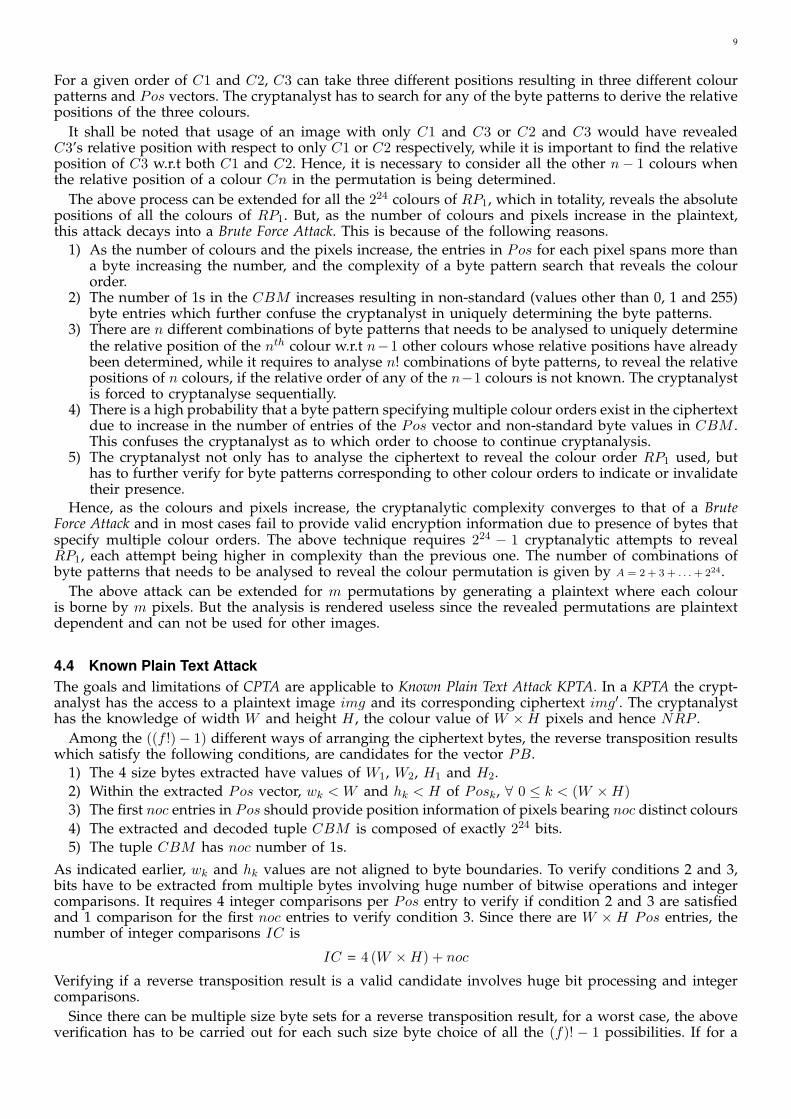
Cryptanalytic Error Avalanche Effect (CEAE): The CEAE results in a decrypted image with huge errorsfor a small error during any stage of the decryption process. Since the entries of the vectors Pos andCBM are closely packed, a small error manifests into considerable deviations of the decrypted imagefrom the original plaintext. For example, for a 512×512 image, 9 bits are required to represent any widthor height. Figure 3a depicts a byte pattern in Pos of such an image and their usage in creating Posentries. During decryption, the above byte pattern results in the vector Pos = [. . . , (2, 183, 0), (305, 235, 0), . . .].But, if the second byte is missing either due an error in reverse transposition or an error in choosingthe size bytes, there is a huge difference in the entries of Pos. Figure 3b illustrates the vector with the

11
Fig. 3: Cryptanalytic Error Avalanche Effect - a. Original b. Erroneous
byte B2 missing. The erroneous byte pattern results in Pos = [. . . , (3, 332, 0), (373, 282, 0), . . .]. It shall be noted thatwith such a decryption error, the number of bits retrieved from a byte and the purpose of the retrievalis disturbed, which continues until all the W ×H entries are retrieved. In the process, some of the bitsfrom CBM end up in the Pos entries, resulting in a huge error both in Pos and in CBM .
Consider the vector, CBM : [1, 167, 25, 34, 123 . . .] . The vector indicates that the first 167 bits in CBM are 1s,followed by runs of 25 0s, 34 1s and 123 0s. If the byte with value 167 is missed due to reasons statedabove, the semantics of the vector is completely altered. The modified vector is composed of a first runof 25 1s, followed by 34 0s and 123 1s, indicating the presence of non existing colours and invalidatingexisting colours, disturbing the colour-position correlation in the decrypted image.
Confusion and Diffusion: The proposed algorithm is characterised by good Diffusion of plaintext bitsin the ciphertext. If a bit in the plaintext changes, the colour of exactly one pixel changes from Co to Cn.This replaces an entry in the Pos vector. The position of the new entry depends on whether Cn alreadyexists in the plain image or is a new colour. If Cn is a new colour, then the entry is made within the firstnoc (number of distinct colours in plain image) entries in Pos. The entry corresponding to Co is removed.The insertion and removal of entries has a cascading effect resulting in a shift of the subsequent entries.If Cn is not already present in the plaintext, CBM is also altered to accommodate Cn, changing exactly 2bits. Even if only two bits are altered in CBM , the run composition is altered resulting in a considerablechange. Such an effect may induce a change in W ′ and H ′. These bit alterations are randomly dispersedin the entire ciphertext by the final byte transposition. Strict Plaintext Avalanche Criterion (SPAC), for afixed key to satisfy, each bit of the ciphertext block changes with the probability of one half, wheneverany bit of the plaintext block is complemented. The insertion - removal of entries in Pos and the bit runalteration in CBM affect an approximate 50% of bits, satisfying SPAC.
Differential Cryptanalysis attempts to develop a pattern or a relationship between unit changes inplaintext and the ciphertext. Higher the diffusion, higher is the complexity of a differential attack. Agood measure of diffusion is the Percentage Inequality PI of two ciphertexts img′ and img′′, the formerderived from the original plaintext img and the latter by an unit change on img. The following equationdefines PI ,
PI = (NDP × 100) / (W ×H) (2)
where NDP is the number of pixels that differ in img′′ as compared to the corresponding pixels in img′.If the value of PI between two ciphertexts is high, then Diffusion is said to be high. Also, if this value,for various such ciphertext pairs changes randomly without exhibiting a pattern, a differential attackbecomes practically impossible. Figure 4a depicts PI values for 20 different ciphertexts measured against
Fig.4: a. Percentage Inequality b. Variation of W ′ and H ′ against key1 for Lena Imagethe plaintext-ciphertext pair in Figure 5a-5b. It shall be noted that the variation of PI ranges from 0.3%to 97% and that it does not follow any pattern.

12
While Diffusion complicates the relationship between the plaintext and the ciphertext, Confusion achievesthe same between the ciphertext and the encryption key. In the proposed scheme, the key is not directlyoperated on the plaintext bits, rather used as seeds to generate random permutations. The randompermutations are used as subkeys to arrange pixel position information and generate colour bit map,altering the basic structure of the plaintext. The final random transposition of ciphertext bytes obfuscatesthe relation between pixel position ordering on key1. Cryptographically Secure Random Permutationsare characterised by a huge change in the permutation order, for a small change in the seed, complicatingthe Key-Ciphertext relationship. Also, it has been discussed that retrieval of keys from the permutationsRP s, TP and SP is practically impossible. This complicates the key-ciphertext relationship, resulting inhigh degree of Confusion. Strict Key Avalanche Criterion (SKAC), for a fixed plaintext block, each bit ofthe ciphertext block changes with a probability of one half when any bit of the key changes. A one bitchange in the key, would generate totally unrelated random permutations, resulting in a huge change inthe ciphertext, satisfying SKAC. As key1 changes, bit pattern in the CBM changes altering the contentand the size of the ciphertext. This completely alters the values of W ′ and H ′. Figure 4b illustrates thechange in W ′ and H ′ due to unit changes in key1. It can be noted that the change in W ′ and H ′ doesnot follow any pattern.
6 SIMULATION RESULTS
This section provides the experimental results of a basic-unoptimised implementation of the proposedscheme. The experiments were conducted on a 1.83GHz Intel Centrino Duo Processor with 1GB memory.
Figure 5 depicts the input image ’Lena’ and its encrypted form. The values of key1 and key2 are 0.298760and 0.514984 respectively. It shall be noted that the encrypted image (b) suggest the change in the widthand height of the ciphertext. Figures Rp and Re, Gp and Ge, Bp and Be illustrate the histograms of the R,G and B components respectively of the plaintext and ciphertext. It shall be noted that the histograms ofthe encrypted image suggest an uniform distribution and significant difference of the RGB componentsof the ciphertext as compared to the plaintext, a desirable property of any encryption scheme.
Fig 5: Lena - Plain Image, Cipher Image and RGB Histogram of plain and cipher image
Images of different width and height combinations have been considered for experiments, each beingencrypted with a different set of keys. Table 1 presents the plaintext and the ciphertext properties, theencryption time (ET) and the decryption time (DT) in seconds for a selected set of images with differentsize and NRP requirements.
Img W ×H W ′ ×H′ NRP p ET DT
1 512× 512 535× 491 21 0 5.0 4.72 640× 480 602× 507 703 2 5.5 4.83 1024× 786 1141× 658 1991 1 6.4 5.44 2816× 2112 2841× 2291 258 41 19.5 14.85 3648× 2736 4395× 2404 5712 17 22.0 19.1
Table 1 - Encryption - Decryption Time
7 CONCLUSION AND FUTURE WORK
In this paper, a new symmetric encryption technique based on Pixel Property Separation has beenproposed. The cryptanalytic complexities of various attacks also have been discussed. Together with theobjectival strength in terms of mathematical equations, the paper also presents subjectival strength basedon the principles of Pixel Property Separation. The results show that the algorithm possesses high securityand is characterised by good confusion and diffusion. Plaintext attacks fail to provide valid encryptioninformation and these attacks are rendered useless because of the usage of plaintext dependent RandomPermutations. Given its high cryptanalytic complexity, the proposed technique is particularly suitable forapplications involving secure storage and transmission of sensitive data with longer lifetime. Also, thealgorithm is not limited to images, it can be easily adapted for any kind of digital data.
13
The flavour of the algorithm specified in this paper assumes a 24 bit RGB colour. Future work includesresearch on the number of bits used to represent a colour. 24 bit values need not always result in optimalciphertexts when the algorithm is applied for digital data other than images. Also,the enhancementproposed as part of Section 4 can be analysed to derive the factor by which the cryptanalytic complexityis increased.
APPENDIX
DERIVATION: NRP
NRP can be mathematically defined as follows. The minimum value of NRP is 1. This is because, evenif all the pixels bear the same colour (when no colour order can be defined), RP1 is necessary to createCBM . In case of multicoloured images, If the pixels are grouped based on the colour and sorted on thegroup size, then NRP is the size of the group second in the list starting from the maximum size. If thereare multiple sets with the maximum number of pixels, then NRP is the size of one such set. If a (i),∀ 0 ≤ i < 224 RGB colours, denotes the number of pixels of colour i, then NRP is given by the following.
1) pixmax = max{
a (0) , a (1) , . . . , a(224 − 1
)}2) Multiset U =
{i : a (i) = pixmax, ∀ 0 ≤ i < 224
}3) pixsmax =max
({a (i) ,∀ 0 ≤ i < 224
}− {pixmax}
)4)
NRP =
pixmax, size (U) ≥ 2
pixsmax, size (U) = 1
1, otherwise
MATHEMATICAL MODEL OF ENCRYPTION ALGORITHM
The encryption algorithm encrypts plain image img with width W , height H and (W ×H) ≥ 1. img (x, y),0 ≤ x < W , 0 ≤ y < H , be the 24 bit RGB colour level of img at the position (x, y). The scheme is a 2 keySecret Key Algorithm. It operates on the input plain image img, the two keys key1 and key2 and generatesthe encrypted image img′ with (W ′ ×H ′) pixels. The proposed encryption scheme is defined as follows.Note that the pixels of the plain image are always scanned from Left to Right and from Top to Bottom, asin a Raster Scan. Let
1) noc represent the number of distinct colours in plain image img2) function b indicate the presence of any colour C in img. Value b (C), ∀ 0 ≤ C < 224 colour values,
is ’1’ if at least one pixel in img bears C, ’0’, otherwise.3) function q be such that q (C), ∀ 0 ≤ C < 224 RGB levels, denotes a number ne, such that, at any
point in the encryption process, exactly ne number of pixels of colour C have been placed in thePos vector. Note that, (0 ≤ q (C) ≤ a (C)) when (b (C) = 1) and (q (C) = 0) when (b (C) = 0)
4) function GetCol be such that for any integer i ≥ 0, GetCol (i) returns the (i + 1)th colour Ci fromthe vector CV (depicted in Figure 1), such that there exists atleast one pixel bearing Ci, which isyet to be placed in the Pos vector.
5) function GetPos be such that for any colour 0 ≤ C < 224, GetPos (C, k) returns Posk, the (k + 1)th
entry of the Pos vector, composed of (x, y, flg) values of a pixel bearing colour C. This function isdefined as follows:
1. q (C) = q (C) + 1, if (b (C) = 1) ∧ (q (C) ≤ a (C))
2. noc = noc− 1, if (b (C) = 1) ∧ (q (C) = a (C))
3. Posk ={ (
wq(C), hq(C), 0), if (b (C) = 1) ∧ (q (C) < a (C))(
wq(C), hq(C), 1), if (b (C) = 1) ∧ (q (C) = a (C))
where wq(C) and hq(C) represent respectively the width w and the height h of the q (C)th pixel suchthat img
(wq(C), hq(C)
)= C
The Encryption Algorithm is defined as follows:
Step 1: Create the Pos vector [Pos0, Pos1, . . . , PosW×H−1] by the following three steps. Initially, k = 0,n = 2. k is incremented after each Pos entry
1. Posk = GetPos (CV [RP1 [j]] , k) , ∀ 0 ≤ j < 224, where RP1 = RP(key1, 0, 224
)2. Posk = GetPos (GetCol (RPn [j]) , k) , (∀ 0 ≤ j < noc) and (∀ 2 ≤ n < NRP ), where any RPn = RP (key1, n, noc)
3. Posk = GetPos (GetCol (0) , k), ∀ k < (W ×H)

14
Step 2: Create CBM =[B0, B1, . . . , B224−1
], where any Bj = b (RP1 [j]), ∀ 0 ≤ j < 224
Step 3: Assuming Pos and CBM are digitally represented, Create PB = [Pos, CBM ]. Let pb be the sizeof vector PB.
Step 4: Let (p) be the number of padding bytes in the encrypted image. The padding bytes are given bythe vector P = [P0, P1, . . . , Pp−1]. Create PB′ = [PB, P0, P1, . . . , Pp−1]. (pb + p) gives the size of PB′
Step 5: Insert W1, H1, W2 and H2 within vector PB′, at positions given by SP [0], SP [1], SP [2] and SP [3]
respectively, to create vector F ′, composed of (pb + p + 4) bytes. SP = RP (key2, 0, (pb + p))
Step 6: Shuffle F ′ using permutation TP to create F =[F0, F1, . . . , Ff−1
], where any Fi = F ′TP [i]
. ChooseW ′ and H ′ such that f = (W ′ ×H′ × 3) = (pb + p + 4). TP = RP (key2, 1, f)
Step 7: Create encrypted image img′ of size W ′ ×H ′,img′ (x, y) = [Fi, Fi+1, Fi+2], where i = (x×W ′ × 3) + (y × 3), ∀ 0 ≤ x < W ′, 0 ≤ y < H′
img′ (x, y) is represented as a 24 bit number with Fi being the MSB. Number of pixels in img′ isnop = (W ′ ×H′) /3.
Step 8: Choose any two integral factors nop1 and nop2 of nop such that (nop1 × nop2) = nop. Then W ′ = nop1
and H′ = nop2. Note that this step is optional.
DERIVATION: M , T AND MT
Number of invalid size byte sets that can be chosen from a bin of f bytes, of which z bytes carry value0 and u bytes carry value greater than threshold t is derived as follows.
Let Bn be the nth byte chosen. Note that B1 = W1, B2 = H2, B3 = W2 and B4 = H2. Let Z represent abyte with value 0, and N , a byte with a non-zero positive value. It shall be noted that m = (f − z) arethe number of non-zero bytes available. There are (z) ways to choose the first Z, (z − 1) ways for thesecond and so on. Similarly (m) ways for the first N, (m− 1) ways for the second and so on.
Since 4 bytes have to be randomly chosen from the bin, there can be 16 distinct possibilities, ofwhich some are invalid. Byte combinations which have both B1 = 0 and B3 = 0 or both B2 = 0 andB4 = 0 result in a value 0 for W or H respectively. Such combinations shall be discarded. Invalid bytecombination B1B3B2B4 that result in value W or H = 0 and the number of ways Num in which eachinvalid combination be chosen as a size byte set, has been depicted in the Table 2.
B1B3B2B4 NumZZZZ (z) (z − 1) (z − 2) (z − 3)
ZZZN (z) (z − 1) (z − 2) (m)
ZZNZ (z) (z − 1) (m) (z − 2)
ZZNN (z) (z − 1) (m) (m− 1)
ZNZZ (z) (m) (z − 1) (z − 2)
NZZZ (m) (z) (z − 1) (z − 2)
NNZZ (m) (m− 1) (z) (z − 1)
Table 2. No. of invalid size byte choices with H = 0 or W = 0
Summing the invalids, the number of 4 byte sets M , resulting in a value 0 for both or any of W andH is
M =z P4 + 4 (f − z) (zP3) + 2 (zP2)((f−z)P2
)On the same lines, the number of 4 byte sets T , resulting in W2 > t or H2 > t can be derived. If L
represents a byte B < t, and G, a byte B > t, all byte combinations which have B3 > t or B4 > t likeLGGG and LLLG are invalid. Adding all such invalid combinations, the value of T is
uP4 + 4 (f − u) (uP3) + 5 (uP2)((f−u)P2
)+ 2 (u)
((f−u)P3
)Byte combinations which qualify under both the above mentioned categories of invalid size byte sets,
like ZZLG, are invalidated twice. The number of such combinations MT have to be subtracted once fromM + T . MT is defined by the following equation.
MT = 2 (u) (f − u) (zP2) + 2 (zP2) (uP2)
15
REFERENCES
[1] W. Stallings, Cryptography and Network Security principles and practices, third ed.: Pearson Education, 2003.
[2] D. Knuth, The Art of Computer Programming, Volume 2: Seminumerical Algorithms, Reading, MA: Addison-Wesley, 1998.
[3] N.D. Jorstad, L.T. Smith, Jr., “Cryptographic Algorithm Metrics,” Institute for Defense Analyses Science and Technology Division , January. 1997.
[4] C. Shannon, “Communication Theory of Secrecy Systems,” Bell Systems Technical Journal, no. 4, 1949.
[5] J. Cheng; J.I. Guo, “A new chaotic key-based design for image encryption and decryption,” The 2000 IEEE International Symposium on Circuitsand Systems, 2000. Proceedings. ISCAS 2000 Geneva, vol.4, no. 4, pp. 49 - 52, May. 2000.
[6] D. A. Osvik, A. Shamir, E. Tromer, Cache Attacks and Countermeasures: the Case of AES, November, 2005. available athttp://theory.csail.mit.edu/t̃romer/papers/cache.pdf.
[7] SJ. Li and X. Zheng, “Cryptanalysis of a chaotic image encryption method,” The 2002 IEEE International Symposium on Circuits and SystemsProceedings 2002. ISCAS 2002 Scottsdale, Arizona, vol. 1, 2006
[8] R. B. Davies, Newran02C - a random number generator library, April, 2006. available at http://www.robertnz.net/.
[9] Anatoliy Kuznetsov, D-Gap Compression, 2002. available at http://bmagic.sourceforge.net/dGap.html.
[10] S.K. Sahni, Data Structures, Algorithms, and Applications in C++,, Second Edition, McGraw Hill, NY, 2005.
[11] Shiguo Lion, Jinsheng Sun and Zhiquan Wang, “A Novel Image Encryption Scheme Based-on JPEG Encoding,” Proceedings of the EighthInternational Conference on Information Visualisation (IV04), 2004
[12] J.A. Munoz Rodrguez and R. Rodrguez-Vera, “Image encryption based on phase encoding by means of a fringe pattern and computationalalgorithms,” REVISTA MEXICANA DE FISICA 52 (1), pp. 53-63, Feb. 2004
[13] A. Mitra, Y. V. Subba Rao and S. R. M. Prasanna, “A New Image Encryption Approach using Combinational Permutation Techniques,”INTERNATIONAL JOURNAL OF COMPUTER SCIENCE, vol. 1, no. 5, 2006
[14] W. Diffie and M. E. Hellman, “New Directions in Cryptography,” IEEE Transactions Information Theory, vol. 22, no. 6, pp. 644-654, Nov.1976.
[15] P. P. Dang and P. M. Chau, “Image Encryption for Secure Internet Multimedia Applications,” IEEE Transactions Consumer Electronics, vol.46, no. 3, pp. 395-403, Aug. 2000.
[16] R. B. Davies, COPACOBANA, a $10,000 DES cracker based on FPGAs by the Universities of Bochum and Kiel, December, 2006. available athttp://www.copacobana.org/.
[17] A. Fuster and L. J. Garcia, “An Efficient Algorithm to Generate Binary Sequences for Cryptographic Purposes,” Theoretical Computer Science259, pp. 679-688, 2001.
[18] Ronald L. Rivest, “The RC5 Encryption Algorithm,”, March. 1997.
[19] Min-Sung Koh, Esteban Rodriguez-Marek, Claudio Talarico, A NOVEL DATA DEPENDENT MULTIMEDIA ENCRYPTION ALGORITHMSECURE AGAINST CHOSEN-PLAINTEXT ATTACKS, ICME 2007.
Karthik Chandrashekar Iyer received the Bachelor of Engineering degree in Computer Science from the VishweshwarayaTechnological University, Karnataka, India in 2004. Currently, he is a Senior Engineer in the DSP Software Center, NXPSemiconductors (formerly Philips Semiconductors), Bangalore, India. His interests include Embedded Multimedia Systems,Digital Rights Management, Video Post Processing, Cryptography and Network Security.
Aravinda Subramanya received the Bachelor of Engineering degree in Computer Science from the VishweshwarayaTechnological University, Karnataka, India in 2004. Currently, he is a Senior Engineer in the DSP Software Center, NXPSemiconductors (Philips Semiconductors), Bangalore, India. His interests include Audio coding, Embedded MultimediaSystems, Vector Processors, Digital Rights Management, Cryptography and Network Security.