1. instr. guide, chaps. 1-13 - gd&t training, blueprint
TRANSCRIPT


Geometric Dimensioning and Tolerancing for Mechanical Design Instructors’ Guide 2
Geometric Dimensioning and Tolerancing
for Mechanical Design
Instructors’ Guide
Contents
1. Course Calendar 2. Lecture Topics 3. Study Guide and Problem Answers 4. Midterm and Final Exam 5. Midterm and Final Exam answers
Rev. 10/12/2020

Geometric Dimensioning and Tolerancing for Mechanical Design Instructors’ Guide 3
Course Calendar Week Date 1st Weekly Meeting 2nd Weekly Meeting 3rd Weekly Meeting
1 Admin. & Overview Lecture 1 Ch. 1 Lecture 2 Ch. 2
2 Lecture 3 Ch. 3 Lecture 4 Ch. 3 Lecture 5 Ch. 3
3 Lecture 6 Ch. 4 Lecture 7 Ch. 4 Lecture 8 Ch. 4
4 Lecture 9 Ch. 5 Lecture 10 Ch. 5 Lecture 11 Ch. 5
5 Lecture 12 Ch. 5 Lecture 13 Ch. 5 Lecture 14 Ch. 6
6 Lecture 15 Ch. 6 Lecture 16 Ch. 6 First Midterm Exam
7 Midterm Review Lecture 17 Ch. 7 Lecture 18 Ch. 7
8 Lecture 19 Ch. 7 Lecture 20 Ch. 7 Lecture 21 Ch. 8
9 Lecture 22 Ch. 8 Lecture 23 Ch. 8 Lecture 24 Ch. 8
10 Lecture 25 Ch. 9 Lecture 26 Ch. 9 Lecture 27 Ch. 9
11 Second Midterm Exam Midterm Review Lecture 28 Ch. 10
12 Lecture 29 Ch. 10 Lecture 30 Ch. 11 Lecture 31 Ch. 11
13 Lecture 32 Ch. 11 Lecture 33 Ch. 12 Lecture 34 Ch. 12
14 Lecture 35 Ch. 12 Lecture 36 Append. A Lecture 37 Append. A
15 Final Review Final Review Final Exam
Week Date 1st Weekly Meeting 2nd Weekly Meeting 3rd Weekly Meeting
1 Admin. & Overview Lecture 1 Ch. 1 Lecture 2 Ch. 3
2 Lecture 3 Ch. 3 Lecture 4 Ch. 3 Lecture 5 Ch. 4
3 Lecture 6 Ch. 4 Lecture 7 Ch. 5 Lecture 8 Ch. 5
4 Lecture 9 Ch. 6 Lecture 10 Ch. 6 Lecture 11 Ch. 6
5 Midterm Exam Midterm Review Lecture 12 Ch. 7
6 Lecture 13 Ch. 7 Lecture 14 Ch. 7 Lecture 15 Ch. 8
7 Lecture 16 Ch. 8 Lecture 17 Ch. 8 Lecture 18 Ch. 8
8 Lecture 19 Ch. 9 Lecture 20 Ch.10 Lecture 21 Ch.11
9 Lecture 22 Ch.11 Lecture 23 Ch.12 Lecture 24 Ch.12
10 Lecture 25 Ch. 12 Final Review Final Exam

Geometric Dimensioning and Tolerancing for Mechanical Design Instructors’ Guide 4
Lecture Topics No. Topics 1. Introduction
A. What is Geometric Dimensioning and Tolerancing B. When should GD&T be used?
1 C. Advantages of GD&T over coordinate dimensioning and tolerancing 1. The cylindrical tolerance zone 2. The maximum material condition 3. Datums specified in order of precedence
2. Dimensioning and Tolerancing Fundamentals A. Fundamental drawing rules B. Units of linear measurement
2 C. Specifying linear dimensions D. Specifying linear tolerances E. Interpreting dimensional limits F. Specifying angular dimensions G. Specifying angular tolerances H. Dimensioning and Tolerancing for CAD/CAM database models
3. Symbols, Terms, and Rules A. Geometric characteristic symbols B. The datum feature symbol
3 C. The feature control frame D. Reading the feature control frame E. Other symbols used with geometric tolerancing
4 F. Terms G. General rules 1. Rule #1
5 2. Rule #2 3. Pitch diameter rule
4. Datums A. Definition B. Application of datums
6 C. Immobilization of a part D. Datum feature selection E. Datum feature identification F. Inclined datum features G. Cylindrical datum features
7 H. Establishing datum features I. Irregular features of size J. Common datum features
8 K. Partial datum features L. Datum targets
Geometric Dimensioning and Tolerancing for Mechanical Design Instructors’ Guide 5
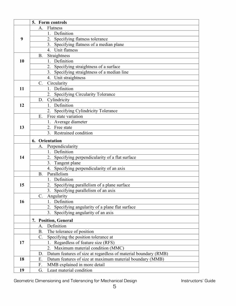
5. Form controls A. Flatness 1. Definition
9 2. Specifying flatness tolerance 3. Specifying flatness of a median plane 4. Unit flatness B. Straightness
10 1. Definition 2. Specifying straightness of a surface 3. Specifying straightness of a median line 4. Unit straightness C. Circularity
11 1. Definition 2. Specifying Circularity Tolerance D. Cylindricity
12 1. Definition 2. Specifying Cylindricity Tolerance E. Free state variation 1. Average diameter
13 2. Free state 3. Restrained condition
6. Orientation A. Perpendicularity 1. Definition
14 2. Specifying perpendicularity of a flat surface 3. Tangent plane 4. Specifying perpendicularity of an axis B. Parallelism 1. Definition
15 2. Specifying parallelism of a plane surface 3. Specifying parallelism of an axis C. Angularity
16 1. Definition 2. Specifying angularity of a plane flat surface 3. Specifying angularity of an axis
7. Position, General A. Definition B. The tolerance of position C. Specifying the position tolerance at
17 1. Regardless of feature size (RFS) 2. Maximum material condition (MMC) D. Datum features of size at regardless of material boundary (RMB)
18 E. Datum features of size at maximum material boundary (MMB) F. MMB explained in more detail
19 G. Least material condition

Geometric Dimensioning and Tolerancing for Mechanical Design Instructors’ Guide 6
20 H. Boundary conditions 21 I. “0” positional tolerancing at MMC
8. Position, Location 22 A. Floating and fixed fasteners 23 B. Projected tolerance zones C. Multiple patterns of features
24 D. Composite positional tolerancing E. Multiple single-segment positional tolerancing F. Nonparallel holes
25 G. Counterbored holes H. Noncircular features I. Symmetrical features
9. Position, Coaxiality A. Definition
26 B. Comparison between coaxiality controls C. Specifying coaxiality at MMC D. Composite control of coaxial features
27 E. Coaxial features controlled without datum references F. Tolerancing a plug and socket
10. Runout A. Definition B. Circular runout
28 C. Total runout D. Specifying runout and partial runout E. Multiple datum features F. Face and diameter datum features
29 G. Geometric control to refine datum features H. The relationship between feature surfaces I. Inspecting runout
11. Profile A. Definition B. Specifying profile tolerance
30 C. The application of datum features D. A radius refinement with profile E. Combining profile tolerances with other geometric controls F. Coplanarity
31 G. Profile of a conical feature H. Composite profile tolerancing I. Multiple single-segment profile tolerancing J Inspection
12. A Strategy for Tolerancing Parts 32 A. Feature of sizes located to plane surface features 33 B. Feature of sizes located to feature of sizes 34 C. A pattern of features located to a second pattern of features

Geometric Dimensioning and Tolerancing for Mechanical Design Instructors’ Guide 7
13. Graphic Analysis A. Advantages of graphic analysis
35 B. The accuracy of graphic analysis C. Analysis of a composite geometric tolerance
36 D. Analysis of a pattern of features controlled to a datum feature of size Appendix A. Concentricity & Symmetry A. Concentricity 1. The definition of concentricity 2. Specifying concentricity
37 3. Applications of concentricity B. Symmetry 1. The definition of symmetry 2. Specifying symmetry 3. Applications of symmetry
Geometric Dimensioning and Tolerancing for Mechanical Design Instructors’ Guide 8
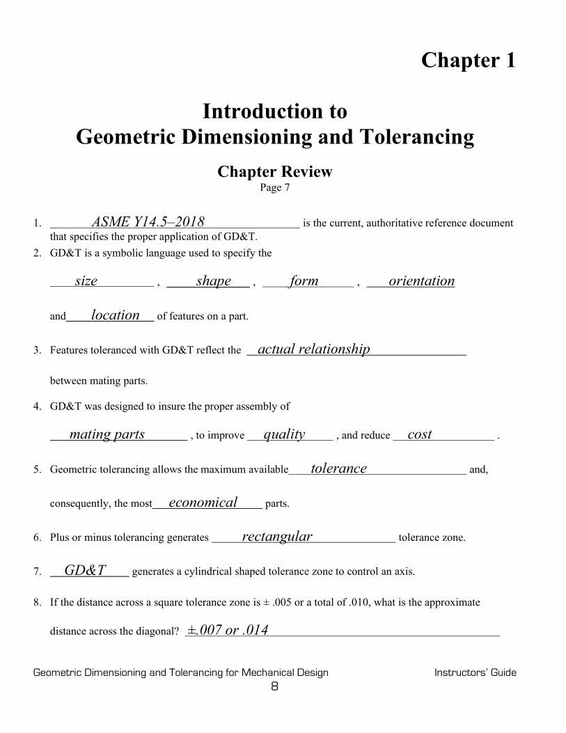
Chapter 1
Introduction to Geometric Dimensioning and Tolerancing
Chapter Review Page 7
1. ASME Y14.5–2018 is the current, authoritative reference document
that specifies the proper application of GD&T. 2. GD&T is a symbolic language used to specify the
size , shape , form , orientation
and location of features on a part.
3. Features toleranced with GD&T reflect the actual relationship
between mating parts.
4. GD&T was designed to insure the proper assembly of
mating parts , to improve quality , and reduce cost .
5. Geometric tolerancing allows the maximum available tolerance and,
consequently, the most economical parts.
6. Plus or minus tolerancing generates rectangular tolerance zone.
7. GD&T generates a cylindrical shaped tolerance zone to control an axis.
8. If the distance across a square tolerance zone is ± .005 or a total of .010, what is the approximate
distance across the diagonal? ±.007 or .014

Geometric Dimensioning and Tolerancing for Mechanical Design Instructors’ Guide 9
9. The cylindrical tolerance zone defines a uniform distance from true
position to the tolerance zone boundary.
10. Bonus tolerance equals the difference between the actual mating envelope size and the
maximum material condition .
11. While processing, a rectangular part usually rests against a datum reference frame
consisting of three mutually perpendicular intersecting planes.
Chapter 2
Dimensioning and Tolerancing Fundamentals Chapter Review
Page 15
1. Each feature must be a toleranced . Those dimensions specifically identified as
reference, maximum, minimum, or stock do not require the application of a tolerance.
2. Dimensioning and tolerancing must be complete so there is a full understanding of
the characteristics of each feature.
3. Dimensions must be selected and arranged to suite the function and mating relationship of a part and
must not be subject to more than one interpretation .
4. The drawing should define a part without specifying manufacturing methods.
5. An implied 90° angle always applies where centerlines and lines depicting
features are shown on orthographic views at right angles and no angle is specified.
6. An implied 90° basic angle always applies where center lines of features or surfaces shown at right angles on an orthographic view are located or defined by basic dimensions and no angle is specified.
7. Unless otherwise specified, all dimensions and tolerances are applicable at 68°F (20°C) . Compensation may be made for measurements made at other temperatures.
8. Unless otherwise specified, all dimensions and tolerances apply in a free state condition except for restrained non-rigid parts.

Geometric Dimensioning and Tolerancing for Mechanical Design Instructors’ Guide 10
9. Unless otherwise specified, all tolerances and datum features apply for the full depth
length and width of the feature.
10. Dimensions and tolerances apply only at the drawing level where they are
specified.
11. Units of linear measurement are typically expressed either in the inch system or the
metric system.
12. Where specifying decimal inch dimensions, a zero is never placed before the decimal
point for values less than one inch.
13. What are the three types of direct tolerancing methods?
Limit, Plus and Minus, and Geometric tolerancing 14. Where inch tolerances are used, a dimension is specified with the same number of decimal places as its
tolerance .
15. Where a unilateral tolerance is specified and either the plus or minus limit is zero, its dimension and
zero value must have the same number of decimal places as the other limit and the 0
value must have the opposite sign of the nonzero value.
16. For decimal inch tolerances, where bilateral tolerancing or limit dimensioning and tolerancing is used,
both values have the same number of decimal places.
17. Dimensional limits are used as if an infinite number of zeros followed
the last digit after the decimal point.
18. Angular units of measurement are specified either in degrees and decimal parts of a
degree or degrees, minutes, and seconds .
19. What two dimensions are not placed on the field of the drawing?
90° angles and zero dimensions 20. Dimensioning and Tolerancing for CAD/CAM Database Models. Dimensioning and tolerancing shall be
complete so there is full understanding of the characteristics of each feature. Values may be expressed in
an engineering drawing or in a CAD product definition data set specified in ASME
Y14.41.

Geometric Dimensioning and Tolerancing for Mechanical Design Instructors’ Guide 11
Chapter 3
Symbols, Terms, and Rules
Chapter Review Page 46
1. What type of geometric tolerances has no datum features? form
2. What is the name of the symbol used to identify physical features of a part as a datum feature and must
not be applied to centerlines, center planes, or axes? datum feature symbol
3. Datum feature identifying letters may be any letter of the alphabet except? I, O, & Q
4. If the datum feature symbol is placed in line with a dimension line or on a feature control frame
associated with a feature of size, the datum feature is what kind of feature?
a feature of size
5. One of the 12 geometric characteristic symbols always appears in the first
compartment of the feature control frame.
6. The second compartment of the feature control frame is the tolerance section.
7. The tolerance is preceded by a diameter symbol only if the tolerance zone is cylindrical .
8. Datum features are arranged in order of precedence .
Figure 3-36 Position feature control frame
9. Read the feature control frame in Fig. 3-36
1. The position tolerance requires that
2. The axis of the controlled feature

Geometric Dimensioning and Tolerancing for Mechanical Design Instructors’ Guide 12
3. Must lie within a cylindrical tolerance zone
4. 010 in diameter
5. At maximum material condition (MMC)
6. Oriented and located with basic dimensions to a datum reference frame
established by datum feature A, datum feature B at its maximum material
boundary, and datum feature C at its maximum material boundary.
10. The all around and between symbols are used with what control? the profile control
11. The all over symbol consists of two small concentric circles placed at
the joint of the leader connecting the feature control frame to the feature.
12. The continuous feature symbol specifies that a group of two or more
interrupted features of size are to be considered one single feature of size.
13. If no depth or remaining thickness is specified, the spotface is the minimum
depth necessary to clean up the surface of the specified diameter.
14. The independency symbol indicates that perfect form of a feature of size at MMC
or LMC is not required.
15. The unequally disposed symbol indicates
that the profile tolerance is unilateral or unequally disposed about the true profile.
16. The datum translation symbol indicates that a datum feature simulator
is not fixed and is free to translate within the specified geometric tolerance.
17. The actual mating envelope
is a similar, perfect, feature(s) counterpart of smallest size that can be contracted about an external
feature(s) or largest size that can be expanded within an internal feature(s) so that it coincides with the
surface(s) at its highest points.
18. A theoretically exact dimension is called a basic dimension .
19. What is the theoretically exact point, axis, line, plane, or combination thereof derived from the
theoretical datum feature simulator called? a datum

Geometric Dimensioning and Tolerancing for Mechanical Design Instructors’ Guide 13
20. A datum feature is a feature that is identified with either a
datum feature symbol or a datum target symbol.
21. A datum feature simulator is the
physical boundary used to establish a simulated datum from a specified datum feature.
22. A datum reference frame consists of three mutually
perpendicular intersecting datum planes and three mutually perpendicular axes at the intersection of
those planes.
23. What is the name of a physical portion of a part, such as a surface, pin, hole, tab, or slot?
A feature 24. A regular feature of size is a feature, which is associated with a directly toleranced dimension and takes
one of the following forms:
a) A cylindrical surface
b) A set of two opposed parallel surfaces
c) A spherical surface
d) A circular element
e) A set of two opposed parallel elements

Geometric Dimensioning and Tolerancing for Mechanical Design Instructors’ Guide 14
Figure 3-37 Geometric characteristic symbols 25. Write the names and geometric characteristic symbols where indicated in Fig. 3-37.

Geometric Dimensioning and Tolerancing for Mechanical Design Instructors’ Guide 15
All Around
Free State
All Over
Independency
Between
) Projected Tolerance Zone
Number of Places X Tangent Plane
Continuous Feature
Unequally Disposed Profile
Counterbore
Spotface
Countersink
% Radius
R
Depth/Deep
^ Radius, Controlled
CR
Diameter Ø Spherical Radius
SR
Dimension, Basic
Spherical Diameter
SØ
Dimension, Reference (60) Square
Dimension Not To Scale 15 Statistical Tolerance
Dimension Origin
! Datum Target
Datum Translation
Movable Datum Target
Arc Length
Target Point
Conical Taper
@ Dynamic Profile
Slope
# From - To
Figure 3-38 Geometric tolerancing symbols
26. Draw the indicated geometric tolerancing symbols in the spaces on Fig. 3-38.
F
I
P
T
CF U
SF
1.000
ST
A1Ø.500
A1
110

Geometric Dimensioning and Tolerancing for Mechanical Design Instructors’ Guide 16
27. The maximum material condition is the condition in which a feature of size
contains the maximum amount of material within the stated limits of size.
28. The least material condition is the condition in which a feature of size
contains the least amount of material within the stated limits of size.
29. What kind of feature always applies at MMC/MMB, LMC/LMB, or RFS/RMB?
A feature of size 30. The maximum material condition modifier specifies that the tolerance applies at the
maximum material condition size of the feature.
31. The MMC modifier indicates that the tolerance applies at the MMC size of the feature and that a bonus tolerance is available as the size of the feature departs from MMC towards LMC.
32. Bonus tolerance is the positive difference or the absolute value between the
actual mating envelope and the MMC.
33. The total positional tolerance equals the sum of the bonus
tolerance and the positional tolerance.
Refer to Fig. 3-39 to answer questions 34 through 41.
Hole Pin 34. What is the MMC? .515 .500 35. What is the LMC? .540 .495 36. What is the geometric tolerance? .010 .005 37. What material condition modifier is specified? MMC MMC 38. What datum feature(s) control(s) perpendicularity? A A 39. What datum feature(s) control(s) location? B & C B & C

Geometric Dimensioning and Tolerancing for Mechanical Design Instructors’ Guide 17
Figure 3-39 Refer to this drawing for questions 34 through 41
Internal Feature (Hole) Actual Feature
Size
MMC
Bonus
Geometric Tolerance
Total Positional Tolerance
MMC.515 .515 .000 .010 .010 .520 .515 .005 .010 .015 .525 .515 .010 .010 .020 .530 .515 .015 .010 .025 .535 .515 .020 .010 .030
LMC .540 .515 .025 .010 .035 Table 3-3 Total positional tolerance for holes
40. Using the drawing in Fig. 3-39, complete Table 3-3.
Geometric Dimensioning and Tolerancing for Mechanical Design Instructors’ Guide 18
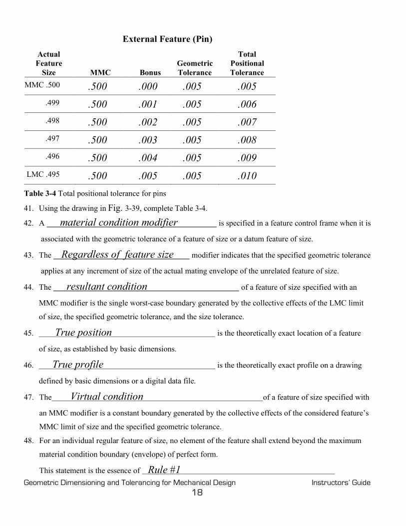
External Feature (Pin) Actual Feature
Size
MMC
Bonus
Geometric Tolerance
Total Positional Tolerance
MMC .500 .500 .000 .005 .005 .499 .500 .001 .005 .006 .498 .500 .002 .005 .007 .497 .500 .003 .005 .008 .496 .500 .004 .005 .009
LMC .495 .500 .005 .005 .010 Table 3-4 Total positional tolerance for pins
41. Using the drawing in Fig. 3-39, complete Table 3-4.
42. A material condition modifier is specified in a feature control frame when it is
associated with the geometric tolerance of a feature of size or a datum feature of size.
43. The Regardless of feature size modifier indicates that the specified geometric tolerance
applies at any increment of size of the actual mating envelope of the unrelated feature of size.
44. The resultant condition of a feature of size specified with an
MMC modifier is the single worst-case boundary generated by the collective effects of the LMC limit
of size, the specified geometric tolerance, and the size tolerance.
45. True position is the theoretically exact location of a feature
of size, as established by basic dimensions.
46. True profile is the theoretically exact profile on a drawing
defined by basic dimensions or a digital data file.
47. The Virtual condition of a feature of size specified with
an MMC modifier is a constant boundary generated by the collective effects of the considered feature’s
MMC limit of size and the specified geometric tolerance.
48. For an individual regular feature of size, no element of the feature shall extend beyond the maximum
material condition boundary (envelope) of perfect form.
This statement is the essence of Rule #1

Geometric Dimensioning and Tolerancing for Mechanical Design Instructors’ Guide 19
49. The local form tolerance increases as the actual local size of the feature departs from MMC toward
LMC
50. If features on a drawing are shown coaxial, or symmetrical to each other and not controlled for
location or orientation , the drawing is incomplete.
51. If there is no orientation control specified for a rectangle on a drawing, the perpendicularity is
controlled, not by the size tolerance , but by the
angularity tolerance.
52. Rule #2 states that RFS automatically applies, to individual tolerances of feature of
size and RMB automatically applies to datum features of size.
53. Each tolerance of orientation or position and datum reference specified for a screw thread applies to the
axis of the pitch diameter .
54. Each geometric tolerance or datum reference specified for gears and splines must designate the specific
feature at which each applies such as MAJOR DIA, PITCH DIA, or MINOR DIA
Problems Page 55
Figure 3-40 Feature control frames with material condition symbols: Prob. 1.
1. Read the complete tolerance in each feature control frame in Fig. 3-40, and write it below (Datum feature A is a feature of size).
A. 1. The position tolerance requires that 2. The axis of the controlled feature 3. Must lie within a cylindrical tolerance zone 4. .005 in diameter 5. At RFS 6. Oriented and located with basic dimensions to datum feature A at RMB

Geometric Dimensioning and Tolerancing for Mechanical Design Instructors’ Guide 20
B. 1. The position tolerance requires that 2. The axis of the controlled feature 3. Must lie within a cylindrical tolerance zone 4. .005 in diameter 5. At MMC 6. Oriented and located with basic dimensions to datum feature A at MMB
Figure 3-41 Geometric dimensioning and tolerancing terms: Prob. 2. 2. Place each letter of the items on the drawing in Fig. 3-41 next to the most correct term below. C Feature G Basic Dimension J Feature control frame
A MMC F Datum Feature D True Position
B LMC E Feature of Size H Datum feature symbol

Geometric Dimensioning and Tolerancing for Mechanical Design Instructors’ Guide 21
Chapter 4
Datums Chapter Review
Page 72
1. Datums are theoretically perfect points, axes, lines, planes, or a combination thereof .
2. Datums establish the origin from which the location or geometric characteristic of
features of a part are established.
3. Datums are assumed to exist in and be simulated by datum feature simulators.
4. A datum reference frame consists of three mutually perpendicular planes and three
mutually perpendicular axes at the intersection of those planes.
5. A part is oriented and immobilized relative to the three mutually perpendicular intersecting datum
planes of the datum reference frame in a selected order of precedence .
6. The primary datum feature contacts the datum reference frame with a minimum of three
points of contact that are not in a straight line.
7. Datum features are specified in order of precedence as they appear from left to right in the
feature control frame .
8. Datum feature letters need not be in alphabetical order.
9. The primary datum feature controls the orientation of the part .
10. When selecting datum features, the designer should consider features that are:
Functional surfaces, mating surfaces, readily accessible surfaces, and
surfaces that allow repeatable measurements .
11. Datum features must be identified with datum feature symbols
or datum targets and specified in a feature control frame.
12. Datum feature symbols must not be applied to centerlines, center planes, or axes .

Geometric Dimensioning and Tolerancing for Mechanical Design Instructors’ Guide 22
13. One method of tolerancing datum features at an angle to the datum reference frame is to place a datum
feature symbol on the inclined surface and
control that surface with an angularity tolerance and a basic angle.
14. A cylindrical datum feature is always associated with two theoretical planes
meeting at right angles at its datum axis.
15. The two kinds of features specified as datum features are:
Plane flat surfaces and features of size
16. Datum features of sizes may apply at regardless of material boundary, maximum
material boundary, or least material boundary
17. Where datum features of sizes are specified at RMB, the processing equipment must make
physical contact with the datum features.
18. Where features of sizes are specified at MMB, the size of the processing equipment has is equal to its
virtual condition with respect to the previous datum feature.
Figure 4-20 Datum feature of size: Questions 19 through 24.

Geometric Dimensioning and Tolerancing for Mechanical Design Instructors’ Guide 23
(Refer to Fig. 4-20 to answer questions 19 through 24.)
19. The 2-hole pattern is perpendicular to what datum feature? Datum feature A
20, The 2-hole pattern is located to what datum feature? Datum feature B
21. If inspected with a gage, what is the diameter of datum feature B on the gage? Ø 6.030
22. If inspected with a gage, what is the diameter of the 2 pins on the gage? Ø.500
23. If datum feature B had been specified at RFS, explain how the gage would be different.
Datum feature B would have to be a variable diameter like a chuck to make
physical contact with the outside diameter. 24. If datum feature B had been specified as the primary datum at RFS, explain how the gage would be
different.
Datum feature B would not only have to be a variable diameter, such as a
chuck, to make physical contact with the outside diameter, but the outside
diameter of the part, datum feature B, must align with the gage as well.
25. If a datum feature symbol is in line with a dimension line, the datum feature is the
feature of size measured by the dimension.
26. Where more than one datum feature is used to establish a single datum, the
datum reference letters and appropriate modifiers
are separated by a dash and specified in one compartment of the feature control frame. 27. Where cylinders are specified as datum features, the entire surface of the feature is considered to be the
datum feature .
28. If only a part of a feature is required to be the datum feature, a heavy chain line
is drawn adjacent to the surface profile and dimensioned with basic dimensions.
29. Datum targets may be used to immobilize parts with uneven or irregular surfaces
30. Costly manufacturing and inspection tooling
is required to process a part with datum targets.

Geometric Dimensioning and Tolerancing for Mechanical Design Instructors’ Guide 24
Problems Page 76
Figure 4-21 Placement of datum feature symbols: Prob. 1. 1. Attach the appropriate datum feature symbols on the drawing in Fig. 4-21.

Geometric Dimensioning and Tolerancing for Mechanical Design Instructors’ Guide 25
Figure 4-22 Placement of datum references in a feature control frames: Prob. 2. 2. Provide the appropriate datum feature symbols and complete the feature control frames on the drawing
in Fig. 4-22. (Two solutions suggested.)

Geometric Dimensioning and Tolerancing for Mechanical Design Instructors’ Guide 26
Figure 4-23 Datum features of size at MMB and RMB: Prob. 3. 3. Complete the feature control frames with datum references and material condition modifiers to reflect
the drawings in Fig. 4-23.

Geometric Dimensioning and Tolerancing for Mechanical Design Instructors’ Guide 27
Figure 4-24 Datum features located to the center planes of the drawing: Prob. 4. 4. Specify the appropriate datum feature symbols to locate the four-hole pattern to the center planes of the
drawing in Fig 4-24.

Geometric Dimensioning and Tolerancing for Mechanical Design Instructors’ Guide 28
Figure 4-25 Specifying datum references and datum feature symbols: Probs. 5 and 6. 5. Specify the appropriate datum feature symbols and complete the feature control frames in the datum
exercise in Fig. 4-25.
(One solution. Explore other possibilities.)

Geometric Dimensioning and Tolerancing for Mechanical Design Instructors’ Guide 29
Chapter 5
Form Chapter Review
Page 93
1. Form tolerances are independent of all other features .
2. No datums apply to form tolerances.
3. The form of individual features of size is automatically controlled by the
size tolerance, Rule #1 .
4. Where the size tolerance does not sufficiently control the form of a feature, a form tolerance may be
specified as a refinement .
5. All form tolerances are surface controls except for
flatness of a median plane and straightness of a median line .
6. No cylindrical tolerance zones or material condition symbols
are appropriate for surface controls.
7. Flatness of a surface or derived median plane is a condition where all line elements of that surface are
in one plane .
8. In a view where the surface to be controlled with a flatness tolerance appears as a line ,
a feature control frame is attached to the surface with a leader or extension line .
9. The feature control frame controlling flatness contains a flatness symbol
and a numerical tolerance .
10. The surface being controlled for flatness must lie between two parallel planes
separated by the flatness tolerance. In addition, the feature must fall within the
size tolerance .
11. The flatness tolerance zone does not need to be parallel to any other surface.

Geometric Dimensioning and Tolerancing for Mechanical Design Instructors’ Guide 30
12. The feature of size may not exceed the boundary of perfect form at MMC
Figure 5-15 Specifying flatness: Question 13. 13. Specify a flatness tolerance of .006 in a feature control frame to the top surface of the part in Fig. 5-15.
14. Draw a feature control frame below with an overall flatness of .015 and a unit flatness of .001 per square inch.
15. When verifying flatness, the feature of size is first measured to verify that it falls within the
size limits .
16. The surface is adjusted with jackscrews to remove any parallelism error.
17. Flatness verification is achieved by measuring the surface in all directions with a
dial indicator
18. Straightness is a condition where an element of a surface, or a derived median line, is a straight line.
19. In a view where the line elements to be controlled appear as a line ,
a feature control frame is attached to the surface with a leader or an extension line
20. Straightness tolerance is a refinement of the size tolerance, Rule #1 ,
and must be less than the size tolerance .

Geometric Dimensioning and Tolerancing for Mechanical Design Instructors’ Guide 31
Actual Part Size Straightness Tolerance Controlled By
1.020 .000
1.018 .002 Rule #1
1.016 .004
1.014 .004
1.010 .004 Straightness
1.005 .004 Tolerance
1.000 .004
Table 5-6 Review question 21
21. Complete Table 5-6 specifying the straightness tolerance and what controls it for the drawing in Fig. 5-6.
22. The measurement of surface variation for straightness is performed similar to the measurement for
flatness .
23. Each line element is independent of every other line element.
24. When a feature control frame with a straightness tolerance is associated with a size dimension, the
straightness tolerance applies to the median line .
25. While each actual local size must fall within the size tolerance ,
the feature controlled with straightness of a median line may exceed the
boundary of perfect form at maximum material condition.
26. A straightness control of a median line will allow the feature to violate Rule #1 .
27. If specified at MMC, the total straightness tolerance of a median line equals the tolerance in the feature
control frame plus any bonus tolerance .

Geometric Dimensioning and Tolerancing for Mechanical Design Instructors’ Guide 32
Cylindrical Feature (Straightness of a Median Line)
Feature Size
1.020 MMC .006 .006
1.015 .006 .011 1.010 .006 .016 1.005 .006 .021 1.000 LMC .006 .026
Table 5-7 Straightness Tolerance: Question 28.
28. Complete Table 5-7 specifying the appropriate tolerances for the sizes given.
29. Straightness verification of a feature of size specified at MMC can be achieved by
placing the part in a full form functional gage .
30. Straightness verification of a feature of size specified at RFS
cannot be achieved by placing the part in a full form functional gage.
31. Circular elements must lie between two, concentric circles in which the
radial distance between them is equal to the tolerance specified
in the circularity feature control frame.
32. When verifying circularity, the feature of size is first measured to verify that it falls within the
limits of size and Rule #1 .
33. Circularity can be accurately inspected on a circularity inspection machine .
34. Cylindricity is a condition of the surface of a cylinder where all points of the surface are
equidistant from the axis .
35. The cylindricity tolerance consists of two coaxial cylinders in which
the radial distance between them is equal to the tolerance
specified in the feature control frame .

Geometric Dimensioning and Tolerancing for Mechanical Design Instructors’ Guide 33
36. Cylindricity is a composite form tolerance that simultaneously controls
circularity, straightness of a surface, and taper of cylindrical features.
Feature of Size
Feature of Size
1. For these controls, datums do not apply X X X X X X 2. For these controls, rule #1 applies X X X X 3. These are surface controls X X X X 4. These controls may be specified with a leader X X X X 5. These are refinements of the size tolerance X X X X 6. These tolerances violate rule #1 X X 7. These controls apply to features of size X X 8. These controls are associated with the dimension X X 9. These controls may exceed the size tolerance X X 10. The Ø symbol may be used X 11. The MMC (circle M) symbol may be used X X
Table 5-8 The Application of Form Controls: Question 37
37. In Table 5-8, place an X under the control that agrees with the statement.
38. Except for restrained flexible parts, all dimensions and tolerances apply in a
free state condition .
39. A minimum of four measurements must be taken to insure
the accuracy of an average diameter.
40. Restraint may be applied to flexible parts dude to the distortion of a part after the removal of forces
applied during the manufacturing process .
41. The restrained condition should simulate actual assembly conditions .

Geometric Dimensioning and Tolerancing for Mechanical Design Instructors’ Guide 34
Problems Page 98
Figure 5-16 Flatness: Prob. 1. 1. Specify a flatness control of .005 for the top surface of the part in Fig. 5-16.
(Either a leader or an extension line can be used)
2. Below, specify a feature control frame with a unit flatness of .003 per square inch and an overall flatness of .015.

Geometric Dimensioning and Tolerancing for Mechanical Design Instructors’ Guide 35
Figure 5-17 Flatness check: Prob. 3.
3. Is the part in Fig. 5-17 an acceptable part? Why or why not?
No, this part is not acceptable. It is 1.018 thick and bowed .004, a total of 1.022. The part exceeds the 1.020 boundary of perfect form at MMC.
Figure 5-18 Straightness of a surface: Prob. 4. 4. Specify straightness of a surface of .002 on the cylinder in Fig. 5-18. Draw and dimension the tolerance
zone on the drawing
(Either a leader or an extension line can be used)

Geometric Dimensioning and Tolerancing for Mechanical Design Instructors’ Guide 36
Figure 5-19 Straightness of a median line: Prob. 5.
4. On the cylinder in Fig. 5-19, specify straightness of a median line of .010 at MMC. Draw and dimension the tolerance zone on the drawing.
(The feature control frame must be associated with the dimension.)
Figure 5-20 Circularity: Prob. 6.
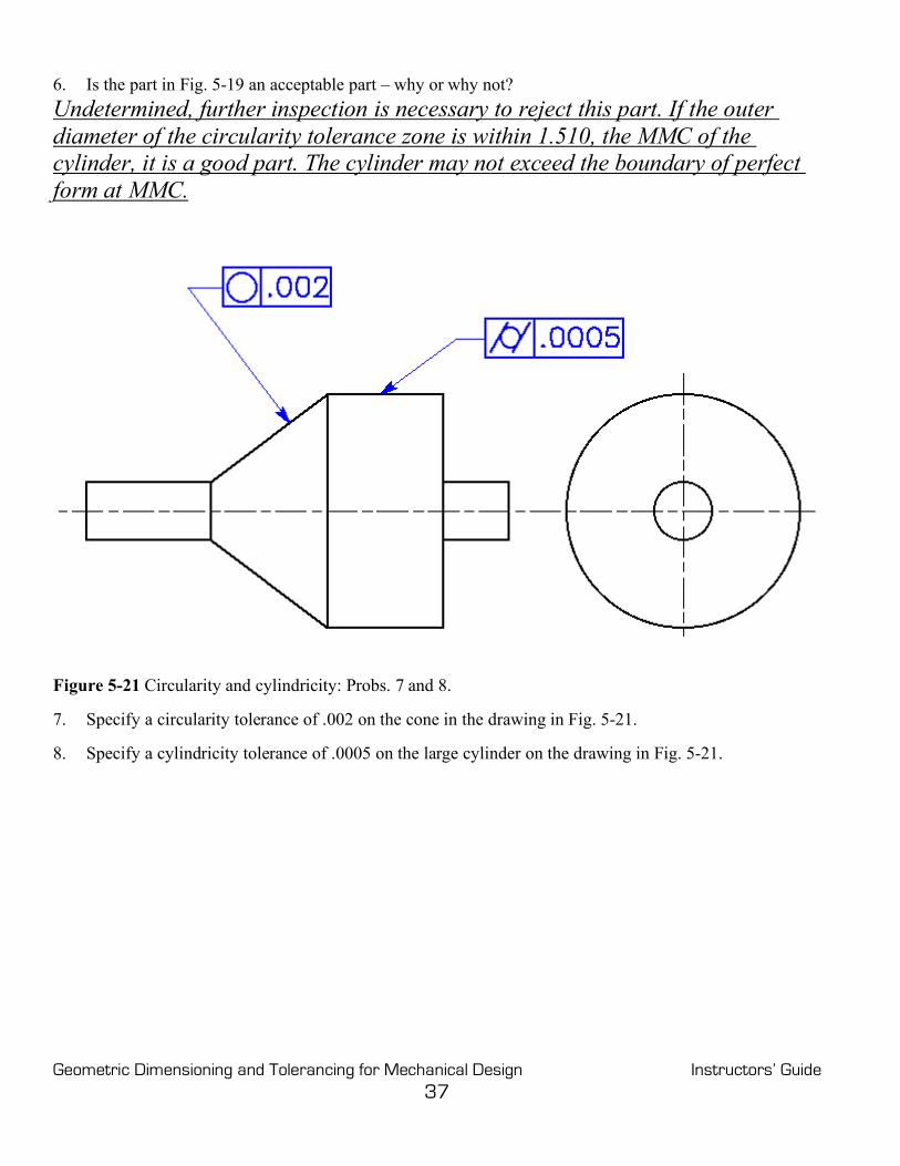
Geometric Dimensioning and Tolerancing for Mechanical Design Instructors’ Guide 37
6. Is the part in Fig. 5-19 an acceptable part – why or why not? Undetermined, further inspection is necessary to reject this part. If the outer diameter of the circularity tolerance zone is within 1.510, the MMC of the cylinder, it is a good part. The cylinder may not exceed the boundary of perfect form at MMC.
Figure 5-21 Circularity and cylindricity: Probs. 7 and 8. 7. Specify a circularity tolerance of .002 on the cone in the drawing in Fig. 5-21. 8. Specify a cylindricity tolerance of .0005 on the large cylinder on the drawing in Fig. 5-21.
Geometric Dimensioning and Tolerancing for Mechanical Design Instructors’ Guide 38
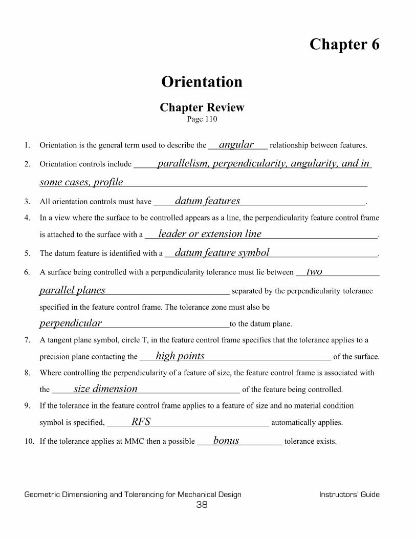
Chapter 6
Orientation Chapter Review
Page 110
1. Orientation is the general term used to describe the angular relationship between features.
2. Orientation controls include parallelism, perpendicularity, angularity, and in
some cases, profile
3. All orientation controls must have datum features .
4. In a view where the surface to be controlled appears as a line, the perpendicularity feature control frame
is attached to the surface with a leader or extension line .
5. The datum feature is identified with a datum feature symbol .
6. A surface being controlled with a perpendicularity tolerance must lie between two
parallel planes separated by the perpendicularity tolerance
specified in the feature control frame. The tolerance zone must also be
perpendicular to the datum plane.
7. A tangent plane symbol, circle T, in the feature control frame specifies that the tolerance applies to a
precision plane contacting the high points of the surface.
8. Where controlling the perpendicularity of a feature of size, the feature control frame is associated with
the size dimension of the feature being controlled.
9. If the tolerance in the feature control frame applies to a feature of size and no material condition
symbol is specified, RFS automatically applies.
10. If the tolerance applies at MMC then a possible bonus tolerance exists.

Geometric Dimensioning and Tolerancing for Mechanical Design Instructors’ Guide 39
Figure 6-14 Specifying perpendicularity of a plane surface: Question 11. 11. Supply the appropriate geometric tolerance on the drawing in Fig. 6-14 to control the 3.00-inch vertical
surface of the part perpendicular to the bottom surface within .005.
Figure 6-15 Specifying perpendicularity of a feature of size: Question 12.

Geometric Dimensioning and Tolerancing for Mechanical Design Instructors’ Guide 40
12. Supply the appropriate geometric tolerance on the drawing in Fig. 6-15 to control the 1.00-inch diameter vertical pin perpendicular to the bottom surface of the plate within .005 at RFS.
Figure 6-16 Perpendicularity specified at MMC: Question 13.
13. If the pin in Fig. 6-15 were produced at a diameter of 1.004 and toleranced with the feature control
frame in Fig. 6-16, what would the total perpendicularity tolerance be? .008
14. The feature control frame contains a parallelism symbol, a numerical tolerance, and at least one datum feature .
15. Parallelism tolerance of a flat surface is a refinement of the size tolerance and must be less than the size tolerance .
16. A surface being controlled with a parallelism tolerance must lie between
two parallel planes separated by the parallelism tolerance specified in the feature control frame. The tolerance zone must also be
parallel to the datum feature.
17. The controlled surface may not exceed the boundary of perfect form at MMC
18. Where applied to a flat surface, parallelism is the only orientation control that requires perfect orientation (Parallelism is a 0° angle.) at MMC .
Figure 6-17 Specifying parallelism: Question 19.
Geometric Dimensioning and Tolerancing for Mechanical Design Instructors’ Guide 41
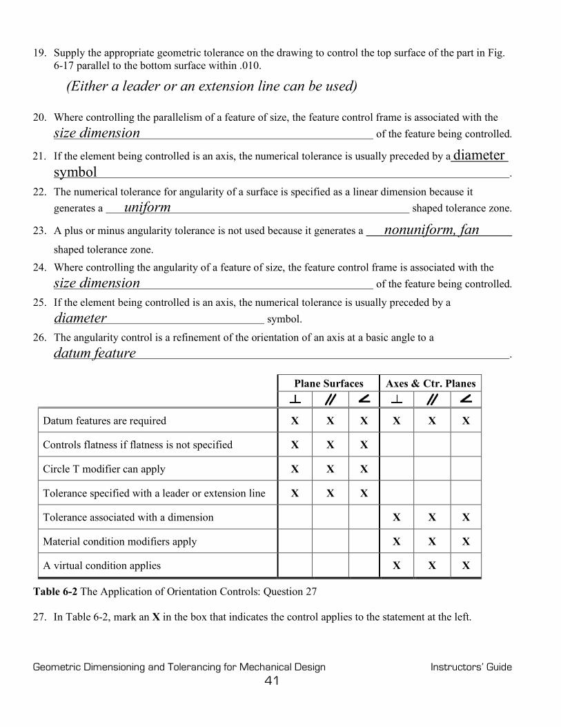
19. Supply the appropriate geometric tolerance on the drawing to control the top surface of the part in Fig. 6-17 parallel to the bottom surface within .010.
(Either a leader or an extension line can be used)
20. Where controlling the parallelism of a feature of size, the feature control frame is associated with the size dimension of the feature being controlled.
21. If the element being controlled is an axis, the numerical tolerance is usually preceded by a diameter symbol .
22. The numerical tolerance for angularity of a surface is specified as a linear dimension because it generates a uniform shaped tolerance zone.
23. A plus or minus angularity tolerance is not used because it generates a nonuniform, fan
shaped tolerance zone. 24. Where controlling the angularity of a feature of size, the feature control frame is associated with the
size dimension of the feature being controlled.
25. If the element being controlled is an axis, the numerical tolerance is usually preceded by a diameter symbol.
26. The angularity control is a refinement of the orientation of an axis at a basic angle to a datum feature .
Plane Surfaces Axes & Ctr. Planes
Datum features are required X X X X X X
Controls flatness if flatness is not specified X X X
Circle T modifier can apply X X X
Tolerance specified with a leader or extension line X X X
Tolerance associated with a dimension X X X
Material condition modifiers apply X X X
A virtual condition applies X X X
Table 6-2 The Application of Orientation Controls: Question 27
27. In Table 6-2, mark an X in the box that indicates the control applies to the statement at the left.

Geometric Dimensioning and Tolerancing for Mechanical Design Instructors’ Guide 42
Problems Page 114
Figure 6-18 Perpendicularity of a plane surface: Probs.1 and 2. 1. Specify the 3.00-inch surface of the part in Fig. 6-18 to be perpendicular to the bottom and back surfaces
within a tolerance of .010. Draw and dimension the tolerance zone. 2. Specify a feature control frame that would require a precision plane surface placed against the 3.00-inch
surface of the part in Fig. 6-18 to be perpendicular to the bottom and back surfaces within a tolerance of .010.
j].010t]A]B]

Geometric Dimensioning and Tolerancing for Mechanical Design Instructors’ Guide 43
Figure 6-19 Perpendicularity of a pin to a plane surface: Prob. 3. 3. Specify the one-inch diameter pin perpendicular to the top surface of the horizontal plate in Fig. 6-19
within a tolerance of .015 at MMC. On the drawing, sketch and dimension a gage used to inspect this part.

Geometric Dimensioning and Tolerancing for Mechanical Design Instructors’ Guide 44
Figure 6-20 Perpendicularity of a cylinder to a plane surface: Prob. 4. 4. Specify the Ø4.000 cylinder perpendicular to its back surface, datum feature A, within a tolerance of .010
at MMC in Fig. 6-20.

Geometric Dimensioning and Tolerancing for Mechanical Design Instructors’ Guide 45
Figure 6-21 Parallelism of a plane surface: Prob. 5. 5. Specify the top surface of the part in Fig. 6-21 parallel to the bottom surface within a tolerance of .004.
Draw and dimension the tolerance zone.

Geometric Dimensioning and Tolerancing for Mechanical Design Instructors’ Guide 46
Figure 6-22 Parallelism of a cylindrical feature of size: Prob. 6. 6. Specify the hole in the part in Fig. 6-22 parallel to datum features B and C within a tolerance of .002 at
MMC.

Geometric Dimensioning and Tolerancing for Mechanical Design Instructors’ Guide 47
Figure 6-23 Perpendicularity of a noncylindrical feature of size: Prob. 7. 7. For the slot in Fig. 6-23, refine the perpendicularity to datum feature A within a tolerance of .002 at
MMC.

Geometric Dimensioning and Tolerancing for Mechanical Design Instructors’ Guide 48
Figure 6-24 Angularity of a plane surface: Prob. 8. 8. Specify the top surface of the part in Fig. 6-24 to be at an angle of 20° to the bottom surface within a
tolerance of .003. Draw and dimension the tolerance zone.
Figure 6-25 Angularity of a feature of size: Prob. 9. 9. For the pin in Fig. 6-25, refine the angularity to datum feature A and parallelism to datum feature B within
a tolerance of .002 at MMC.

Geometric Dimensioning and Tolerancing for Mechanical Design Instructors’ Guide 49
MMC .990 1.015
Geometric Tolerance +.010 –.015
Virtual Condition 1.000 1.000
Figure 6-26 Orientation: problem 10 10. Complete the feature control frames in Fig. 6-26 so that the two parts will always assemble, datum
features A and B will meet, and the part can be produced using the most cost-effective design. The pin is machined in a lathe and the hole is drilled.
(There are several possible solutions to this problem. The virtual conditions should be
equal to insure assembly and to provide maximum tolerance. Typically, for this method of
manufacturing, more tolerance is given to the hole.)

Geometric Dimensioning and Tolerancing for Mechanical Design Instructors’ Guide 50
Chapter 7
Position, General Chapter Review
Page 139
1. Position is a composite tolerance that controls both the location and the orientation
of features of size at the same time.
2. The tolerance of position may be viewed in either of two ways:
• A theoretical tolerance zone located at true position of the toleranced
feature within which the center point, axis, or center plane of the feature
may vary from true position .
• A virtual condition boundary of the toleranced feature, when specified at
MMC or LMC and located at true position, which may not be violated by
its surface or surfaces .
3. A feature of size has four geometric characteristics that must be controlled. These characteristics are
size, form, orientation, and location .
4. Since the position tolerance controls only features of sizes such as pins, holes, tabs, and slots, the
feature control frame is always associated with a size dimension .
5. The location of true position, the theoretically perfect location of an axis, is specified with
basic dimensions from the datum features indicated.
6. Once the feature control frame is assigned, an imaginary tolerance zone is defined
and located about true position.
7. Datum features are identified with datum feature symbols .
8. Datum features A, B, and C identify a datum reference frame ;
consequently, they describe how the part is to be positioned for processing .

Geometric Dimensioning and Tolerancing for Mechanical Design Instructors’ Guide 51
9. If no material condition modifier is specified in the feature control frame, the RFS modifier
automatically applies to the tolerance of the feature.
10. To inspect a hole, the largest pin gage to fit inside the hole is used to simulate the
actual mating envelope .
11. The measurement from the surface plate to the top edge of the pin gage minus half of the diameter of
the pin gage equals the distance from datum feature B to the actual axis of the hole.
12. Where the maximum material condition symbol is specified to modify the tolerance of a feature of size,
the following two requirements apply:
• The specified tolerance applies at the maximum material condition of the feature.
• As the size of the feature departs from MMC toward LMC, a bonus tolerance is achieved .
13. The difference between the actual mating envelope size and the MMC is the bonus.
14. The bonus plus the geometric tolerance equals the total positional tolerance .
Figure 7-19 Geometric tolerance: Questions 15 through 18.
15. If the tolerance in Fig.7-19 is for a pin .525 in diameter, what is the total positional tolerance? .035
16. What would be the size of the hole in a functional gage to inspect the pin above? .560
17. If the tolerance in Fig. 7-19 is for a hole .540 in diameter, what is the total positional tolerance? .040
18. What would be the size of the pin on a functional gage to inspect the hole above? .500
19. Where a datum feature of size is toleranced with a geometric tolerance and is referenced in a feature
control frame at MMB, the resulting maximum material boundary for the feature is equal to
its virtual condition with respect to the preceding datum feature.
20. A zero tolerance is not used where the tolerance applies at RFS ,
or where no bonus tolerance is available as in a tolerance specified for threads or press fit pins.

Geometric Dimensioning and Tolerancing for Mechanical Design Instructors’ Guide 52
Problems Page 142
Figure 7-20 Locating a hole with the position control: Probs. 1 through 3. 1. Locate the hole in Fig. 7-20 with a positional tolerance of .005 at RFS. 2. Draw a feature control frame below to locate the hole in Fig. 7-20 with a positional tolerance of .005 at
MMC.
n]w.005m]A]B]C] 3. If the actual mating envelope in the hole in problem 2 is produced at a diameter of 2.010 and the axis is
located .003 over and .005 up from true position, is the part within tolerance? If not, can it be reworked to meet specifications?
Bonus = AME – MMC = 2.010 – 2.005 = .005 The Total Positional Tolerance = Geometric Tolerance + Bonus = .005 +.005 = .010 The distance from the axis to true position = the square root of (.003)2 + (.005)2 = .006. This distance from the axis to true position requires a cylindrical tolerance zone Ø.012. The part is not in tolerance. If the size of the hole is increased by at least .002, it would be in tolerance.

Geometric Dimensioning and Tolerancing for Mechanical Design Instructors’ Guide 53
Figure 7-21 Locating features to a datum feature of size: Probs. 4 through 6. 4. Position the four-hole pattern with a tolerance of .010 at MMC in Fig. 7-21 perpendicular to datum
feature A and located to datum feature B at RMB. If datum feature B is produced at a diameter of 4.010, how much shift tolerance is available?
None, datum feature is specified at RMB. 5. Draw a feature control frame below to position the four-hole pattern in Fig. 7-21 perpendicular to
datum feature A and located to datum feature B at MMB.
n]w.010m]A]Bm] 6. How much shift tolerance is available in Fig. 7-21 if datum feature B is specified at MMB and is
produced at 4.015 in diameter? MMB = 4.030, 4.030 – 4.015 = .015 Shift Tolerance

Geometric Dimensioning and Tolerancing for Mechanical Design Instructors’ Guide 54
Figure 7-22 Design a gage to inspect for shift tolerance: Probs. 7 and 8. 7. On a gage designed to control the 4-hole pattern in Fig. 7-22, what size pin must be produced to
inspect the center hole (datum feature D)? Ø1.000
8. On the same gage, what is the diameter of the four pins locating the hole pattern? Ø.500

Geometric Dimensioning and Tolerancing for Mechanical Design Instructors’ Guide 55
Figure 7-23 A pattern of holes located to a datum feature of size: Prob. 9. 9. In Fig. 7-23, locate the 1¼-inch-diameter hole to the edge datum features within a tolerance of .060 and
refine its perpendicularity to datum feature A with a tolerance of .010. Locate the nine-hole pattern to the 1¼-inch-diameter hole and clock it to an edge datum feature with a zero positional tolerance. Use MMC and MMB wherever possible.

Geometric Dimensioning and Tolerancing for Mechanical Design Instructors’ Guide 56
Figure 7-24 A hole specified at LMC: Prob. 10. 10. Calculate the minimum wall thickness between the inside diameter and datum feature B shown in Fig.
7-24.
Datum B @ LMC Ø 2.480
I. D. @ LMC – Ø 2.020
Tolerance @ LMC – Ø .020
.440
The wall thickness equals half of the differences in diameters or .220.
(Calculating diameters and diving the final diameter in half minimize Errors.)

Geometric Dimensioning and Tolerancing for Mechanical Design Instructors’ Guide 57
Figure 7-25 Boundary conditions: Prob. 11. 11. First calculate the virtual conditions and resultant conditions for the pin and hole in Fig.7-25. Then
calculate the maximum and minimum distances for dimensions X and Y. The Virtual Condition of the PIN. The Virtual Condition of the HOLE.
VCp = MMC + Geo. Tol. VCh = MMC – Geo. Tol. VCp = 1.000 + .004 = 1.004 VCh = 1.000 – .004 = .996 VCp/2 = .502 VCh/2 =.498 Resultant Condition of the PIN. Resultant Condition of the HOLE.
RCp = LMC – Geo. Tol. – Bonus RCh = LMC + Geo. Tol. + Bonus RCp =.998 – .004 – .002 = .992 RCh =1.006 +.004 +.006 =1.016 RCp/2 = .496 RCh/2 =.508 The maximum and minimum distances for dimension X:
XMax = Dist. – RCp/2 – VCh/2 = XMin = Dist. VCp /2 – RCh /2 = XMax =3.000 – .496 – .498 = XMin = 3.000 – .502 – .508 XMax = 2.006 XMin =1.990

Geometric Dimensioning and Tolerancing for Mechanical Design Instructors’ Guide 58
The maximum and minimum distances for dimension Y:
YMax =Length @ MMC – Dist. – VCh/2 = YMin = Length @ LMC – Dist – RCh/2 = YMax =6.010 – 4.500 –.498 = YMin = 5.990 – 4.500 – .508 = YMax =1.012 YMin =.982
Figure 7-26 Zero positional tolerance conversion: Probs. 12 and 13
12. Convert the tolerance in Fig. 7-26 to zero positional tolerances.
13. Zero tolerance is not used when the tolerance applies at RFS , or when no bonus tolerance is available as in a tolerance specified for
threads or press fit pins.
Chapter 8
Position, Location Chapter Review
Page 176
1. The floating fastener formula is:
T = H – F or H = F + T
2. T = Tol. at MMC H = Hole Ø at MMC F = Fastener Ø at MMC
3. The clearance hole LMC diameter formula is H @ LMC = (F +F head) / 2 .

Geometric Dimensioning and Tolerancing for Mechanical Design Instructors’ Guide 59
4. The fixed fastener is fixed by one or more of the members being fastened .
5. The formula for fixed fasteners is:
t1 + t2 = H – F or H = F + t1 + t2 6. The formula for fixed fasteners is essentially the same as for floating fasteners except that the fixed
fastener formula includes the tolerance for each hole.
7. It is common practice to assign a larger portion of the location tolerance to the threaded hole.
8. A fastener fixed at its head in a countersunk hole and in a threaded hole at the other end is called what? A double fixed fastener
9. Where specifying a threaded hole or a hole for a press fit pin, the orientation of the
hole determines the orientation of the mating pin.
10. The most convenient way to control the orientation of a pin outside the hole is to
project the tolerance zone into the mating part.
11. The height of the projected tolerance zone is equal to or greater than the thickest mating
part or tallest stud or pin after installation.
12. Two or more patterns of features are considered to be a single pattern of features if they are:
located with basic dimensions, to the same datums features, in the same
order of precedence, and at the same material conditions
13. Datum features of size specified at RMB require physical contact
between the gagging element and the datum feature.
14. If patterns of features controlled to datum features of size specified at MMB have no relationship to
each other, a note such as SEP REQT may be placed
under each feature control frame allowing each pattern to be inspected separately.
15. When locating patterns of features, there are situations where the relationship from
feature to feature must be kept to a certain tight tolerance and the relationship between
the pattern and its datum features is not as critical and may be held to a looser
tolerance.
16. A composite feature control frame has one position symbol

Geometric Dimensioning and Tolerancing for Mechanical Design Instructors’ Guide 60
that applies to the two horizontal segments that follow.
17. The upper segment of a composite feature control frame is called the pattern-locating
control, it governs the relationship between the datum features and the pattern .
18. The lower segment of a composite feature control frame is called the feature-relating
control; it governs the relationship from feature to feature
19. The primary function of the position control is to control location
20. Datum features in the lower segment of a composite feature control frame must satisfy what two
conditions? They are required to repeat the datums in the upper segment
They only control orientation
(Assume plane surface datum features for Questions 21 and 23)
21. Where the secondary datum feature is included in the lower segment of a composite feature control
frame, the tolerance zone framework must remain Parallel to the secondary datum plane.
22. The lower segment of a multiple single-segment feature control frame acts just like any other
position control . 23. Counterbores that have the same location tolerance as their respective holes are specified by indicating
the hole callout and the counterbore callout followed by the geometric
tolerance for both
24. Counterbores that have a larger location tolerance than their respective holes are specified by
separating the hole callout from the counterbore callout .
25. When tolerancing elongated holes, no diameter symbol precedes
the tolerance in the feature control frame since the tolerance zone is not cylindrical .
26. The virtual condition boundary is the exact shape of
the noncircular feature and equal in size to its virtual condition .
27. The position control is used to locate a feature of size symmetrically at MMC to a
datum feature of size specified at MMB.

Geometric Dimensioning and Tolerancing for Mechanical Design Instructors’ Guide 61
Problems Page 179
Figure 8-28 Floating fastener tolerance: Prob. 1. 1. Tolerance the clearance holes on the plate in Fig. 8-28 to be fastened with 5/16 – 18 UNC hex head
bolts (.313 in diameter) and nuts with a .010-diameter positional tolerance at MMC.

Geometric Dimensioning and Tolerancing for Mechanical Design Instructors’ Guide 62
Fig. 8-29 Floating fastener tolerance at MMC: Probs. 2 through 5.
2. Specify the MMC and LMC clearance hole sizes for #10 (Ø.190) socket head cap screws.
(Many other solutions are possible, but they must satisfy the floating fastener formula.)
2X Ø.220-.246 2X Ø.200-.246 2X Ø.190-.246 n]w.030m]A]B]C] n]w.010m]A]B]C] n]w.000m]A]B]C] 3. If the actual mating envelope size of the clearance holes in problem 2 are .230 in diameter, calculate the
total positional tolerance for each callout. Actual Size .230 .230 .230
MMC – .220 – .200 – .190
Bonus .010 .030 .040
Geo. Tolerance + .030 + .010 + .000
Total Tolerance .040 .040 .040 4. Specify the MMC and LMC clearance hole sizes for 3/8 (Ø.375) hex head bolts.
2X Ø .400-.460 2X Ø .390-.460 2X Ø .375-.460 n]w.025m]A]B]C] n]w.015m]A]B]C] n]w.000m]A]B]C]

Geometric Dimensioning and Tolerancing for Mechanical Design Instructors’ Guide 63
5. If the actual mating envelope size of the clearance holes in Prob. 4 measure .440 in diameter, calculate the total positional tolerance for each callout.
Actual Size .440 .440 .440
MMC – .400 – .390 – .375
Bonus .040 .050 .065
Geo. Tolerance + .025 + .015 + .000
Total Tolerance .065 .065 .065
Figure 8-30 Fixed fastener tolerance: Prob. 6. 6. Tolerance the clearance and threaded holes in the plates in Fig. 8-30 to be fastened with 5/8–11 UNC
hex head bolts (.625 in diameter). Use a .000 positional tolerance at MMC wherever possible, and calculate a 60% location tolerance for the threaded holes.
Geometric Dimensioning and Tolerancing for Mechanical Design Instructors’ Guide 64
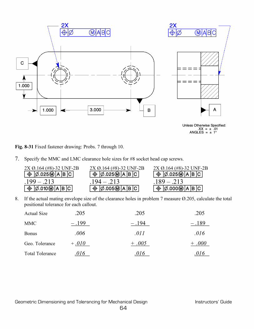
Fig. 8-31 Fixed fastener drawing: Probs. 7 through 10.
7. Specify the MMC and LMC clearance hole sizes for #8 socket head cap screws.
2X Ø.164 (#8)-32 UNF-2B 2X Ø.164 (#8)-32 UNF-2B 2X Ø.164 (#8)-32 UNF-2B n]w.025m]A]B]C] n]w.025m]A]B]C] n]w.025m]A]B]C] .199 – .213 .194 – .213 .189 – .213 n]w.010m]A]B]C] n]w.005m]A]B]C] n]w.000m]A]B]C] 8. If the actual mating envelope size of the clearance holes in problem 7 measure Ø.205, calculate the total
positional tolerance for each callout.
Actual Size .205 .205 .205
MMC – .199 – .194 – .189
Bonus .006 .011 .016
Geo. Tolerance + .010 + .005 + .000
Total Tolerance .016 .016 .016

Geometric Dimensioning and Tolerancing for Mechanical Design Instructors’ Guide 65
9. Specify the MMC and LMC clearance hole sizes for the ½ inch hex head bolts.
2X Ø .500-20 UNF-2B 2X Ø .500-20 UNF-2B 2X Ø .500-20 UNF-2B n]w.060m]A]B]C] n]w.060m]A]B]C] n]w.060m]A]B]C]
2X Ø.580 – .612 2X Ø.570 – .612 2X Ø.560 – .612 n]w.020m]A]B]C] n]w.010m]A]B]C] n]w.000m]A]B]C]
10. If the actual mating envelope size of the clearance holes in problem 9 measure Ø.585, calculate the total positional tolerance for each callout.
Actual Size .585 .585 .585
MMC – .580 – .570 – .560
Bonus .005 .015 .025
Geo. Tolerance + .020 + .010 + .000
Total Tolerance .025 .025 .025

Geometric Dimensioning and Tolerancing for Mechanical Design Instructors’ Guide 66
Figure 8-32 Projected tolerance zone: Prob. 11. 11. Complete the drawing in Fig. 8-32. Specify a .040 positional tolerance at MMC with the appropriate
projected tolerance.

Geometric Dimensioning and Tolerancing for Mechanical Design Instructors’ Guide 67
Figure 8-33 Projected tolerance zone for studs: Prob. 12. 12. Complete the drawing in Fig. 8-33. Specify a .050 positional tolerance at MMC with the appropriate
projected tolerance.

Geometric Dimensioning and Tolerancing for Mechanical Design Instructors’ Guide 68
Figure 8-34 Fixed fastener assembly: Prob. 13. 13. The part with clearance holes in Fig. 8-34 assembles on top of the part with threaded holes and is
fastened with cap screws. Allow a tolerance of at least .030 on both threaded and clearance holes, use "0" positional tolerance at MMC, and specify projected tolerance zones.
Geometric Dimensioning and Tolerancing for Mechanical Design Instructors’ Guide 69
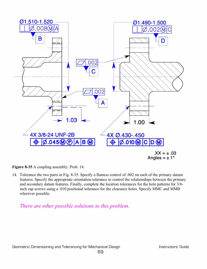
Figure 8-35 A coupling assembly: Prob. 14. 14. Tolerance the two parts in Fig. 8-35. Specify a flatness control of .002 on each of the primary datum
features. Specify the appropriate orientation tolerance to control the relationships between the primary and secondary datum features. Finally, complete the location tolerances for the hole patterns for 3/8-inch cap screws using a .010 positional tolerance for the clearance holes. Specify MMC and MMB wherever possible.
There are other possible solutions to this problem.

Geometric Dimensioning and Tolerancing for Mechanical Design Instructors’ Guide 70
Figure 8-36 A pattern of holes located to a datum feature of size: Prob. 15. 15. In Fig. 8-36, the inside diameter and the back are mating features. Select the primary datum
feature. (Consider a form control.) The virtual condition of the mating shaft is 1.125 in diameter. Locate the keyway for a ¼-inch key. Locate the three-hole pattern for 7/16-inch (Ø.438) cap screws as floating fasteners with a zero positional tolerance at MMC. Specify MMC and MMB wherever possible.

Geometric Dimensioning and Tolerancing for Mechanical Design Instructors’ Guide 71
Figure 8-37 Multiple patterns of features: Probs. 16 through 18. 16. In Fig. 8-37, position the small holes with .000 tolerance at MMC and the large holes with .010
tolerance at MMC; locate them to the same datum features and in the same order of precedence. Use MMC and MMB wherever possible.
17. Must the hole patterns be inspected in the same setup or in the same gage? Explain?
Yes, they must be inspected to the same datum features. The large hole and
small hole patterns are tied together by their datums features. 18. Can the requirement be changed, how?
Yes, place a note, SEPT REQT, under each feature control frame.

Geometric Dimensioning and Tolerancing for Mechanical Design Instructors’ Guide 72
Figure 8-38 Composite positional tolerancing: Probs. 19 and 20. 19. Locate the pattern of clearance holes on the part in Fig. 8-38 with a tolerance of at least .060 in
diameter at MMC to the datum features specified. This plate is required to assemble to the mating part with ¼-inch hex bolts as floating fasteners. Complete the geometric tolerance.
20. It has been determined that the hole pattern in Fig. 8-38 is required to remain parallel to datum feature
B within the smaller tolerance. Draw the feature control frame that will satisfy this requirement.

Geometric Dimensioning and Tolerancing for Mechanical Design Instructors’ Guide 73
Figure 8-39 Composite positional tolerancing of holes with different sizes: Prob. 21. 21. Locate all five holes in Fig. 8-39 within a tolerance of .060 to the datum features specified. Also, locate
all five holes to each other and perpendicular to datum feature A within a positional tolerance of .010. Use MMC and MMB wherever applicable.

Geometric Dimensioning and Tolerancing for Mechanical Design Instructors’ Guide 74
Figure 8-40 Composite positional tolerancing locating a radial hole pattern: Prob. 22. 22. Locate the ¼ inch keyway to datum features A and B on Fig. 8-40. Position the four-hole pattern within
a tolerance of .020 to datum features A, B, and C. Refine the orientation of the four-hole pattern parallel to datum feature A, perpendicular to datum feature B at MMB, and parallel and perpendicular to the center plane of the keyseat within zero tolerance at MMC.

Geometric Dimensioning and Tolerancing for Mechanical Design Instructors’ Guide 75
Figure 8-41 Multiple single-segment positional tolerancing to control holes: Prob. 23. 23. The inner and outer shafts in Fig. 8-41 will assemble every time. Control the location of the clearance
holes for a ½ inch fastener with a multiple single-segment positional tolerance. Locate the holes to the end of each shaft with a tolerance of .040 Locate the holes to the axis of each shaft using the floating fastener formula. Specify MMC and MMB wherever possible.

Geometric Dimensioning and Tolerancing for Mechanical Design Instructors’ Guide 76
Figure 8-42 Controlling counterbores with positional tolerancing: Probs. 24 and 25. 24. Tolerance the holes and counterbores in Fig. 8-42 for four ¼-inch socket head cap screws. The cap
screw head is a diameter of .365-.375, the height is .244-.250. Specify MMC and MMB wherever possible.
25. If the geometric tolerance for just the counterbores in Fig. 8-42 can be loosened to .020 at MMC
instead of .010, draw the entire callout below.
4X Ø.260-.290 n]w.010m]A]B]C] 4X $ Ø.395-.405 ^ .250-.270 n]w.020m]A]B]C]

Geometric Dimensioning and Tolerancing for Mechanical Design Instructors’ Guide 77
Figure 8-43 Controlling noncircular features with positional tolerancing: Prob. 26. 26. In Fig. 8-43, specify a geometric tolerance of .040 at MMC for the 1/2-inch direction and .060 at MMC
for the 1-inch direction for the noncircular features.

Geometric Dimensioning and Tolerancing for Mechanical Design Instructors’ Guide 78
Figure 8-44 Controlling symmetrical features with positional tolerancing: Prob. 27. 27. In Fig. 8-44, control the symmetry of the 2-inch feature with respect to the 4-inch feature and
perpendicular to datum feature A within a tolerance of .020. Use MMC and MMB wherever possible. 28. If the controlled feature in Fig. 8-44 happened to be produced at 1.995 and the datum feature produced
at 4.000, what would be the total positional tolerance? .027
Geometric Dimensioning and Tolerancing for Mechanical Design Instructors’ Guide 79
Chapter 9
Position, Coaxiality Chapter Review
Page 204
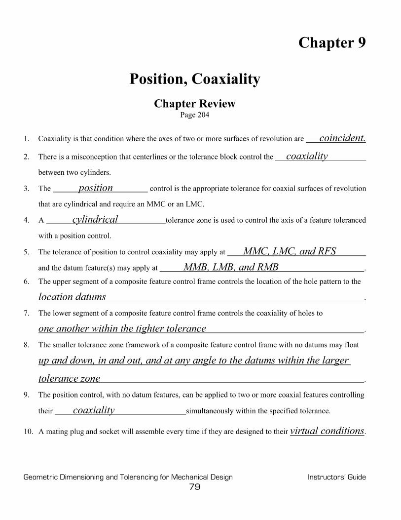
1. Coaxiality is that condition where the axes of two or more surfaces of revolution are coincident.
2. There is a misconception that centerlines or the tolerance block control the coaxiality
between two cylinders.
3. The position control is the appropriate tolerance for coaxial surfaces of revolution
that are cylindrical and require an MMC or an LMC.
4. A cylindrical tolerance zone is used to control the axis of a feature toleranced
with a position control.
5. The tolerance of position to control coaxiality may apply at MMC, LMC, and RFS
and the datum feature(s) may apply at MMB, LMB, and RMB .
6. The upper segment of a composite feature control frame controls the location of the hole pattern to the
location datums .
7. The lower segment of a composite feature control frame controls the coaxiality of holes to
one another within the tighter tolerance .
8. The smaller tolerance zone framework of a composite feature control frame with no datums may float
up and down, in and out, and at any angle to the datums within the larger
tolerance zone .
9. The position control, with no datum features, can be applied to two or more coaxial features controlling
their coaxiality simultaneously within the specified tolerance.
10. A mating plug and socket will assemble every time if they are designed to their virtual conditions.

Geometric Dimensioning and Tolerancing for Mechanical Design Instructors’ Guide 80
Problems Page 205
Figure 9-9 Controlling coaxiality with positional tolerancing: Probs. 1 through 3. 1. What controls the coaxiality of the two cylinders on the drawing in Fig. 9-9? The way the drawing in Fig. 9-7 is shown, nothing controls coaxiality. 2. On the drawing in Fig. 9-9, specify a coaxiality tolerance to control the 1.000 diameter feature within a
cylindrical tolerance zone of .004 to the 2.00-diameter feature. Use MMC and MMB wherever possible.
3. Now that the feature control frame has been added to the drawing in Fig. 9-9, if the larger diameter is
produced at 2.00 inches and the smaller diameter is produced at 1.000 inch, how much total coaxiality tolerance applies?
Ø .019

Geometric Dimensioning and Tolerancing for Mechanical Design Instructors’ Guide 81
Figure 9-10 Controlling coaxiality with composite positional tolerancing: Prob. 4. 4. Locate the two holes in the hinge brackets within .030 at MMC to the datum features indicated and
specify coaxiality to each other. They must be able to accept a .500 diameter hinge pin. Specify MMC and MMB wherever possible.

Geometric Dimensioning and Tolerancing for Mechanical Design Instructors’ Guide 82
Figure 9-11 Controlling two coaxial holes and mating pin of different diameters: Prob. 5. 5. Locate the two coaxial holes parallel to the back and bottom surfaces of the part within a tolerance of
.040 at MMC. Use the appropriate tolerance to control the coaxiality for the two mating parts. Specify MMC and MMB wherever possible.

Geometric Dimensioning and Tolerancing for Mechanical Design Instructors’ Guide 83
Figure 9-12 Controlling coaxiality with positional tolerancing without datum features: Prob. 6. 6. Control the three, 3-inch diameters coaxial to each other with a tolerance of .010 at MMC using the
position control without datum features.
Figure 9-13 Controlling coaxiality for a plug and socket: Prob. 7. 7. Control the coaxiality of both parts in Fig. 9-13 so that they will always assemble. Specify MMC and
MMB wherever possible.
Geometric Dimensioning and Tolerancing for Mechanical Design Instructors’ Guide 84
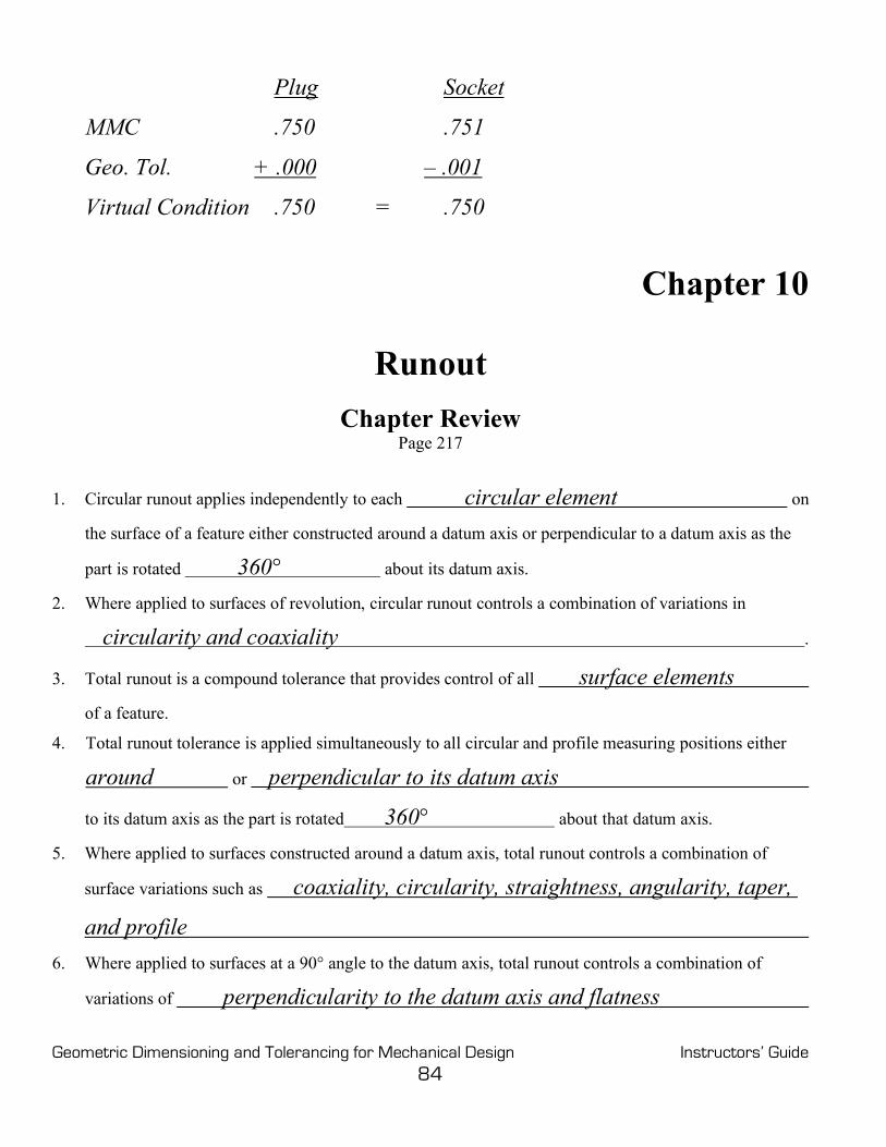
Plug Socket
MMC .750 .751
Geo. Tol. + .000 – .001
Virtual Condition .750 = .750
Chapter 10
Runout Chapter Review
Page 217
1. Circular runout applies independently to each circular element on
the surface of a feature either constructed around a datum axis or perpendicular to a datum axis as the
part is rotated 360° about its datum axis.
2. Where applied to surfaces of revolution, circular runout controls a combination of variations in
circularity and coaxiality .
3. Total runout is a compound tolerance that provides control of all surface elements
of a feature.
4. Total runout tolerance is applied simultaneously to all circular and profile measuring positions either around or perpendicular to its datum axis
to its datum axis as the part is rotated 360° about that datum axis.
5. Where applied to surfaces constructed around a datum axis, total runout controls a combination of
surface variations such as coaxiality, circularity, straightness, angularity, taper,
and profile
6. Where applied to surfaces at a 90° angle to the datum axis, total runout controls a combination of
variations of perpendicularity to the datum axis and flatness

Geometric Dimensioning and Tolerancing for Mechanical Design Instructors’ Guide 85
7. The runout feature control frame consists of a runout symbol, the numerical
tolerance, and at least one datum feature .
8. In many cases, two functional datum features are used to support a rotating part.
9. The planar and cylindrical datum reference frame is quite a different requirement than the
common datum reference frame.
10. Design requirements may make it necessary to restrict datum surface variations with respect to (other
geometric controls) straightness, flatness, circularity, cylindricity, and
parallelism.
11. It may be necessary to include a runout control for individual datum features on a
common datum feature reference.
12. If two or more surfaces are controlled with a runout tolerance to a common datum reference, the worst-
case runout between two surfaces is the sum of the two individual runout tolerances.
13. If two features have a specific relationship between them, one should be toleranced
directly to the other and not through a common datum axis.
14. Multiple leaders directed from a runout feature control frame may be specified without
affecting the runout tolerance.
Problems Page 218
Figure 10-8 Controlling a coaxial feature with a runout control: Prob. 1.
Geometric Dimensioning and Tolerancing for Mechanical Design Instructors’ Guide 86
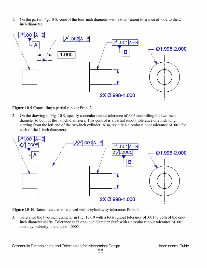
1. On the part in Fig.10-8, control the four-inch diameter with a total runout tolerance of .002 to the 2-inch diameter.
Figure 10-9 Controlling a partial runout: Prob. 2. 2. On the drawing in Fig. 10-9, specify a circular runout tolerance of .002 controlling the two-inch
diameter to both of the 1-inch diameters. This control is a partial runout tolerance one inch long, starting from the left end of the two-inch cylinder. Also, specify a circular runout tolerance of .001 for each of the 1-inch diameters.
Figure 10-10 Datum features toleranced with a cylindricity tolerance: Prob. 3. 3. Tolerance the two-inch diameter in Fig. 10-10 with a total runout tolerance of .001 to both of the one-
inch diameter shafts. Tolerance each one-inch diameter shaft with a circular runout tolerance of .001 and a cylindricity tolerance of .0005.

Geometric Dimensioning and Tolerancing for Mechanical Design Instructors’ Guide 87
Figure 10-11 Multiple features tolerance with one feature control frame: Probs. 4 and 5.
4. In Fig. 10-11, which datum feature, A or B, takes precedence?
Datum feature A is no more important than datum feature B, and datum feature B is no more important than datum feature A.
5. What is the worst possible runout tolerance between datum feature A and datum feature B in Fig. 10-
11? .006
Geometric Dimensioning and Tolerancing for Mechanical Design Instructors’ Guide 88
Chapter 11
Profile Chapter Review
Page 236
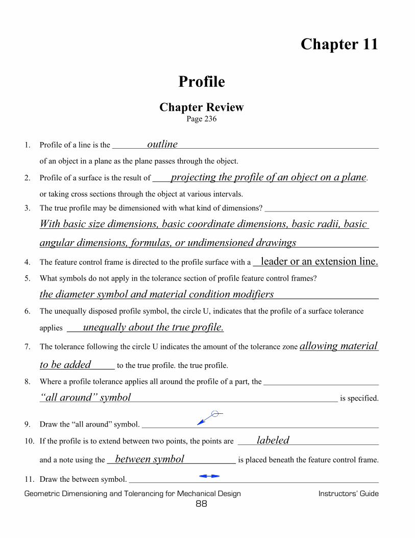
1. Profile of a line is the outline
of an object in a plane as the plane passes through the object.
2. Profile of a surface is the result of projecting the profile of an object on a plane.
or taking cross sections through the object at various intervals.
3. The true profile may be dimensioned with what kind of dimensions?
With basic size dimensions, basic coordinate dimensions, basic radii, basic
angular dimensions, formulas, or undimensioned drawings
4. The feature control frame is directed to the profile surface with a leader or an extension line. 5. What symbols do not apply in the tolerance section of profile feature control frames?
the diameter symbol and material condition modifiers 6. The unequally disposed profile symbol, the circle U, indicates that the profile of a surface tolerance
applies unequally about the true profile.
7. The tolerance following the circle U indicates the amount of the tolerance zone allowing material
to be added to the true profile. the true profile.
8. Where a profile tolerance applies all around the profile of a part, the
“all around” symbol is specified.
9. Draw the “all around” symbol.
10. If the profile is to extend between two points, the points are labeled
and a note using the between symbol is placed beneath the feature control frame.
11. Draw the between symbol.

Geometric Dimensioning and Tolerancing for Mechanical Design Instructors’ Guide 89
12. If a part is to be controlled with a profile tolerance over the entire surface of the part, the
“ALL OVER” symbol is specified.
13. Profile tolerances may or may not have datum features.
14. The profile of a surface control usually requires a datum feature(s) to properly
orient and locate the surface .
15. Datum features are generally not used for profile of a line where
only the cross section is being controlled.
16. If the design requires a smaller radius than the radius allowed by the profile tolerance, a note such as,
“R.015 MAX” or, “ALL CORNERS R.015 MAX,”
is directed to the radius with a leader .
17. The profile tolerance may be combined with other geometric tolerances
to refine certain aspects of a surface.
18. Coplanarity is the condition of two or more
surfaces having all elements in one plane .
19. Coplanarity is toleranced with the profile of a surface feature control frame, connected with a leader , to an extension line connecting the coplanar surfaces.
20. The number of coplanar surfaces followed by an X precedes the feature control frame.
21. A profile tolerance may be used to control two or more stepped surfaces that are
required to be flat and parallel within a specific tolerance.
22. Conicity may be controlled with a profile tolerance .
23. Composite profile tolerancing is very similar to composite positional tolerancing .
24. The upper segment of a composite profile feature control frame called
the profile locating control governs the
location relationship between the datum features and the profile .
25. The lower segment, referred to as the profile refinement control ,
is a smaller tolerance than the profile locating control and governs

Geometric Dimensioning and Tolerancing for Mechanical Design Instructors’ Guide 90
the size, form, and orientation relationship of the profile.
26. The feature profile must fall inside both profile tolerance zones .
27. Datum features in the lower segment of a composite feature control frame must satisfy two conditions:
They must repeat the datums in the upper segment.
And they only control orientation .
28. A second datum feature may be repeated in the lower segment of the composite feature control frame.
Both datum features only control orientation .
29. The lower segment of a multiple single-segment profile feature control frame acts just like
any other profile control .
30. The upper segment of a multiple single-segment profile feature control frame allows the smaller
tolerance zone to translate relative to the datum feature not repeated in the lower segment
within the larger tolerance.
Problems Page 238
Figure 11-18 Controlling the profile of a surface all around: Prob. 1.
1. Specify a profile of a surface tolerance of .020, perpendicular to datum feature A, and all around the part in Fig. 11-18.

Geometric Dimensioning and Tolerancing for Mechanical Design Instructors’ Guide 91
Figure 11-19 Controlling the profile of a surface between two points: Prob. 2. 2. Control the top surface between points X and Y in Fig. 11-19, specify a profile tolerance of .030,
located to datum features A, B, and C.

Geometric Dimensioning and Tolerancing for Mechanical Design Instructors’ Guide 92
Figure 11-20 Control the location of a profile: Prob. 3. 3. Control the entire surface of the die cavity in Fig. 11-20 to the datum features indicated within a
tolerance of .015 in the direction that would remove material from the true profile.

Geometric Dimensioning and Tolerancing for Mechanical Design Instructors’ Guide 93
Figure 11-21 Locating a mating profile: Prob. 4. 3. Control the entire surface of the punch in Fig. 11-21 to the datum features indicated within a tolerance
of .015 in the direction that would remove material from the true profile.

Geometric Dimensioning and Tolerancing for Mechanical Design Instructors’ Guide 94
Figure 11-22 Control a profile with combined tolerances: Prob. 5. 5. Use the profile of a surface control to tolerance the curve in Fig. 11-22 within .030 between points M
and N. Each line element in the profile must be parallel to datum features B and C within .010. The point at M may not exceed a radius of .010.

Geometric Dimensioning and Tolerancing for Mechanical Design Instructors’ Guide 95
Figure 11-23 Controlling coplanarity with the profile of a surface: Prob. 6. 6. The primary datum feature is the two lower coplanar surfaces in Fig. 11-23. Specify the primary datum
feature to be coplanar within .004.

Geometric Dimensioning and Tolerancing for Mechanical Design Instructors’ Guide 96
Figure 11-24 Controlling coplanarity to a datum feature: Prob. 7. 7 Control the bottom three surfaces in Fig. 11-24 coplanar and parallel to datum feature A within .010.
Figure 11-25 Controlling a stepped part with a profile of a surface: Prob. 8. 8. Control the three bottom surfaces in Fig. 11-25 flat, parallel, and stepped one basic inch apart within
.005.
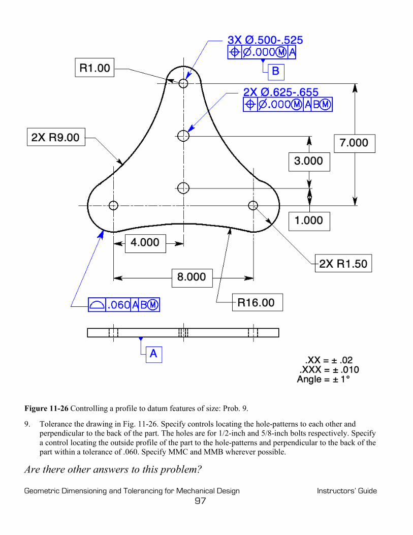
Geometric Dimensioning and Tolerancing for Mechanical Design Instructors’ Guide 97
Figure 11-26 Controlling a profile to datum features of size: Prob. 9. 9. Tolerance the drawing in Fig. 11-26. Specify controls locating the hole-patterns to each other and
perpendicular to the back of the part. The holes are for 1/2-inch and 5/8-inch bolts respectively. Specify a control locating the outside profile of the part to the hole-patterns and perpendicular to the back of the part within a tolerance of .060. Specify MMC and MMB wherever possible.
Are there other answers to this problem?

Geometric Dimensioning and Tolerancing for Mechanical Design Instructors’ Guide 98
Figure 12-27 Composite profile tolerancing: Probs. 10 through 12. 10. In Fig. 11-27, specify a profile tolerance for the center cutout that will control the size, form, and
orientation to datum feature A within .010, and locate the cutout within .060 to the datum features indicated. Complete the drawing.
11. Draw a profile tolerance below that will satisfy the requirements for problem 10 and in addition, orient
the cutout parallel to datum feature B within .010.
12. Draw a profile tolerance below that will satisfy the requirements for problem 10 and in addition, locate the cutout to datum feature B within .010.

Geometric Dimensioning and Tolerancing for Mechanical Design Instructors’ Guide 99
Figure 11-28 Controlling the surface of a sheet metal part with profile: Prob. 13. 13. Specify the lower two surfaces of the bottom of the sheet metal part in Fig. 11-28 coplanar within .020.
Tolerance the holes with geometric tolerancing. The MMC for each hole is the virtual condition for the mating fastener. Specify the profile of the top surface of the sheet metal part within .040. Use MMC and MMB wherever possible.

Geometric Dimensioning and Tolerancing for Mechanical Design Instructors’ Guide 100
Figure 11-29 Controlling the surface of a sheet metal part with profile and datum targets: Prob. 14 9 (p.
246) 14. Tolerance the holes in Fig. 11-29 with geometric tolerancing to datum features A, B, and C. The sizes
of the holes are for ½-inch, ¼-inch, and #10 fastener sizes. Specify the profile of the top surface of the part within a tolerance of .030 to datum features A, B, and C. Use MMC and MMB wherever possible.

Geometric Dimensioning and Tolerancing for Mechanical Design Instructors’ Guide 101
Chapter 12
A Strategy for Tolerancing Parts Chapter Review
Page 265
Figure 12-20 A hole located and oriented to datum features A, B, and C: Questions 1 through 6. 1. What type of geometric tolerances applies to the primary datum feature in a drawing like the drawing in
Fig. 12-20? Form tolerance
2. What geometric tolerance applies to the primary datum feature in the drawing in Fig.12-20?
Flatness
3. The primary datum feature controls the orientation of the part being controlled.
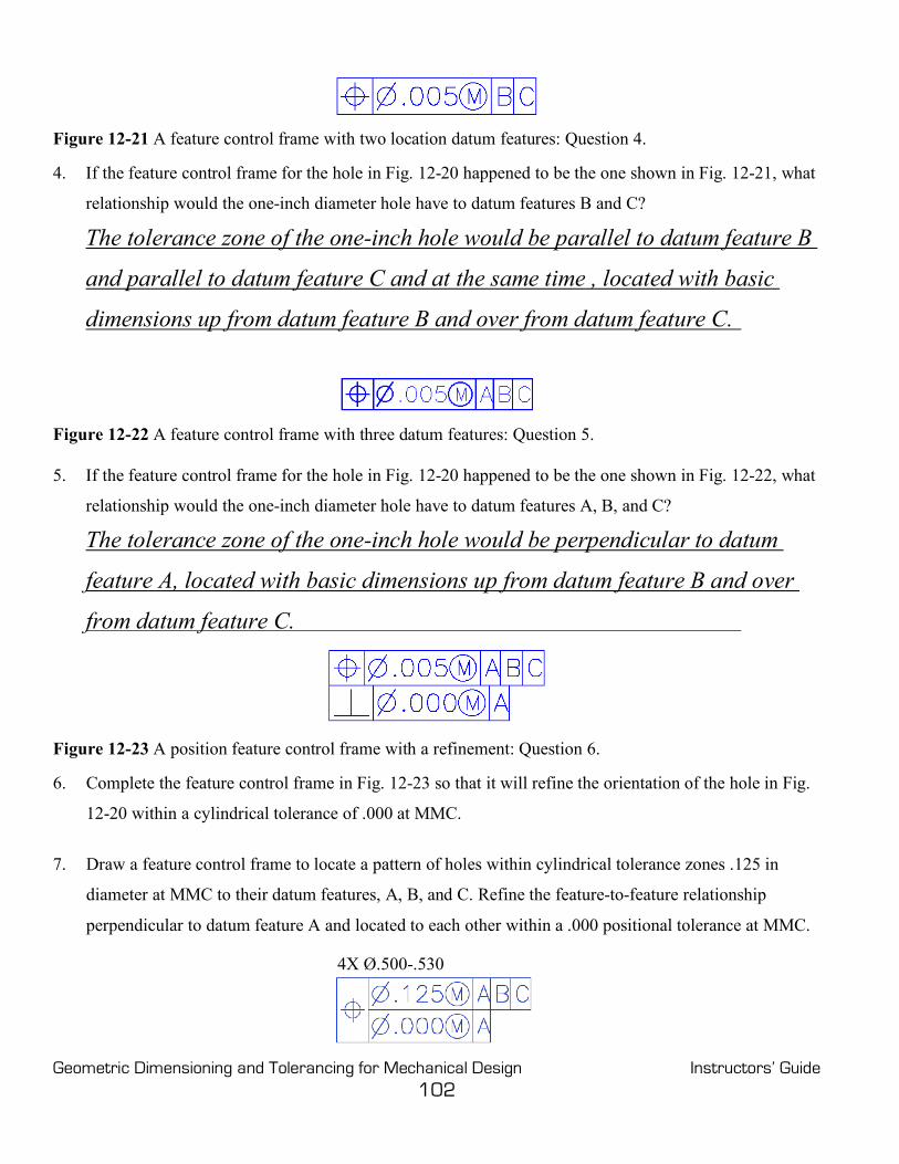
Geometric Dimensioning and Tolerancing for Mechanical Design Instructors’ Guide 102
Figure 12-21 A feature control frame with two location datum features: Question 4. 4. If the feature control frame for the hole in Fig. 12-20 happened to be the one shown in Fig. 12-21, what
relationship would the one-inch diameter hole have to datum features B and C?
The tolerance zone of the one-inch hole would be parallel to datum feature B
and parallel to datum feature C and at the same time , located with basic
dimensions up from datum feature B and over from datum feature C.
Figure 12-22 A feature control frame with three datum features: Question 5.
5. If the feature control frame for the hole in Fig. 12-20 happened to be the one shown in Fig. 12-22, what
relationship would the one-inch diameter hole have to datum features A, B, and C?
The tolerance zone of the one-inch hole would be perpendicular to datum
feature A, located with basic dimensions up from datum feature B and over
from datum feature C.
Figure 12-23 A position feature control frame with a refinement: Question 6. 6. Complete the feature control frame in Fig. 12-23 so that it will refine the orientation of the hole in Fig.
12-20 within a cylindrical tolerance of .000 at MMC.
7. Draw a feature control frame to locate a pattern of holes within cylindrical tolerance zones .125 in
diameter at MMC to their datum features, A, B, and C. Refine the feature-to-feature relationship
perpendicular to datum feature A and located to each other within a .000 positional tolerance at MMC.
4X Ø.500-.530
Geometric Dimensioning and Tolerancing for Mechanical Design Instructors’ Guide 103
8. What is the orientation tolerance for the pattern of holes specified in the answer for Question 7? Perpendicular to datum feature A within a cylindrical tolerance zone of .000 in diameter at MMC.
9. Keeping in mind that the primary datum controls orientation, explain how you would select a primary
datum on a part. Key points in selecting a primary datum feature are:
Select a functional surface
Select a mating surface
Select a sufficiently large, accessible surface that will provide repeatable
positioning in a datum reference frame while processing and ultimately in
assembly
10. How would you determine which datum feature should be secondary and which should be tertiary?
The secondary datum may be more important because it is larger than the
tertiary datum or because it is a mating surface.

Geometric Dimensioning and Tolerancing for Mechanical Design Instructors’ Guide 104
Figure 12-24 Four-hole pattern of features: Questions 11 through 17.
11. Select a primary datum feature and specify a form control for it.
12. Select a secondary datum feature and specify an orientation control for it. The virtual condition of the
mating outside diameter is Ø 4.255.
13. Tolerance the keyseat for a 1/2-inch key.
14. Tolerance the 1/2-inch clearance holes for 1/2-inch floating fasteners.
15. Are there other ways this part can be toleranced? How
Yes, the hole pattern could be datum feature C, or datum feature C could be
left off entirely.
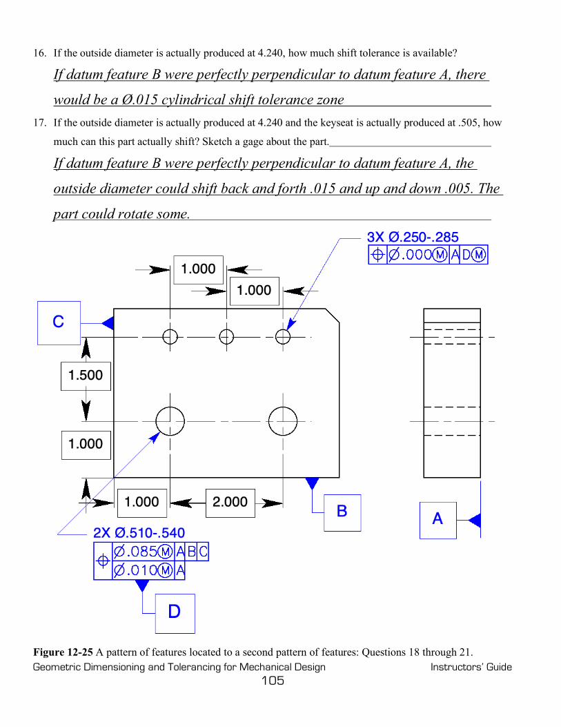
Geometric Dimensioning and Tolerancing for Mechanical Design Instructors’ Guide 105
16. If the outside diameter is actually produced at 4.240, how much shift tolerance is available?
If datum feature B were perfectly perpendicular to datum feature A, there
would be a Ø.015 cylindrical shift tolerance zone 17. If the outside diameter is actually produced at 4.240 and the keyseat is actually produced at .505, how
much can this part actually shift? Sketch a gage about the part.
If datum feature B were perfectly perpendicular to datum feature A, the
outside diameter could shift back and forth .015 and up and down .005. The
part could rotate some.
Figure 12-25 A pattern of features located to a second pattern of features: Questions 18 through 21.

Geometric Dimensioning and Tolerancing for Mechanical Design Instructors’ Guide 106
18. Locate the two-hole pattern to the surface datum features with a positional tolerance of .085 at MMC.
Locate the same two holes to each other and orient them to datum feature A within a cylindrical
tolerance of .010 at MMC.
19. Locate the three-hole pattern to the two-hole pattern within a .000 positional tolerance.
20. The two-hole pattern is specified as a datum feature at MMB, at what size does each of the two holes
apply?
Virtual condition with respect to datum feature A – Ø.500

Geometric Dimensioning and Tolerancing for Mechanical Design Instructors’ Guide 107
Problems Page 270
Figure 12-26 Tolerancing fixed fasteners: Prob. 1. 1. Tolerance the four-hole pattern in Fig. 12-26 for #10 (Ø.190) cap screws as fixed fasteners. Specify a
tolerance of .010 at MMC for the clearance holes and 60% of the total tolerance for the threaded holes in the mating part.
• How flat is datum feature A? Within .060 – in reality probably within .015 .
• How perpendicular are datum features B and C to datum feature A and to each other? ±1°

Geometric Dimensioning and Tolerancing for Mechanical Design Instructors’ Guide 108
Figure 12-27 Tolerancing a pattern of features to a datum feature of size: Prob. 2. 2. In Fig. 12-27, tolerance the center hole to the outside edges with a tolerance of .060. Refine the
orientation of the half-inch hole to the back of the part within .005. Locate the four-hole pattern to the center hole. Clock the pattern to a surface. The four-hole pattern mates with a part having four pins with a virtual condition of .250 in diameter. Give each feature all of the tolerance possible.
• At what size does the center hole apply for the purposes of positioning the four-hole pattern?
• Virtual condition of datum feature D with respect to datum feature A–Ø.500
• If the center hole is produced at a diameter of .535, how much shift of the four-hole pattern is
possible? Ø.035 if datum feature D is perfectly perpendicular to datum A

Geometric Dimensioning and Tolerancing for Mechanical Design Instructors’ Guide 109
Figure 12-28 Tolerance two features for assembly: Prob. 3.
3. Tolerance the two parts on the drawing in Fig. 12-28. Specify a flatness control of .002 on each of the primary datum features. Specify the appropriate orientation control to control the relationships between the primary and secondary datum features. Finally, complete the location tolerances for the hole patterns using a positional tolerance of .010 for the clearance holes. Use MMC/MMB wherever possible.

Geometric Dimensioning and Tolerancing for Mechanical Design Instructors’ Guide 110
Figure 12-29 Tolerancing a four-hole pattern with a composite positional tolerance: Prob. 4. 4. In Fig. 12-29, orient the center bore to datum feature A with a geometric tolerance. The mating shaft is
1.125 in diameter. Orient the ¼-inch keyseat to datum feature A, and locate it to the center bore. Position the four-hole pattern within a tolerance of .020 parallel to datum feature A, centered on the 1.130 bore, and clocked to the keyseat. Refine the location of the 4 holes in the 4-hole pattern to each other, and refine the orientation of the four-hole pattern parallel to datum feature A, perpendicular to the center bore, and parallel and perpendicular to the center plane of the keyseat within .005. Use MMC and MMB wherever possible.

Geometric Dimensioning and Tolerancing for Mechanical Design Instructors’ Guide 111
Figure 12-30 Tolerancing a pattern of features to a datum feature of size and a keyway: Prob. 5. 5. In Fig. 12-30, the inside diameter and the back are mating features. Select the primary datum
feature. (Consider a form control.) The virtual condition of the mating shaft is 1.250 in diameter. Control the relationship between the primary and secondary datum features. Locate the keyway for a ¼-inch key. Locate the six-hole pattern for 5/8-inch (Ø.625) cap screws with a positional tolerance of .014 as fixed fasteners with the mating part. Use MMC and MMB wherever possible.

Geometric Dimensioning and Tolerancing for Mechanical Design Instructors’ Guide 112
Figure 12-31 Tolerance a pattern of features to a second pattern of features: Prob. 6. 6. In Fig. 12-31, the location of the hole patterns to the outside edges is not critical; a tolerance of .060 at
MMC is adequate. The location between the two half-inch holes and their orientation to datum feature A must be within .010 at MMC. Control the six-hole pattern to the two-hole pattern within .000 at MMC. The mating part has virtual condition pins of .500 and .250 in diameter. Complete the tolerance.
• At what size does the two-hole pattern apply for the purposes of positioning the six-hole pattern? Virtual condition with respect to orientation – Ø .500
• If the two large holes are produced at a diameter of .520, how much shift of the six-hole pattern is possible? Ø.020

Geometric Dimensioning and Tolerancing for Mechanical Design Instructors’ Guide 113
Figure 12-32 Tolerance a feature of size to a second feature of size: Prob. 7. 7. In Fig. 12-32, the inside diameter and the back are mating features. Select the primary datum
feature. (Consider a form control.) The virtual condition of the mating shaft is 1.500 in diameter. Locate the keyway for a ¼-inch key. Locate the ½-inch diameter hole for a mating pin .498-.500 in diameter. Control the outside edge of the part with a tolerance of .030.

Geometric Dimensioning and Tolerancing for Mechanical Design Instructors’ Guide 114
Chapter 13
Graphic Analysis Chapter Review
Page 288
1. List the advantages of graphic analysis.
Provides functional acceptance
Reduces cost and time
Eliminates gage tolerance and wear allowance
Allows function verification of MMC/MMB, RFS/RMB, and LMC/LMB
Allows verification of any shape tolerance zone
Provides a visual record for the material review board
Minimizes storage required
2. List the factors that affect the accuracy of graphic analysis.
The accuracy of the graphs and overlay gage
The accuracy of the inspection data
The completeness of the inspection process
The drawing’s ability to provide common drawing interpretations
Figure 13-12 A composite feature control frame: Questions 3 through 7 3. A piece of graph paper with datums, true positions, tolerance zones, and actual feature locations drawn
on it is called a data graph .
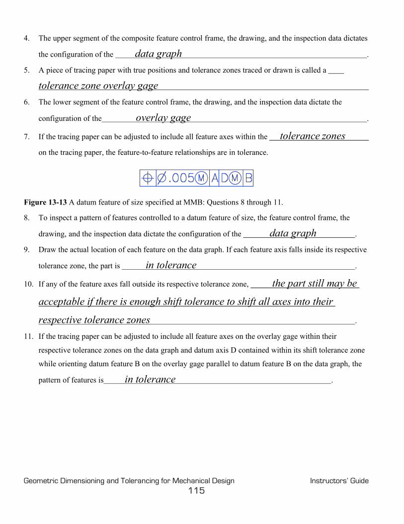
Geometric Dimensioning and Tolerancing for Mechanical Design Instructors’ Guide 115
4. The upper segment of the composite feature control frame, the drawing, and the inspection data dictates
the configuration of the data graph .
5. A piece of tracing paper with true positions and tolerance zones traced or drawn is called a
tolerance zone overlay gage
6. The lower segment of the feature control frame, the drawing, and the inspection data dictate the
configuration of the overlay gage .
7. If the tracing paper can be adjusted to include all feature axes within the tolerance zones
on the tracing paper, the feature-to-feature relationships are in tolerance.
Figure 13-13 A datum feature of size specified at MMB: Questions 8 through 11. 8. To inspect a pattern of features controlled to a datum feature of size, the feature control frame, the
drawing, and the inspection data dictate the configuration of the data graph .
9. Draw the actual location of each feature on the data graph. If each feature axis falls inside its respective
tolerance zone, the part is in tolerance .
10. If any of the feature axes fall outside its respective tolerance zone, the part still may be
acceptable if there is enough shift tolerance to shift all axes into their
respective tolerance zones .
11. If the tracing paper can be adjusted to include all feature axes on the overlay gage within their
respective tolerance zones on the data graph and datum axis D contained within its shift tolerance zone
while orienting datum feature B on the overlay gage parallel to datum feature B on the data graph, the
pattern of features is in tolerance .

Geometric Dimensioning and Tolerancing for Mechanical Design Instructors’ Guide 116
Problems Page 290
Figure 13-14 A pattern of features controlled with a composite tolerance: Prob. 1.
Feature Number
Feature Location
from Datum C X-Axis
Feature Location
from Datum B Y-Axis
Feature Size
Departure from MMC
(Bonus)
Datum-to-Pattern
Tolerance Zone Size
Feature-to-Feature
Tolerance Zone Size
1 1.002 1.003 Ø .200 .010 Ø .020 Ø .010
2 1.005 3.006 Ø .198 .008 Ø .018 Ø .008
3 3.005 3.002 Ø .198 .008 Ø .018 Ø .008
4 3.003 .998 Ø .196 .006 Ø .016 Ø .006
Table 13-3 Inspection Data for Graphic Analysis of Prob. 1

Geometric Dimensioning and Tolerancing for Mechanical Design Instructors’ Guide 117
1. A part was made from the drawing in Fig. 13-14; the inspection data was tabulated in Table 13-3. Perform a graphic analysis of the part. Is the pattern within tolerance? Yes
Figure 13-15 A pattern of features controlled with a composite tolerance: Prob. 2.
Feature Number
Feature Location
from Datum C X-Axis
Feature Location
from Datum B Y-Axis
Feature Size
Departure from MMC
(Bonus)
Datum-to-Pattern
Tolerance Zone Size
Feature-to-Feature
Tolerance Zone Size
1 1.004 .998 Ø.174 .008 Ø.018 Ø.010

Geometric Dimensioning and Tolerancing for Mechanical Design Instructors’ Guide 118
2 .995 3.004 Ø .174 .008 Ø .018 Ø .010.
3 3.000 3.006 Ø .172 .006 Ø .016 Ø .008
4 3.006 1.002 Ø .176 .010 Ø .020 Ø .012
Table 13-4 Inspection Data for Graphic Analysis of Prob. 2
2. A part was made from the drawing in Fig. 13-15; the inspection data were tabulated in Table 13-4.
Perform a graphic analysis of the part. Is the pattern within tolerance? No
(The pattern must remain parallel to datum B because datum B has been repeated in the lower segment of the feature control frame.)
If it is not in tolerance, can it be reworked? If so, how? The pattern will be in tolerance
if hole numbers 2 and 3 are enlarged by about .004.
Figure 13-16 A pattern of features controlled to a size feature: Prob. 3.

Geometric Dimensioning and Tolerancing for Mechanical Design Instructors’ Guide 119
Feature Number
Feature Location from
Datum D X-Axis
Feature Location From
Datum D Y-Axis
Actual Feature
Size
Departure from MMC
(Bonus)
Total Geometric Tolerance
1 -1.992 -1.493 Ø .278 .008 Ø .008
2 -1.993 1.509 Ø .280 .010 Ø .010
3 2.010 1.504 Ø .280 .010 Ø .010
4 2.010 -1.490 Ø .282 .012 Ø .012
Datum Ø .520 Shift Tolerance = Ø .020
Table 13-5 Inspection Data for Graphic Analysis of Prob. 3
3. A part was made from the drawing in Figure 13-16; the inspection data was tabulated in Table 13-5.
Perform a graphic analysis of the part. Is the pattern within tolerance? Yes
Fig. 13-17 A pattern of features controlled to a size feature: Prob. 4.

Geometric Dimensioning and Tolerancing for Mechanical Design Instructors’ Guide 120
Feature Number
Feature Location from
Datum D X-Axis
Feature Location From
Datum D Y-Axis
Actual Feature
Size
Departure from MMC
(Bonus)
Total Geometric Tolerance
1 -1.995 -1.495 Ø .224 .010 Ø .014
2 -1.996 1.503 Ø .218 .004 Ø .008
3 2.005 1.497 Ø .220 .006 Ø .010
4 1.997 -1.506 Ø .222 .008 Ø .012
Datum Ø .380 Shift Tolerance = Ø .005 Table 13-6 Inspection Data for the Graphic Analysis of Prob. 4 4. A part was made from the drawing in Fig. 13-17; the inspection data was tabulated in Table 13-6.
Perform a graphic analysis of the part. Is the pattern within tolerance? No
If it is not in tolerance, can it be reworked, if so, how? The pattern will be in tolerance
if all holes are enlarged to their LMC size.
Appendix A
Concentricity and Symmetry Page 301
Note: The concentricity and symmetry controls have been deleted from the ASME Y 14.5-2018 standard. However, many readers of this text continue to use or are required to read drawings toleranced to an earlier version of the standard. Consequently, the chapter in the previous (second) edition on concentricity and symmetry (Chap. 10) appears here in its entirety as App. A.
1. Both concentricity and symmetry controls are reserved for a few
unique tolerancing applications .
2. Both concentricity and symmetry employ the same tolerancing concept ; they just apply to
different geometries .

Geometric Dimensioning and Tolerancing for Mechanical Design Instructors’ Guide 121
3. Concentricity is that condition where the median points of all diametrically opposed points of a surface
of revolution are congruent with the axis (or center point) of a datum feature .
4. Concentricity is a location control. It has a cylindrical
shaped tolerance zone that is coaxial with the datum axis .
5. Concentricity tolerance only applies on a RFS basis.
It must have at least one datum feature that applies only at RMB .
6. For concentricity, the aggregate of all median points
must lie within a cylindrical tolerance zone
whose axis is coincident with the axis of the datum feature .
7. Concentricity can be inspected, for acceptance only, by placing a dial indicator on the
toleranced surface of revolution and rotating the part about its datum axis .
8. To reject parts and to inspect features such as regular polygons and ellipses, the traditional
method of differential measurements is employed.
9. The concentricity tolerance is often used to accurately control balance
for high speed rotating parts.
10. Concentricity is time consuming and expensive to inspect ,
but less expensive to manufacture than the runout tolerance.
11. Symmetry is that condition where the median points of all opposed
or correspondingly located points of two or more feature surfaces are congruent
with the axis or center plane of a datum feature.
12. Symmetry is a location control.
13. Symmetry has a tolerance zone that consists of two parallel planes
evenly disposed about the center plane or axis of the datum feature.
14. Symmetry tolerance applies only at RFS .
15. Symmetry must have at least one datum feature that only applies at RMB .

Geometric Dimensioning and Tolerancing for Mechanical Design Instructors’ Guide 122
16. The aggregate of all median points
must lie within a tolerance zone defined by two parallel planes
equally disposed about the center plane or axis of the datum feature .
17. The symmetry tolerance is independent of both size and form .
18. Differential measurement excludes size, shape, and form
while controlling the median points of the feature.
19. The symmetry tolerance is often used to accurately control balance
for rotating parts or to insure equal wall thickness .
20. Specify symmetry only when it is necessary because it is time consuming and expensive to
manufacture and inspect.
Problems Page 303
Figure A-7 Controlling the coaxiality of a cylinder: Prob. 1. 1. The mass of this high-speed rotating part in Fig. A-7 must be accurately balanced. The form of the
surface is sufficiently controlled by the size tolerance. Specify a coaxiality control for the axis of the 4-inch diameter within a cylindrical tolerance of .001 at RFS to datum feature A at RMB.

Geometric Dimensioning and Tolerancing for Mechanical Design Instructors’ Guide 123
Figure A-8 Controlling the coaxiality of an ellipse: Prob. 2. 2. The mass of the ellipse in Fig. A-8 must be accurately balanced. Specify a coaxiality control that will
locate the median points of the ellipse within a cylindrical tolerance of .004 at RFS to datum feature A at RMB.

Geometric Dimensioning and Tolerancing for Mechanical Design Instructors’ Guide 124
Figure A-9 Controlling the coaxiality of the hexagon: Prob. 3. 3. The mass of the hexagon in Fig. A-9 must be accurately balanced. Specify a coaxiality control for the
median points of the hexagon within a cylindrical tolerance of .005 at RFS to datum feature A at RMB.
Figure A-10 Controlling the symmetry of a slot: Prob. 4. 4. The mass of the part in Fig. A-10 must be accurately balanced. Specify a geometric tolerance that will
centrally locate the slot in this part within a tolerance of .005 at RFS to datum feature A at RMB.