1 internet technology netw 902 tutorial 3 mohamed esam
TRANSCRIPT
1
Internet TechnologyNETW 902Tutorial 3
Mohamed Esam

2
Outline
1. SONET/SDH2. ATM 3. ISDN4. Dialup5. DSL6. IP Addressing
Exercise 3.
Access Network
Core Network
3
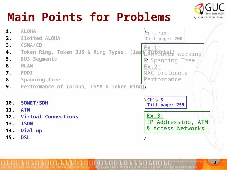
Main Points for Problems 1. ALOHA2. Slotted ALOHA3. CSMA/CD4. Token Ring, Token BUS & Ring Types. (last Tutorial)5. BUS Segments6. WLAN7. FDDI8. Spanning Tree9. Performance of (Aloha, CSMA & Token Ring)
10. SONET/SDH11. ATM12. Virtual Connections13. ISDN14. Dial up15. DSL
Ch’s 1&2Till page: 200
Ch’s 3Till page: 255
Ex.1:LAN-Inter working& Spanning TreeEx.2:MAC protocols Performance
Ex.3:IP Addressing, ATM& Access Networks

4
16.Internet Arch. & IP Addressing.17.ARP18.MTU19.Routing Functions20.Forwarding21.Routing Principles22.Distance Vector Algor.23.Link State Algor.24.Path Vector Algor.25.Routing in Internet.26.Internet Routing Protocols27.ARQ28.UDP29.TCP30.QoS
Some of Ch’s 4&5Till page: 554
Ex.4:Distance Vector &Link State Routing
Ex.5:TCP

5
IP Addressing

6
IP Addressing
• IP Addressing:– Subnetting: a network is divided into smaller subnets with
each subnet having its own subnet address.• Classless• Classful
– Benefits:• Faster routing• Smaller broadcast domains• Reduced network traffic• Simplified management
– Supernetting
• IP v4 4 Bytes (Dotted decimal x.x.x.x)• IP v6 16 Bytes (128 bits)

7
Classless Subnetting
• The IP address is divided into two part:– Network Addr. (n bits)– Host Addr. (32 – n bits for IPv4)– IP Address with Prefix Notation: ex. 120.112.2.1/n
• Subnet Mask:– Example if n=26 subnet mask is:– 11111111 11111111 11111111 1100000– And gate is used to get the Network address using the
subnetmask

8
Classful Subnetting
• Special case of classless subnetting when n has defined values.

9
Supernetting
• Opposite to subnetting• Example:
– If A0(Network 0 Address)=00000000.11111111.00000000.00000000/2
4– & A1(Network 1 Address)=00000000.11111111.11111111.00000000/2
4 Aagg=
00000000.11111111.00000000.00000000/16

10
IP Static Routing
• Assume 2 BUS topology networks connected by router. The router is the gateway for each network to the other one.
• Station (1.1) will send data to station 2.3.• Next Hop station is the first station will receive the data from the Tx.• Interface is the station in the network domain that will send to the next hop
or the Rx station. • Router knows that address (1.x) is in network 1 and (2.x) is in network 2

11
Exerc.3 Prob.1

12
Asynchronous Transfer Mode (ATM)
13
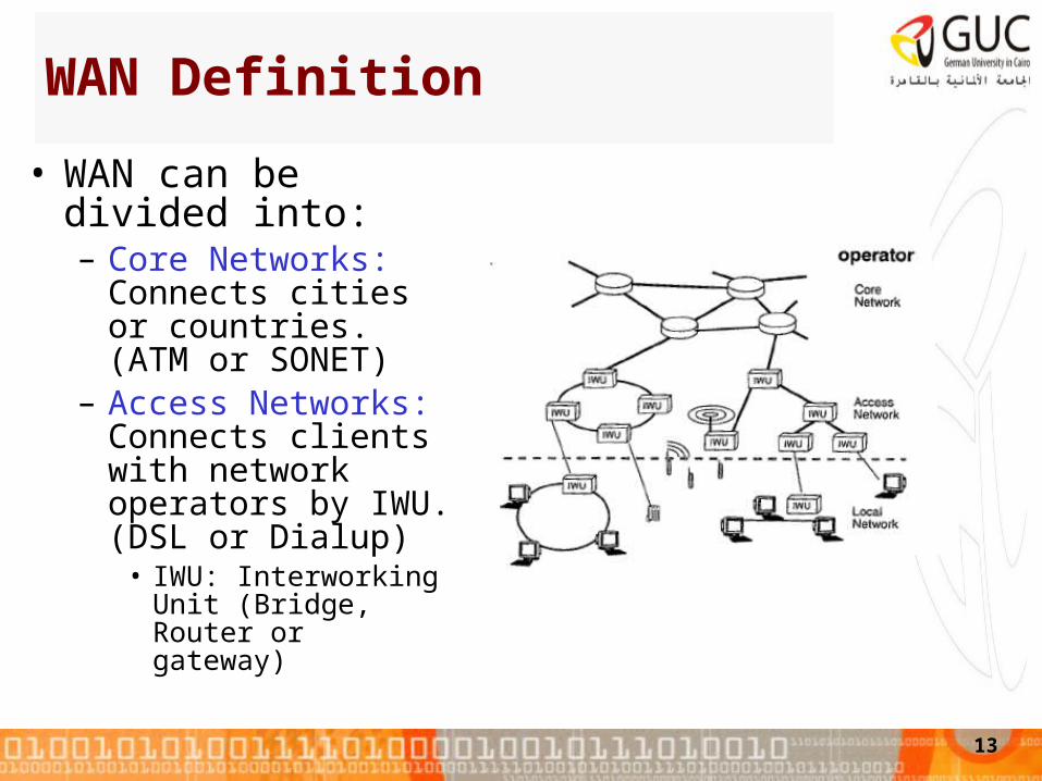
WAN Definition
• WAN can be divided into:– Core Networks:
Connects cities or countries. (ATM or SONET)
– Access Networks: Connects clients with network operators by IWU. (DSL or Dialup)
• IWU: Interworking Unit (Bridge, Router or gateway)

14
ATM
• Is designed to integrate all communication services with different traffic classes:– Constant bit rate (phones)– Variable bit rate (video)– Packetized traffic
• By: – Packetization into small
constant size cells.– Asynchronous multiplexing into
high transmission channels.

15
MUX
`
Wasted bandwidth
ATM
TDM
4 3 2 1 4 3 2 1 4 3 2 1
4 3 1 3 2 2 1
Voice
Data packets
Images
Figure 7.37Leon-Garcia & Widjaja: Communication NetworksCopyright ©2000 The McGraw Hill Companies
Asynchronous Multiplexing

16
Virtual Path & Virtual Connections
• ATM is a Connection Oriented Technology.• Virtual Channel (VC): the channel of ATM cell identified by
VCI (VC ID)• Virtual Channel Connection (VCC): sequence of VC’s links
to establish a path between terminal equipments (TEs).• Virtual Path (VP): group of VC’s identified by a (VPI)• Virtual Path Connection (VPC): sequence of VC’s links to
establish a path between terminal equipments (TEs).• Each cell carriers both transmission VPI and VCI

17
ATM Cell
• Header details in Page 233

18
Cell Switching• Base on the
connection establishment phase, switching tables are used.
• In the switching table, each input VCI /VPI is mapped to another output VCI/VPI and the corresponding output port number.
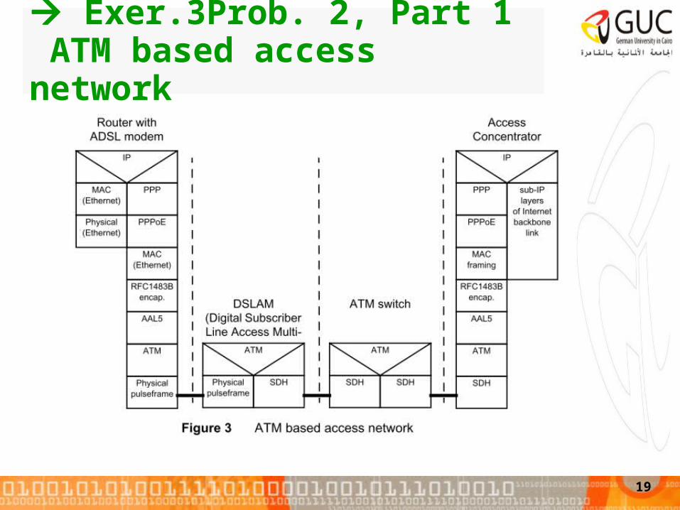
Exer.3Prob. 2, Part 1 ATM based access network
19

20
AAL
ATM
User information
User information
AAL
ATM
PHYPHY
ATM
PHY
ATM
PHY
…
End system End systemNetwork

21
Ethernet Frame
Ethernet FrameCS-header Pad CS-trailer
Cellheader
Cellpayload
SAR-PDUheader
SAR-PDUpayload
SAR-PDUtrailer
SAR-PDUheader
SAR-PDUpayload
SAR-PDUtrailer
Higherlayer
Convergence Sub-layer (CS)layer
Segmentation & Reassembly (SAR)layer
ATMlayer
Cellheader
Cellpayload
Adaptation Layer : A detailed view
AAL

22
AAL5
• The most Common used AAL type.• CPCS payload: The actual information that is sent by the user. • Pad: Padding bytes to make the entire packet (including control and CRC)
fit into a 48-byte boundary. • UU: CPCS user-to-user indication to transparently transfer CPCS user to
user information.• CPI: Common part indicator is a filling byte (of value 0). This field is to
be used in the future for layer management message indication. • Length: Length of the user information without the Pad (65535). • CRC: CRC-32. Used to allow identification of corrupted transmission.
1216
User Data
Divided into 53 bytes

23
Synchronous Digital Hierarchy (SDH)
• SDH is used to integrate ATM cells in the transmission system
• Synchronous Optical Network (SONET) is the protocol for North America and Japan by ANSI while SDH is the definition for Europe by ITU-T.
24
Synchronous TDM• In Synchronous TDM, the time slots are
preassigned to sources and fixed.– The time slots for each source are
transmitted whether or not the source has data to send
– capacity is wasted to simplify the hardware implementation
– It is possible for a synchronous TDM device to handle sources of different data rates. • For example:
– the slowest input device could be assigned one slot per cycle,
– faster devices are assigned multiple slots per cycle.

25
Synchronous TDMStation A is Faster
Asynchronous (Statistical) TDMStation B&D are idle
Normal TDM
26
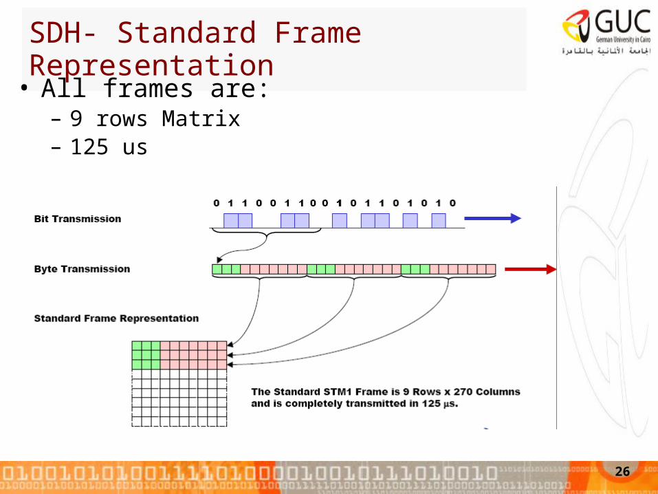
SDH- Standard Frame Representation
• All frames are:– 9 rows Matrix– 125 us

27

28
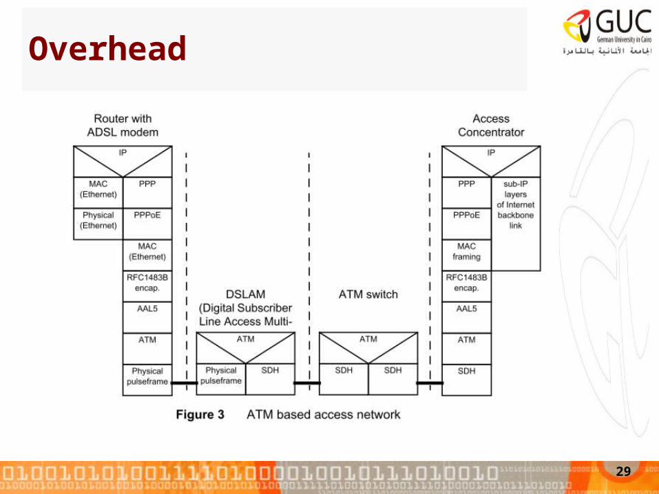
Overhead
29

30
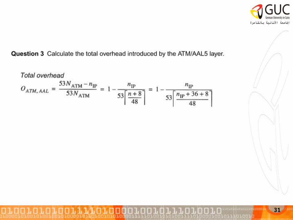
Check slides4, 7
Given in the problem Encapsulation Headers ATM CS layer
sizeheaderlengthframetheisbits16),12( 16 n
Preamble and SFD are not considered as given in the problem
31

Part 2 Ethernet based access network
• ATM technology in DSLAM is replaced by an Gigabit Ethernet interface.
• Ethernet frames in the VLAN switch are encapsulated using the Generic Framing Procedure (GFP).
• GFP adds a header of 8 bytes, but does not include the preamble and the start frame delimiter of the Ethernet frame.
32
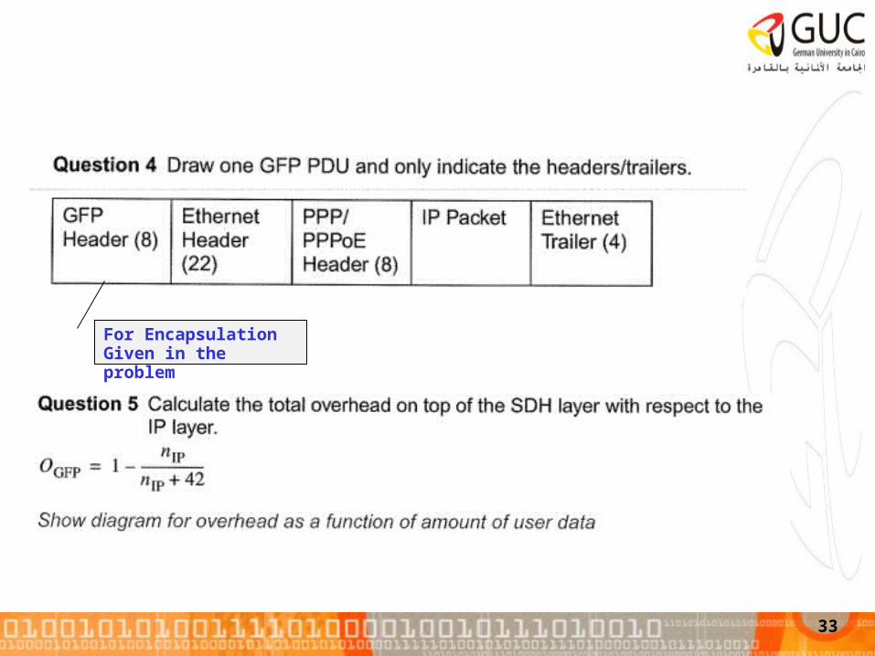
33
For EncapsulationGiven in the problem

34