1. introduction · 2012-06-18 · increasing the speed of the flywheel rather than the moment of...
TRANSCRIPT

1. Introduction
The energy scenario in the world is calling for efforts towards more efficient use of
electrical energy as well as improved quality of its delivery. Due to limited budgets, the
alternative is having different levels of supply quality. This issue involves the usage of
equipments applying the concept of energy storage devices like batteries or flywheels.
The demand for these equipments is increasing and thus their usage is increasing more
and more. The type of energy storage system that is most widely researched and used
especially in the last period is the Flywheel Energy Storage System (FESS). Due to the
advancements in machines and power electronics, the flywheel is becoming more
popular. Many feasible projects employing the FESS have been implemented all over the
world [9].
The main problem in this project is to apply and control a two way energy flow
scheme so that energy is injected into the flywheel in the form of kinetic energy, and
drawn from the machine driving the flywheel in the form of electric energy.
Flywheels are one of the oldest forms of energy storage and they have been used for
thousands of years. The potter wheel is one of the earliest applications of the flywheels.
The kinetic energy stored in the flywheel results from spinning a disk or cylinder coupled
to a machine’s rotor. This energy is proportional to the flywheel mass and the square of
its rotational speed so that:
E = ½ I . ω2
where I is the moment of inertia in Kg.m2 and ω is the rotational speed in rad/s.
Even though the FESS can have many applications including uninterruptible power
supplies (UPS), dynamic voltage compensators, overload compensators, and start-up of
1

standby diesels, we will mainly focus on the FESS as an overload compensator. In this
application, the FESS supports the main grid by supplying power to part of the load in
case of overload. This occurs when there is a voltage or frequency dip in the main grid
and thus it is not capable, for a few seconds, to supply all the power needed by the load.
So, the grid gets the help from the FESS which has stored kinetic energy. Therefore, the
main purpose of the flywheel is to accumulate rotational kinetic energy which can be
injected into the electric system whenever it is required. The system is basically
composed of a machine (either AC or DC) and its controlling power electronics.
Therefore there are a lot of advantages for the FESS such as its high power efficiency,
mechanical load coupling, and using no hazardous chemicals; thus being environment
friendly. The efficiency of the whole system is directly proportional to the efficiency of
the power electronics and machine used. A regular machine nowadays has efficiency
above 85% and near 90%, while the efficiency of the power electronics nowadays
exceeds 95%.
We preferred to use flywheels instead of batteries because, in addition to the
mentioned advantages, flywheel systems have longer lives than batteries. Regular
batteries have a life not more than 2 years and good quality batteries have a life extending
to 7 years. However, the machine driving the flywheel can live for more than 20 years
with proper maintenance, and the flywheel itself can have a very long life if not exposed
to mechanical damage, and this is usually the case. Even though batteries might have
lower initial costs but the longer expected life of the FESS compensates for this problem.
The project was first proposed by our supervisor Prof. S. Karaki. This topic is being
heavily researched around the world especially in the US department of energy.
2

A lot of projects based on the FESS have been implemented in several countries
especially USA and several European countries. However, with the advancements in
power electronics, machines, materials and magnetic bearings of machines, new ideas are
being researched and new projects are implemented. High speed flywheel systems (more
than 30,000 rpm) are now in the prototype stage and it is expected that these systems be
in market after 5 to 10 years [10]. So although the flywheel as an energy storage system
has been used from thousands of years, research in this subject is still taking place and it
is expected to keep in progress for several years to come. From our literature survey, we
noticed that the maximum speed that has been reached in experiments is around 60000
rpm but it is still not considered to operate well due to the resulting speed oscillations
which cause high speed errors.
As a summary, the flywheel energy systems are applied nowadays in several
domains. Usually, rotors in FESS operate at 4000rpm or less and they are made from
metal. Advanced flywheels can rotate above 20,000 rpm in vacuum enclosure and they
are made in this case from high strength carbon composite filament. In high speed
applications, magnetic bearings are necessary to reduce the friction losses. Flywheel
systems can have efficiency as high as 80%. Most current and future researches focus on
increasing the speed of the flywheel rather than the moment of inertia because its kinetic
energy increases geometrically with speed. Disadvantages of the flywheel include the
danger of explosive shattering of the massive wheel due to overload, thus safety
concerns.
3

1.1 System Description
Our circuit consists of a flywheel coupled to a DC machine which is connected to a
boost converter which is in turn connected to a rectifier/inverter bridge. The
rectifier/inverter bridge is connected via a set of switches to the main grid and to the load.
In addition, the main grid is also connected to a permanent load. The following block
diagram represents a simple overview of our project:
Fig.1: Block diagram of the flywheel energy storage system (FESS)
4

2. Literature Review
2.1 Papers Review
2.1.1 UPS Flywheel Energy Storage System [11]
This paper talks about the application of flywheel as an uninterruptible power supply
(UPS) and a dynamic voltage compensator. The figure below shows the circuit used:
Fig.2: Flywheel energy storage system [11]
The experiment done uses an AC machine coupled to a flywheel.
There are three modes for the system and each includes a set of switches closed and
others open:
The charging mode: in which the grid supplies power to the load and to the
machine acting as a motor resulting in the rotation of the flywheel. Rect/Inv1 in
5

this case acts as a rectifier to change from AC voltage from the supply to DC
voltage and then Rect/Inv2 acts as an inverter to change the DC voltage again to
AC to feed the machine.
Compensation mode: in which the flywheel supplies a percentage of the load and
thus supplements the supply in feeding the load. In this case the machine acts as a
generator, Rect/Inv 1 acts as a rectifier and Rect/Inv 2 acts as an inverter.
UPS mode: in which the flywheel supplies the entire load and the grid is
disconnected from the load. Rect/Inv 1, Rect/Inv 2 and the machine are as in the
compensation mode.
The inverters are controlled by PWM signals.What is interesting in this paper is the
use of series transformers needed in the case of UPS mode to provide a wide range of
operation of the system.
This example illustrates the use of transformers. If the voltage dip that occurs at the
load is 40V, then the flywheel connected to the generator of rating 277 V rms (this is the
rating used) need to be converted to 40V by using very small modulation index of SPWM
firing signals. This is undesirable as we must use in this case high frequency high
amplitude pulses. To overcome this problem, the transformer ratio is 5:1. In this case,
40V dip at the load will require 200V from generator which increases modulation index.
In case the voltage dip is 100V, we must inject 500V by the generator. Here, the boost
converter is used which can raise the voltage of the generator and thus supply the voltage
needed by the load. Thus a novel control scheme is used in this experiment and the result
is an FESS which acts as a UPS or dynamic voltage compensator and allows for a
sufficient range of operation.
6

2.1.2 Control of a Power Circuit Interface of a Flywheel-based Energy Storage
System [9]
The paper presents a flywheel energy storage system (FESS) using a switched
reluctance machine (SRM). This system is to be used as a static shunt compensator.
Superconducting magnetic bearing is used to decrease the friction losses. SRM provides a
wide range of operation from zero up to several ten thousands rpm in addition to its
having high reliability.
The figure below shows the circuit implemented in the FESS:
Fig.3: Control of power electronics circuit for flywheel energy storage system [9]
The acceleration of the SRM is controlled by measuring the difference between the
dc link capacitor voltage and a given reference value (as shown below):
Fig.4: PI controller for a switched reluctance machine [9]
7

Increasing speed rather than mass:
From experimental results, it was shown that the energy of the flywheel can be
increased better by increasing the speed while keeping the mass constant rather than
increasing the mass and keeping the speed constant. However, some problems arise with
increasing speed. These are:
- Increased losses due to air resistance
- Increased probability of mechanical failure due to higher speed
- Increased losses due to bearing friction
- Increased magnetic losses due to higher frequency of stator currents.
Magnetic losses can be reduced by correctly designing the machine with proper
selection of the core material. Windage and friction losses can be reduced by using
vacuum and superconducting magnetic bearing.
As a conclusion, this paper has presented the SRM flywheel system and showed that
SRM is a good choice as a driving machine, and thus the power quality in electric energy
systems has been enhanced.
2.1.3 High Efficiency Energy Conversion and Drives of Flywheel Energy Storage
System using High Temperature Superconductive Magnetic Bearings [4]
When the load on an electric system increases, the power system is made unstable,
and lots of problems arise like voltage sags. To improve the quality of power, systems
like UPS systems are usually used. One option is a UPS based on lead acid batteries, but
this has many disadvantages like low efficiency, gas pollution, high cost for maintenance
and change, weight and size. Thus, other options are considered, the best of which are a
8

flywheel energy storage system. This paper presents an FESS using high temperature
(HTS) superconductive magnetic bearing and permanent magnet synchronous motor.
Different types of motor/generators have been examined. An induction motor is robust,
inexpensive, and the motoring and regenerating power can be controlled by adjusting the
slip power. However, it is difficult to have high efficiency at high speed operation. Also,
other types like reluctance motors and synchronous motors have been studied, but each
has its problems when considering HTS magnetic flywheel system. It is proved that the
validity of this system used (HTS magnetic Flywheel system) is superior to the
conventional electro-mechanical flywheel system. The maximum speed reached in the
experiments is 40,000rpm.
2.1.4 Modeling and Analysis of a Flywheel Energy Storage System for Voltage Sag
Correction [7]
Flywheels can be designed for low speed and high speed operations. Flywheel
systems operating at low speeds have some advantages like: lower cost and use of proven
technologies. Disadvantages are less stored energy per volume and higher losses. This
paper examines a low speed flywheel system coupled to an induction motor. In this
circuit, two rectifier/inverters are used. It was shown that the main advantage of the FESS
tested is its low cost, high energy density, and the efficiency in mitigating long duration
voltage sags.
9

2.1.5 Advanced Motor Control Test Facility for NASA GRC Flywheel Energy Storage
System Technology Development Unit [5]
This paper discusses the operation and control of a flywheel mounted on a 4-pole
permanent magnet synchronous machine. This synchronous machine needs control due to
its sensitivity to speed changes. The control method is using the d-q axes control method.
The motor is controlled successfully at a speed of 20000 rpm. Testing speeds reached
60000 rpm but the control method was unable to eliminate the high value of speed
oscillation which caused in turn a large error in the current supply.
2.1.6 Spinning Reserve [3]
This paper is based on Piroutte, a flywheel energy system developed by Prof. Paul
Acarnley at the University of Newcastle. Combining a flywheel, a motor, and a generator
results in a novel energy storage system.
The world’s major problem is in energy storage rather than energy production.
Flywheel provides simple, short term energy storage. The limitations of battery
technology hindered the widespread use of many electric vehicles and motivated the use
of new-old electric storage system. Flywheels can be used for many electrical
applications and in combination with other generator systems to cover short-term power
fluctuations. Also they can be introduced to the telecoms market to provide secure,
autonomous power supply for network nodes.
Flywheels can be easily integrated to electric machines due to their rotational
characteristics. The design approach consists of strong light weight materials and solid-
state electronics.
10

The important design aspect of the flywheel system is that the kinetic energy of a
rotating body is directly proportional to the moment of inertia and the square of the
angular velocity, so we seek for a massive, high-speed flywheel. The flywheel should be
rigid and balanced and is usually made from carbon and glass fiber composite material. A
cylindrical shaped flywheel has many advantages in terms of maximum energy, avoiding
resonance, and space allocation.
The most important operational aspect is to maintain a constant voltage to the load;
i.e. to compensate any power supply failure or frequency variations. At start-up, the
flywheel will rotate gaining kinetic energy till it reaches its maximum speed. At this
moment, it will be switched off allowing for energy dissipation until zero due to frictional
losses. Then the set will be turned on again till reaching the maximum speed again. The
maximum speed of the flywheel is determined by the construction. The stored kinetic
energy will be supplied to the load when needed. Note that not all stored energy is
recoverable.
The power flow into and out of the flywheel should be controlled. Thus its speed is
controlled to supply constant frequency and supply. This is done by means of a three
phase voltage source inverter that operates as an inverter when power is supplied to the
flywheel and as a rectifier when power is drawn from the flywheel. Benefits can be
summarized as: wide operating temperature range, high cycling capability, guaranteed
energy content, long design life, maintenance free, and low losses.
The marketing plan for a flywheel system is mainly to replace batteries. These
systems present no troubles to temperature extremes, life cycle decrease due to
charge/discharge cycles, and are designed to be almost maintenance free.
11

2.2 Components Review
In this section, we will present the available alternatives for each of the basic system
components.
2.2.1 Electric Machine
According to the literature review that we have done and to our knowledge in the
field of machines, the basic options that we have for the machine carrying the flywheel
are:
• Induction Machine (AC)
• Synchronous Machine (AC)
• DC Machine
• Reluctance Machine
Each of the above has its own advantages and disadvantages as follows:
2.2.1.1 Induction Machine
The induction machine is almost a perfect motor. The main feature of the induction
motor is its field excitation. The induction motor has a short circuited field winding
which causes it to be self starting. Therefore, the induction motor can have no field
brushes and slip-rings.
Induction motors include two types: wound rotor and squirrel cage rotor. The wound
rotor type has its rotor current accessible at the stator brushes, thus extra resistance can be
inserted in which we take advantage in modifying torque-speed characteristics. Wound
rotor induction motor, however, is more expensive than squirrel cage induction motor and
requires much more maintenance because of the wear associated with their brushes and
slip rings [2]; thus, they are rarely used.
12
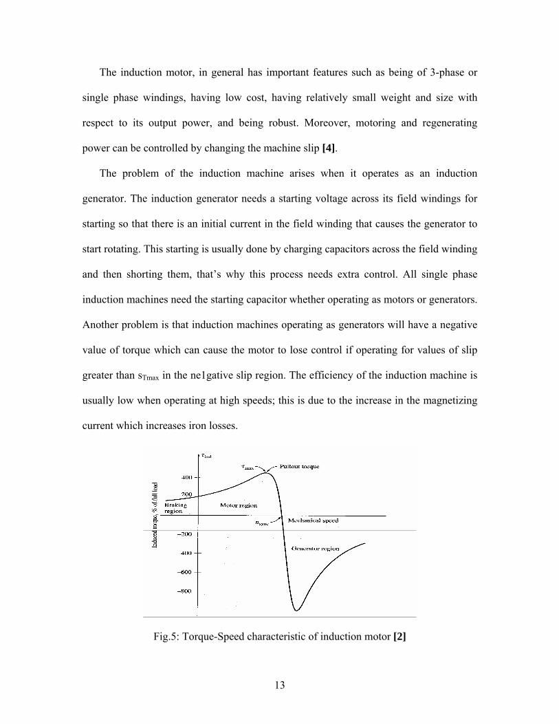
The induction motor, in general has important features such as being of 3-phase or
single phase windings, having low cost, having relatively small weight and size with
respect to its output power, and being robust. Moreover, motoring and regenerating
power can be controlled by changing the machine slip [4].
The problem of the induction machine arises when it operates as an induction
generator. The induction generator needs a starting voltage across its field windings for
starting so that there is an initial current in the field winding that causes the generator to
start rotating. This starting is usually done by charging capacitors across the field winding
and then shorting them, that’s why this process needs extra control. All single phase
induction machines need the starting capacitor whether operating as motors or generators.
Another problem is that induction machines operating as generators will have a negative
value of torque which can cause the motor to lose control if operating for values of slip
greater than sTmax in the ne1gative slip region. The efficiency of the induction machine is
usually low when operating at high speeds; this is due to the increase in the magnetizing
current which increases iron losses.
Fig.5: Torque-Speed characteristic of induction motor [2]
13

2.2.1.2 Synchronous Machine
The main advantage of a synchronous machine is its ease of operation as either a
motor or a generator. The only difference in this operation is the direction of the current
flow. Another advantage is its simple equivalent circuit that consists of a voltage source,
inductance, and resistance. The speed and current flow in the synchronous machine can
be regulated by varying the field current using a variable field resistor. This field winding
has a disadvantage of being connected to brushes. These brushes always need
maintenance and checking. In addition, high power losses can arise due to the brush
voltage drop, especially in machines involving high currents. This problem is eliminated
in case the rotor of the synchronous machine is a permanent magnet. This machine
operates perfectly when the speed is maintained constant, and that’s why it is called a
synchronous machine, but the speed regulation of this machine is high so that any slight
change in the operating speed can cause the machine to lose synchronism for a while. The
starting of the synchronous machine is done either by a variable frequency drive (VFD)
or by an amortisseur winding (in the wound rotor designs). The first method is
complicated and expensive while the second one doesn’t work for the permanent magnet
case because it needs external terminals of the field winding, which doesn’t exist in this
case.
2.2.1.3 DC Machine
DC Machines are known for their simplicity and ease of control. The different
construction schemes of a DC machine varying between series, parallel, and compound,
in addition to being cumulative or differential, expands a broad collection of options for
14

the connection of a DC machine. The parallel or shunt DC machine is best used for speed
control. Inspite the fact that the DC machine needs terminals on the stator for excitation
by being either shunt, series, or separately excited, and even though it is not cheap, the
main advantage of the DC machine is being supplied by a DC source which eliminates
the problem of frequency variation of the rotor as in the AC machine cases. They also
have relatively small sizes for their output power. DC machines can be operated as either
motors or generators without the starting problem.
2.2.1.4 Reluctance Machine
Reluctance machine has a very simple structure, so, it may be used in high speed
applications. These machines are basically AC machines and they are mainly used as
motors because they have a special characteristic of controlling the angle of the shaft.
The basic operation of these machines is by aligning the rotor, which is basically a piece
of metal such as steel, to a varying magnetic flux. This rotor is placed in an air gap trough
in which the magnetic flux is passing. The greater the number of poles in the machine
which cause different flux lines, the wider range of angles that result. As the rotor aligns
with the stator and moves to a position where the reluctance is minimum, continuous
movement of the rotor can result by continuous excitation of phase coils of stator poles.
The main advantage of this machine is its wide speed range (from zero to several ten
thousands rpm) and its reliability and ability to tolerate faults [9]. The main problem of
this machine is that the air gap between the rotor and the stator while operating must be
fixed. When loading the rotor shaft with a heavy flywheel, the air gap will vary with the
vibration of the rotor due to the heavy mass of the flywheel which might cause the rotor
15

to hit the armature if the air gap was initially narrow. Another problem is the control of
the shaft rotation which needs power electronics giving control signals for each pole. This
causes an increase in price and complexity of the motor set. These machines are rarely
used as generators except in the case of permanent magnet rotor.
2.2.2 Single Phase Inverter
The DC/AC inverter we are using consists of 4 switches connected on two arms, two
switches on each. It is important that no two switches on the same arm close at the same
time because this will create a short circuit on the input. Thus care must be taken when
designing the switching patterns of these switches. We have come over two types of
switching control, PWM with bipolar voltage switching and square wave switching.
2.2.2.1 PWM with Bipolar Voltage Switching
This method involves a certain pattern of switching used in the DC/AC inverter
bridges. A sinusoidal signal (Vcontrol) is compared to a triangular signal (Vtri) using a
comparator. If Vcontrol > Vtri, the diagonally opposite switches close, and if Vcontrol <Vtri,
then the other two diagonally opposite switches close. 2 switches (not on the same arm)
close simultaneously, otherwise, they open. This results in output pulses (PWM
waveform) whose magnitude depends on that of the DC input voltage Vd. The pulses are
either +Vd or –Vd. This scheme decreases harmonics because the pulse width at the peak
of the sinusoidal signal is wide, while it is narrow when the signal is close to zero [6].
When the output is fed to a low pass filter, an analog signal results and this signal
represents the fundamental component of the PWM waveform. The magnitude of this
16

fundamental component depends on that of the input DC voltage and the amplitude
modulation ma, which is equal to peak of sinusoidal signal divided by peak of triangular
signal, ma = Vsp / Vtri,p .
Vo (of fundamental component) = ma x Vd ; (if ma<=1)
Vd < Vo (of fund. component) < (4/pi) x Vd ; (if ma >1)
The triangular signal frequency is called the switching frequency or carrier frequency.
It is important to note here that the frequency of the fundamental component of the PWM
waveform after low pass filter is the same as that of the sinusoidal signals used and which
is called the modulating frequency. Thus, PWM switching is important because we can
control the frequency of the output AC voltage by just varying that of the sine signals
before the comparator [6].
One main disadvantage of the PWM scheme is that it is not very easy to implement in
inverters because inaccurate switching would create a lot of short circuits by incorrectly
closing any two switches of the same arm.
2.2.2.2 Square Wave Switching Scheme
In this scheme, we cannot control the output magnitude of the inverter as in the PWM
case by simply changing the amplitude modulation. Rather, we have to change the
magnitude of the input voltage. Thus, if the output voltage needs to be controlled, we
usually use square wave switching scheme only if the input voltage is controllable.
The relation is:
Vo (of fundamental freq. component) = (4/pi) x Vd.
Each switch is on for a duty ratio of 0.5 and thus two switches are on at any instant.
17

One advantage of this scheme is that switches change their state only twice per cycle.
This is important at high power level because switches have slower turn on and turn off
speeds. Another advantage is that this type of switching is easier to implement for the
control of inverters, unlike PWM scheme.
2.2.3 Low Pass Filter (LPF)
2.2.3.1 RC Filter
When the FESS is in the overload compensation mode, the generator supplies DC
voltage. This DC voltage is the input of the inverter connected to the machine. The
inverter uses Pulse Width Modulation (PWM) or square wave switching for its switching.
The output of this inverter is a PWM waveform. To change from this PWM waveform to
analog signal by extracting the fundamental waveform, we need to use an analog Low
Pass Filter (LPF).
Fig.6: Low Pass Filter in frequency domain (from www.microchip.com )
If we compute the Fourier of the PWM waveform, we can see that there is a
fundamental component and lots of harmonics (as we can see in the figure above). Thus
we need to use a low pass filter that filters all harmonics and extracts the fundamental
component so that we can get an analog signal. A simple RC low pass filter can be
implemented in our case because it is not expensive and easy to build. To determine the
values of R and C, we must first determine the bandwidth of the low pass filter. fbw must
18

be << fpwm where fpwm is the frequency of the triangular signal used in the comparator of
the PWM switching.
Fig.7: Bandwidth of the desirable signal (from www.microchip.com )
fbw can be computed by dividing fpwm by a constant K. K is usually between 3 and 10.
After determining fbw, we can use the formula RC=1/(2*pi*fbw).
Now, by selecting a value for R, we can easily calculate the value of C.
2.2.3.2 LC filter
The LC filer is another type of low pass filter but it is of higher order than the RC
filter. The RC filter is of first order while the LC filter is of second order. The LC filter is
made of a capacitor and inductor and can be of a pi-shape (as shown in the figure below).
The output is taken across the capacitor.
Fig.8: LC Filter Design (from www.microchip.com )
The main advantage of this type of filter is reducing the losses that are available in
the RC filter due to the resistive component R. Another advantage is having a sharper
19

edge at the corner frequency which causes fewer harmonics and eliminates unwanted
frequencies that are even near to the corner frequency.
Practical LC filters can be composed of one inductor and another capacitor where the
output is taken from the capacitor. From [8] we got the following transfer function for the
second order LPF:
H(s) = a0 / (s2 + s. ω0/Q + ω02)
The DC gain is given as a0 / ω02, and Q is the quality factor. To get an almost ripple
free low pass region, Q is taken as 1/√2 so that the filter is a butter-worth one.
20

3. Design and Analysis
In this section, we will design our FESS based on the alternatives discussed above.
We have chosen our components taking into consideration many criteria including
availability, efficiency and reliability. As we will discuss later, the components chosen in
our design are: DC machine, Square wave inverter and LC low pass filter.
The following is the block diagram of our FESS (also shown before):
Fig.9: Block diagram of the flywheel energy storage system
There are two modes for our FESS:
1) Charging mode: In this case, the source supplies energy to both the
motor/generator and the load. The machine we are using is operating as a motor
and the rectifier/inverter bridge is operating as a rectifier. This is due to the fact
that the supply voltage is AC while the motor connected to the flywheel needs a
DC input voltage.
21

2) Overload compensation mode: In this case, we will assume that an additional load
is connected to the grid causing an overload on the supply. The flywheel in turn
helps the source in supplying power to this load, thus this load is disconnected
from the grid and connected to the FESS. The motor/generator operates as a
generator and the inverter/rectifier bridge operates as an inverter so that the DC
output from the machine changes to AC voltage and feeds the additional load.
3.1 DC Machine
After studying different types of machines, we have decided to use the DC machine.
This is for several reasons. The disadvantages of the other machines come on top of these
reasons. We have mentioned previously these disadvantages, for example: induction
machine requires a capacitor to supply its starting voltage. In addition to this, the use of a
DC machine for our project eliminates one inverter/rectifier from our circuit compared to
the use of an AC machine. This is because when using an AC machine, we have first to
rectify the AC voltage coming from the grid (in case of charging) and then invert it to AC
by another inverter so that we can vary the frequency and make it similar to that of the
AC machine. Also, in the compensation mode, the output of the AC generator must be
first rectified and then inverted to make it at the same frequency of the supply voltage, so
that they will be synchronized and fed to the load. However, in a DC machine, the AC
voltage coming from the grid in case of charging needs only to be rectified, and the DC
output coming from the DC generator, in case of compensation, needs only to be inverted
so that it will be fed to the load or grid. By this elimination of one inverter/rectifier, we
reduce the complexity of our circuit.
22

Furthermore, the availability of the DC machine at our machines lab has eliminated
the main disadvantage of these machines which is their high cost. The DC machine will
be connected as separately excited since when disconnecting the machine from the
supply, we will not affect the armature current and thus the power generated by the DC
generator in the overload compensation mode.
The following two machines are available:
Table1: Characteristics of DC machines available in the Machines Lab
SM 2643 DC Machine MV 1006-225 DC Machine
Motor 0.4 KW, 1500 rpm 1 KW, 1400 rpm (shunt),
1150 rpm (series)
Generator 0.4 KW, 1800 rpm 1.2 KW, 1400 rpm
Rotor 160 V, 3.7 A 220 V, 6 A
Excitation 190 V, 0.12 A 220 V, 0.55 A
I.P. 54 23
Temperature Class 155 oC 130 oC
We chose the second machine since it is of larger size and a larger flywheel can be
coupled to its shaft so that the generator would run for a longer time. This will improve
system operation during testing process.
23

3.2 Inverter
We have studied two types of switching schemes for the inverter, the PWM switching
and the square wave switching. We have decided to use the square wave scheme for
implementation. The main disadvantage of square wave switching was the inability to
control the magnitude of the output voltage by the inverter itself, but rather by changing
the magnitude of the input voltage. For our flywheel application, we are feeding a load
with a rated constant voltage, thus, there is no need to change the amplitude of the output
voltage of the inverter since the input voltage is a fixed DC input fed by the boost
converter. In addition, PWM switching is more complicated than square wave switching.
However, we have decided to simulate two circuits representing both switching
schemes using SIMULINK to verify that both schemes discussed before can work
properly. We have noticed that the square wave works well for our application, and thus,
there is no reason to complicate our work.
3.3 Boost Converter
The boost converter is used in this project to maintain a constant DC input to the
inverter. The voltage of the generator driven by the flywheel will drop until the flywheel
stops and the voltage becomes zero due to frictional losses. The boost converter is chosen
instead of a buck-boost converter because the generator voltage will drop and will never
go above the rated voltage, which is the steady state one.
24

The boost converter has the following circuit diagram:
L D
Fig.10: boost converter circuit in PSPICE
The relation between input and output voltage of the boost is:
Vo / Vin = 1/ (1-D)
where D is the duty cycle of switching of the switch in the boost circuit
There are two stages for the boost converter operation:
Charging mode: the switch, which is modeled by an IGBT in this case, is
closed thus short circuiting the rest of the circuit and charging the inductor.
Discharging mode: the switch is opened and the energy stored in the magnetic
field of the inductor in addition to the DC source will feed the filtering
capacitor and load.
Since the DC machine output is taken from the rotor, the important part of the
machine is the rotor rating. The converter was based on [6] as follows:
C = Io x D x Ts / ∆Vo
L = 0.074 x Ts x Vo / IoB
We will assume ∆Vo to be 5% of the rated voltage and IoB as the rated current because
the maximum current of the generator is the rated current and it will decrease. fs is
considered to be 15 KHz, i.e. Ts = 0.067 msec. D is considered to be 100% for the
maximum value of C.
V2
Vs SwitchR C
Ground
25

Designing L and C for the MV 1006-225 DC Machine (Vr=220V, Ir=6A), we get:
Table2: Boost converter parameters for chosen DC machines
MV 1006-225 DC Machine
Io 6 A
V 220 V
∆Vo 11 V
C 36.3 µF
L 180.8 µH
In our design, the output of the DC generator in case of voltage compensation begins
at 220V and decays with the decrease in speed of the flywheel. This decaying voltage is
fed to a boost converter which maintains the voltage at 220V, by varying its duty cycle D
according to the above given formula, and feeds this constant DC voltage to the inverter.
3.4 Low Pass Filter (LPF)
For our project, we have chosen the LC filter due to its important characteristics. LC
filters are characterized by low power loss and sharp low pass filtering due to its sharp
edge at the corner frequency (2nd order LPF).
Since our corner frequency ω0 = 2πf and f = 50Hz, Q = 1/√2 and since DC gain is
considered as 1 to make a0 = ω02, we get:
H(s) = 98696/(s2 + 444s+98696) = 1/(s2/98696 + 4.5 x 10⁻³ s + 1)
The practical LPF circuit is an RLC circuit where R should be decreased so that
losses are minimized.
26

The figure below shows the circuit:
+
C1
L11 2
R1
VoutVin
_
+
_
Fig.11: Low Pass Filter (LPF) in PSPICE
The transfer function of this circuit is:
G(s) = 1/ (LCs2 + RC s+ 1)
From the equation above, we can see that LC= 1/98696 and RC=4.5x 10⁻³.
Now, we need to choose a small value of R and compute the other parameters based
on this. So we chose R=10ohms, C= 450x10-6 F, and L = 0.0225H. The resulting
attenuation was 6 dB.
3.5 Flywheel Design
Designing the flywheel is based mainly on calculating its moment of inertia which
will determine the kinetic energy stored in the flywheel. So designing the flywheel
includes the following parameters: mass, shape, and dimensions. We have found a
flywheel connected to one of the machines in our machines lab. We have decided to use
it for our implementation since its size is compatible with the space available for
connecting a flywheel across the rotor of our machine. This flywheel is a disc of mass
2Kg and diameter 30cm. Then the moment of inertia, I can be calculated as follows:
2
21 mrI = , where m is the flywheel mass and r is its radius. Then
27

28
22 .0225.0)15.0)(2(21 mKgI == . We tested its operation when connected to a machine,
and we found out that it is suitable for our design.
4. Modeling and Simulation
We have modeled and simulated our system using SIMULINK which includes power
electronics models and control and logical signals. Modeling with PSPICE is possible but
the control and logic blocks and signals are hard to implement.
The following are the two models:
We have simulated two models of the project: one using PWM switched inverter and
another using square-wave switched inverter. All the components in the two models are
the same except for the controller of the inverter.
Modeling and simulation was done for a 3-phase system power supply. Thus the
inverter/rectifier bridge is modeled as a 3-phase inverter. However, implementation of the
system is done as single phase.

Fig.12: FESS model using PWM switched inverter in SIMULINK
29

Fig.13: FESS model using square switched inverter in SIMULINK
30

The following is the description of the common components found in both SIMULINK
models:
3-Phase Source: the 3-phase source is modeled by three phases A, B, and C that are out
of phase by 120o. Each phase is of amplitude 127V so that the VLL = 127 x √3 = 220V.
3-Phase Circuit Breaker: it is used to disconnect the 3-phase supply from the 3-phase
inverter in/out port so that when the machine is generating power, and because we have
no synchronization block, the 3 phases from the generator and the supply will feed
separate loads. When the breaker is on, the supply feeds the machine and the permanent
load (charging mode), while when the breaker is off, the machine feeds the additional
load while the supply continues feeding the original load only.
Single Phase Circuit Breaker (Breaker): This breaker bypasses the boost converter
(charging mode) so that the rectifier supplies the DC machine. When the rectifier supplies
DC voltage to the machine, the breaker is on (closed), while when the DC machine
supplies the load, this breaker is off (compensation mode).
Single Phase Circuit Breaker (Breaker1): This breaker connects and disconnects the
Boost Converter to the DC in/out port of the inverter/rectifier bridge. When the rectifier
is operating, the boost should be disconnected so that the voltage at the in/out port of the
rectifier will not sense two voltages (one from the generator and another from the Boost
Converter output). When the machine is supplying the load, this breaker is turned on such
that the input DC voltage to the bridge is from the Boost Converter. Note that Breaker
and Breaker1 will never be on simultaneously. Note that the breakers will be replaced by
switching transistors or fast switching relays.
31

Step Signals: Step signals are used as trigger signals for the breakers and the switch and
enable signals of the inverter control signals. The three phase breaker has an internal
trigger signal. Step signals can start high and turn to low or vice versa.
Controlled Voltage Source: It is used for SIMULINK to simulate the project otherwise it
would result in an error. SIMULINK Signals are of two types: in/out ports and single way
ports that whether in or out. To interconnect different built-in blocks in SIMULINK of
different port types, the controlled voltage source is used to change the signal type. This
block is not available in the hardware design.
R-C Component: The RC component used at the DC side of the bridge is used for two
reasons. The first reason is that the C component will filter out ripples from the rectified
DC signal. The second reason is that this capacitor will model the flywheel voltage drop
due to frictional losses. The resistor is added to show a faster discharge rate and thus a
faster voltage drop so that we can monitor the behavior of the Boost Converter. The value
of C was determined by trial and error so that the ripple is around ± 5% of the DC voltage
needed. The resistor was also modeled by trial and error for the sake of simulation.
Boost Converter: The following is the SIMULINK model of the Boost Subsystem:
Fig.14: SIMULINK model of boost converter
32

The values of L and C are determined by the procedure shown above in the Boost
Converter sub-section. The resistor was added just to regulate the output voltage of the
boost converter, and it can be replaced in the hardware by a potentiometer that is tuned to
give the needed result. The switch is controlled by a separate controller block.
Controller: The controller is used to control the switching of the converter. It has the
following block diagram:
Fig.15: SIMULINK model for controlling the duty cycle of the converter
The output voltage of the generator is an input to the controller. The controller applies the
formula:
Vo / Vin = 1/ (1-D)
The output voltage of the Boost Converter is maintained constant at 220V, and D is
calculated. Then, D is compared with a Saw-Tooth Signal of amplitude 1. If D is greater
than or equal to the value of the Saw-Tooth signal, the output is 1; otherwise it is zero.
Note that the frequency of the Saw-Tooth signal and that of the switching of the Boost
Converter switch are the same (15 KHz).
33

LPF: The RLC components in the model represent the LPF. Their values are as
calculated above and the output to the load is taken across the capacitor. This LPF caused
an attenuation of 6 dB which is equal to 20(log10 220 – log10 110).
The following is the description of special components for the PWM switched inverter:
PWM Generator: the PWM generator is a built-in block in SIMULINK. We did not use
its input port “Signals” because this port is used for the control of the PWM waveforms,
and we do not want to control this because our input DC voltage is controlled by the DC
to DC converter. The PWM switching was discussed before.
Switch: this switch checks whether the step is on by comparing it to a threshold “0”. If
the step is on, it will input the PWM bundle of signals into the 3-phase inverter, otherwise
it turns them off.
The following is the description of special components for the Square Wave switched
inverter:
Controller: The square wave controller is basically a 6-signal generator for the six
switches in the user-made inverter. The switching of the two switches on the same bridge
arm is opposite so that they are never on simultaneously not to cause a short circuit. Each
switch is on for half a period, and the frequency of switching is the same as the needed
electrical frequency which is 50Hz. The enable signal is controlled by a step signal to
start controlling the inverter. Each arm switching must be out of phase with the second
one by 120o.
34

The internal view of the controller is as follows:
Fig.16: SIMULINK model for the controller of the square switching inverter
4.1 Simulation
We will try to simulate the two models discussed above in order to see if the results
are justifiable. Simulation will be done for 0.1 s which is enough to investigate the
transient response of the model. In the first half of the simulation time (till t=0.05s), the
bridge will work as a rectifier (flywheel is gaining kinetic energy), whereas in the second
half (0.05 s<t<0.1 s), the bridge will work as an inverter (the flywheel injecting power in
the circuit). The switching region is an interesting region to investigate in the simulation
process.
35
4.1.1 Pulse Width Modulation (PWM) Switching
Input/Output Voltage of the DC Machine
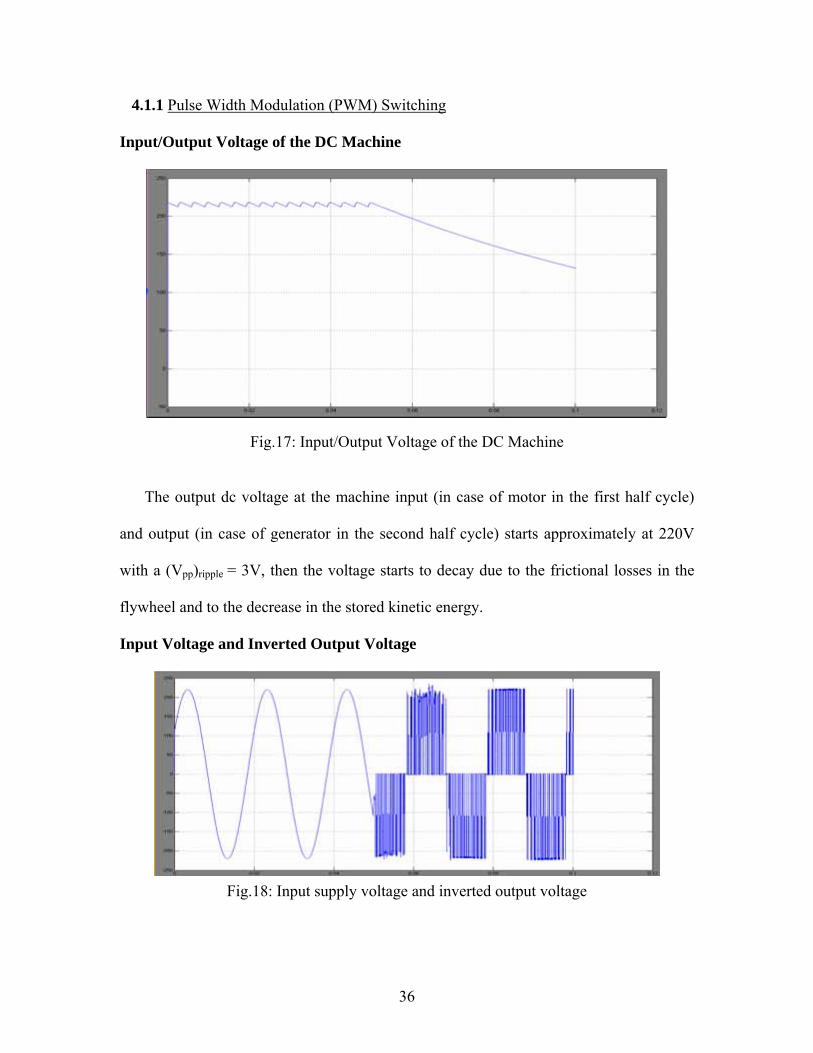
Fig.17: Input/Output Voltage of the DC Machine
The output dc voltage at the machine input (in case of motor in the first half cycle)
and output (in case of generator in the second half cycle) starts approximately at 220V
with a (Vpp)ripple = 3V, then the voltage starts to decay due to the frictional losses in the
flywheel and to the decrease in the stored kinetic energy.
Input Voltage and Inverted Output Voltage
Fig.18: Input supply voltage and inverted output voltage
36

This figure shows the supply voltage in the first half of the simulation (t=0.05) and
the inverter output voltage when the power flow is reversed. In the second phase the dc
voltage supplied from the dc machine will be supplied to the load through an inverter. We
can notice the pulse train of the PWM.
Regulated Boost Converter Output
Fig.19: Regulated Boost Converter Output
The boost converter is needed in the second half of the simulation (when power is
injected from the flywheel to the load). We can notice that the regulated output is 220V
in the steady state. A transient state occurs while switching due to the additive reverse
current.
Filtered Output Voltage
Fig.20: Filtered output voltage (after LC Filter)
37

The output voltage filtered using an LC filter is about 110V (which follows the
formula of three phase PWM inverters where VLL,rms (fund. freq.) =0.612xmaxVd).
There is attenuation in voltage due to the fact that the filter will remove all the additive
harmonics from the PWM signal and only the fundamental signal (sine wave) will be
released. The output voltage will consequently decrease. The LC filter used is not lossy
since the resistive element is only 10Ω. Since the output voltage is 110V, a 110/220V
transformer can be used to change this voltage into 220V which is able to feed the
additional load.
4.1.2 Square Wave Switching
Input/Output Voltage of the DC Machine
Fig.21: Input/Output voltage of the dc machine for square switching inverter
We can notice that the dc machine voltage is about 220V with (Vpp) ripple= 2V. So the
results conform to what we shall get as a dc voltage. The voltage starts to decay due to
the frictional losses of the flywheel which result in a decrease of rotational speed and
38

accordingly a decrease in the flywheel stored kinetic energy. The voltage of the dc
machine will drop consequently.
Input Voltage and Inverted Output Voltage
Fig.22: Input voltage and inverted output voltage for square switching inverter
The above figure shows the output of the inverter. The first 0.05 s shows the output of
the supply whereas the other 0.05 s shows the output of the inverter. We can notice the
output as a square wave. Unstable region exists when the power flow in the circuit is
reversed.
Regulated Boost Converter Output
Fig.23: Regulated boost converter output
39

The converter voltage is regulated to keep the output at 220V. A transient state exists
when switching occurs and additive reverse current causes an increase in voltage.
Filtered Output Voltage (0.05 sec and above)
Fig.24: Filtered Output Voltage
The above figure shows the filtered output using LC filter. The output is
approximately sinusoidal with a peak voltage of 170V (which follows the formula of
three phase square wave inverters where VLL, rms (fund. freq.) =0.78xVd ). The
attenuation in the voltage is justifiable due to the removal of the additive harmonics.
Similarly, we can use a transformer to step up the voltage to 220V in the case where a
220V load is used.
40

5. Implementation and Testing
The different components of the FESS are implemented and tested to verify the
results. The main components that are implemented the inverter and the boost converter.
In our system, a 75W, 220V lamp was used as the additional load that will be fed by the
FESS. Of course, this additional load will not cause a dip on the grid, so testing the
system is done to verify that the kinetic energy stored in the flywheel is converted into
electric energy to supply the load. Accordingly, we first operate the DC machine as a
motor, fed from a 220V DC supply, to rotate and charge the flywheel. The dc motor
operates at a speed of 1500 rpm and thus the flywheel will operate at this speed. After the
flywheel is charged (few seconds), we disconnect the motor from its input terminals and
the machine now operates as a generator with an output voltage starting at 220V and
decaying down to zero due to the decrease in the rotational speed of the flywheel and thus
the stored kinetic energy. The decaying voltage is fed to a boost converter which
maintains a 220V constant DC voltage at its output by varying its duty cycle accordingly
with the decaying input voltage. This boost converter is connected to an single phase
square wave inverter which changes the voltage into a square wave (+220V) - (-220V).
The output of this inverter is fed to an LC LPF which exstracts the fundamental
frequency component from the square wave output of the inverter. The output of the LPF
is a sinusoidal wave of magnitude (4/pi)xVd =280V since Vd=220V. This voltage from
the LPF is sufficient to feed the lamp we are using. Since the rated speed of the machine
is relatively low, the flywheel is not expected to run the generator and thus feed the lamp
for more than 5-7 seconds. The stored kinetic energy in the flywheel is relatively low and
will not be sufficient to run the generator for along period. This is basically the purpose
41

of the FESS which stores kinetic energy and releases it in the form of electric energy to
assist the grid in case of overload for only a short duration. Advanced experiments can
use machines with a speed of tens of thousands of rpm and thus the flywheel can continue
rotating for longer duration.
For our FESS, we will assume that the machine is fed from a 220V constant DC
voltage. Usually this is the case when we have a renewable energy source. The following
is the block diagram of the system we have implemented:
Fig.25: Block diagram of the FESS being operated in hardware
We can see that we need to build three components: the boost converter, the square
wave inverter and the low pass filter. However, we will not build the LC LPF since it
needs an industrial capacitor which is large and expensive. So the output of the inverter
will be fed directly to the load.
42

5.1 DC Machine and Flywheel
The DC machine used is MV 1006-225 DC Machine found in the machines lab at
AUB. It is rated at 220V, 6A, and 1400 rpm. We have connected our DC machine as
separately excited. The machine is fed with a 220V input at its field and at its armature,
and it operates as a motor that rotates the flywheel. This 220V DC is supplied from the
grid to the field excitation terminals with the presence of a field resistor that will limit the
current. The field resistor is high at starting and then it is reduced to increase the speed of
the machine. The field resistor is set with the machine rotating at a speed of 1500 rpm.
When we open the switch, the armature winding will now have a voltage that is being
induced due to the rotation of the flywheel which is releasing its stored kinetic energy
and running the machine as a generator. Running at no-load, the induced voltage of the
generator decays from 220V to 100V in about 12 seconds. However, when we connect a
load, the time measured does not exceed 7 seconds. This time is noticeable and it is
enough to verify the operation of our system. The DC machine used is shown below:
Fig.26: MV 1006-225 DC Machine with coupled flywheel (Machines Lab, AUB)
43

As calculated before, the moment of inertia of the flywheel is .
Accordingly when the motor is running at 1500 rpm, the stored kinetic energy in the
flywheel is given by:
2.0225.0 mKg
J 277.6)6015002(0225.05.0)
602(
21
21 222 ====
xxxnIIE ππω .
In the overload compensation mode, the DC machine will generate an average
voltage of 110V and an average current of 0.35A for the above mentioned load (75W,
220V). Then the average power generated by the dc generator is:
. Accordingly, the estimated time the flywheel will
operate the DC machine as a generator is: time = E / P = (277.6 J) / (38.5 W) = 7.2 sec.
This confirms with the results obtained before when testing the machine with the
flywheel.
WxVIP avav 5.3835.0110 ===
5.2 Inverter
For our project we will use the H-bridge square wave switching inverter. This inverter
will be used to convert the DC voltage to AC voltage in the overload compensation mode
of our FESS. In this mode, the kinetic energy stored in the flywheel will be transformed
into electric energy supplied to the load. The kinetic energy will be used to operate the
DC machine as a generator. The output of the generator will be fed to the inverter that
should produce an AC output voltage to feed the load. Due to friction and the decrease of
stored kinetic energy stored in the flywheel, the output DC voltage supplied by the
generator will decrease from 220V to 0V (when stored kinetic energy is zero).
Accordingly, we need to have a boost DC/DC converter to maintain a 220V at the input
of the inverter.
44

The circuit diagram of the H-bridge inverter is shown in the diagram below:
Fig.27: H-Bridge Inverter/Rectifier
The inverter consists of two legs where each switch on a leg is switched at one time.
So, four power MOSFETs are needed to build the inverter and thus two drive circuits that
control the switching scheme of the four MOSFET switches T1, T2, T3, and T4 of the H-
bridge. T1 and T4 are switched ON simultaneously by the same driver circuit. Similarly
for T2 and T3 such that the two driver circuit generate anti-phase driving signals: when T1
is closed, T2 is open and vice versa. To ensure that there exist a dead time while switching
between T1 and T2 (or T3 and T4), we implemented a time delay circuit using PIC16F84.
The dead-time interval during the transition between the two drivers is necessary to
ensure that the switch is completely turned OFF before the other switch turns ON (on the
same leg) and thus avoid short-circuiting the source voltage.
The components used to build the inverter are:
Four IRFP460 MOSFETS
Two IR2110 Driver circuits
PIC16F84 circuit to generate time delay
Two Opto-couplers 4N27
Resistive load
45

The power MOSFET IRFP460 is characterized by its fast switching capabilities, low
on-resistance and cost-effectiveness. This MOSFET has a rated Drain-to-Source voltage
VDSS = 500V and a rated drain current ID = 20A (from www.alldatasheets.com). This
means that the voltage and current ratings of this MOSFET are well above the maximum
operating voltages and currents which are 220V and 6A respectively. It has an internal
resistance of 0.27Ω which means low power losses and thus efficient switching. A 22Ω
resistor is used to separate the transistor gate and the driver. Also a 100 KΩ resistor is
connected to ensure the gate capacitance discharge during the OFF period.
Since MOSFET IRFP460 needs simple drive requirements, IR2110 driver circuits are
used to provide driving pulses to the gates of the transistors so that VGS > VDS and thus
drive one high side and one low side power MOSFET. This driver circuit provides fast
switching speeds and low power dissipation and can operate in bootstrap principle or
with isolated power supply. The circuit diagram is shown below:
Fig.28: IR2110 driver circuit (from www.alldatasheets.com )
46

A switching control signal is applied to HIN and LIN pins which are the logic inputs for
respectively the high and low side gate driver outputs. HIN and LIN are respectively in the
range of 0-15V. VSS, SD, and COM are connected to ground whereas VDD and VCC are
connected to 15V supply. A 20V isolated power supply is connected across the pins
labeled VB and Vs to account for the voltage offset and thus ensure VGS>VDS. A fast
recovery diode FR157 with peak inverse voltage of 1000V is used to have a peak inverse
voltage more than that applied to the MOSFET, and it provides a path for free-wheeling
currents that passes during operation.
The signals to the gates of transistors T1and T2 (or T3 and T4) must be anti-phase to
avoid short-circuiting the supply. For our driver circuit, the pin HO, which is the high
side gate drive output, is connected to the gate of the high transistor on one leg, and LO,
which is the low side gate drive output, is connected to the low transistor of the other leg
(diagonally opposite). LO has a range from 0V to 15V, whereas HO varies from 0 to
(220+15) = 235V.
We have to ensure a dead-time while switching between the two transistors on the
same leg. This is done using a PIC16F84 time delay circuit that provides two anti-phase
output signals with a dead-time of 0.5ms. Each signal will be ON for 9.5ms so that we
ensure that the signal frequency remains 50Hz. The PIC is programmed using MPLAB
software, and the code is shown in Appendix A.
47

The circuit diagram showing PIC connections is as follows:
Fig.29: PIC16F84 circuit Diagram
Since the output voltage of the PIC is a square wave with amplitude of 5V, we
connect an opto-coupler circuit so that the output will be a square wave with amplitude
15V. Also the opto-coupler will used to protect the driver circuits and the PIC circuit
from any fault that may damage it. The 0-5V square wave is fed to the inputs of the
driver circuit (HIN and LIN). The opto-coupler used is the 4N27 chip and its circuit
connection is shown as follows:
Fig.30: Opto-coupler 4N27 schematic and circuit diagram
48

When a square wave signal is applied across the infra-red LED, the base of the
transistor is activated and the transistor will act as an “ON” switch, otherwise it will be
“OFF”. Accordingly, the resulting output voltage at the emitter of the transistor will be a
square wave signal of amplitude VCC (in our case VCC =15V and input at pin 1 is a 5V
square wave). To connect the opto-coupler circuit, we connect a 100 Ω resistor at the
collector and another one at the cathode of the LED to limit the current flowing in it. The
maximum current allowed to pass through the LED is 60 mA, and since the maximum
voltage applied by the PIC is about 5V, then the resistance is:
Rc= 5V/0.06A = 83.33 Ω, so we use a 100Ω resistor.
A 2 KΩ resistor connects the emitter of the transistor to the ground to obtain a quick
discharge; otherwise, we obtain a slow capacitive discharge from the transistor during the
“OFF” cycle. This discharge gives a bad square wave with an unwanted DC offset
looking like:
Fig.31: Slow capacitive discharge of opto-coupler
49

The block diagram of the H-bridge inverter is shown below:
Fig.32: H-bridge inverter signal propagation
Then the schematic diagram of the inverter is drawn using ORCAD. We first draw
the components with their connections. Then we create a netlist of the file and use the
Layout Plus from ORCAD package to open the netlist file and create a .max file. This file
will contain the footprints of the inverter components. Components such as inductor,
isolated power supply, and junctions do not have their footprints included in the software,
so we have to design their footprints by taking measurements. Then we autoroute the
connections and every component is placed in its place.
50
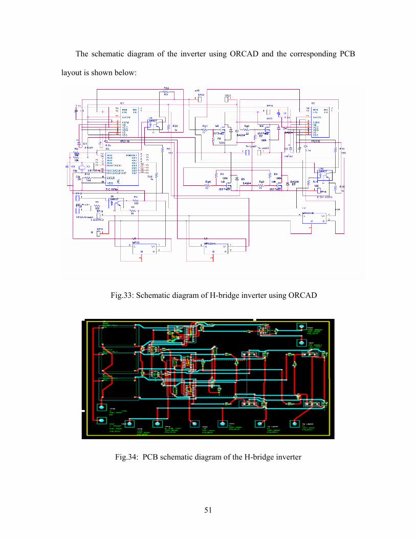
The schematic diagram of the inverter using ORCAD and the corresponding PCB
layout is shown below:
Fig.33: Schematic diagram of H-bridge inverter using ORCAD
Fig.34: PCB schematic diagram of the H-bridge inverter
51

In the above figure, we can notice two layers: red and blue. This is due to the large
number of connections which will lead to an upper and lower layer. This diagram with
the addition of the acidic solution (FeCl3) is printed on a PCB board. Then the
components are placed in their place and the circuit is as follows:
Fig.35: H-bridge Inverter PCB
Testing the circuit with 220V DC input, we get the following output:
Fig.36: H-bridge inverter output (220V)
52

Accordingly, the results are verified and we obtain from 220V DC voltage a square
wave signal of peak voltage 220V. We can see the delay time while switching which
done to avoid short-circuiting the supply voltage. The output frequency is 50Hz as
required.
5.3 Boost Converter
The role of the Boost converter is to maintain a constant 220V DC output
voltage while having a decaying input voltage at its input. This operation requires
a change in the duty cycle of the switch in the boost circuit in compliance with the
change in input voltage according to the following formula: Vout /Vin =1/(1-D).
This change in duty cycle is achieved by using a PIC controller to control the
switching of the MOSFET in the boost.
For the boost converter circuit, we have used one opto-coupler 4N27, one
driver circuit using IR2110 chip, one MOSFET IRFP460, an inductor of 240µH, a
capacitor of 47µF and a fast recovery diode FR607.
The values of the inductance and capacitance were calculated before to be
180.8µH and 36.3µF respectively. Since these values are not available in the
market, we go to the next higher values, and we find C = 47µF at Vr=400V. For
the inductor, it was wound manually using ferrite core and copper torroids, and
we used the following formula to determine the number of turns needed:
L = µoµrN2.A /(2.π.r)
Where: µo = 4 π x 10-7,
µr is the relative permeability of the core,
53

N is the needed number of turns,
A is the cross sectional area of the core,
r is the mean radius of the core
Since the core is of a rectangular cross-section, measurements have shown:
r = 1.1 cm
A = 0.77 cm2
To find µr, we wound a test inductance and measured its inductance using the L-C meter
and counted its number of turns then calculated µr. The resulting µr was 8000.
Thus, for L = 240 µH, we get N = 5 turns.
The operation of the driver circuit for the MOSFET operation of the circuit is
the same as that in the case of the inverter. First of all, we get a square wave
signal 0-5Vof varying duty cycle from the PIC control. The duty cycle varies
depending on the change of the input voltage of the boost. This square wave is
sent to pin 1 of the opto-coupler. The output at pin 4 is a square wave 0-15V
having the same phase as the input signal (with varying duty cycle) from the PIC.
Then the output signal from the opto-coupler is sent to Lin of the IR2110
chip. We connect VCC and VDD to 15V, whereas SD, COM and VSS are grounded.
So now, we get a square wave 0-15V at LO which drives the MOSFET switch of
the boost circuit. By driving the MOSFET, we mean that the LO pin from the
driver connects to the gate of the MOSFET through a 47Ω resistor of 15W rating.
In addition, the ground which is connected to the source of the MOSFET is a
54

common ground to all the circuit. Thus, this same ground is connected to SD,
COM, VSS and to the negative pole of the supply.
5.3.1 Boost Control Using PIC
The boost should maintain a 220V output voltage while its input voltage decays from
220V down to zero due to friction and kinetic energy losses. The relation between the
output and input voltages of the boost is given by the following:D
VV in
out −=
1, where D is
the duty cycle. Accordingly with Vin decreasing with time, the duty cycle should increase
in order to compensate for this decrease and keep Vout at a constant voltage of 220V.
A Pulse-Width-Modulated (PWM) signal with varying duty cycle should be
generated to control the switching of the transistor. This signal will supply the driver
circuit of the MOSFET and thus control its ON and OFF switching. PIC16F877 is used to
generate PWM signals with variable duty cycles. It has the advantage of A/D conversion
and generating PWM signals for a determined duty cycle. So to program this
microcontroller, we have to configure the Analog-to-digital conversion module and the
PWM module (from PIC16F877 datasheet).
Configuring A/D Module:
Discretize analog voltages (between 0 - 5V)
Develop relationship between analog and digital values (8 bit A/D)
o digital value 255 = 5V analog
o digital value 0 = 0V analog
Assign voltage range to specific analog
Check read digital value against predicted range
Determine if new value has been sent
55

To achieve this function we do the following:
Initialize A/D registers (ADCON0, ADCON1)
A/D must wait a fixed amount of time before starting next conversion
Perform Loop:
o Set ADCON0 bit to start conversion
o Poll ADCON0 bit to see if conversion finished
o Poll INTCON bit to see if Timer0 overflow occurred
o Clear Timer0 interrupt
o Perform conversion
o Check if values matches previous
o Send to CRT if new value
Configuring PWM Module:
Set the PWM register by writing to the PR2 register
Set PWM duty cycle in CCPR1L and CCP1CON < 5 : 4 >
Make the CCP1 pin an output by clearing TRISC<2> bit
Set TMR2 prescale value.
Enable Timer2 by writing to T2CON
Configure the CCP1 module for PWM operation
The code used to program PIC16F877 is shown in Appendix B.
Now we have a PIC circuit that can take an analog voltage between 0V and 5V and
accordingly generate a PWM signal with a duty cycle matched to the input analog voltage
as shown in the matching scheme in the code. As mentioned before, the duty cycle of the
PWM signal generated should increase as the voltage supplied by the generator drops, so
we have to start with a negligible duty cycle (approximately zero) and then increase this
duty cycle until we reach 99% (Vout = 10xVin). In reality, we are interested in the region
until the generator voltage is above 100V since below this value the energy stored is
56

negligible, and it is meaningless to run this system. Accordingly a relay is used to turn
OFF the boost (and consequently the inverter) in case the generator voltage goes below
100V. Since the input analog voltage range of the PIC16F877 is from 0-5V, then we have
to do a mapping between the generator voltages from 100-250V to 0-5V. This feedback
from the generator will be used to control the duty cycle and generate the corresponding
PWM signal that will maintain boost output voltage of 220V. This feedback is done using
a differential probe that has output voltages in the range of 0-5V. The differential probe is
available in the lab and will be used for this purpose. A DC capacitor is connected to the
boost output in order to stabilize the output voltage at a value of 220.
A block diagram of the boost converter feedback control is shown below:
Fig.37: Boost converter with control block diagram
The schematic of the circuit was drawn using ORCAD as with the case of the
inverter. The circuit diagram is shown:
57

Fig.38: Boost converter schematic diagram using ORCAD
Then this circuit is used to draw the PCB diagram:
Fig.39: Boost converter PCB diagram
58

Unlike the inverter PCB diagram, the PCB diagram of the boost converter is
one layer only. Afterwards, the circuit was built on a PCB. The following figure
shows the boost converter built on a PCB:
Fig.40: Boost converter PCB
Testing the boost capacitor is done in the overload compensation mode after
the flywheel acquires its maximum speed, and the machine is disconnected to
operate as a generator. The circuit was tested on the machine while having a 75W,
220V lamp as a load. The output ranges from 220V – 240V and this output lasts
for about 7sec. Thus the testing of the boost verifies the expected results. A
4700µF, 250V DC capacitor was connected at the output of the boost in parallel
with the load in order to smooth the output voltage and reduce the ripples. Thus,
the operation of the boost was verified and conformed to our expectations.
59

6. Budget Component
Component Parts Number Price of one part ($)
Total price of part ($)
Boost PIC 16F877 1 6 6 Opto-couplers 2N27 1 0.7 0.7 Resistors for opto-couplers 3 0.1 0.3 Driver IR2110 1 2.5 2.5 MOSFET IRFP460 1 2 2 Gate resistor 47ohm 20W 1 0.75 0.75 Wound inductor 240µH 1 Available Available Diode FR607 1 0.25 0.25 Capacitor 47microF, 450V 1 1 1 IC holder for driver-14pin 1 0.1 0.1 IC holder for opto.-8pin 1 0.08 0.08 XT oscillator 4MHz 2 0.5 1 Capacitors 33pF 4 0.1 0.4 Junctions 14 2.5 2.5 Inverter PIC16F84 1 2.5 2.5 Optocoupler 2N27 2 0.6 1.2 Resistors for optocouplers 6 0.1 0.6 Drivers IR2110 2 2.5 5 MOSFETs IRFP460 4 2 8 Gate resistors for mosfets
22Ω, 15W 4 0.75 3
Diodes FR607 4 0.25 1 IC holder for PIC16F84 – 18
pin 1 0.1 0.1
IC holders for drivers-14pin 2 0.1 0.2 IC holders for optocoupler-
8pin 2 0.08 0.16
Diodes FR157 2 0.25 0.5 PCB Double layered PCB (30cm x
45cm) 1 22 22
Lamp Load lamp (75W 220V) 1 Available Available LPF Wound inductor 2.25mH 1 Available Available Capacitor 4700uF, 250V DC 1 13.5 13.5 Resistor 0.33Ω 1 0.6 0.6 Total = $ 75.94
The total net cost indicated above is that of the power electronics part. This cost of
course does not include the development and testing cost which is higher than this value.
60

The cost of developing and testing was about $220 which is 3 times that of the net cost of
the final product. Also, this excludes the cost of the DC machine (most expensive) and
that of the flywheel (cost depends on the design). This system can be used as a backbone
for other storage systems and it can be sold as a package. Accordingly, we can see that
the cost of the FESS excluding that of the machine is economically challenging and
promising.
61

7. System Evaluation
No doubt that energy storage systems are very important for delivering high quality
energy to customers. However, when we need to discuss the environmental, economical,
health and safety, manufacturability, and sustainability aspects of the specific flywheel
energy storage system, we need to compare it to other alternatives like the chemical
batteries.
When studying the economical aspect of a flywheel energy storage system, we
should first of all determine the purpose of the system. This means that we have to
determine whether the system should be used for supplying energy for a few minutes, or
for one or two hours. This is because we have found out that an FESS with relatively
small discharge time less than 20 minutes is more economical than many alternatives
supplying energy for this time. This is because the main cost in designing the FESS is the
cost of the machine and the cost of the other system components is relatively low
(around $100). A flywheel can be very economical if its application is mainly to supply
energy for a short duration of time. In this case, the machine’s cost is not very high and
the flywheel can be very efficient in supplying energy. The following figure shows a
comparison between several energy storage systems’ capital costs versus the discharge
time, first for less than 20 seconds, and the second for few minutes.
62

Fig.41: Comparison of Capital Costs of different storage systems [1]
As we can see from the above figure, low speed flywheel energy storage systems are
the most economical at low discharge time. It is even more economical when the
discharge time is less than 20 or 30 minutes, however its cost continues on rising until
other alternatives become more economical at high discharge times. Thus, the design we
are having which is required to supply energy for a few seconds is more economical than
all other alternatives. In addition, in our FESS design, we have used a machine found in
our labs; thus, we have saved a lot of money by not buying a new machine and using it in
our design. Thus, the design we are doing is very economical since it only involves the
cost of power electronic components which are cheap.
The FESS is an environment friendly system being made of largely inert and benign
materials unlike chemical batteries which can release chemicals damaging to the
environment. Flywheels are not affected by temperature changes, as are chemical
63

batteries. The FESS is composed of a machine connected to a flywheel with some power
electronic components like the boost and inverter. Neither the electronic components nor
the machine are harmful to the environment, thus there is no need to be concerned
regarding this aspect.
As for the safety and health aspect, the FESS can cause some safety problems. The
use of flywheel accumulators is currently hampered by the danger of explosive shattering
of the massive wheel due to overload. One of the primary limits to flywheel design is the
tensile strength of the material used for the rotor. Generally speaking, the stronger the
disc, the faster it may be spun, and the more energy the system can store. When the
tensile strength of a flywheel is exceeded the flywheel will shatter, releasing all of its
stored energy at once; this is commonly referred to as "flywheel explosion" since wheel
fragments can reach kinetic energy comparable to that of a bullet. Consequently,
traditional flywheel systems require strong containment vessels as a safety precaution.
When talking about these safety hazards, we are talking about systems in which the
motor rotation can reach speeds of more than 40,000 rpm. However, for our machine
which runs at 1400rpm, there is no risk of shattering at all because the speed is relatively
slow and would not result in shattering of the flywheel. Thus, in our system, safety and
health problems resulting from flywheel explosion are not serious.
As for the manufacturability aspect of our system, the FESS is not complicated to
manufacture, although the complexity can vary extensively based on the purpose of use
of the FESS. For example, FESS systems with very high speeds need to be more
complex than those with low speeds and part of this complexity is needed for safety
precautions. But, in general, an FESS like ours is not hard to manufacture although one
64

can face some problems in the power electronics components needed. In our system, we
have tried to minimize the complexity of our design by using a DC machine requiring
only one inverter/rectifier bridge. In case we have used an AC machine, we would have
needed two inverter/rectifier circuits so that we can supply an AC voltage with frequency
similar to that of the grid.
When talking about the sustainability, we have to mention that, compared to a
chemical battery, a flywheel energy storage system has a much higher life. It can live for
more than 20 years provided that it is given some regular maintenance. On the other
hand, the life of a battery doesn’t exceed 7 years in the best case. The state of charge of
an FESS is provided by direct readout of rotational speed and can provide high power
output at high voltage, and is significantly lighter and smaller than a battery system
which can provide comparable power output.
7.1 Project Outcomes
No doubt that this FYP has added much to our engineering knowledge. The project is
a combination of many fields in electrical and mechanical engineering. It includes power
electronics, electric machines and drives, control, and mechanical design, so it benefited
us and widened our scope in these fields. The main components which we have
implemented in this project were power electronic components. In addition, choosing the
machine to operate our system has improved our knowledge in machines and drives. We
have also controlled the boost converter using PIC microcontroller.
Aside from the engineering benefit, the project has increased our teamwork skills.
This is a natural consequence as a result of working the whole year with a group of three
65

students. Thus, we have learned how to collaborate with our colleagues, and how to
interact with our supervisor regarding some design and implementation problems.
Finally, we can say that the project we built was successful in the way that we have
managed to simulate the whole system and verify its operation. Also, we have succeeded
in implementing the main part of the circuit which is the backbone for any flywheel
energy storage system.
7.2 Future Work
FESS can be implemented for several usages in the future. The power electronics
parts, i.e. the inverter and the boost converter, with their controls, can be the back bone of
other energy storage systems such as batteries or super capacitors since such energy
storage devices use the process of bi-directional power flow. They could also be used
with different renewable energy sources producing DC voltages such as a wind farm with
rectified output, a solar array, or a photovoltaic array.
As for future work in power electronics, a 3-phase inverter could be implemented to
supply 3-phase loads or to be synchronized with the grid.
Concerning the machine, high speed and high power machines are preferable for such
systems (FESS) so that they can supply power to a larger load for a longer period of time.
Such machines are not available at AUB and they could be part of a future research. The
improvement in the electric machine is the important for any advancement in the system.
The rotational speed of the machine affects mostly the stored kinetic energy in the
flywheel and thus the time the FESS can supply the load.
66

Moreover, the flywheel mounted on the machine could be of larger size to increase its
moment of inertia and thus store larger kinetic energy. The material of the flywheel could
also be improved such as using carbon composites (carbon fibers and resins) [3] or other
fiber materials. This would enhance the operation of the system by decreasing the size of
the flywheel while maintaining high mass.
The system could also be improved and tested for being used from an AC source
instead of the DC source coming from the controlled renewable energy supply. The AC
source is much more widely spread so that the system could be implemented for any
energy storage purpose anywhere.
The control of the system could be changed by using the LabVIEW FPGA Module so
that it has a friendly user interface even though such control is more expensive than using
commercial microcontrollers. Using such a system provides automatic switching
schemes.
Last but not least, an industrial capacitor of ratings 4700µF, 220V AC would solve
the problem of implementing the low pass filter.
67

8. Conclusion
In this project, we have discussed the flywheel energy storage system (FESS). The
system basically includes a two way energy flow scheme so that energy is injected into
the flywheel in the form of kinetic energy, and drawn from the machine driving the
flywheel in the form of electric energy. After showing the block diagram for our system
and providing some general system description, we have presented alternatives for all the
components that are needed to build the FESS. Advantages and disadvantages of these
alternatives have been discussed, and then the components required were chosen
depending on their availability, performance, cost and reliability.
Then we modeled our design using SIMULINK, and simulated it in order to verify
the results. We have modeled our flywheel as a capacitor and added a resistor in parallel
to model the voltage drop in the generator DC voltage. The obtained results were very
close to the anticipated ones, and our design model is thus verified.
After simulating the whole model using SIMULINK, we have decided to build up and
test the system. The flywheel can be charged by using a renewable energy source or a DC
source from grid. After being charged, it can discharge its energy inducing a DC voltage
out of the machine. This DC decaying voltage is supplied to the boost converter which
maintains a constant 220V DC voltage at the input of the inverter. The output of the
inverter supplies the load. Control schemes were done using PIC microcontrollers. The
test of the system was done as anticipated for a short period of time (7 sec).
We have considered various aspects that affect the FESS including economical,
environmental, safety and health considerations and compared them to other alternatives.
68

9. Acknowledgements
We would like to thank our Supervisor Professor Sami Karaki and Mr. Khaled
Joujou for their assistance and guidance. We would like also to thank our professors
in the ECE department who helped us finish our project. In addition, we thank our
fellow colleagues Ahmad Chabacklo and Hussein Hajo for their support.
69

10. References
1. Boyes, J.; Clark, N.; Flywheel Energy Storage and Super Conducting Magnetic
Energy Storage Systems; Sandia National Laboratories; Seattle, Washington; July
19,2000; retrieved via http://www.electricitystorage.org/
2. Chapmann, S.; Electric Machinery Fundamentals; McGraw Hill International
Edition; Fourth Edition; 2005
3. Dettmer, R.; Spinning Reserve; Intemational Energy Systems; South Wirral, UK;
January 1997
4. Jeoung, H.; Choi, J.; High Efficiency Energy Conversion and Drives of Flywheel
Energy Storage System using High Temperature Superconductive Magnetic
Bearings; School of Electrical and Electronics Engineering Chungbuk National
University; S Korea;
5. Kenny, B.; Kascak, P.; Hofmann, H.; Mackin, M.; Santiago, W; Jansen, R.;
Advanced Motor Control Test Facility for NASA GRC Flywheel Energy Storage
System; Technology Development Unit NASA; July 2001
6. Mohan, N.; Undeland, T.; Robbins, W.; Power Electronics: Converters,
Applications, and Design; John Wiley & Sons, Inc.; 2003
7. Samineni, S.; Johnson, B.; Hess, H.; Law, J.; Modeling and Analysis of A
Flywheel Energy Storage System for Voltage Sag Correction
8. Sedra, A.; Smith, K.; Microelectronic Circuits, Fifth edition; Oxford University
Press; USA; 2004
9. SilvaNeto, J.; Rolim, G.; Control of a Power Circuit Interface of a Flywheel-based
Energy Storage System; UFRJ, Cidade Universitiria, Rio de Janeiro, Brazil,
70

10. W. H. Kim, J. S. Kim, J. W. Baek, H. J. Ryoo, G. H. Rim, Improving Efficiency
of Flywheel Energy Storage System with A New System Configuration; Sung-Ju
Dong, Chang-Won, Kyung-Nam, Korea ;Korea Electrotechnology Research
Institute; Korea Institute of Machinery & Metals.
11. Weissbach, R.; Karady, G.; Farmer, R.; A Combined Uninterruptible Power
Supply and Dynamic Voltage Compensator Using a Flywheel Energy Storage
System; IEEE Transactions on Power Delivery, Vol. 16, No. 2; April 2001
Secondary References:
12. Alan, I.; Lipo, J.; “Induction Machine Based Flywheel Energy Storage System”;
IEEE Transactions on Aerospace and Electronic Systems; Vol. 39, No. 1; January
2003
13. Bomemann, H.; Sander, M.; “Conceptual System Design of a 5 MWh/100 MW
Superconducting Flywheel Energy Storage Plant for Power Utility Applications”;
IEEE Transactions on applied superconductivity; vol. 7, NO. 2, June 1997
14. Boyes, J.; Clark, N.; “Technology for energy storage flywheels and super
conducting magnetic energy storage”; Proceedings of the IEEE Power
Engineering Society Transmission and Distribution conference; V. 3, 2000
15. Fang, J.; Lin, L.; Yan, L.; Xiao, L.; “A New Flywheel Energy Storage System
Using Hybrid Superconducting Magnetic Bearings”; IEEE Transactions on
applied superconductivity; Vol. 1 I, No. I, March 2001
71

16. Leclercq, L.; Robyns,B.; Grave, J.; “Control based on fuzzy logic of a flywheel
energy storage system associated with wind and diesel generators”; Elsevier
Database; retrieved via www.elsevier.com ; 2003
17. Swett, D.; Blanche, J.; “Flywheel Charging Module for Energy Storage Used in
Electromagnetic Aircraft Launch System”; IEEE Transactions on Magnetics; Vol.
41, No. 1; January 2005
72

Appendix A
Time Delay PIC Code: title "Controller" list p=16f84 radix hex include "p16f84.inc" COUNT1 EQU d'12' ; Initializes COUNT1 to 12 NUM1 EQU d'13' ; Initializes NUM1 to 13 CHECK EQU d'14' ; Initializes CHECK to 14 NUM2 EQU d'16' ; COUNT2 EQU d'15' ; Initializes COUNT2 to 15 NUM3 EQU d'17' ORG 0x0 MOVLW b'11000110' MOVWF NUM1 MOVLW b'00000110' MOVWF NUM2 MOVLW b'00111101' MOVWF NUM3 BSF STATUS,RP0 CLRF TRISA BCF STATUS,RP0 START CLRF COUNT1 CLRF COUNT2 CLRF CHECK BTFSC PORTB,3; RB3 IS THE ENABLE SIGNAL GOTO SETTING GOTO START SETTING BSF PORTA,0 BCF PORTA,1 GOTO D9.5 D9.5 INCF COUNT1 MOVF COUNT1,0 SUBWF NUM1, 0 BTFSC STATUS,2 GOTO C6 NOP GOTO D9.5 C6 CLRF COUNT1 INCF COUNT2 MOVF COUNT2,0 SUBWF NUM2,0
73

BTFSC STATUS,2 GOTO SETTING2 GOTO D9.5 SETTING2 CLRF COUNT1 BCF PORTA,0 GOTO D0.5 D0.5 INCF COUNT1 MOVF COUNT1,0 SUBWF NUM3, 0 BTFSC STATUS,2 GOTO CLEAR GOTO D0.5 CLEAR CLRF COUNT1 CLRF COUNT2 BSF PORTA,1 GOTO D9.5N D9.5N INCF COUNT1 MOVF COUNT1,0 SUBWF NUM1, 0 BTFSC STATUS,2 GOTO C6N NOP GOTO D9.5N C6N CLRF COUNT1 INCF COUNT2 MOVF COUNT2,0 SUBWF NUM2,0 BTFSC STATUS,2 GOTO SETTING3 GOTO D9.5N SETTING3 BCF PORTA,1 GOTO D0.5N D0.5N INCF COUNT1 MOVF COUNT1,0 SUBWF NUM3, 0 BTFSC STATUS,2 GOTO START GOTO D0.5N END
74

Appendix B
PWM Code
; Begin ORG 0x0000 BCF PCLATH,3 BCF PCLATH,4 GOTO L0002 ORG 0x0004 RETFIE L0002: ; Define ADC_CLOCK = 3 'default value is 3 ; Define ADC_SAMPLEUS = 10 'default value is 20 ; TRISA = 1 BSF STATUS,RP0 MOVLW 0x01 MOVWF 0x05 BCF STATUS,RP0 ; TRISC = 0 ; ADCON1 = 0 BSF STATUS,RP0 CLRF 0x1F BCF STATUS,RP0 ; Dim duty As Byte ; The address of 'duty' is 0x2C duty EQU 0x2C ; Dim an0 As Word ; The address of 'an0' is 0x2D an0 EQU 0x2D L0001: ; Adcin 0, an0 BSF STATUS,RP0 BSF ADCON1,ADFM BCF ADCON1,ADCS2 MOVLW 0x00 BCF STATUS,RP0 MOVWF R0L CALL A001 BSF STATUS,RP0 MOVF ADRESL,W BCF STATUS,RP0 MOVWF 0x2D MOVF ADRESH,W MOVWF 0x2E ; duty = an0 MOVF 0x2D,W MOVWF 0x2C ; duty = 255
75

; PWMon 1, 9 MOVLW 0x3F BSF STATUS,RP0 MOVWF PR2 BCF TRISC,2 BCF STATUS,RP0 CLRF CCPR1L BCF CCP1CON,CCP1X BCF CCP1CON,CCP1Y BCF T2CON,T2CKPS0 BCF T2CON,T2CKPS1 BSF T2CON,TMR2ON MOVLW 0x0C IORWF CCP1CON,F ; PWMduty 1, duty MOVF 0x2C,W MOVWF R0L BTFSC R0L,0 BSF CCP1CON,CCP1Y BTFSS R0L,0 BCF CCP1CON,CCP1Y BTFSC R0L,1 BSF CCP1CON,CCP1X BTFSS R0L,1 BCF CCP1CON,CCP1X BCF STATUS,C RRF R0L,F BCF STATUS,C RRF R0L,W MOVWF CCPR1L ; Goto loop GOTO L0001 ; End of program L0003: GOTO L0003 ; Division Routine D001: MOVLW 0x10 MOVWF R3L CLRF R2H CLRF R2L D002: RLF R0H,W RLF R2L,F RLF R2H,F MOVF R1L,W SUBWF R2L,F MOVF R1H,W BTFSS STATUS,C INCFSZ R1H,W SUBWF R2H,F BTFSC STATUS,C GOTO D003 MOVF R1L,W ADDWF R2L,F MOVF R1H,W BTFSC STATUS,C
76

INCFSZ R1H,W ADDWF R2H,F BCF STATUS,C D003: RLF R0L,F RLF R0H,F DECFSZ R3L,F GOTO D002 MOVF R0L,W RETURN ; Waitms Routine W001: MOVF R0L,F BTFSC STATUS,Z GOTO W002 CALL W003 DECF R0L,F NOP NOP NOP NOP NOP GOTO W001 W002: MOVF R0H,F BTFSC STATUS,Z RETURN CALL W003 DECF R0H,F DECF R0L,F GOTO W001 W003: MOVLW 0x0C MOVWF R2H W004: DECFSZ R2H,F GOTO W004 NOP NOP MOVLW 0x12 MOVWF R1L W005: DECFSZ R1L,F GOTO W006 CALL W007 CALL W007 NOP NOP RETURN W006: CALL W007 GOTO W005 W007: MOVLW 0x0D MOVWF R2L W008: DECFSZ R2L,F GOTO W008 NOP RETURN ; Adcin Routine A001: RLF R0L,F RLF R0L,F
77

RLF R0L,F MOVLW 0x38 ANDWF R0L,F MOVLW 0xC1 IORWF R0L,W MOVWF ADCON0 MOVLW 0x0A MOVWF R4L CALL X001 BSF ADCON0,GO A002: BTFSC ADCON0,GO GOTO A002 BCF PIR1,ADIF BCF ADCON0,ADON RETURN END
78